Article

Structural Responses of a Supertall Building Subjected to a Severe Typhoon at Landfall

1
Joint Research Center for Engineering Structure Disaster Prevention and Control, Guangzhou University, Guangzhou 510006, China
2
School of Civil, Environmental & Mining Engineering, The University of Adelaide, Adelaide 5005, Australia
*
Author to whom correspondence should be addressed.
Appl. Sci. 2020, 10(8), 2965; https://doi.org/10.3390/app10082965
Submission received: 25 March 2020 / Revised: 9 April 2020 / Accepted: 21 April 2020 / Published: 24 April 2020
(This article belongs to the Special Issue Vibration-Based Structural Health Monitoring)

Abstract

:
Typhoon Mangkhut (1822) was one of the strongest tropical cyclones that ever impacted the south coast of China in past decades. During the passage of this typhoon, the structural health monitoring (SHM) system installed on a 303 m high building in this region worked effectively, and high-quality field measurements at nine height levels of the building were collected successfully, which provides a valuable opportunity to explore the dynamic properties of the building and the associated wind effects. In this study, the typhoon wind characteristics are presented first based on in-situ measurements at two sites. Acceleration responses of the building is then investigated, and the building’s serviceability is assessed against several comfort criteria. This study further focuses on the identification of modal parameters (i.e., natural frequency, damping ratio, and modal shape) via two methods: stochastic subspace identification (SSI) method and a method based on combined use of spectral analysis and random decrement technique (RDT). The good agreement between the two results demonstrates the effectiveness and the accuracy of the adopted methods. The obtained results are further compared with the stipulations in several technical codes as well as simulation results via finite element method to examine their performances in this real case. The amplitude dependence of natural frequencies and damping ratios of the studied building are also stressed.

1. Introduction

There is a fast development of high-rise buildings at coastal areas where tropical cyclones (TCs) may attack frequently [1]. As these buildings are commonly characterized by low natural frequencies and high flexibilities, they become considerably sensitive to wind load [2]. In light of the significance of wind effects on the safety and the serviceability of such skyscrapers, continuous efforts have been made on this topic via different methods, such as wind tunnel tests and numerical simulation [3,4,5,6,7]. However, due to the complexity of involved issues, field study is generally regarded as the most credible way for such investigations at present.
During the last decades, numerous filed studies on dynamic performance of high-rise buildings under wind action have been conducted [8,9,10,11,12,13,14]. Among these works, Kijewski-Correa, et al. established structural health monitoring (SHM) systems on four skyscrapers in Chicago and Dubai and analyzed the structure dynamic properties and the associated wind effect based on collected records [15,16,17]. Wu et al. measured the wind-induced vibration response of a 79-story tower during the passage of several typhoons [18]. Fu et al. analyzed wind characteristics and wind effects on super-tall buildings based on field records from the SHMs of three towers [19,20]. Au et al. employed the fast Bayesian frequency domain method to observe the modal characteristics of two high-rise buildings under the action of typhoon [21]. He et al. analyzed the dynamic properties of a 492 m high building, and the functional performance of affiliated active-tuned-mass-damper (ATMD) system was examined [22,23]. Li and his team explored the wind-induced responses of several super-tall buildings at coastal areas. Results from field measurements were further used to verify the validity of wind tunnel testing techniques [24,25,26,27]. Wang et al. and Wu et al., among others, also analyzed the dynamic characteristics and the wind-induced response of high-rise buildings [28,29].
Undoubtedly, the aforementioned studies provide useful insights for further understanding the characteristics of structural dynamics of high-rise buildings. However, a majority of these investigations were based on field records collected at a single height level, while those based on multi-levels of records have been comparatively less reported. The reason mainly lies in that field measurement at multiple height levels of a high-rise building is much more challenging and costly than the one at a single level. Typically, not only considerably more devices are required, but also the output signals from varied devices should be synchronized and collected with a uniform format. However, studies based on multi-levels of records are of great practical interests, since they have overwhelming advantages against those based on a single level of records. First, they can provide more information of the building structure (e.g., mode shape), and such information is significantly useful for many relevant studies and practices such as updating finite-element (FE) models and correcting wind tunnel test results. Second, results based on multi-levels of records are usually regarded as more accurate and credible than those associated with a single level of records, as more measurement information and more robust methods/algorithm are utilized [30].
During 15–18 September 2018, Typhoon Mangkhut got close to and made landfall on the south coast of China at a severe-typhoon intensity level and exerted severe impact on Guangzhou. During this period, the SHM system installed on a 303 m high-rise building at Guangzhou worked smoothly, and field records at nine height levels of the building were collected successfully. This study focuses on the structural responses of this skyscraper with a primary objective of further understanding the dynamic properties of and the typhoon effects on this building based on multi-levels of field measurements. The serviceability of the studied super-tall building subjected to this severe typhoon is assessed, and the working performances of two different modal identification methods are examined. The remainder of this article is organized as follows. Section 2 introduces the SHM system of the study building and the datasets. Section 3 presents the main methods and techniques for data analysis. In Section 4, typical results about modal parameter identification, structural response, and comfort evaluation from the field measurements are presented and discussed. Main results and conclusions are summarized in Section 5.

2. SHM System and Dataset

2.1. Study Site and SHM System

Leatop Plaza is located at the entrance of the Pearl River in the New City Central Business District (CBD) area of Guangzhou, Guangdong Province of China. It is of 303 m in height and contains 65 floors above ground. Except for the topmost floor, which has a wedge-shaped configuration, all the other floors are cuboid in shape and have a square cross-section with the side length equal to 45.7 m. This building adopts a structural system that consists of a steel diagonal steel frame and a reinforced concrete core tube. An aerial view of the building is shown in Figure 1.
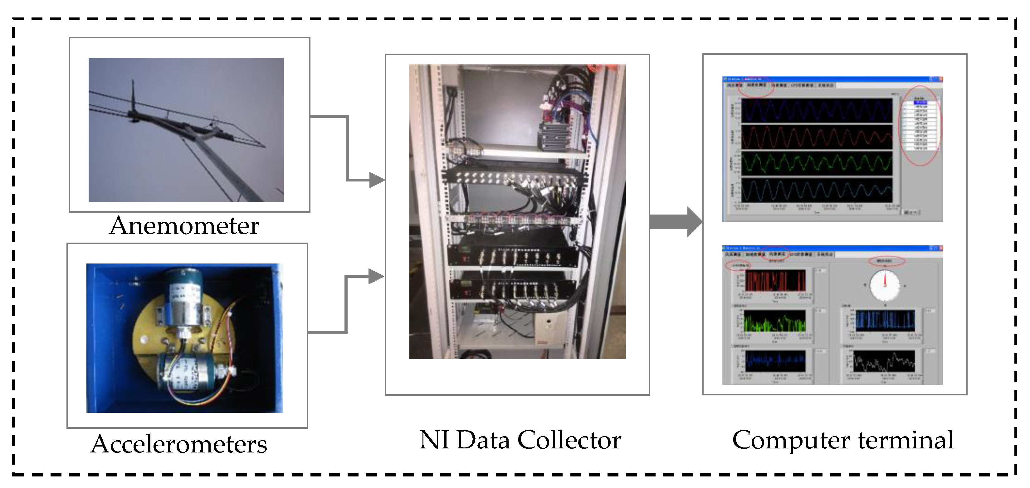
An SHM system was established on the building to provide in-situ measurements of wind characteristics and structural acceleration responses. As shown in Figure 2, the SHM system consists of three functional layers: device-node layer, data-acquisition layer, and a layer for data-display and management. The device-node layer involves nine levels of instruments. An ultrasonic anemometer is installed at a height of 2.5 m atop the building, and eight bi-axial low-frequency oriented accelerometers are installed at varied locations among the 17th–58th floors. Among these accelerometers, except for the one installed at the 58th floor, which is located around the centroid of the building’s cross section, all the others are located far away from the sectional centroids, as depicted in Figure 1b. Detailed layout information of the accelerometers is listed in Table 1. Measurements from these devices are first low-pass filtered and then sampled at 10 Hz and 20 Hz, respectively.

2.2. Typhoon Mangkhut

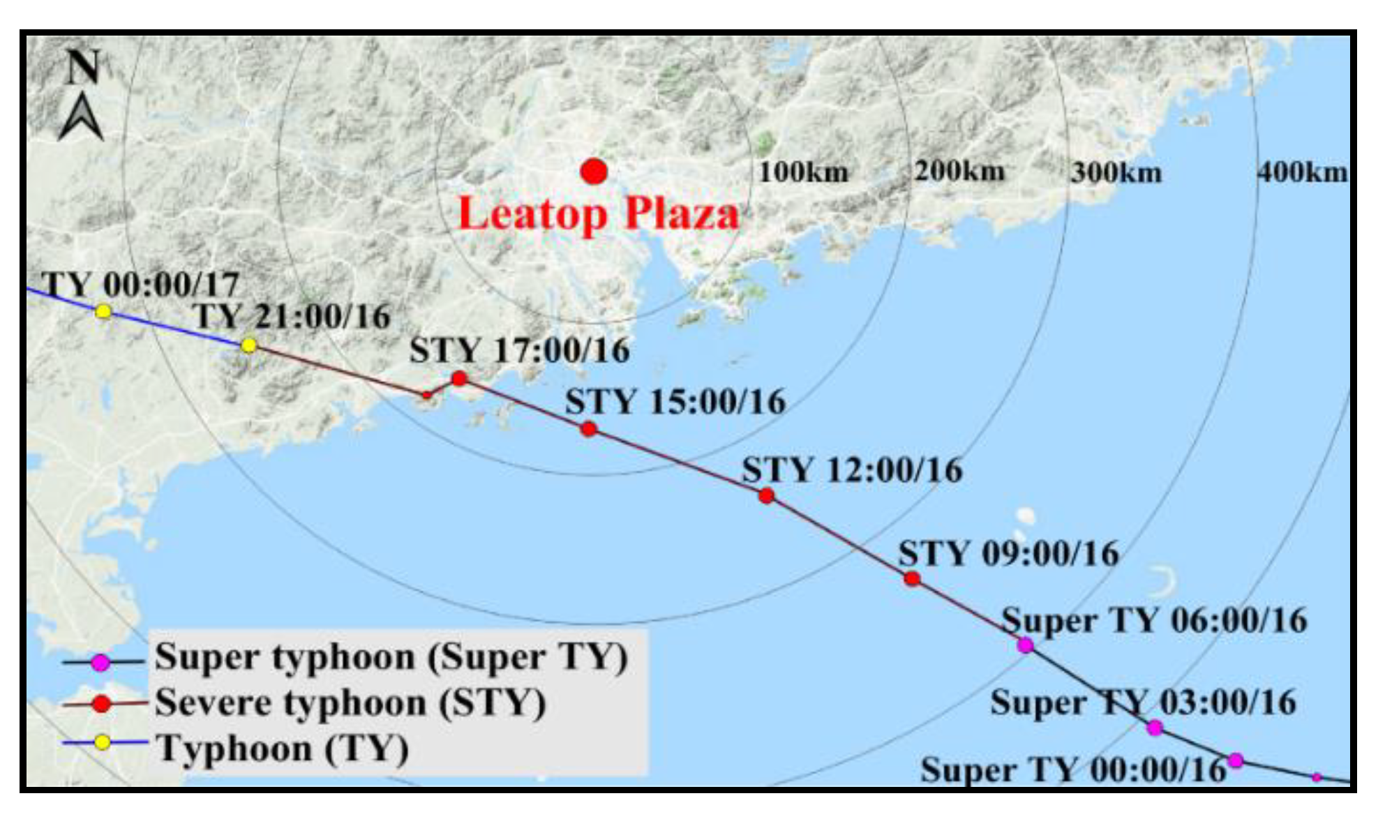
Mangkhut (1822) was one of the strongest tropical cyclones (TCs) to have ever attacked Guangdong of China in past decades. Figure 3 shows the best track of the typhoon. Mangkhut formed over the western North Pacific on 7 September 2018 and developed into a super typhoon on 11 September. After that, the vortex weakened as it crossed the northern part of Luzon and tracked northwestwards across the northern part of the South China Sea. Mangkhut weakened into a severe typhoon on the morning of 16 September and made landfall in the vicinity of Taishan of Guangdong. It then moved into the western part of Guangdong and weakened further until it disappeared in Guangxi province.
Mangkhut exerted severe impact on Guangzhou during its passage around this region. The largest gust wind speed recorded at a local meteorological station reached 50 m/s. In this study, field measurements from two observational sites are adopted to explore the typhoon wind characteristics: the one atop the Leatop Plaza tower and the other installed on the antenna of the Canton Tower, which is located at 2 km distance to the south of Leatop Plaza. Detailed information for the locations of the two sites is listed in Table 2.

3. Methodology Statement

3.1. Estimation of Structural Extreme Response

High-rise buildings subjected to strong wind excitations may vibrate excessively, which can result in comfort problems for occupants and other serviceability issues for relevant components or affiliated devices. Thus, it is conventionally required that the extreme response of building structures be restricted within an acceptable level [31,32]. Otherwise, associated measures should be implemented for vibration reduction and control of the dynamic systems [33,34,35,36].
In practice, the acceleration response is widely used as a preferred indicator for comfort/serviceability assessment of high-rise buildings, and many acceleration-response based criteria have been proposed, including those suggested in ISO 6897 [31], ISO 10137 [32], Melbourne and Palmer [37], JGJ 3-2010 [38], and AIJ-GEH-2004 [39]. Among these sources, the peak value of acceleration response is mostly utilized, although some recommend other alternatives, such as root-mean-square (RMS) value [9,10].
Statistically, the maximum acceleration response of a system A max can be estimated as:
A max = g σ a
where σ a is the standard-deviation response, and g is the peak factor. For a Gaussian process, g can be computed through up-crossing analysis [22]:
g = 2 ln ( v T ) + 0.5772 / 2 ln ( v T )
in which v is the up-crossing rate associated with a given period T (usually T = 600 s ) whose value can be calculated by:
v 2 = ( 0 f 2 S ( f ) d f ) / ( 0 S ( f ) d f )
in which f denotes natural frequency (Hz), and S ( f ) is the power spectral density (PSD) function. For high-rise buildings, since the first swaying-mode component often dominates the structural response, v can be roughly regarded as equal to the fundamental frequency of the building f c .
For narrow-band signals, σ a can be determined by using the frequency-domain method:
σ a = π 4 ξ · f 0 S F ( f 0 ) M 2
where ξ is the damping ratio, S F is the power spectrum of generalized force F ( t ) , while M is the generalized mass.
F ( t ) = 0 H f ( z , t ) μ ( z ) d z
M = 0 H m ( z ) μ ( z ) 2 d z
in which f ( z , t ) is the distributed wind force along height, μ ( z ) is the modal shape, and m ( z ) is distributed mass of the building along height.
The above equations indicate that the structural response depends on both the wind force f ( z , t ) and the modal parameters of the building (especially on ξ ). In wind engineering, wind-induced structural responses of high-rise buildings are conventionally determined via wind tunnel tests. Usually, only the first modal contribution of the structural response is taken into account, and the generalized force F ( t ) associated with the first mode can be measured directly based on the assumption that the mode shape is linear along height. If the first mode shape deviates from a linear pattern significantly, amendment should be conducted accordingly.

3.2. Identification of Modal Parameters Via SSI Method

Modal parameters (e.g., natural frequencies, damping ratios, and mode shapes) are usually involved as prerequisite information for many studies and practices. Thus, identification of modal parameter has gained extensive researching attention.
Many methods have been developed for the identification of modal parameters, such as peak-pick method and random decrement techniques (RDT) [22,24]. Among these methods, the Stochastic Subspace Identification (SSI) method is an advanced time-domain method that has been widely applied in recent years. This method has the ability to identify modal frequency, mode shape, and damping ratio of multiple modes of the system simultaneously, making it pretty efficient. Details about the SSI method can be referred to in [40]. This study only briefly introduces its methodology.
The dynamics of a structure subjected to ambient excitation can be depicted by the following discrete state-space model:
{ x k + 1 = A x k + B u k + w k y k = C x k + D u k + v k
where x k is the state vector, y k is the response data of the system, u k represents the input vector at the sampling time, and w k , v k are the process noise and the measurement noise, respectively. The sub-indices denote the time number, which is correlated with time through t = ( k 1 ) / f s , where f s is the sampling frequency. A is the discrete state matrix, which represents all the dynamic characteristics of the system, B is the discrete input matrix, C is the output matrix, and D is the direct transmission matrix.
For simplification, the two items w k , v k in Equation (7) can be regarded as two independently stationary zero-mean white-noise processes with the covariance matrix expressed as:
E [ ( w i v i ) ( w j T v j T ) ] = ( Q S S T R ) δ i j
where E is the mathematical expectation operator, δ i j is the Kronecker function whose value equals to one for i = j and to zero for i j . w i and w j are the input noises at moment i and j . v i and v j are the measurement noises at moment i and j , respectively, and Q , S , a n d R belong to covariance matrices.
To implement the SSI method, the so-called Hankel matrix should be constructed first based on output records. The block Toeplitz matrix can be then obtained by calculating the output covariance sequence. Finally, the state matrix A can be computed via singular value decomposition (SVD) from the block Toeplitz matrix.
Conducting eigenvalue decomposition operation on A :
A = ψ Λ ψ 1
where Λ is the eigenvalue diagonal matrix associated with the discrete-time system, whose non-zero elements are complex values λ , and ψ is the discrete-time eigenvector matrix.
According to the relationship between the eigenvalues associated respectively with the discrete-time system λ c and the continuous-time system λ , one has:
λ c = ln λ / Δ t = ξ ω ± j ω 1 ξ
where ξ , ω represent damping ratio and natural frequency, respectively, and Δ t represents sampling interval.
Based on the above equation, the model parameters (natural frequency, damping ratio, mode shape) of the system can be determined:
f = a 2 + b 2 2 π ,     ξ = a a 2 + b 2 ,     Φ = C ψ
where a , b represent the real and the imaginary parts of the eigenvalue, respectively.
It is worth noting that the mode order n of the system is involved as a key parameter in the above modal identification process. Misestimation of n may result in intractable problems in the final results, such as false modes or mode absence. Currently, there is no method for robust determination of the accurate value of n, but the stability diagram method is widely adopted as an effective way to estimate the computational mode order.
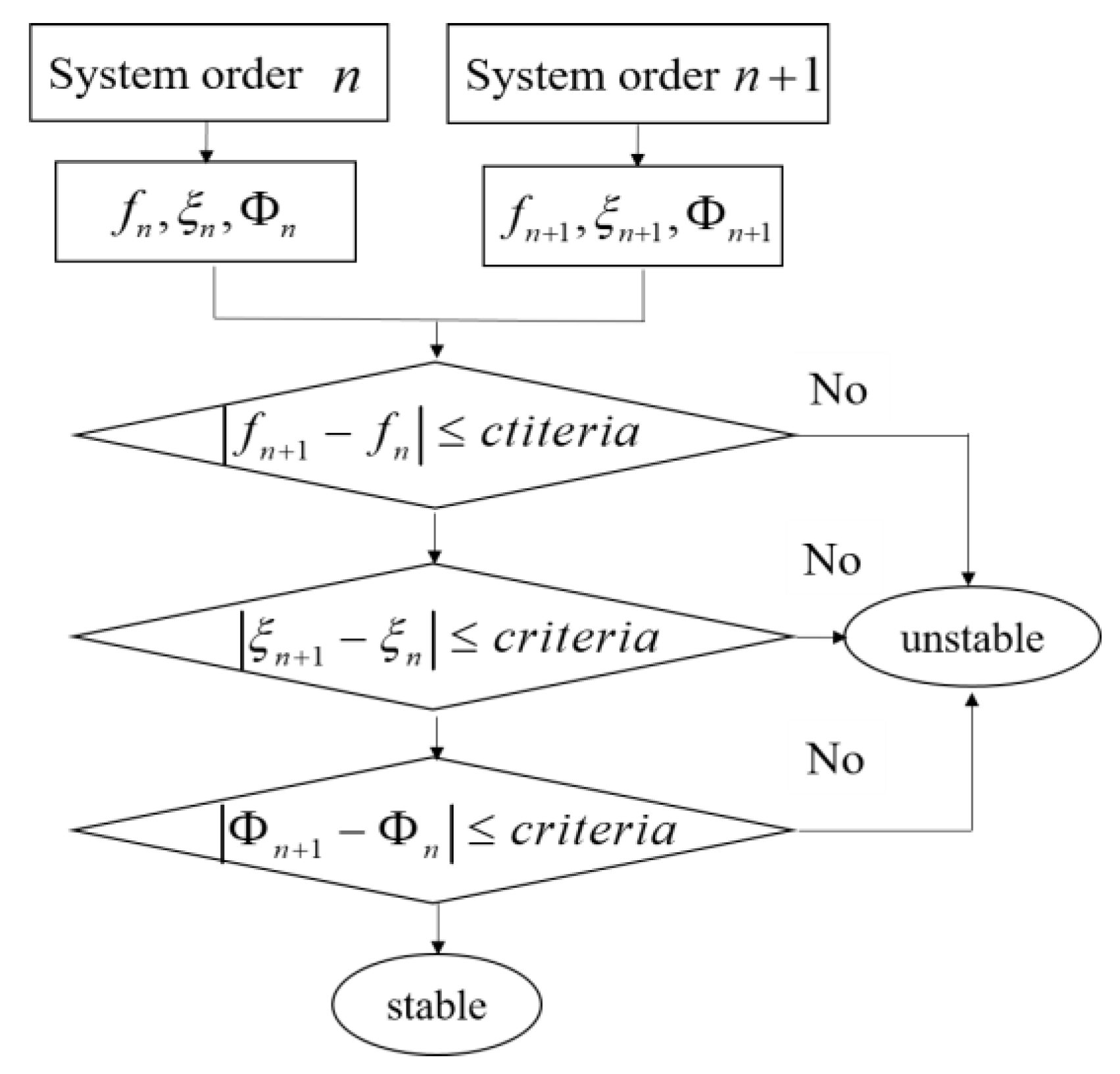
The stability diagram method assumes that the system has a series of computational mode orders whose values are continuous within a certain range. The nominal modal parameters associated with differed mode orders can be then computed using the aforementioned SSI method. If the difference between the identified modal parameters with the current computational mode order n and its next n + 1 is less than a preset critical value, the current state point is called a stability point, which constitutes the stability poles in the associated stability diagram. Figure 4 shows an implementation flow of the stability diagram method.

3.3. Random Decrement Technique

Random decrement technique (RDT) is an effective way to estimate the amplitude dependence of modal parameters. The response of a single-degree-of-freedom (SDOF) system consists of three components, i.e., the free attenuation caused by the initial displacement and the initial velocity, and the forced response caused by the random excitation:
x ( t ) = x x 0 + x x ˙ 0 + x F ( t )
where x x 0 and x x ˙ 0 respectively represent the response components associated with initial displacement x 0 and initial velocity x ˙ 0 , and x F ( t ) stands for the component associated with external input force at time instant t . In practice, since acceleration responses are more available, the response in Equation (12) can be equally treated as the acceleration response for easy application, given that the acceleration response signals account for the SDOF system. Accordingly, x x ˙ 0 tends to be the first-order derivative of acceleration response at x 0 .
By averaging multiple time periods response with the specified duration τ under the same initial conditions, the so-called random decrement (RD) signature can be obtained:
a ( x ^ ; τ ) = E { sgn [ x ( t ) ] x ( t + τ ) | x ˙ ( t ) = 0 , x ( t ) = x ^ }
where E { ( | C ) } is the conditional expectation under the condition C , and sgn [ ] stand for sign function. τ is an appointed time duration, which is also the length of a , and x ˙ ( t ) = 0 , x ( t ) = x ^ , are the conditions. Considering that the input process is a zero-mean static random state, both the forced vibration response contribution and the one due to initial velocity involved in the signature should turn to zero, only leaving the contribution due to initial displacement.
a ( τ ) = E [ sgn ( x ^ ) x ^ ] e ξ ω 0 τ × ( cos 1 ξ 2 ω 0 τ + ξ 1 ξ sin 1 ξ 2 ω 0 τ )
The natural frequency and the damping ratio for this SDOF system can be estimated by fitting the measurement records with Equation (14), or, alternatively, by fitting the envelope of the decay curve of the RD signature:
a ( τ ) = E [ sgn ( x ^ ) x ^ ] e ξ ω 0 τ
where ω 0 , ξ are natural frequency and damping ratio, respectively.

4. Results and Discussion

4.1. Typhoon Wind Characteristics

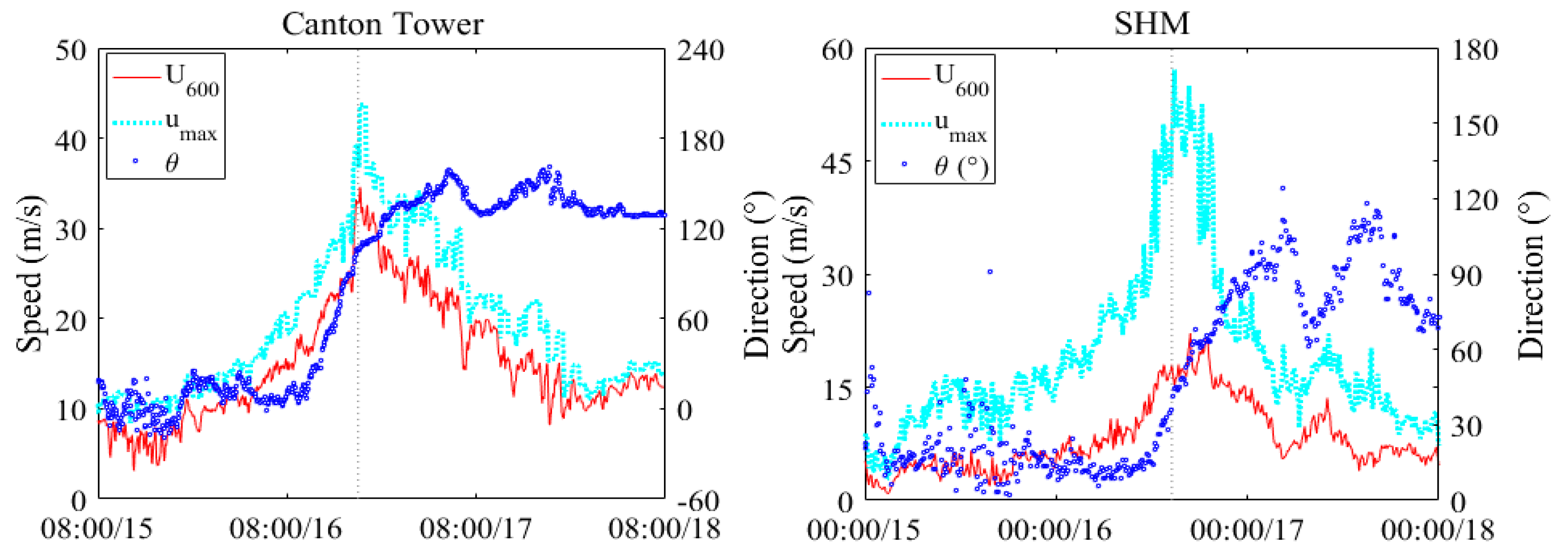
The time histories of 10 min mean wind speed and direction as well as three second peak gust in each 10 min duration at the two aforementioned meteorological stations are shown in Figure 5. As reflected, results at the two stations differ markedly. The maximum peak gusts at the Canton Tower were 43.8 m/s compared with the one of 56.5 m/s at Leatop Plaza. Basically, the mean speeds at the study building were much lower than those at the Canton Tower, while the peak gusts at many episodes from the study building were noticeably larger than those at the other site, which makes the gust factor values at Leatop Plaza considerably larger than those at the Canton Tower. Measurements of mean wind direction at the two sites also differed with each other significantly. The above discrepancies were mainly attributed to the fact that the study building is located at the CBD area of Guangzhou, where there exist many super-tall buildings which are comparable to or even taller than Leatop Plaza. Thus, wind flows around the study building were considerably turbulent. By contrast, the anemometer at Canton Tower is installed at a height of 532 m, where wind flows were less affected by the urban canopy. Despite these discrepancies, results of wind speed and direction at both sites demonstrate a similar changing trend, which is consistent with the evolution of distance between Mangkhut and Guangzhou.

4.2. Structural Response and Comfort Assessment

4.2.1. Structural Response

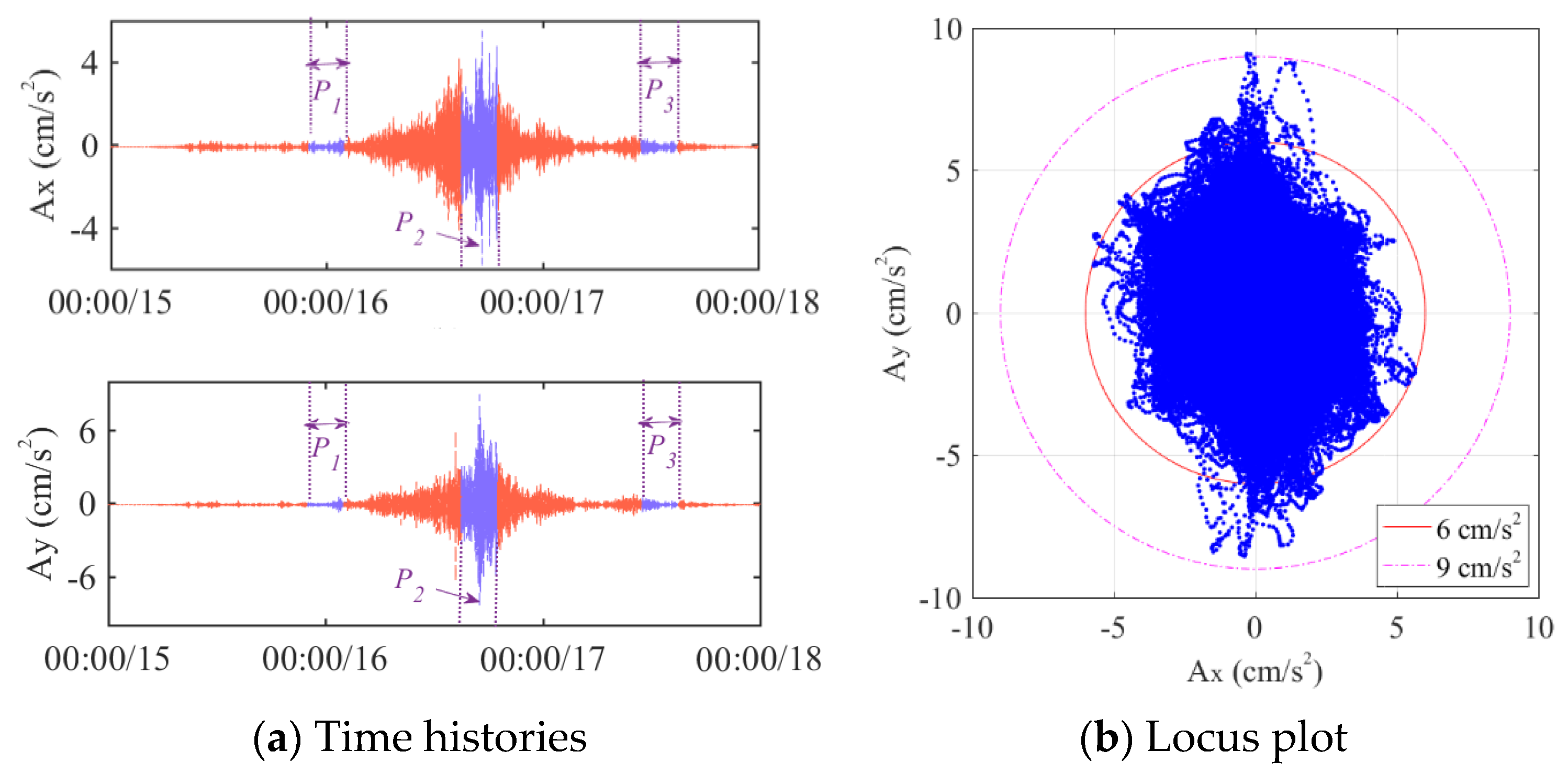
The time histories of acceleration response at the 58th floor are depicted in Figure 6a. According to the evolutions of wind strength around the study site, three episodes during the passage of Mangkhut are selected for detailed studies in the following parts: typhoon approaching period (22:00/15–02:00/16), nearest period (15:00/16–19:00/16), and leaving period (11:00/17–15:00/17), which, for short, are denoted as Period 1, Period 2, and Period 3, respectively. A balance between data size and stationarity of signals was considered for determining the duration of these periods.
Comparison of Figure 5 and Figure 6a demonstrates that the structural response evolved in a consistent way with the evolution of wind strength at the study site. The maximum accelerations along the two measurement directions were respectively recorded as 5.82 cm/s2 and 8.98 cm/s2. Figure 6b depicts the locus plot in Period 2, which provides a straightforward demonstration of the resultant response of the building.
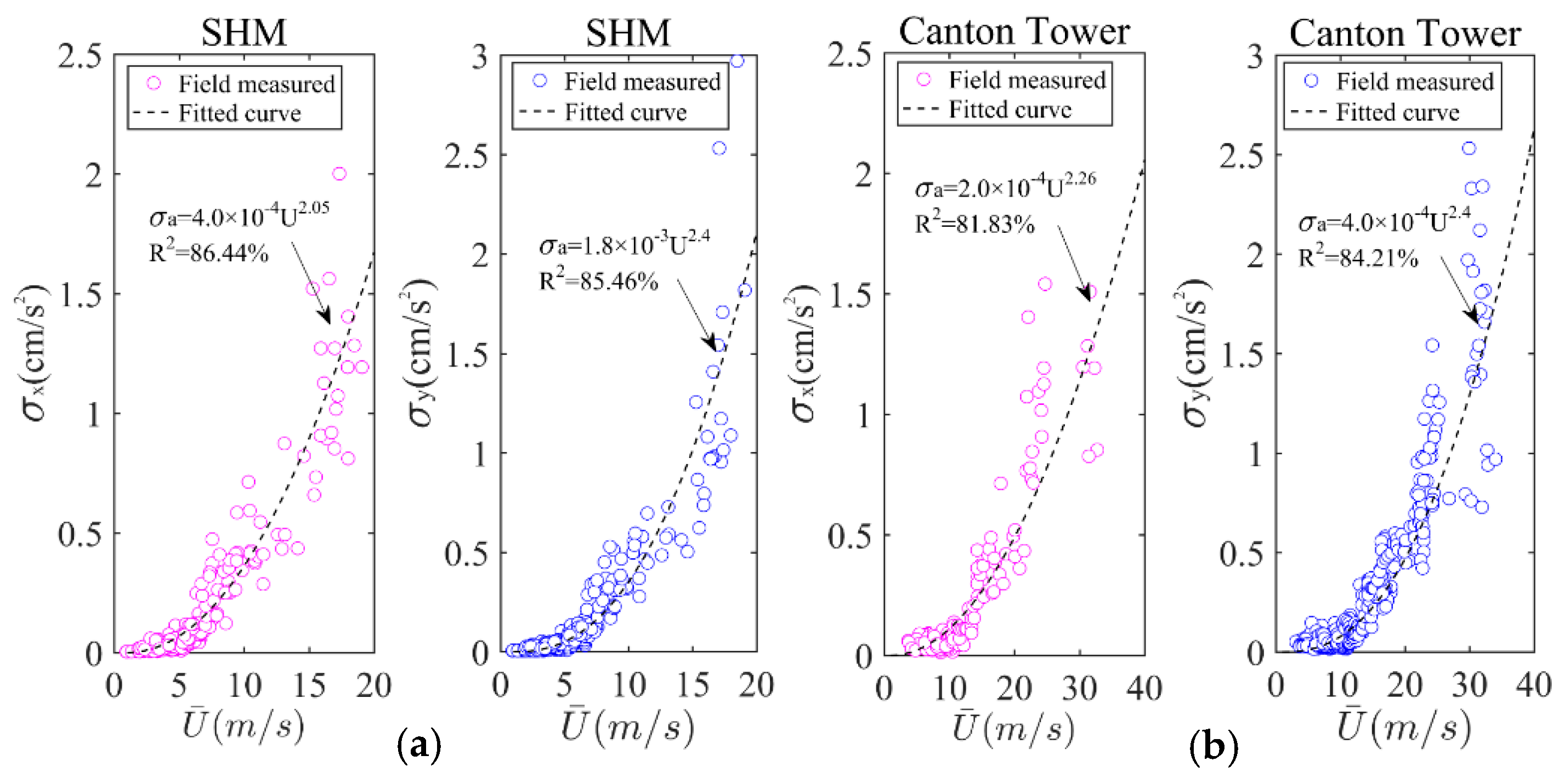
To quantify the correlation between the structural response and the wind speed, Figure 7 exhibits the standard deviations of acceleration and the mean wind speed over each 10 min duration. The following regression model was utilized to fit the measurements:
σ a = c 1 U c 2
where c 1 and c 2 are two coefficients.
As can be seen, the structural response increased in an exponential manner with increasing wind speed. The power exponents are recognized as 2.05–2.40, which are much larger than those reported in [22] where records of surface wind were adopted.

4.2.2. Peak Factor and Conform Assessment

According to Equation (1), the peak response value correlates with the standard deviation (SD) of response linearly with the correlation coefficient equal to the peak factor. As the peak factor can be calculated directly based on the natural frequency for SDOF cases, the peak response can be predicted from the SD values via the peak factor method.
To examine the validity of the above method, Table 3 compares the measured peak factor values with those calculated via Equation (2) during the three selected periods. It is seen that the two results basically agree with each other. The difference is largely attributed to the fact that response measurements do not strictly follow a Gaussian distribution, or, equally, the basic assumption for the derivation of Equation (2) was not satisfied so well.
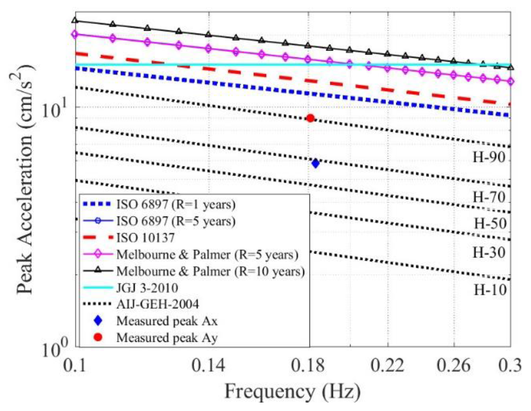
Figure 8 compares the measured maximum responses in the two directions (X: 5.82 cm/s2, Y: 8.98 cm/s2) at the 58th floor of Leatop Plaza against the comfort criteria from the five aforementioned reference sources. As demonstrated, although Typhoon Mangkhut was one of the strongest typhoons that ever impacted the study region, the maximum acceleration responses at the top of the building were still restrained within the recommended range. It must be noted that even the comfort criterion was well satisfied; according to the criteria of AIJ-GEH-2004 [39], there would be nearly 90% of occupants who could perceive the structural accelerations during the typhoon.

4.3. Identification of Modal Parameters

4.3.1. Natural Frequency and Damping Ratio

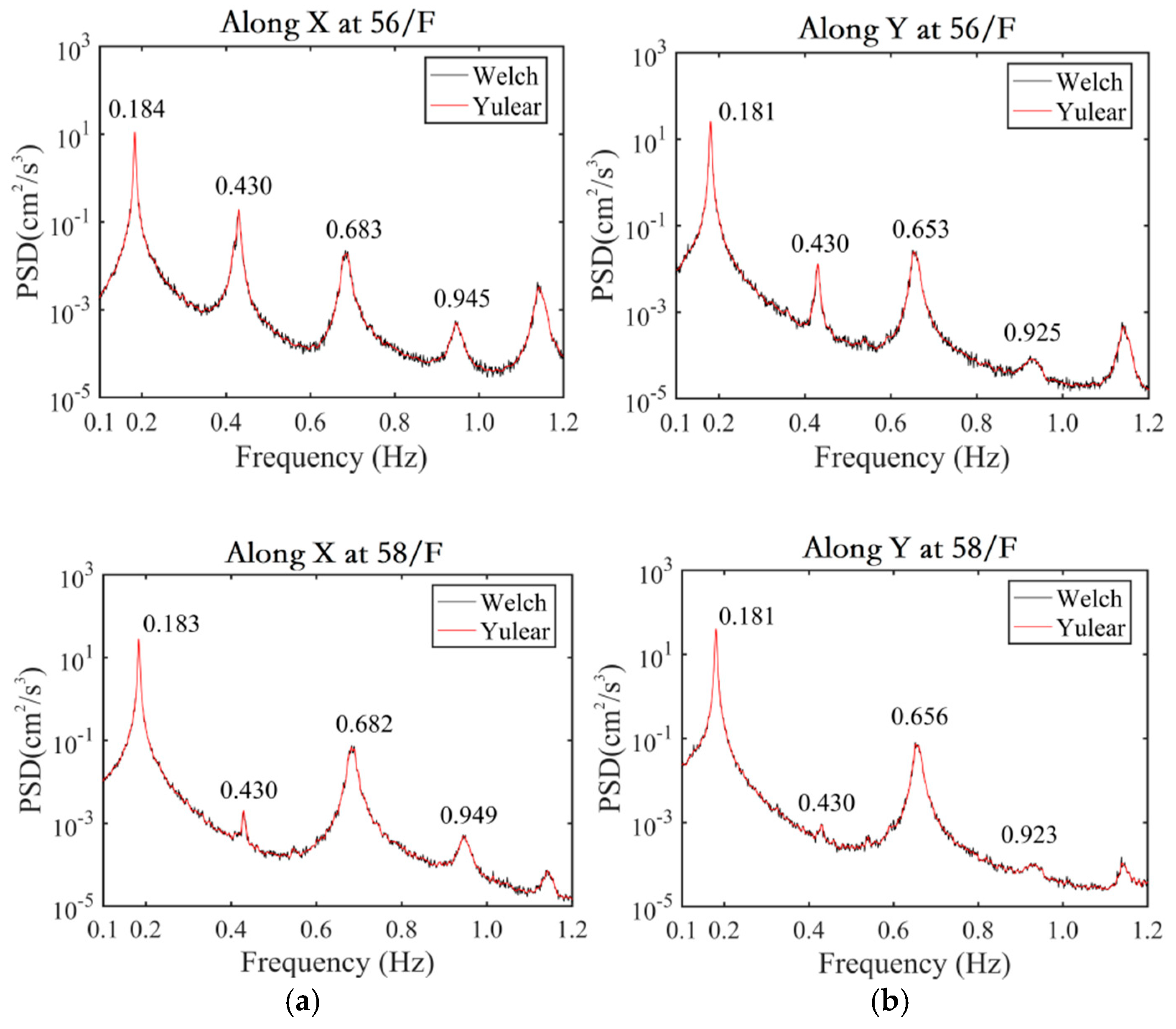
Figure 9 shows the PSD results based on the acceleration response at the 56th and the 58th floors during 15:00–19:00/16. In this study, both the Welch approach and the Yule–Walker technique are adopted to estimate the PSD. The block length for the Fast Fourier Transform (FFT) analysis involved in the Welch method was set as 214 = 16384 to provide a frequency resolution finer than 0.001 Hz (actually 0.000977 Hz), and the order for the Yule–Walker method was taken as 1000. From Figure 9, the results estimated via the two methods show good agreement, which indicates that the estimation processes were conducted effectively.
The results at the 56th floor show that there exist three evident PSD peaks in the frequency range below 0.8 Hz. However, the sharp peak around 0.430 Hz at the 56th floor turned out to be considerably subtle for the case at the 58th floor. From Table 1, the accelerometer at the 58th floor was placed around the centroid of the cross section, while the one at the 56th floor was placed far away from it. Thus, the accelerometer at the 58th floor was hardly able to measure response components of the torsional modes. Based on the above discussions, it is clear that the mode associated with 0.430 Hz belongs to a torsional type, while others belong to a swaying type.
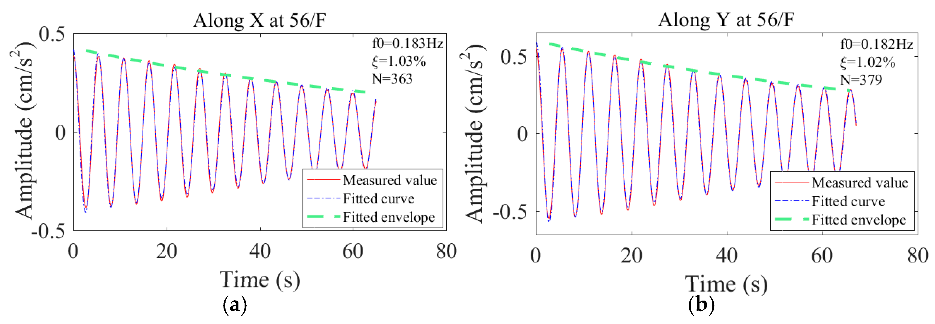
The RDT method is then utilized to estimate the damping ratio for different modes based on SDOF response components that are separated from the acceleration signals via band-pass filtering. Figure 10 exhibits associated results for the first swaying mode at the 56th floor. The damping ratios for the modes along the two measurement directions are estimated to be 1.03% and 1.02%, respectively.
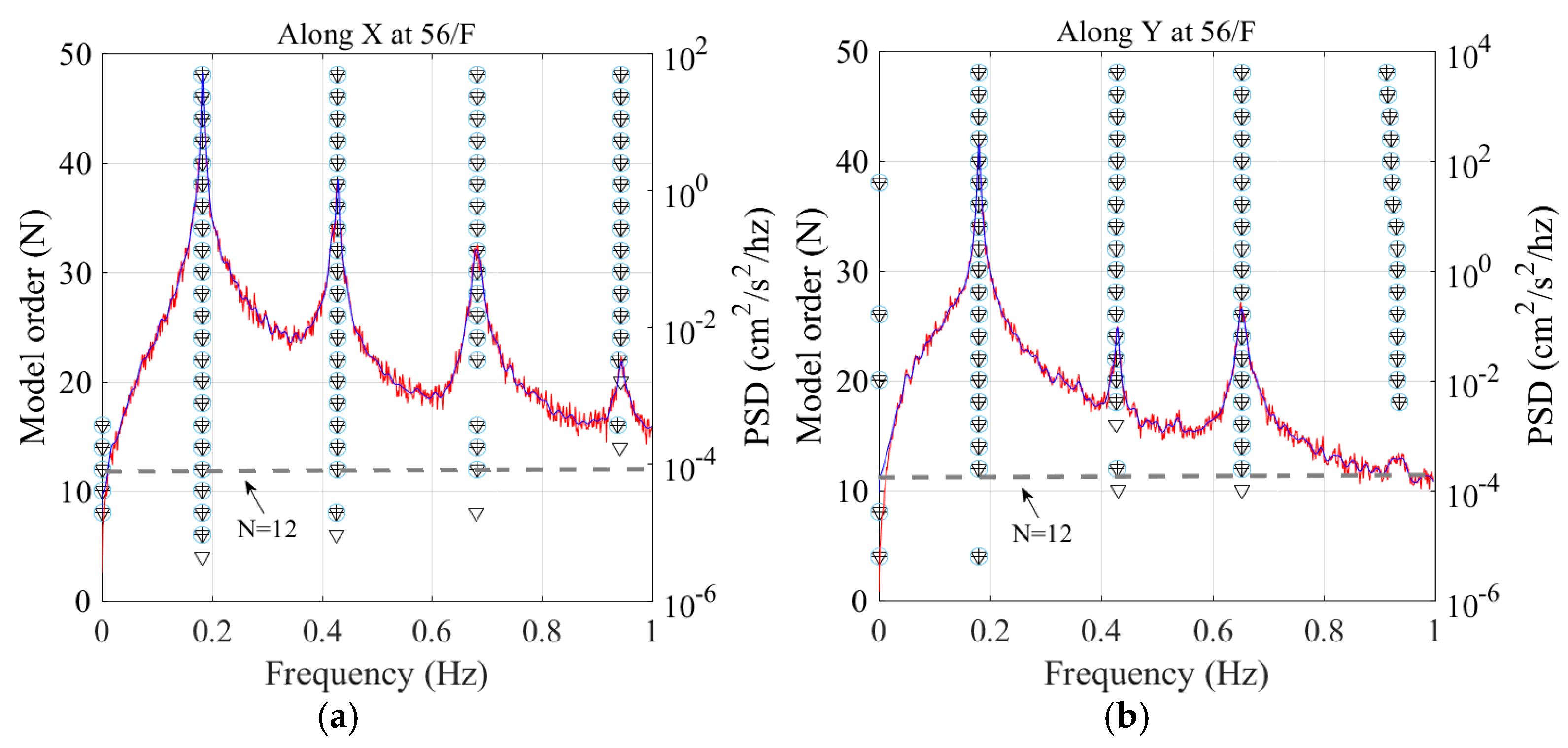
The SSI method is further adopted to estimate the modal parameters of Leatop Plaza. As discussed previously, the stability diagram method is used to evaluate the computational mode order with the involved critical values determined through a trial-and-error method as follows: 0.01 for natural frequency, 0.05 for damping ratio, and 0.90 for mode shape. Figure 11 shows the stability diagram overlaid by associated PSD results at the 56th floor. As reflected, there are three robust stable-axes in the range below 0.8 Hz, and the corresponding frequencies agree well with the natural frequencies obtained via the peak-picking method based on the PSD results. The computational mode order can be then selected as six, which is half of the nominal mode order as marked in the figure. Table 4 compares the identification results of the natural frequencies and the damping ratios via both the SSI method and the RDT method. Basically, the two kinds of results show acceptable agreement. It is noted that it is very different to estimate the damping ratios accurately based on output-only records, and large fluctuation may exist even for the case by using the same method but based on different episodes of records.
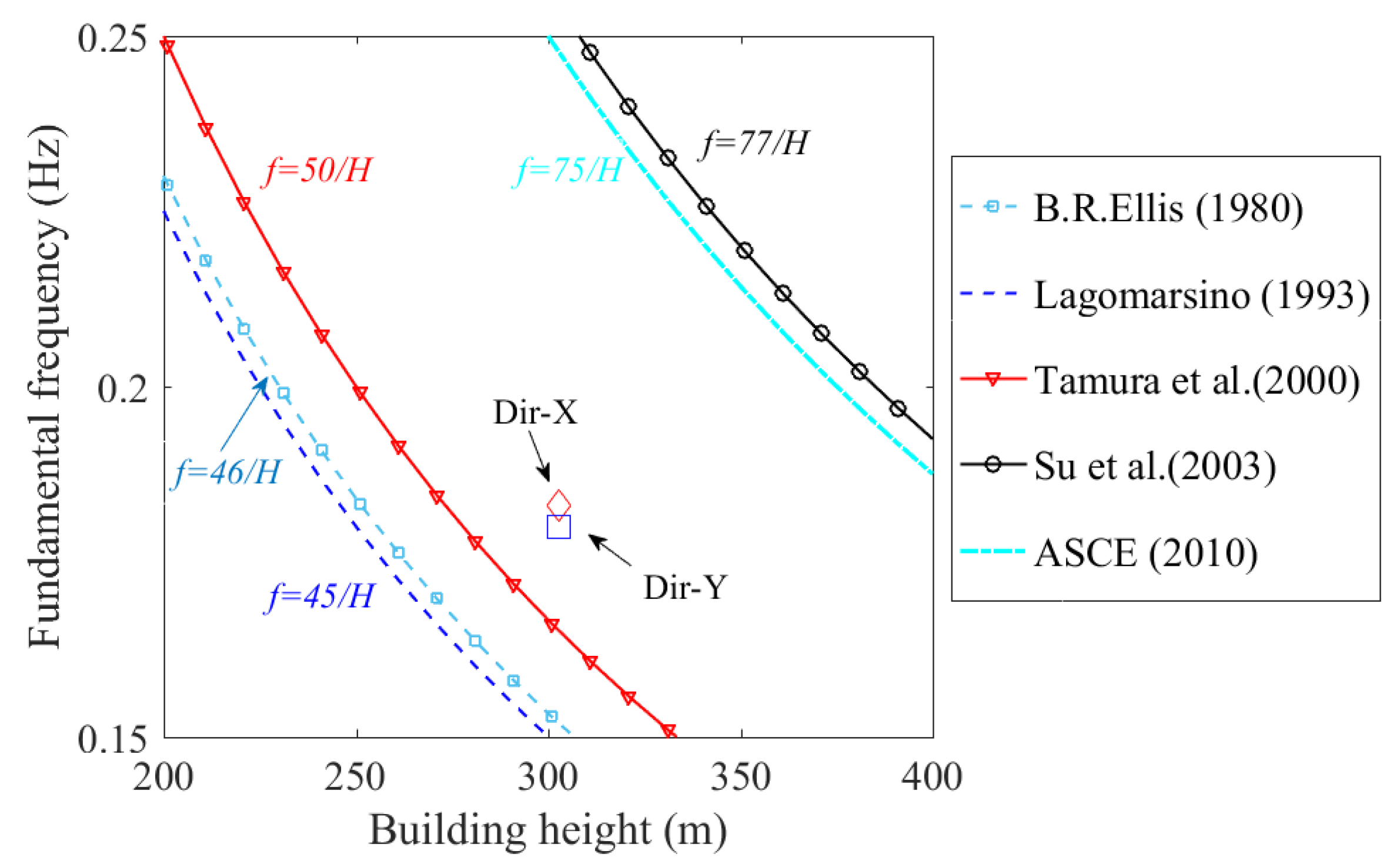
In wind engineering, the modal parameters are often estimated via certain empirical predictors at the design stage of building structures. These empirical predictors are generally established based on statistical analysis of database of identified modal parameters through field measurements [41,42,43,44,45]. Since the damping ratios are usually scattered severely around the recommended predictors in associated literature, this part only considers comparing the results of natural frequency from measurement with those estimated via corresponding predictors. Figure 12 plots the measured fundamental natural frequencies along the two measurement directions against the estimations via the predictors suggested in five reference sources [41,42,43,44,45]. The measured results agree best with those estimated via the predictor in [43], which suggests the fundamental natural frequency is equal to 50/H, H being the height of the building.

4.3.2. Amplitude-Dependence of Natural Frequency and Damping Ratio

Although natural frequencies and damping ratios are conventionally regarded as constant for a given mode of the studied dynamic system, results from numerous field studies reveal that the values of these parameters may vary noticeably with the vibration amplitude of building structures [22]. The amplitude-dependence of modal parameters, particularly of the damping ratio, sheds new light on the intrinsic properties of the buildings’ dynamics.
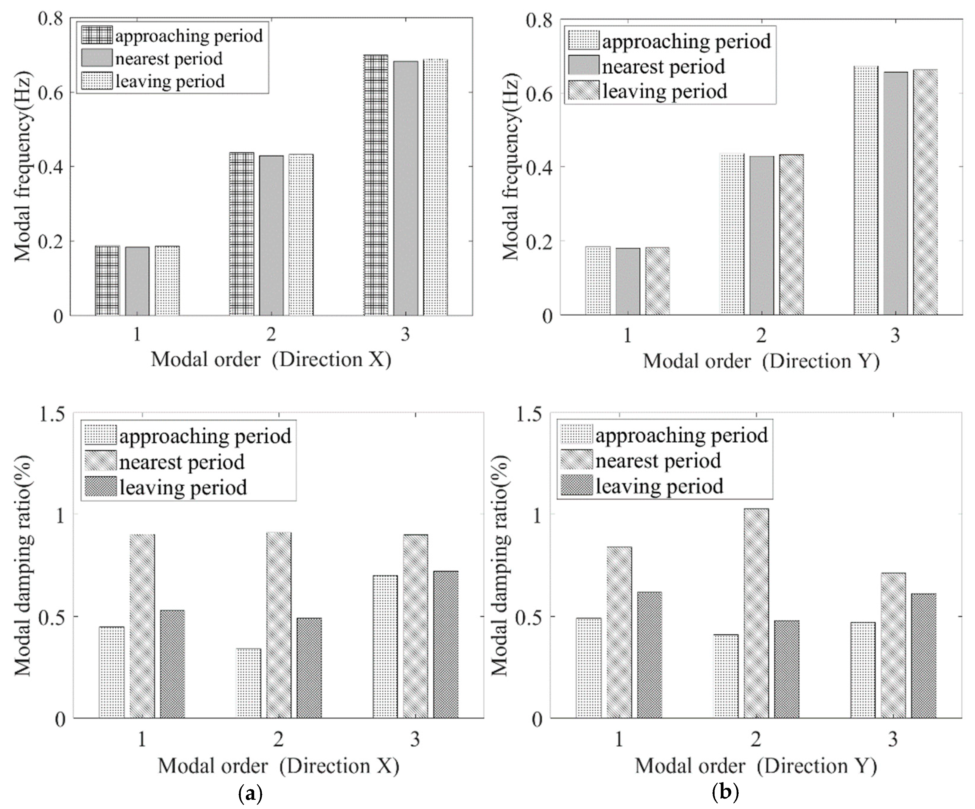
Figure 13 and Table 5 show the values of natural frequency and damping ratio for the first three modes along the two measurement directions via the SSI method based on field records collected at the 56th floor during the three selected periods. As expected, the values of natural frequency and damping ratio for the same mode varied among different periods. The natural frequencies decreased slightly, while the damping ratios increased significantly when the typhoon got nearest to the study site and the building vibrated most severely. By contrast, when the typhoon moved far away from the study site and the building vibrated moderately, the natural frequencies increased while the damping ratios decreased, respectively.
Great efforts have been made to explore the mechanisms for the amplitude dependence of damping ratio. Typically, Jerry [46,47] proposed a three-staged model of damping ratio for building structures. According to this theory, at quite low amplitudes, only large structural components have relative motions, typically at junction points, and the damping at this stage is relatively stable and small. As the building’s vibration amplitude increases, increasingly more small units tend to participate in such relative movements. Accordingly, the damping increases continuously. Finally, when all possible mechanisms are activated, the damping remains constant, even throughout the increase of amplitude.
To further explore the amplitude-dependence of modal parameters, Figure 14 plots the variations of damping ratios and natural frequencies with continuously increasing acceleration response for the first swaying and torsional modes in the two orthogonal directions. As depicted, the natural frequencies decreased gradually with the increase of vibration amplitudes, from 0.185 to 0.175 Hz for the first swaying mode, from 0.435 to 0.425 Hz for the first torsional mode, and from 0.70 to 0.65 Hz for the second swaying mode. On the other hand, results of damping ratio demonstrated slight fluctuations, but an increasing trend could be observed when the amplitude reached a certain level, beyond which, the damping ratio values tended to level off. Overall, the damping ratios for both the swaying modes and the torsional mode were in a range of 0.5–1.2%, which were a bit smaller the typical value of 1.0–1.5% as recommended in codes and standards.

4.3.3. Mode Shapes

As discussed in the introduction section, a typical merit of modal identification based on multiple levels of records lies in the ability to determine mode shapes. The following forms are recommended in the national load code of China, i.e., GB50009-2012 [48], for depicting the mode shapes for the first swaying mode ϕ s 1 and the first torsional mode ϕ θ 1 , respectively:
ϕ s 1 = 6 z 2 H 2 4 z 3 H + z 4 3 H 4
ϕ θ 1 = ( z H ) 0.8
where z denotes height, and H stands for building height.
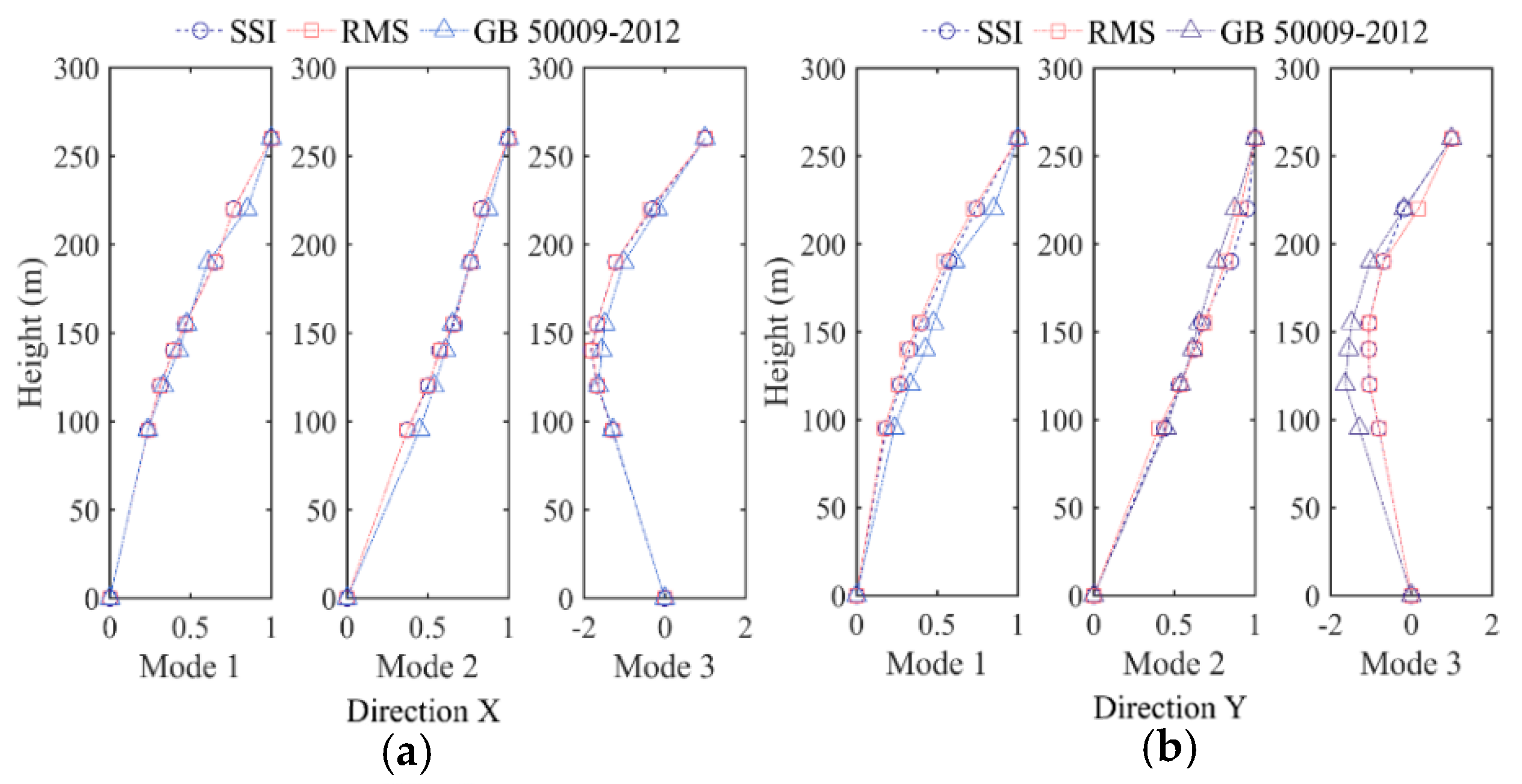
Figure 15 compares the measured mode shapes with those predicted by the above equations. Besides the SSI method, another method is also utilized to identify mode shapes based on field measurements, i.e., the RMS method, which assumes that the mode shapes can be quantified by the proportional relationship of root-mean-square values for the associated modal component at different testing points. From the figure, results obtained via different methods show good agreement, indicating the credibility of the adopted modal identification methods as well as the empirical predictors recommended in code. Note that the first swaying mode shape deviates from a linear pattern, which is against the basic assumption of linear distribution for the first mode shape involved in the high-frequency force balance (HFFB) wind tunnel tests. Thus, to obtain more accurate testing results, such nonlinear effects should be specially taken into account and compensated [49]. It is also observed that, for the Leatop Plaza building, which adopts a structural system consisting of a steel frame and a reinforced concrete core tube, the first swaying mode shape is convexly curved along height, while the first torsional mode shape is concaved.

4.4. Comparison with Finite Element Results

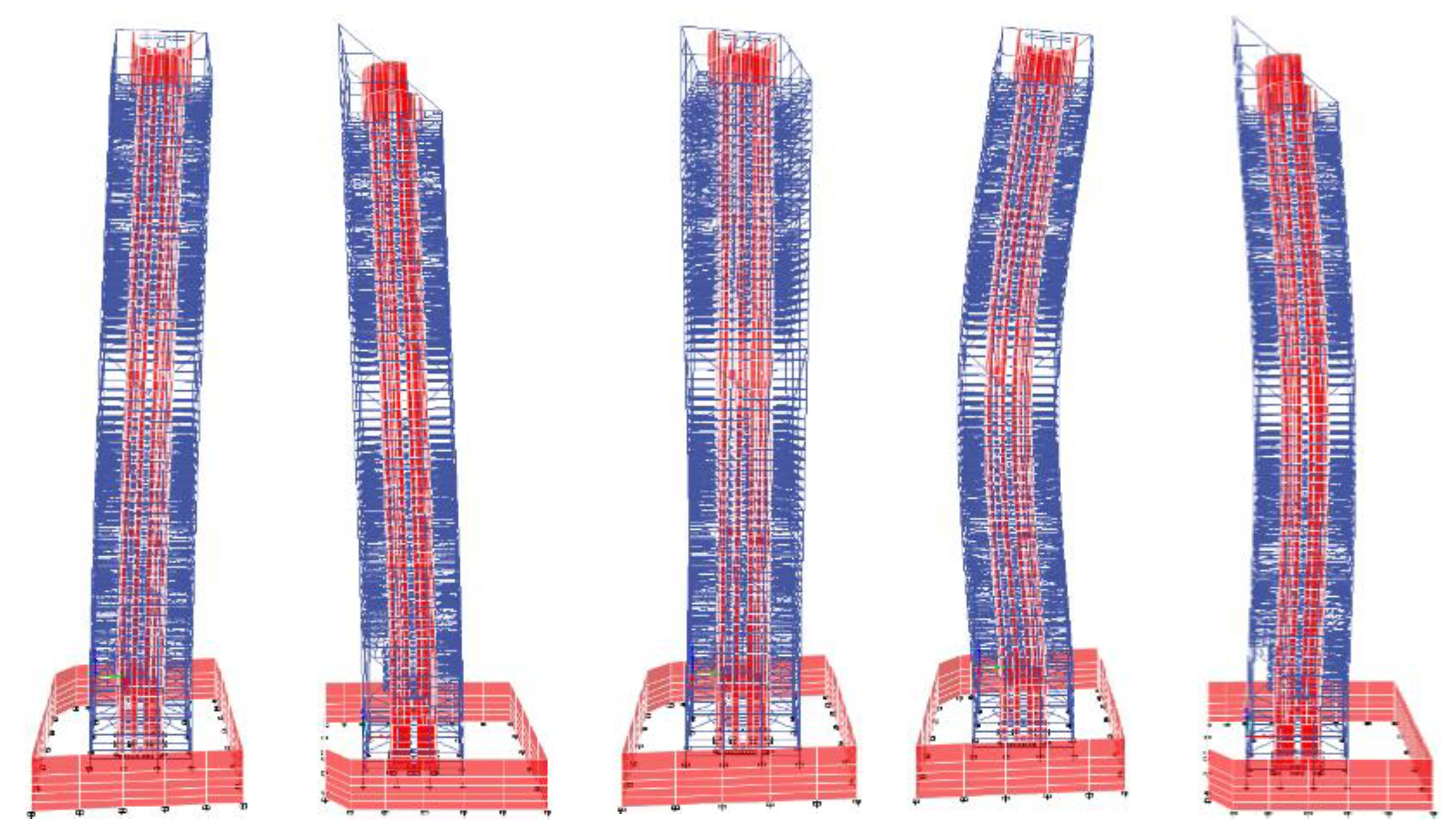
A finite element model is established via a beam-slab modeling method in accordance with the structural information of the studied building at its design stage. Twelve-node beam elements and four-node elastic plate elements are employed to model the main body of the structure, three-dimensional link elements are adopted to model the supporting components, and mass elements are used to model the live loads and the nonstructural components. Modal analysis is performed based on the established model via the ETABS software. Relevant results are shown in Figure 16 and Table 6.
Through comparison, the natural frequencies from simulations are found to be collectively lower than the measured values, with the maximum relative difference equal to 13.3%. The discrepancy may be attributable to the following potential reasons. (1) During the simulation process, the live loads for the building were overestimated with respect to real conditions, and the modal mass of the building model was overestimated correspondingly. (2) As the building was constructed, its stiffness may be increased slightly due to the contribution of non-structural components such as doors, windows, and walls, which were not taken into account during the numerical simulation. (3) Because the structure of the studied building is very complex, many uncertainties may exist in the numerical model, which tends to result in simulation errors. It is noted that such discrepancies were also reported in many previous studies [24,50]. However, more efforts are still required to explore the detailed reasons.
To examine the working performance of numerical simulation in term of mode shape, the modal assurance criterion (MAC) and the normalized modal difference (NMD) are adopted [24]:
M A C ( { ϕ i A } , { ϕ i B } ) = | { ϕ i A } T { ϕ i B } | 2 ( { ϕ i A ) T ϕ i A } ) ( { ϕ i B ) T ϕ i B } ) N M D ( { ϕ i A } , { ϕ i B } ) = 1 M A C ( { ϕ i A } , { ϕ i B } ) M A C ( { ϕ i A } , { ϕ i B } )
in which ϕ i A , ϕ i B denote the ith mode shape vectors from measurement and simulation, respectively. If MAC = 1, it means the two mode shapes are identical, while when MAC = 0, it indicates the two mode shapes are completely different. In contrast, a smaller NMD value indicates a better correlation between the two mode shape vectors.
Table 7 lists the values of MAC and NMD between the measured and calculated mode shapes. It can be observed that most of the MAC values are greater than 0.88, which indicates that the measured and simulated mode shapes show good agreement. It is also observed numerical simulation tends to provide less accurate prediction of mode shapes for higher order modes.

5. Conclusions

In this study, field measurements collected at multiple height levels of a 303 m high building during the passage of a severe typhoon were analyzed to explore the dynamic properties of and the associated wind effects on the building. The relationship between the structural response and the wind strength was examined. Comfort assessment was conducted by comparing the maximum acceleration response with recommendations from several reference sources. Emphasis was paid to the identification of modal parameters via different methods and their dependence upon wind strength or the amplitude of structural vibration. Main conclusions and discussions are summarized as follows.
(1)
Although Typhoon Mangkhut was one of the strongest tropical cyclones to have ever impacted the study region, and the maximum peak gust wind speed was recorded as 56.5 m/s at the study site, the maximum structural response at the top floor (260 m) of Leatop Plaza was only 8.98 cm/s2, which is well below the critical levels for conform assessment as recommended in several reference sources. Practically, one may use the peak factor method to predict the peak structural response based on SD values of building responses that can be easily estimated through wind tunnel testing techniques, given the values of peak factor and other modal information. In this study, the measured peak factors for the fundamental modal response were found in a range of 2.97–3.25, which are a bit lower than the theoretical values. The reason is mainly attributed to the fact that response signals deviate from a Gaussian distribution pattern. Thus, more advanced techniques may be adopted to better predict the values of peak factor. Measurement results also show that the SD values of building response increased exponentially with mean wind speed, with the power exponent equal to 2.05–2.40. This indicates that high-rise buildings are considerably sensitive to wind load.
(2)
Results of modal parameters identified via the SSI method and other alternative methods (including the RDT method and the RMS method) basically show good agreement, which indicates the validity and the accuracy of the adopted methods. However, it must be noted that the SSI method is much more efficient, since it can provide results of natural frequency, damping ratio, and mode shape for multiple modes simultaneously, while the alternative methods can be only employed to deal with SDOF problems. More importantly, the alternative methods should be used in conjunction with filtering techniques whose working performance may differ significantly with users depending upon their experience. Thus, the SSI method is regarded as a preferred method for modal analysis.
(3)
Both natural frequency and damping ratio demonstrated noticeable amplitude-dependence features. While the natural frequencies decreased slightly with increasing structural response, the damping ratios increased markedly as the structure response became stronger. For the first swaying mode, the measured damping ratios varied in a range of 0.4–1.2%, which is a bit smaller than the recommendations in many codes and standards. The above findings provide useful insights to explore the nonlinear dynamic properties of building structures.
(4)
The performance of five empirical predictors for natural frequency was examined, and the one proposed by Tamura et al. [43] was found to provide the best predictions for the study building. The performance of two empirical predictors for first swaying mode shape and first torsional mode shape were examined as well, results from both of which agreed well with those obtained from measurements. It is also observed that the first swaying mode shape did not follow a linear pattern, which is against the basic assumption of linear distribution for the first mode shape involved in the HFFB wind tunnel tests. Thus, amendment is required for such testing results.
(5)
The measured results were further compared with those through numerical simulations. It was found that the natural frequencies computed via the finite-element-method were consistently lower (on the order of 10%) than the measured values for the study building. Several possible reasons were discussed in the context.

Author Contributions

Z.L. (Zhi Li) and Y.H. designed the research method and finalized the manuscript; J.F., Z.L. (Zhen Liu) and J.W. designed, collected and analyzed data; R.R. and C.-T.N. contributed in the results and discussions; Y.H. revised the paper and provided the funding. All authors have read and agreed to the published version of the manuscript.

Funding

This work is financially supported by the National Natural Science Foundation of China with Grant No. 51878194, No. 51925802 and No. 11972123.

Conflicts of Interest

The authors declare no conflict of interest.

References

  1. Xiao, Y.F.; Duan, Z.D.; Xiao, Y.Q.; Ou, J.P.; Chang, L.; Li, Q.S. Typhoon wind hazard analysis for southeast China coastal regions. Struct. Saf. 2011, 33, 286–295. [Google Scholar] [CrossRef]
  2. Li, Q.S.; Li, X.; He, Y.C. Monitoring Wind Characteristics and Structural Performance of a Supertall Building during a Landfall Typhoon. J. Struct. Eng. 2016, 142, 04016097. [Google Scholar] [CrossRef]
  3. Liang, Q.S.; Fu, J.Y.; Li, Z.; Yan, B.W.; Shu, Z.R.; He, Y.C. Bimodal distribution of wind pressure on windward facades of high-rise buildings induced by interference effects. J. Wind Eng. Ind. Aerodyn. 2020, 200, 104156. [Google Scholar] [CrossRef]
  4. Yan, B.W.; Li, Q.S. Large-eddy simulation of wind effects on a super-tall building in urban environment conditions. Struct. Infrastruct. Eng. 2016, 12, 765–785. [Google Scholar] [CrossRef]
  5. Yan, B.W.; Li, Q.S. Detached-eddy and large-eddy simulations of wind effects on a high-rise structure. Comput. Fluids 2017, 150, 74–83. [Google Scholar] [CrossRef]
  6. Blocken, B. 50 years of computational wind engineering: Past, present and future. J. Wind Eng. Ind. Aerodyn. 2014, 129, 69–102. [Google Scholar] [CrossRef]
  7. Huang, S.H.; Li, R.; Li, Q.S. Numerical simulation on fluid-structure interaction of wind around super-tall building at high reynolds number conditions. Struct. Eng. Mech. 2013, 46, 197–212. [Google Scholar] [CrossRef] [Green Version]
  8. He, Y.H.; Li, Q.S.; Zhu, H.P.; Han, X.L.; He, Y.C.; Li, X. Monitoring of structural modal parameters and dynamic responses of a 600m-high skyscraper during a typhoon. Struct. Des. Tall Spec. Build. 2018, 6, e1456. [Google Scholar] [CrossRef]
  9. He, Y.H.; Han, X.L.; Li, Q.S.; Zhu, H.P.; He, Y.C. Monitoring of wind effects on 600 m high Ping-An Finance Center during Typhoon Haima. Eng. Struct. 2018, 167, 308–326. [Google Scholar] [CrossRef]
  10. Li, X.; Li, Q.S. Observations of typhoon effects on a high-rise building and verification of wind tunnel predictions. J. Wind Eng. Ind. Aerodyn. 2019, 184, 174–184. [Google Scholar] [CrossRef]
  11. Huang, Y.J.; Gu, M.; Huang, Z.F. Field Measurements of Dynamic Properties of a Supertall Building during Construction of an Adjacent Supertall Building. J. Struct. Eng. 2019, 145, 04019121. [Google Scholar] [CrossRef]
  12. Zhang, J.W.; Li, Q.S. Identification of modal parameters of a 600-m-high skyscraper from field vibration tests. Earthq. Eng. Struct. Dyn. 2019, 48, 1678–1698. [Google Scholar] [CrossRef]
  13. Zhang, J.W.; Li, Q.S. Wind tunnel test and field measurement study of wind effects on a 600-m-high super-tall building. Struct. Des. Tall Spec. Build. 2019, 26, e1385. [Google Scholar] [CrossRef]
  14. He, Y.C.; Liu, Z.; Li, Z.; Wu, J.R.; Fu, J.Y. Modal identification of a high-rise building subjected to a landfall typhoon via both deterministic and Bayesian methods. Math. Biosci. Eng. 2019, 16, 7155–7176. [Google Scholar] [CrossRef]
  15. Kijewski-Correa, T.; Kilpatrick, J.; Kareem, A.; Kwon, D.K.; Bashor, R.; Kochly, M.; Morrish, D. Validating wind-induced response of tall buildings: Synopsis of the Chicago full-scale monitoring program. J. Struct. Eng. 2006, 132, 1509–1523. [Google Scholar] [CrossRef] [Green Version]
  16. Kijewski-Correa, T.; Pirnia, J.D. Dynamic behavior of tall buildings under wind: Insights from full-scale monitoring. Struct. Des. Tall Spec. Build. 2007, 16, 471–486. [Google Scholar] [CrossRef]
  17. Kijewski-Correa, T.; Kwon, D.K.; Kareem, A.; Bentz, A.; Guo, Y.; Bobby, S.; Abdelrazaq, A. SmartSync: An integrated real-time structural health monitoring and structural identification system for tall buildings. J. Struct. Eng. 2013, 139, 1675–1687. [Google Scholar] [CrossRef] [Green Version]
  18. Wu, J.R.; Liu, P.F.; Li, Q.S. Effects of amplitude-dependent damping and time constant on wind-induced responses of super tall building. Comput. Struct. 2007, 85, 1165–1176. [Google Scholar] [CrossRef]
  19. Fu, J.Y.; Li, Q.S.; Wu, J.R.; Xiao, Y.Q.; Song, L.L. Field measurements of boundary layer wind characteristics and wind-induced responses of super-tall buildings. J. Wind Eng. Ind. Aerodyn. 2008, 96, 1332–1358. [Google Scholar] [CrossRef]
  20. Fu, J.Y.; Wu, J.R.; Xu, A.; Li, Q.S.; Xiao, Y.Q. Full-scale measurements of wind effects on Guangzhou West Tower. Eng. Struct. 2012, 35, 120–139. [Google Scholar] [CrossRef]
  21. Au, S.K.; Zhang, F.L.; To, P. Field observations on modal properties of two tall buildings under strong wind. J. Wind Eng. Ind. Aerodyn. 2012, 101, 12–23. [Google Scholar] [CrossRef]
  22. He, Y.C.; Li, Q.S. Dynamic responses of a 492-m-high tall building with active tuned mass damping system during a typhoon. Struct. Control. Health Monit. 2014, 21, 705–720. [Google Scholar] [CrossRef]
  23. He, Y.C.; Li, Q.S. Time–frequency analysis of structural dynamic characteristics of tall buildings. Struct. Infrastruct. Eng. 2015, 11, 971–989. [Google Scholar] [CrossRef]
  24. Li, Q.S.; Zhi, L.H.; Tuan, A.Y.; Kao, C.S.; Su, S.C.; Wu, C.F. Dynamic behavior of Taipei 101 tower: Field measurement and numerical analysis. J. Struct. Eng. 2011, 137, 143–155. [Google Scholar] [CrossRef] [Green Version]
  25. Li, Q.S.; He, Y.C.; He, Y.H.; Zhou, K.; Han, X.L. Monitoring of wind effects of a landfall typhoon on a 600 m high skyscraper. Struct. Infrastruct. Eng. 2019, 15, 54–71. [Google Scholar] [CrossRef]
  26. Li, Q.S.; Li, X.; He, Y.C.; Yi, J. Observation of wind fields over different terrains and wind effects on a super-tall building during a severe typhoon and verification of wind tunnel predictions. J. Wind Eng. Ind. Aerodyn. 2017, 162, 73–84. [Google Scholar] [CrossRef]
  27. Zhou, K.; Li, Q.S.; Li, X. Dynamic behavior of supertall building with active control system during Super Typhoon Mangkhut. J. Struct. Eng. 2020, 5, 04020077. [Google Scholar] [CrossRef]
  28. Wu, J.; Xu, H.J.; Zhang, Q.L. Dynamic performance evaluation of Shanghai Tower under winds based on full-scale data. Struct. Des. Tall Spec. Build. 2019, 28, e1611. [Google Scholar] [CrossRef]
  29. Wang, C.Q.; Li, Z.N.; Luo, Q.Z.; Hu, L.; Zhao, Z.F.; Hu, J.X.; Zhang, X.W. Wind characteristics investigation on the Roofs of three adjacent high-rise buildings in a coastal area during Typhoon Meranti. Appl. Sci. 2019, 9, 367. [Google Scholar] [CrossRef] [Green Version]
  30. Li, Z.N.; Hu, J.X.; Zhao, Z.F.; Wang, C.Q. Dynamic system identification of a high-rise building during Typhoon Kalmaegi. J. Wind Eng. Ind. Aerodyn. 2018, 181, 141–160. [Google Scholar] [CrossRef]
  31. ISO 6897. Guidelines for the Evaluation of the Response of Occupants of Fixed Structures, Especially Buildings and Off-Shore Structures, to Low Frequency Horizontal Motion (0.063 to 1 Hz); International Organization for Standardization: Geneva, Switzerland, 1984. [Google Scholar]
  32. ISO 10137. Bases for Design of Structures-Serviceability of Buildings and Walkways Against Vibrations; International Organization for Standardization: Geneva, Switzerland, 2007. [Google Scholar]
  33. Pnevmatikos, N.G.; Thomos, G.C. Stochastic structural control under earthquake excitations. Struct. Control. Health Monit. 2014, 21, 620–633. [Google Scholar] [CrossRef]
  34. Hemmati, A.; Oterkus, E. Semi-Active Structural Control of Offshore Wind Turbines Considering Damage Development. J. Mar. Sci. Eng. 2018, 6, 102. [Google Scholar] [CrossRef] [Green Version]
  35. Blachowski, B.; Pnevmatikos, N. Neural Network Based Vibration Control of Seismically Excited Civil Structures. Period. Polytech. Civ. 2018, 62, 620–628. [Google Scholar] [CrossRef]
  36. Salic, T.; Charpentier, J.F.; Benbouzid, M.; Le Boulluec, M. Control Strategies for Floating Offshore Wind Turbine: Challenges and Trends. Electronics 2019, 8, 1185. [Google Scholar] [CrossRef] [Green Version]
  37. Melbourne, W.H.; Palmer, T.R. Accelerations and comfort criteria for buildings undergoing complex motions. J. Wind Eng. Ind. Aerodyn. 1992, 41, 105–116. [Google Scholar] [CrossRef]
  38. JGJ 3-2010. Technical Specification for Concrete Structures of Tall Building; China Architecture & Building Press: Beijing, China, 2011. [Google Scholar]
  39. AIJ-GEH-2004. Guidelines for the Evaluation of Habitability to Building Vibration; Architectural Institute of Japan: Tokyo, Japan, 2004. [Google Scholar]
  40. Li, Z.; Fu, J.Y.; Liang, Q.S.; Mao, H.J.; He, Y.C. Modal identification of civil structures via covariance-driven stochastic subspace method. Math. Biosci. Eng. 2019, 16, 5709–5728. [Google Scholar] [CrossRef] [PubMed]
  41. Ellis, B.R. An assessment of the accuracy of predicting the fundamental natural frequencies of buildings and the implications concerning the dynamic analysis of structures. Proc. Inst. Civ. Eng. 1980, 3, 763–776. [Google Scholar]
  42. Lagomarsino, S. Forecast models for damping and vibration periods of buildings. J. Struct. Eng. 1993, 48, 221–239. [Google Scholar] [CrossRef]
  43. Tamura, Y.; Suda, Y.; Sasaki, A. Damping in buildings for wind resistant design. In Proceedings of the International Symposium on Wind and Structures for the 21st Century, Cheju, Korea, 26–28 January 2000; pp. 115–130. [Google Scholar]
  44. Su, R.K.L.; Chandler, A.M.; Lee, P.K.K.; To, A.; Li, J.H. Dynamic testing and modelling of existing buildings in Hong Kong. Hong Kong Inst. Eng. Trans. 2003, 2, 17–25. [Google Scholar] [CrossRef]
  45. American Society of Civil Engineers. Minimum Design Loads for Buildings and Other Structures; Standard ASCE/SEI 7-10; ASCE: Reston, VA, USA, 2010. [Google Scholar]
  46. Jeary, A.P. Damping in tall buildings, a mechanism and a predictor. J. Wind Eng. Ind. Aerodyn. 1986, 5, 733–750. [Google Scholar] [CrossRef]
  47. Jeary, A.P. The description and measurement of nonlinear damping in structures. J. Wind Eng. Ind. Aerodyn. 1996, 59, 103–114. [Google Scholar] [CrossRef]
  48. GB 50009-2012. Load Code for the Design of Building Structures; China Building Industry Press: Beijing, China, 2012. [Google Scholar]
  49. Chen, X.Z.; Kareem, A. Validity of wind load distribution based on high frequency force balance measurements. J. Struct. Eng. 2005, 131, 984–987. [Google Scholar] [CrossRef] [Green Version]
  50. Wang, C.Q.; Li, Z.N.; Hu, L.; Zhao, Z.F.; Luo, Q.Z.; Hu, J.X.; Zhang, X.W. Field research on the wind-induced response of a super high-rise building under typhoon. Appl. Sci. 2019, 9, 2180. [Google Scholar] [CrossRef] [Green Version]
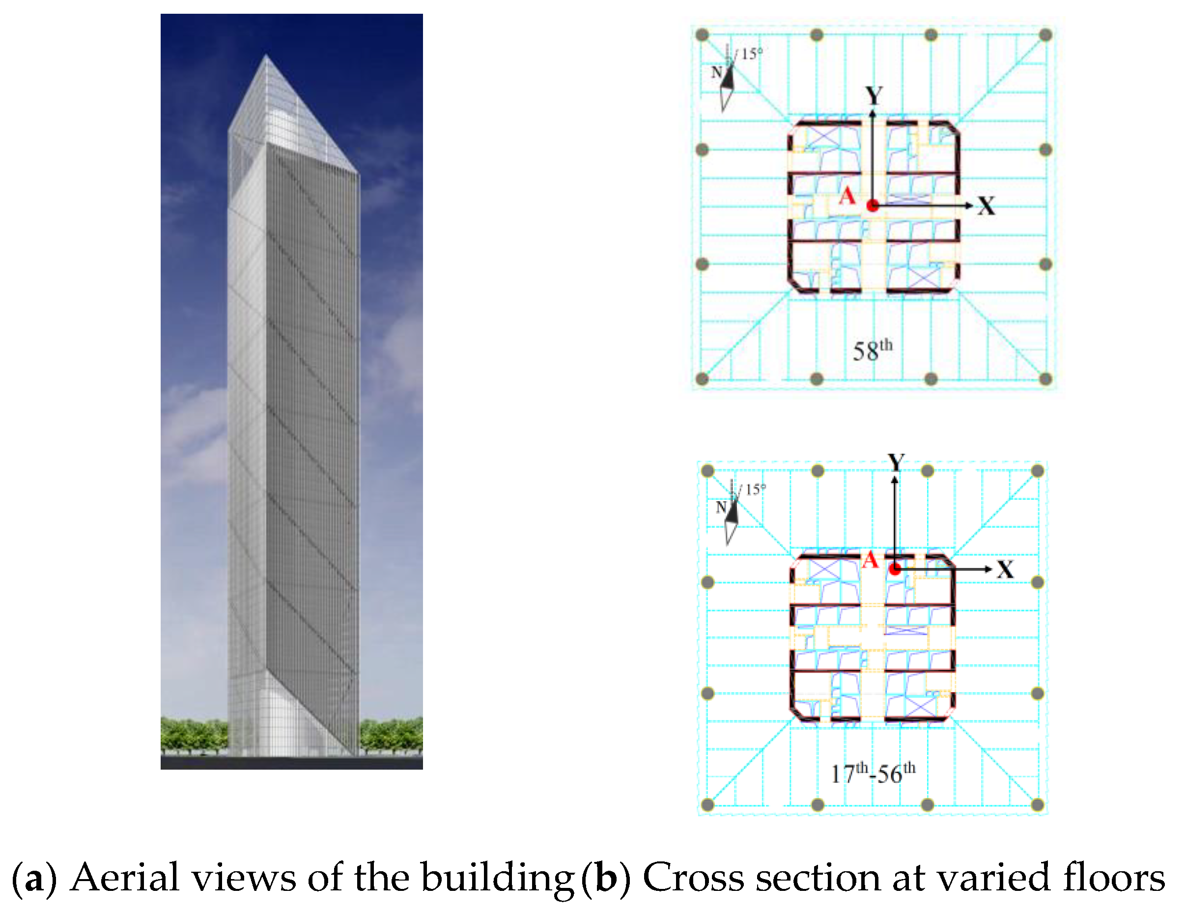
Figure 1. Overview of the Leatop Plaza.
Applsci 10 02965 g001
Figure 2. Three functional layers involved in the structural health monitoring (SHM) system.
Applsci 10 02965 g002
Figure 3. Best track of Typhoon Mangkhut and location of the study building.
Applsci 10 02965 g003
Figure 4. Flowchart of the stability diagram method.
Applsci 10 02965 g004
Figure 5. Time histories of wind measurements at two sites (the vertical gray dot line denotes time constant of 17:00 on 16 September 2018 when Mangkhut got closest to the study site).
Applsci 10 02965 g005
Figure 6. Time histories of acceleration responses at the 58th floor of Leatop Plaza.
Applsci 10 02965 g006
Figure 7. Correlation between mean wind speed measured at two sites and the standard deviation of acceleration response at 56/F of Leatop Plaza. (a) SHM; (b) Canton Tower.
Applsci 10 02965 g007
Figure 8. Comparison of measured maximum acceleration responses with those recommended by different comfort criteria.
Applsci 10 02965 g008
Figure 9. Comparison of power spectral density curves by the Welch and the Yule–Walker methods. (a) Along X; (b) Along Y.
Applsci 10 02965 g009
Figure 10. Typical random decrement (RD) signatures and estimation of natural frequency and damping ratio for first swaying mode at the 56th floor (N: sample number involved in RD signature). (a) Along X; (b) Along Y.
Applsci 10 02965 g010
Figure 11. Stability diagram overlaid by power spectral density (PSD) results at the 56th floor. (a) Along X; (b) Along Y.
Applsci 10 02965 g011
Figure 12. Correlation between the building fundamental frequencies with building height and existing prediction models.
Applsci 10 02965 g012
Figure 13. Natural frequencies and damping ratios at three periods during the passage of Mangkhut. (a) Dir-X; (b) Dir-Y.
Applsci 10 02965 g013
Figure 14. Amplitude-dependence of natural frequencies and damping ratios for the first two swaying modes and the first torsional mode along two measurement directions. (a) 1st swaying mode; (b) 1st torsional mode; (c) 2nd swaying mode.
Applsci 10 02965 g014
Figure 15. Mode shapes identified via SSI and root-mean-square (RMS) methods against code predictions for the first two swaying modes (i.e., Mode 1 and Mode 3) and the first torsional mode (Mode 2). (a) Dir-X; (b) Dir-Y.
Applsci 10 02965 g015
Figure 16. Mode shapes for the first five orders from simulation via finite element method.
Applsci 10 02965 g016
Table 1. Layout of accelerometers installed on Leatop Plaza.
Floor
No.
Height
(m)
Eccentric Distance (m) along X-Direction (East–West)Eccentric Distance (m) along Y-Direction (North–South)
58th2600.20
56th2521.79
47th2151.79
39th1751.79
31st1451.79
28th1351.79
23rd1151.79
17th801.79
Table 2. Information of meteorological stations.
Meteorological StationGeographic CoordinatesAnemometer Height (m)
Canton Tower23°6′44″ N,113°19′52′ E532
Leatop Plaza23°7′54′ N,113°19′56′ E303
Table 3. Peak factors from measurement and calculation during different periods.
Dir.Approaching PeriodNearest PeriodLeaving Period
MeasuredCalculatedMeasuredCalculatedMeasuredCalculated
X2.993.263.033.263.033.28
Y3.093.262.973.253.253.25
Table 4. Results of damping ratio and natural frequency estimated via random decrement technique (RDT) and stochastic subspace identification (SSI).
Modes1st Swaying Mode1st Torsional Mode2nd Swaying Mode
SNEWSNEWSNEW
fRDT (Hz)0.1820.1830.4290.4290.6560.683
SSI (Hz)0.1800.1830.4420.4330.6790.679
Diff (%)1.100.003.030.9303.510.590
ξRDT (%)1.021.031.030.9100.7100.900
SSI (%)0.8900.9101.190.9000.7500.890
Diff. (%)12.811.715.91.325.341.11
Note: Diff. = (RDT−SSI)/RDT.
Table 5. Values of natural frequency and damping ratio during three selected periods.
Mode1st Swaying1st Torsional2nd Swaying
DirectionY (S–N)X (E–W)Y (S–N)X (E–W)Y (S–N)X (E–W)
f (Hz)Approach0.1850.1860.4370.4370.6730.699
Nearest0.1810.1830.4290.4290.6560.683
Leaving0.1820.1860.4330.4330.6630.689
ξ (%)Approach0.4900.4500.4100.3400.4700.710
Nearest0.8400.9001.030.9100.7100.890
Leaving0.6200.5300.4800.4900.6100.720
Table 6. Results of natural frequencies of Leatop Plaza.
Mode No.Measurement (Hz)Simulation (Hz)Difference (%)Mode Type
10.1830.16410.41st mode in X direction (sway)
20.1820.1678.241st mode in Y direction (sway)
30.4290.3889.561st mode in Z direction (torsion)
40.6830.59213.32nd mode in X direction (sway)
50.6560.6126.712nd mode in Y direction (sway)
Table 7. Values of modal assurance criterion (MAC) and normalized modal difference (NMD) between measured and simulated mode shapes.
1st Swaying1st Torsion2nd Swaying
DirectionXYX(Y)XY
MAC (%)99.299.797.588.277.5
NMD (%)9.35.216.036.553.9