1. Introduction
Pulmonary Embolism (PE) is a deadly disease formed when emboli lodge in the pulmonary arteries. Emboli can be formed in-situ or as a result of deep venous thrombosis, traveling through the blood stream, and traversing the right heart cavities. Emboli lodged in the pulmonary arteries impede blood flow, causing poor or no oxygen exchange and increasing right ventricular afterload. Decreased oxygenation can result in poor oxygen delivery to vital organs that can cease to function or malfunction. An increased right ventricular afterload results in right heart strain, which can cause right-sided heart failure, ischemia, and death. Lack or delay in treatment increases morbidity and mortality [
1]. From an epidemiological standpoint, in the United States, PE affects 300,000–600,000 Americans/year, resulting in 12,000–80,000 deaths [
2]. There are no global numbers for Europe, but the incidence of PE in Sweden, for example, is estimated to be 19,000 cases per year and 39,480 France [
3].
Pulmonary embolism is clinically presented with a non-specific symptomatology that includes chest pain, shortness of breath and tachycardia, and may include hemoptysis, hypotension, and loss of consciousness. The clinical diagnosis of PE can be challenging, with radiological Computed Tomography Pulmonary Angiography (CTPA) being the gold standard. This procedure involves injecting a contrast agent into the patient’s pulmonary arteries, imaging with a computed tomography (CT) scanner and reading the images to find filling defects. Such filling defects are the result of the emboli blockage of the contrast agent. Since the clinical symptoms for PE are non-specific and there is no laboratory test for the diagnosis of PE, many of the CTPA performed in clinical settings are not positive for PE.
Computer Aided Detection (CAD) methods have been used in PE diagnosis to measure the right ventricle strain [
4,
5] and to detect PE automatically. In comparison with a panel of expert radiologists, the sensitivity of an individual radiologist ranges from 77% to
[
6,
7]. Works on using CAD systems as a second reader have shown increases in reader sensitivity of 92–98% [
6,
7,
8,
9,
10,
11,
12,
13]. However, current systems of CAD for PE show moderate sensitivity (
) at a fairly high false positive rate (three false positives per study), preventing their general adoption in clinical practice [
14].
CAD algorithms for PE follow a two-step process, in which a set of candidate points are selected and tested to discriminate between emboli and false detections. Older studies extracted hand-crafted features around candidate points and used classification techniques to evaluate them [
9,
12]. Modern methods take advantage of convolutional neural networks for both feature extraction and classification by generating planar reformatted images centered around candidate points [
15,
16]. The more recent work [
17] also includes context information around the candidate point to improve detection performance.
In this work, we hypothesize that deep convolutional neural networks can be used to directly detect emboli from images, without the need to detect candidate points. By using the whole image to detect emboli, we let the network use both local and global image characteristics to discern between PE and other image structures.
2. Materials and Methods
We treated the problem of CAD for PE as a segmentation problem, where we directly inputted the image and outputted a segmentation mask of the emboli. We post-processed emboli segmentations to generate emboli detections and evaluated the performance of the method, following the methodology of González et al. [
14].
2.1. Dataset
We used a total of 80 Computed Tomography Pulmonary Angiograms (CTPA) from the CAD-PE challenge [
14,
18,
19]. While the dataset was not obtained for this work, we describe it here for the sake of clarity. The original scans were supplied from six different hospitals and coordinated by the “
Central Diagnostic Radiology Unit” in Madrid (Spain). SIEMENS Somaton Sensation 40 scanners were used for the data acquisition with a pixel size between 0.58 and 0.85 mm and a slice thickness oscillating between 0.75 and 1.5 mm.
Each scan was analyzed independently for the presence of PE by three radiologists with more than 15 years of experience establishing the reference standard. In the case of discrepancy, a majority voting scheme was employed. Furthermore, each radiologist marked regions of interest (ROI) around all the visible clots using the sagittal and coronal views. The regions of interest were segmented by applying an intensity threshold, binary closing operations and connected component analysis. Each of the individual connected components represented a different embolus clot, the
Figure 1 shows an example of these findings. There was a total of 167 emboli in 60 training cases, with a per-case total average volume of 5.04 ×
voxels. The number of emboli per scan ranged between 0 and 21. A variation in the reference standard was performed by dilating the border of each embolus with an epsilon value as tolerance margin (
= 2 mm and
= 5 mm). This modification affected the number of emboli and their size in the reference segmentations, but was only used for test purposes, leaving the original reference standard (
= 0 mm) to train and validate the system.
2.2. Network Architectures
2.2.1. Network
The
network was based on the U-Net structure [
20]. The input to the network consisted of axial slices of the training data, and the output was emboli segmentation. We used the reference standard segmentations with
= 0 mm tolerance level as ground truth. The U-Net was composed of four convolution and polling levels in the down-sampling encoder. Each level was composed of the
convolution operations that doubled the number of filters with respect to the previous level. The first level started with 32 filters and the last encoder block had 256. Each encoder level was followed by a
Max-Pooling operation. At the end of the encoder, we performed two further
convolutions with 512 filters each. The decoding was performed by four up-sampling blocks consisting of an up-sampling operation, followed by the concatenation with the output of the corresponding encoder level data and two
convolution operations, with the same number of filters as its equivalent encoder level. To finish, a last
convolution was performed to obtain the network output. All of the convolution outputs were activated with a “ReLU” function except the last
convolution, which used a sigmoid activation to concentrate the output values in the extremes of the range [0, 1]. In addition, batch normalization was used for the convolution activations, to maintain the mean close to zero and its standard deviation close to one.
2.2.2. Network
This method was a variation of the network where, instead of using a single axial slice as input, we used a composition of five slices, corresponding to the two above and the two below the target slice we wished to segment. We still used a single slice reference standard segmentation, comparing this with the network output as minimization objective.
2.2.3. Network
The method consisted of a three-axis version, where we used the exact same structure as the network but trained it with slices in the three axial direction (transverse, coronal, and sagittal planes). Since the scans did not have the same z resolution, we resampled them to achieve a homogeneous size of . At the prediction stage, we tested each scan three times, with input slices coming from different planes, obtaining three predictions, which were then merged using the maximum value on each pixel.
2.3. Training
To train the three different networks, we split the 60 scans into two groups: 55 scans for training and 5 for validation. As pre-processing, the data were clipped in the range [−200, 500] Hounsfield Units (HU) and normalized to the range [0, 1]. Each model was trained for 200 epochs, keeping the models with the best validation performance, which were then used to obtain the final coordinates over the test subset. As objective loss function, all methods minimized the binary cross-entropy between reference standard segmentations and the predicted ones. We used the Adam optimizer with a learning rate of 0.0005.
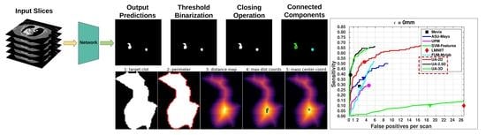
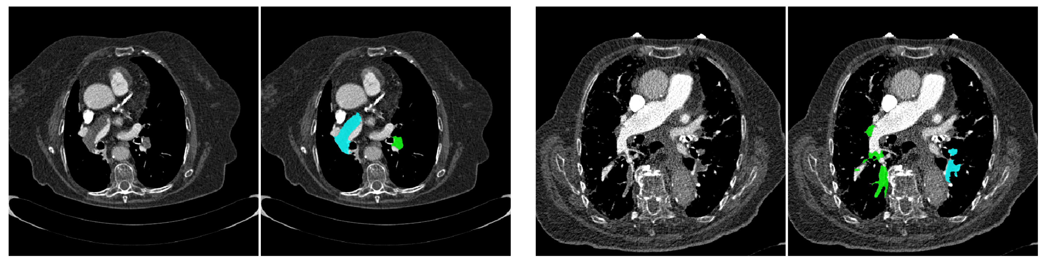
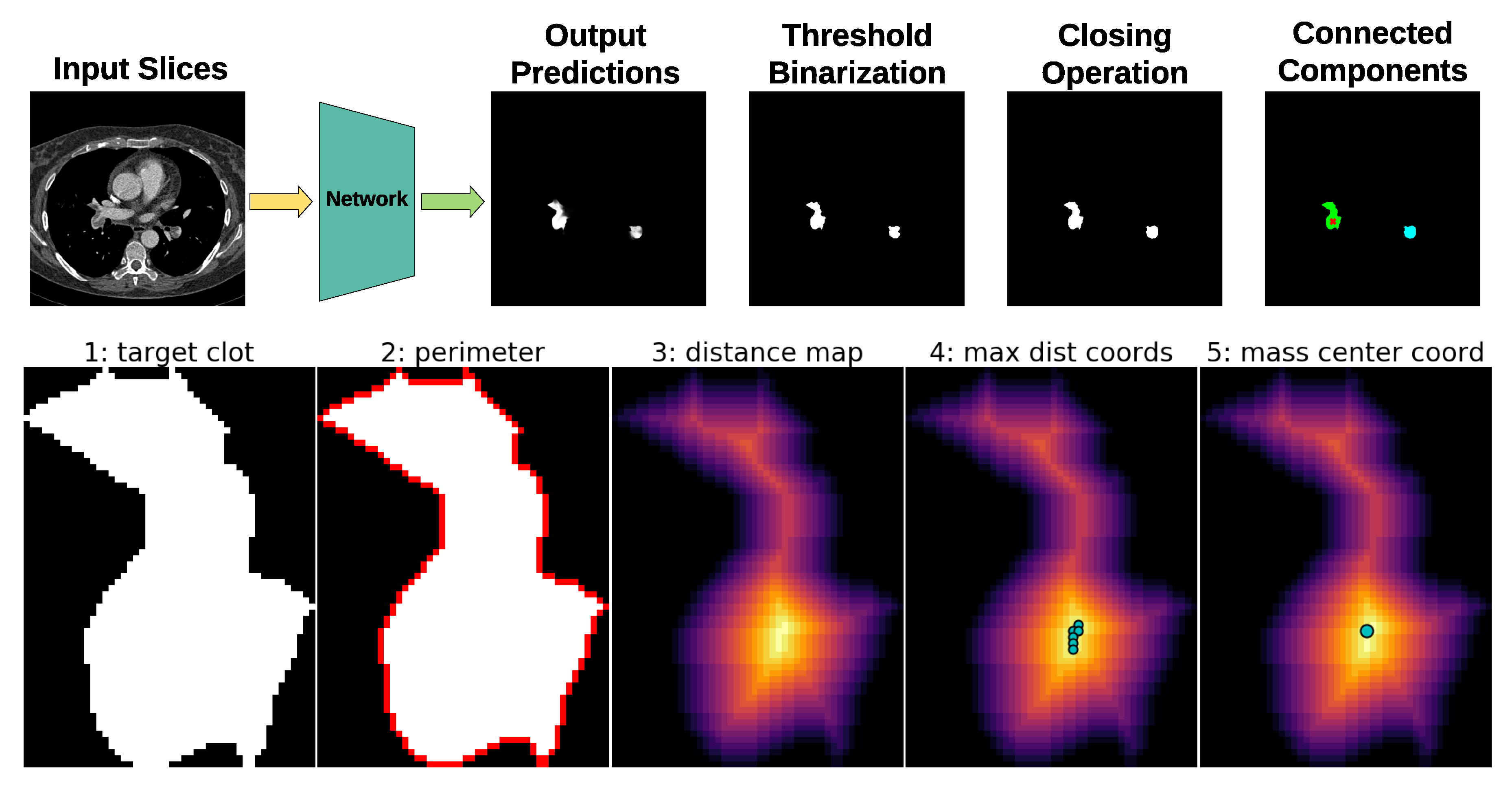
2.4. Post-Processing
After the training process, the model with the best validation performance was used to obtain the probabilistic segmentations on the test subset. These results were then transformed into emboli coordinates using the method shown in
Figure 2. First, from the network predictions, a threshold of 0.5 was used to obtain a binarized mask. A binary closing operation with a kernel size of
was used to eliminate small noise on the mask. Then, connected components analysis was used to generate the different individual emboli.
In a second stage, the coordinates of each individual embolus were extracted. We applied an inner distance transform for each connected component, and found the pixels that were furthest from the perimeter. Then, we obtained the closest coordinates of such pixels to the center of mass of the embolus. We applied this method to all connected components, generating a per-detected embolus list of coordinates. Finally, each coordinate was associated with a score representing its probability of being a clot. This score was the network output value at the coordinate position generating a list of values composed by the coordinate in the “x”, “y”, and “z” axes and the “score” of probability.
2.5. Evaluation Metric
To compare the performance of the three different methods, we used the Free-response Receiver Operating Characteristic (FROC) curve. This tool uses sensitivity in the detection of emboli, defined as the total number of findings divided by the total number of emboli, together with the average false positive per scan obtained by adding the false positive detections divided by the total number of test scans. An embolus was correctly detected if any coordinate obtained by the tested network fell inside its reference standard segmentation. FROC analysis is standard for the evaluation of methods that locate several lesions in images, but unfortunately no clear figure of merit is widely accepted for such curves [
21], and we resort to visual inspection of the curves for the comparison of the methods.
3. Results
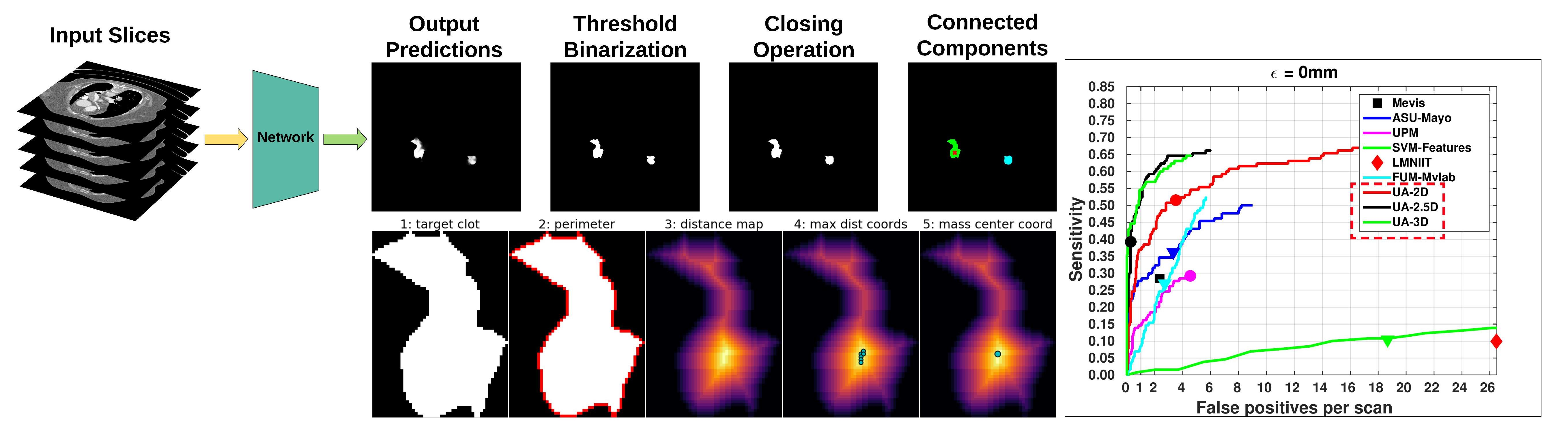
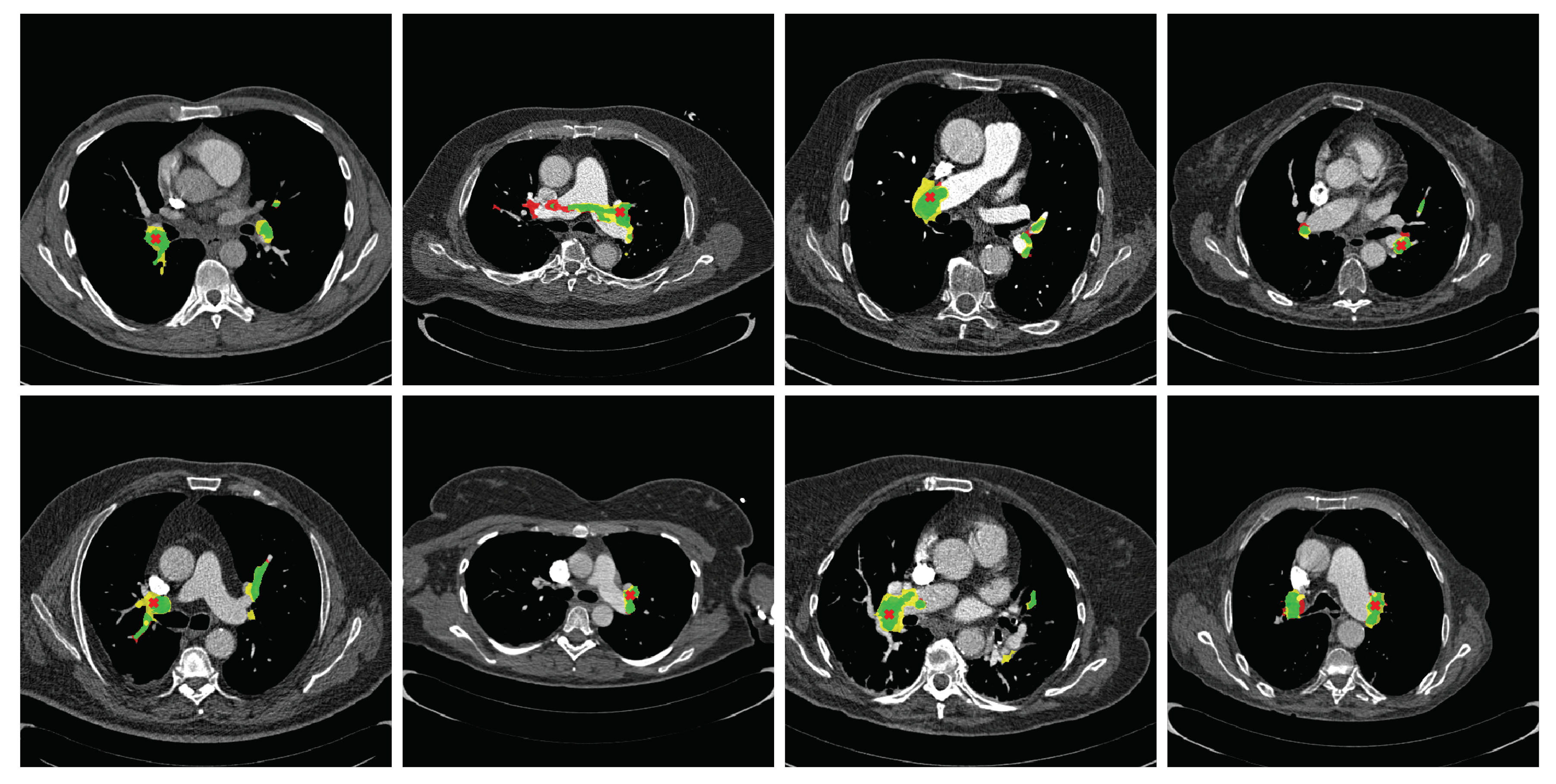
First, we evaluated the segmentation performance of the proposed method. Qualitative segmentation results are shown in
Figure 3, where green labels represent true positives, red labels false negatives, and yellow labels false positives. The average per-scan segmentation Dice score was 0.485 (standard deviation of 0.297) for the
network, 0.367 (standard deviation of 0.214) for the
network, and 0.296 (standard deviation of 0.160) for the
network. In all the cases, the standard deviation showed large discrepancies across scans.
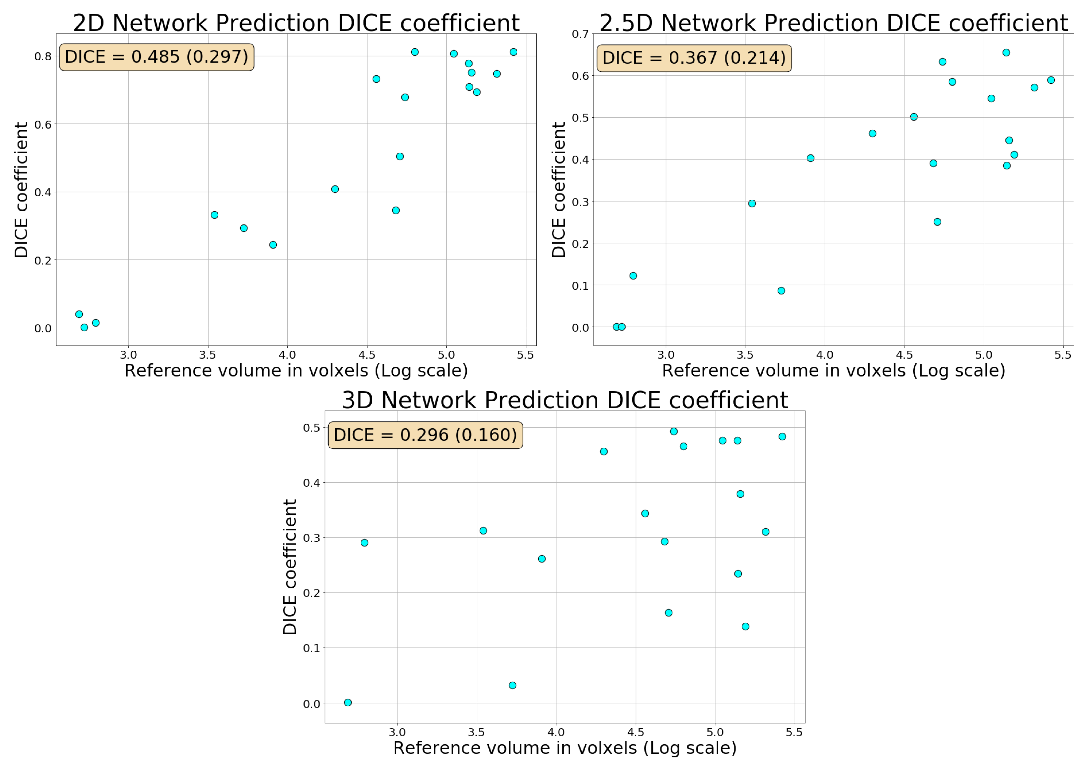
Figure A1 shows the relationships between the total size of the emboli in the scan, measured in voxels, and the Dice coefficient. There was a clear trend where the larger was the emboli in the scan, the better was the segmentation.
Table 1 shows the per embolus sensitivity of each of the three methods and the number of false positives per scan for the three tolerance margins
= 0 mm,
= 2 mm, and
= 5 mm. The threshold to set the operating point of the method was set at
. There was a clear improvement of the
method over the
method. For
= 0 mm and
= 2 mm, the sensitivity was similar, but the number of False Positives per Scan (FPS) was more than halved. For
= 5 mm, there was an increase in sensitivity paired with a decrease in the number of FPS. The data in the table show no clear improvement between the
and
methods. The
method had higher sensitivity, but also a higher number of FPS.
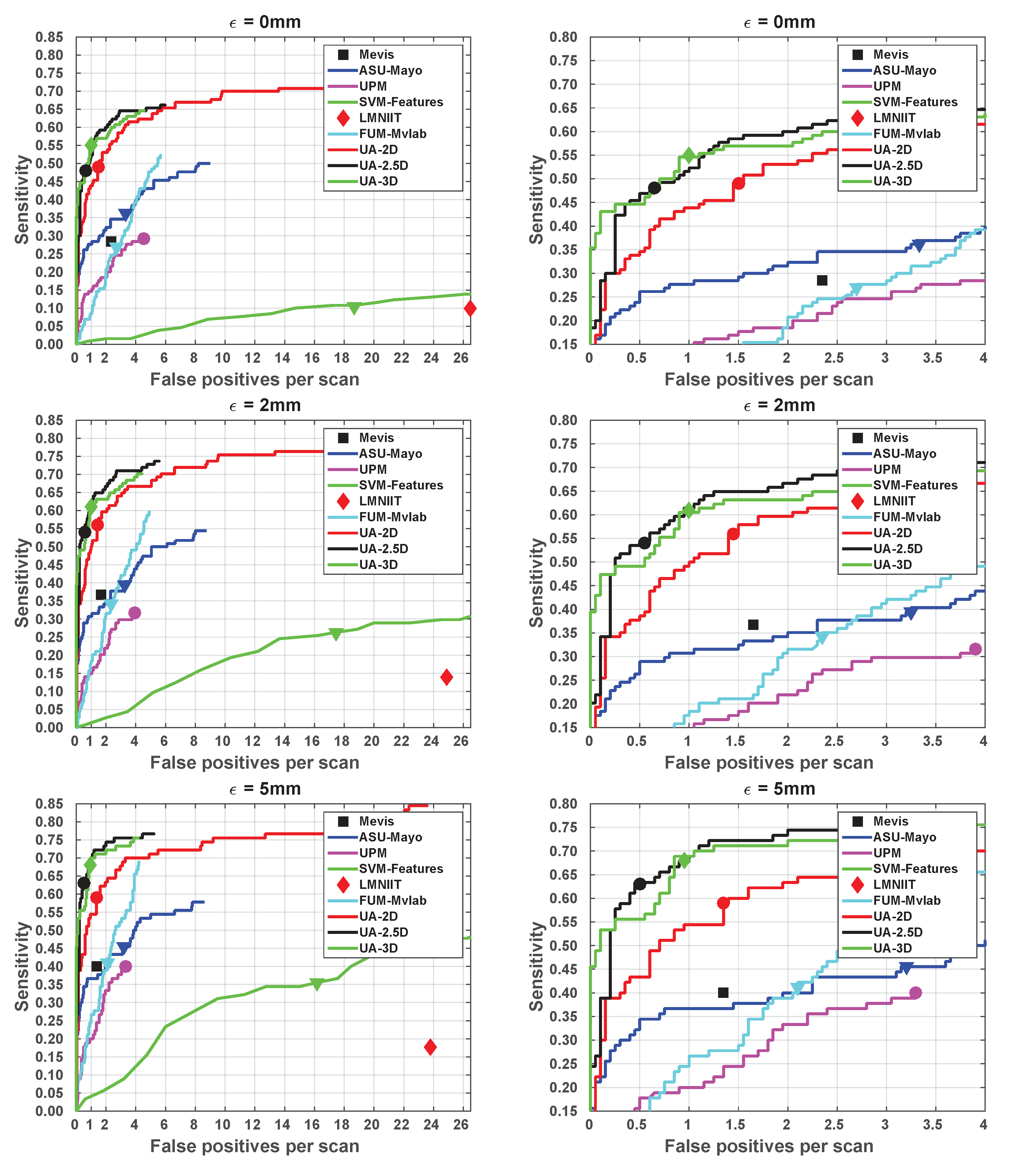
Figure 4 displays the FROC curves. We included the results of the CAD-PE challenge in these images challenge to enable comparison [
14,
18]. We refer the reader to these references for a description and thorough evaluation of the other methods. The
ASU-Mayo method is best described in [
15] and the
FUM-Mvlab method in [
22]. The x-axis scale changes between the left and the right columns. Please note that most methods do not detect all emboli, since they are not part of their candidate selection mechanism or the segmentations did not reach the
threshold. The three proposed methods outperformed the other participants of the CAD-PE challenge for all the regimes of FPS. The
and
methods outperformed the
method for all the regimes of FPS in which they have data. There was a small increase in sensitivity of the
method over the
method in the range [0.25–4] FPS. The
method clearly outperformed the
method on the range [0–0.25] FPS.
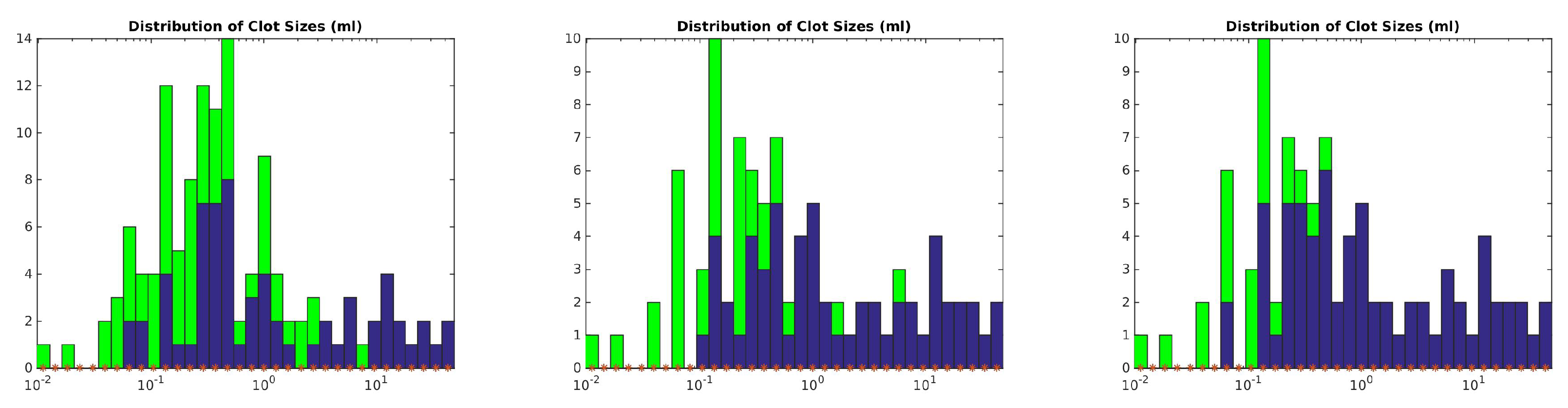
The performance of the three proposed methods with respect to embolus volume is shown in
Figure 5. Each sub-image displays the histogram of embolus volume in green and the amount of emboli detected in blue. The x-axis is in logarithmic scale. All methods had problems finding emboli with less than
mL volume. For emboli above
mL volume, the more complex is the network, the better it performed, with the
network being the best-performing method. The cutoff value used to generate these histograms was the same as that used for
Table 1.
The network processed one case in s. The network in s. The method was faster than the method because it produced a lower amount of connected components, and therefore the post processing was faster ( took s vs. took s). The method processed one case in s, with post processing time of s. All methods were fast enough to be used in an emergency setting. Timing was measured in an Intel i7-6850k CPU with an Nvidia 1080-Ti graphics card.
4. Discussion
CAD methods for pulmonary embolism have long suffered from a moderate sensitivity at high regimes of false positives per scan, hindering their clinical use. Recent neural network methods have improved the results of CAD for PE, using the same classic machine learning methodology consisting of finding candidate points and then evaluating whether each candidate belongs to an embolus. We present a method that avoids the use of candidate points by treating CAD for PE as a segmentation problem, turning the segmentation into detection points as a post-processing step. We evaluated three methods with this underlying idea: a method using axial slices as input data, a method using a slab of the CT scan, and a method that combines information from axial, sagittal, and coronal planes.
The three methods presented outperformed the other participants on the CAD-PE challenge. This may be because there was information about the location of the embolus that was relevant to its shape and image characteristics. A distal embolus might not look similar if it is in the upper lobes or the lower lung lobes. By using global segmentation strategies, the network can learn such differences. When compared with the work of Lin et al. [
17], the proposed methods showed lower performance at the regime of two false positives per scan. It should be noted that the performance of their method at lower FPS regimes, which are required for clinical practice, was unclear.
The methods improved when more data were added as input to the network. As such, the network outperformed the network on all regimes of FPS. This is logical. Emboli are structures, and image variations on the z-axis contain valuable information. The authors were surprised to see that the method did not clearly outperform the method on all FPS regimes. However, there was a clear improvement in performance at very low FPS regimes ([0–0.25]), which indicates that the method successfully increases the score of certain emboli. This effect makes sense, since some emboli that might not be clear in axial slices may be very clear in coronal or sagittal slices, and the context on such planes might be more relevant than the few slices that the method uses. Surprisingly, the performance in terms of segmentation decreased with complexity, with the method achieving a better Dice coefficient than the or method. This might indicate that the network is more restrictive in its findings, producing fewer false positives while keeping the embolus located.
There are several limitations to this study. First, we used only 60 CT scans for training. While they account for more than 7000 slices, this number is small for training modern neural networks and could be considered a small dataset. A larger number of scans would likely improve the performance of the network. A thorough study on the improvement of performance with respect to the number of training scans might shed more light on the optimal number of scans required for training. Second, the scans on which we trained the dataset and the scans on which we tested them come from the same institution and had been obtained with the same acquisition machines, which might bias the results positively. The evaluation on external datasets, such as the one in [
22], was left for future work. Third, there is room to improve the segmentation performance of the network, since the baseline network structure is very simple. More complex networks, using squeeze and excite blocks, for instance, may greatly improve segmentation results that could lead to better emboli detection. Fourth, the proposed method, as all other CAD for PE methods referenced in this paper, only detects emboli, and it is not capable of classifying them as obstructive or non-obstructive. Such clinical information is important, but impossible to obtain with the current dataset, since we do not have these labels for the emboli, nor do we have a method to segment the pulmonary artery and test for obstruction. Fifth, it would be of further interest to improve the method to compute clot burden scores, such as those in [
23,
24]. However, such scores require information on the anatomical location of the embolus, which is not available with the method in the present study.
We do not know whether the proposed network would have an impact on clinical practice. Other methods have been evaluated by radiologists and the sensitivity of radiologists, especially those without extensive experience, has been shown to improve without reducing specificity. The proposed method outperforms other CAD for PE algorithms and would likely have the same effect on radiologist’s performance while being easier to use due to its lower rate of false positives per scan.
5. Conclusions
This article shows that the standard paradigm for CAD for PE algorithms of finding candidate points and then evaluating their belonging to an embolus is inferior to the proposed paradigm of directly locating emboli by treating the problem as a segmentation method. We achieved state-of-the art performance with this paradigm using a simple segmentation network as backbone.
Author Contributions
Conceptualization, G.G. and C.C.-E.; methodology, G.G. and C.C.-E.; software, C.C.-E. and G.G.; validation, G.G., M.C., and C.C.-E.; formal analysis, G.G.; investigation, C.C.-E. and G.G.; resources, G.G.; writing—original draft preparation, C.C.-E. and G.G.; writin-g–review and editing, G.G., M.C., and C.C.-E.; visualization, C.C.-E. and G.G.; data curation, G.G.; supervision, G.G. and M.G.; project administration, G.G.; and funding acquisition, M.C. All authors have read and agreed to the published version of the manuscript.
Funding
This research received no external funding.
Acknowledgments
We gratefully acknowledge the support of NVIDIA Corporation with the donation of the GPU used for this research.
Conflicts of Interest
G.G. is the owner of Sierra Research S.L.U., a company specialized in medical image processing. The authors declare no other conflicts of interest.
Abbreviations
The following abbreviations are used in this manuscript:
| CAD | Computer Aided Detection |
| CAD-PE | Computer Aided Detection of Pulmonary Embolism |
| CTPA | Computed Tomography Pulmonary Angiography |
| FPS | False positives per scan |
| FROC | Free-Response Receiver Operating Characteristic |
| HU | Hounsfield Units |
| PE | Pulmonary Embolism |
Appendix A
The Dice coefficient measures the similarity between the reference and the predicted embolus masks. The results represented in this appendix show the high correlation between the embolus size and its correct segmentation predicted by the networks.
Figure A1.
Comparison plot between per scan Dice coefficient and the total reference emboli volume in logarithmic scale using , , and network versions.
Figure A1.
Comparison plot between per scan Dice coefficient and the total reference emboli volume in logarithmic scale using , , and network versions.
References
- Smith, S.B.; Geske, J.B.; Maguire, J.M.; Zane, N.A.; Carter, R.E.; Morgenthaler, T.I. Early anticoagulation is associated with reduced mortality for acute pulmonary embolism. Chest 2010, 137, 1382–1390. [Google Scholar] [CrossRef] [PubMed]
- Rathbun, S. The surgeon general’s call to action to prevent deep vein thrombosis and pulmonary embolism. Circulation 2009, 119, e480–e482. [Google Scholar] [CrossRef] [PubMed]
- Konstantinides, S.V.; Meyer, G.; Becattini, C.; Bueno, H.; Geersing, G.J.; Harjola, V.P.; Huisman, M.V.; Humbert, M.; Jennings, C.S.; Jiménez, D.; et al. 2019 ESC Guidelines for the diagnosis and management of acute pulmonary embolism developed in collaboration with the European Respiratory Society (ERS): The Task Force for the diagnosis and management of acute pulmonary embolism of the European Society of Cardiology (ESC). Eur. Heart J. 2019, 41, 543–603. [Google Scholar] [CrossRef]
- González, G.; Jiménez-Carretero, D.; Rodríguez-López, S.; Kumamaru, K.; George, E.; Estépar, R.; Rybicki, F.; Ledesma-Carbayo, M. Automated axial right ventricle to left ventricle diameter ratio computation in computed tomography pulmonary angiography. PLoS ONE 2015, 10. [Google Scholar] [CrossRef] [PubMed]
- Kumamaru, K.; George, E.; Aghayev, A.; Saboo, S.; Khandelwal, A.; Rodríguez-López, S.; Cai, T.; Jiménez-Carretero, D.; Estépar, R.; Ledesma-Carbayo, M.; et al. Implementation and performance of automated software for computing right-to-left ventricular diameter ratio from computed tomography pulmonary angiography images. J. Comput. Assist. Tomogr. 2016, 40, 387–392. [Google Scholar] [CrossRef] [PubMed][Green Version]
- Das, M.; Mühlenbruch, G.; Helm, A.; Bakai, A.; Salganicoff, M.; Stanzel, S.; Liang, J.; Wolf, M.; Günther, R.W.; Wildberger, J.E. Computer-aided detection of pulmonary embolism: Influence on radiologists’ detection performance with respect to vessel segments. Eur. Radiol. 2008, 18, 1350–1355. [Google Scholar] [CrossRef] [PubMed]
- Wittenberg, R.; Berger, F.H.; Peters, J.F.; Weber, M.; van Hoorn, F.; Beenen, L.F.; van Doorn, M.M.; van Schuppen, J.; Zijlstra, I.A.; Prokop, M.; et al. Acute pulmonary embolism: Effect of a computer-assisted detection prototype on diagnosis—An observer study. Radiology 2012, 262, 305–313. [Google Scholar] [CrossRef] [PubMed]
- Bi, J.; Liang, J. Multiple instance learning of pulmonary embolism detection with geodesic distance along vascular structure. In Proceedings of the 2007 IEEE Conference on Computer Vision and Pattern Recognition, Minneapolis, MN, USA, 17–22 June 2007; pp. 1–8. [Google Scholar]
- Liang, J.; Bi, J. Local characteristic features for computer-aided detection of pulmonary embolism in CT angiography. In Proceedings of the First MICCAI Workshop on Pulmonary Image Analysis, New York, NY, USA, 6–10 September 2008; pp. 263–272. [Google Scholar]
- Dundar, M.M.; Fung, G.; Krishnapuram, B.; Rao, R.B. Multiple-instance learning algorithms for computer-aided detection. IEEE Tran. Biomed. Eng. 2008, 55, 1015–1021. [Google Scholar] [CrossRef] [PubMed]
- Zhou, C.; Chan, H.P.; Sahiner, B.; Hadjiiski, L.M.; Chughtai, A.; Patel, S.; Wei, J.; Cascade, P.N.; Kazerooni, E.A. Computer-aided detection of pulmonary embolism in computed tomographic pulmonary angiography (CTPA): Performance evaluation with independent data sets. Med. Phys. 2009, 36, 3385–3396. [Google Scholar] [CrossRef] [PubMed]
- Bouma, H.; Sonnemans, J.J.; Vilanova, A.; Gerritsen, F.A. Automatic detection of pulmonary embolism in CTA images. IEEE Trans. Med. Imaging 2009, 28, 1223–1230. [Google Scholar] [CrossRef] [PubMed]
- Park, S.C.; Chapman, B.E.; Zheng, B. A multistage approach to improve performance of computer-aided detection of pulmonary embolisms depicted on CT images: Preliminary investigation. IEEE Trans. Biomed. Eng. 2010, 58, 1519–1527. [Google Scholar] [CrossRef] [PubMed]
- González, G.; Jimenez-Carretero, D.; Rodríguez-López, S.; Cano-Espinosa, C.; Cazorla, M.; Agarwal, T.; Agarwal, V.; Tajbakhsh, N.; Gotway, M.B.; Liang, J.; et al. Computer Aided Detection for Pulmonary Embolism Challenge (CAD-PE). Available online: https://arxiv.org/abs/2003.13440 (accessed on 30 March 2020).
- Tajbakhsh, N.; Shin, J.Y.; Gotway, M.B.; Liang, J. Computer-aided detection and visualization of pulmonary embolism using a novel, compact, and discriminative image representation. Med. Image Anal. 2019, 58, 101541. [Google Scholar] [CrossRef] [PubMed]
- Tajbakhsh, N.; Gotway, M.B.; Liang, J. Computer-Aided PulmonaryEmbolism Detection Using aNovel Vessel-Aligned Multi-planar Image Representation and Convolutional Neural Networks Nima. In International Conference on Medical Image Computing and Computer-Assisted Intervention; Springer: Cham, Switzerland, 2015; Volume 9350, pp. 62–69. [Google Scholar] [CrossRef]
- Lin, Y.; Su, J.; Wang, X.; Li, X.; Liu, J.; Cheng, K.T.; Yang, X. Automated Pulmonary Embolism Detection from CTPA Images Using an End-to-End Convolutional Neural Network. In Proceedings of the Medical Image Computing and Computer Assisted Intervention—MICCAI 2019, Shenzhen, China, 13–17 October 2019; Shen, D., Liu, T., Peters, T.M., Staib, L.H., Essert, C., Zhou, S., Yap, P., Khan, A., Eds.; Springer: Cham, Switzerland, 2019; Volume 11767, pp. 280–288. [Google Scholar] [CrossRef]
- Gonzalez, G. CAD-PE Challenge Website. Available online: http://www.cad-pe.org (accessed on 16 April 2020).
- Gonzalez, G. CAD-PE Dataset. Available online: http://dx.doi.org/10.21227/9bw7-6823 (accessed on 16 April 2020).
- Ronneberger, O.; Fischer, P.; Brox, T. U-net: Convolutional networks for biomedical image segmentation. In International Conference on Medical Image Computing and Computer-Assisted Intervention; Springer: Cham, Switzerland, 2015; pp. 234–241. [Google Scholar]
- Moskowitz, C.S. Using free-response receiver operating characteristic curves to assess the accuracy of machine diagnosis of cancer. JAMA 2017, 318, 2250–2251. [Google Scholar] [CrossRef] [PubMed]
- Masoudi, M.; Pourreza, H.R.; Saadatmand-Tarzjan, M.; Eftekhari, N.; Zargar, F.S.; Rad, M.P. Data descriptor: A new dataset of computed-tomography angiography images for computer-aided detection of pulmonary embolism. Sci. Data 2018, 5, 1–9. [Google Scholar] [CrossRef] [PubMed]
- Miller, G.A.; Sutton, G.C.; Kerr, I.H.; Gibson, R.V.; Honey, M. Comparison of Streptokinase and Heparin in Treatment of Isolated Acute Massive Pulmonary Embolism. Br. Med. J. 1971, 2, 681–684. [Google Scholar] [CrossRef] [PubMed]
- Qanadli, S.D.; El Hajjam, M.; Vieillard-Baron, A.; Joseph, T.; Mesurolle, B.; Oliva, V.L.; Barré, O.; Bruckert, F.; Dubourg, O.; Lacombe, P. New CT index to quantify arterial obstruction in pulmonary embolism: Comparison with angiographic index and echocardiography. Am. J. Roentgenol. 2001, 176, 1415–1420. [Google Scholar] [CrossRef] [PubMed]
© 2020 by the authors. Licensee MDPI, Basel, Switzerland. This article is an open access article distributed under the terms and conditions of the Creative Commons Attribution (CC BY) license (http://creativecommons.org/licenses/by/4.0/).


