1. Introduction
Concrete is strong in compression and weak in tension. In prestressed concrete girders, compressive force is applied in the tension area to compensate for the disadvantages of concrete. This prestressing force is induced in a girder during its construction, which helps reduce the tensile stress generated during service. Prestressing is divided into two types: post-tension and pre-tension.
In the pre-tensioning method tendons are tensioned before concrete is poured and the tension is retained until completing hardening of the concrete. Thereafter, the tendons are gradually released to introduce prestress into the concrete. In the post-tension method, prestress is introduced by tensioning tendons and fixing one of their ends to a concrete girder after the concrete hardens. In this method, the tendons and the concrete should not be attached at the time of tensioning the tendons, which means that the duct for arranging the tendon should be installed in advance. After the introduction of tension, grouting should be performed with cementitious grout to prevent corrosion of the tendons and to ensure that the tendons adhere to the concrete. After the tendons are grouted this way, re-tensioning is impossible. To overcome these disadvantages of conventional prestressing, many researchers are exploring prestressing techniques that employ shape memory alloys (SMAs).
SMAs have several unique properties. The two most important properties are the shape memory effect (SME) and superelasticity. SME refers to the phenomenon that if an SMA is deformed, it regains its former shape upon heating [
1,
2,
3]. Superelasticity refers to the phenomenon of an SMA undergoing a large amount of inelastic deformation and recovering its shape after unloading automatically without heating [
4,
5]. The SME of an SMA strip/bar can be used to prestress concrete. For example, in principle, if a straight SMA bar is deformed by pulling and then heated above a certain temperature, it will shrink to its original length. However, if the deformation recovery is restrained by embedding the SMA in concrete structures, a mechanical stress is induced in the SMA when it is heated and cooled subsequently. This stress is called “recovery stress,” and it can be used to introduce prestressing forces in concrete structures to improve their serviceability. One of the advantages of such a prestressing technique compared to conventional prestressing is the lack of frictional losses due to the development of uniform bond stress along the length of the embedded SMA tendon. In comparison to the conventional prestressing techniques, SMA tendons can be used for prestressing thin concrete members without having to use anchor heads, oil hydraulic cylinders, ducts, or grout injection [
6].
Maji and Negret [
7] studied a smart prestressing method using SMA wires. The method uses the SME of prestrained SMA wires. Therefore, it does not require tensioning of the wires by using a hydraulic jack. Prestressing techniques that employ SMA wires or strands are relatively simple compared to mechanical prestressing, and they can be used to introduce prestressing force whenever necessary. Krstulovic-Opara and Naamann [
8] used SMA wires in cement composites to demonstrate their self-stressing capacity and compared SMA prestressing with mechanical and chemical prestressing. Soroushian et al. [
9] showed that externally installed SMA bars closed cracks in concrete structures because of the post-tensioning force generated by the SME. However, this method is associated with the problem of drilling holes and anchorage on concrete members. Li et al. [
10] and Lee et al. [
11,
12] showed the crack-closing capacity of SMA wires in concrete beams by using the closing force generated because of the recovery stress of SMA wires. There are many more studies related to crack closure by using SMA wires [
13,
14,
15,
16,
17,
18]. Moreover, there are several types of SMA wires. Most researchers have used NiTi SMA, which is considerably more expensive than steel. Czaderski et al. [
19] developed band strips with ribs by using an Fe-based SMA for prestressing concrete. Fe-based SMAs are relatively cheap and have higher strength and elastic modulus than NiTi SMAs. Cladera et al. [
20] and Lee et al. [
21] studied the applications of Fe-based SMAs. The highly developed SME, high stiffness, high strength, and low production cost of Fe-SMAs have prompted international research on their application in such civil engineering fields as damping, active control, and pre- or post-stressing tensioning of structures [
22,
23]. Shahverdi et al. [
6] proposed near-surface mounted (NSM) strengthening techniques that significantly reduce the probability of harm resulting from the corrosion of prestressing members. They aimed to estimate the applicability of Fe-SMA to NSM strengthening techniques. Zheng and Dawood [
24] analyzed fatigue crack growth in steel elements reinforced with SMA and fiber-reinforced polymer composite patches. Gholampour and Ozbakkaloglu [
25] studied the compressive behavior of high-strength concrete columns confined by SMA spirals. Moreover, an attempt has been made to enhance the compressive behavior of concrete by using a SMA [
26]. The pullout resistance of SMAs have been evaluated to compare the difference of the pullout resistance caused by SME and wire shape [
27,
28].
In this study, we conceptualize a prestressing method that considers hybrid SMA wires. This concept facilitates multi-step application of prestressing force to reinforced concrete (RC) members. “Hybrid” means that two types of SMA wires are mechanically combined. If an SMA tendon has two different austenite temperatures, its SME can be controlled in steps, which helps optimize the prestressing operation. As a preliminary study, experiments are conducted in two stages to observe the multi-step behavior of the RC member after it is prestressed using hybrid SMA wires. The first set of experiments involves multi-step shape recovery tests to evaluate the ranges of austenite temperatures of the SMA wires and to confirm the multi-step shape recovery behavior of the hybrid SMA wires. The second stage involves multi-step prestressing tests to confirm whether shape recovery is feasible under multi-step prestressing. The experimental parameters are determined by combinations of the SMA wires and heating temperatures.
2. Prestressing with Hybrid SMA Wires
For applying prestress with hybrid SMA wires, we used two different types of prestrained SMA wires as prestressing members instead of conventional tendons. The prestrained hybrid SMA wires were used to apply prestressing force rather than direct tensioning by using hydraulic jacks. When subjected to temporary heating, the prestrained hybrid SMA wires undergo recovery, and the recovery stress in the hybrid SMA wires is converted into a prestressing force as the temperature reaches the austenite temperature of one of the several materials constituting the hybrid SMA wires. In particular, heating is performed by dividing the hybrid SMA wire into multiple sections and heating each section to a different temperature range.
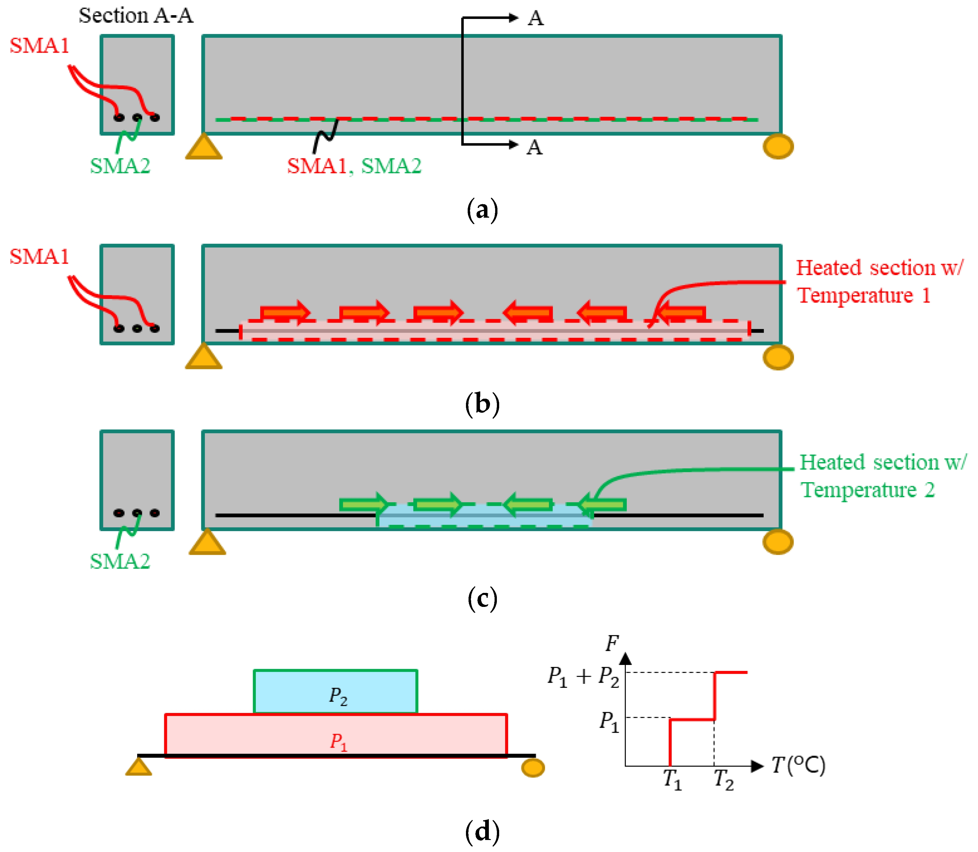
Figure 1 shows the general procedure of prestressing with hybrid SMA wires. The arrangement of the SMA wire and the manner in which prestressing force is transmitted to the structure are the same as those in the conventional pre-tensioning method.
Figure 1a shows an RC structure prestressed using SMA1 and SMA2, which have different austenite temperatures. If the austenite temperature of SMA2 is higher than that of SMA1, SMA2 will not exhibit the SME when heated to the austenite temperature of SMA1, T1. As illustrated in
Figure 1b,c, the hybrid SMA wires are heated to different temperatures. After the temperature reaches the austenite temperature, the SMA wires in the heated sections induces prestress in the RC beam. Upon differentiating the composition of the hybrid SMA wires and heated sections, the prestress induced by the SMEs shows a multi-step distribution, as illustrated in
Figure 1d.
Figure 2 shows the general stress distribution diagram at the bottom of a simply supported beam due to prestressing with hybrid SMA wires. Curve (1) in
Figure 2 represents the stress distribution without prestressing and curve (2) represents the stress distribution when the beam is prestressed with SMA1 only. Curve (3) represents the final stress distribution when the beam is prestressed with SMA2. These figures show that the stress is distributed uniformly over the length of the beam when it is prestressed with hybrid SMA wires. The proposed method offers the following advantages compared to the prestressing method that employs conventional tendons.
- (1)
If a member has two or more types of austenite temperatures, the SME can be controlled in steps, where the number of steps is equal to the number of austenite temperatures. Efficient prestressing is possible if it can be performed in several stages as needed during the construction phase or during the service phase according to the additionally required load-carrying capacity.
- (2)
The conventional pre-tensioning method introduces prestress through the elimination of tendon restraints after the design strength of the structure is attained. Therefore, re-tensioning is impossible. However, with the proposed prestressing technique, the timing of prestressing can be selected by adjusting the stage of SME expression. In addition, strains occurring in the SMA wires during service can be used for further re-tensioning.
3. Multi-Step Shape Recovery Test
3.1. Test Vasriabe and Specimens
Before conducting prestressing experiments using the hybrid SMA wires, the behaviors of the materials constituting the hybrid SMA wires should be identified. To this end, a multi-stepwise shape recovery test observes the deformation behavior of the SMA wire according to the SME caused by the heat applied in the chamber. To evaluate ranges of austenite temperature of SMA wires and to confirm the behavior of multi-stepwise shape recovery, three specimens for each of four types of wires were fabricated; two types of SMA wires and two types of hybrid SMA wires. The comparative test for each type of SMA is an experiment to confirm the austenite temperature of individual SMA. Hybrid SMA wires are tested to compare the behaviors of different SMA combinations. Two types of NiTi SMA wires were used. The material properties of the wires used in this study are shown in
Table 1 and
Figure 3. The stress–strain relationship of SMA wires is different from that of conventional structural steel, in that the yield behavior appears twice in case of the SMA wires. It may appear differently depending on the manufacturing method and chemical composition of the SMA wire. The SMA wire used in this study has a primary yield point at approximately 150 MPa and a secondary yield point at approximately 800 MPa. The estimated tensile strength of this wire was approximately 1000 MPa.
The two major test variables in this study were single wire and hybrid wire. Single-wire specimens were used to check the austenite temperature required to activate the SME of individual SMA wires. Although the manufacturer had provided these values, to double check and prevent any error, we confirmed the austenite temperature experimentally by using a heating chamber. In addition, we conducted experiments to compare SMA wire behavior in the single-wire state with that in a hybrid wire state. As shown in
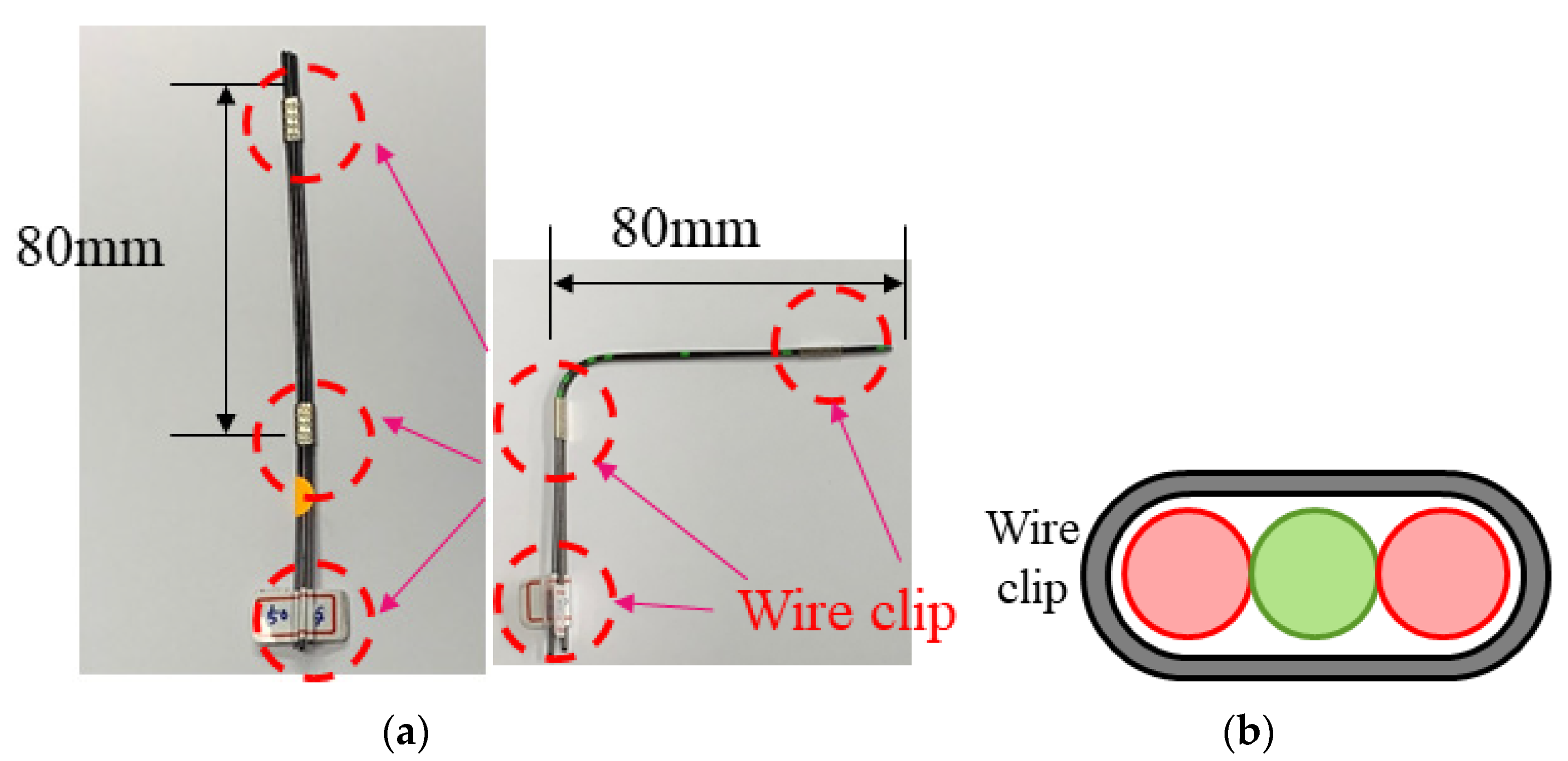
Figure 4a,b, a hybrid wire is a mechanical combination of three wires. Hybrid-wire experiments were performed to verify whether the behaviors of the individual constituent wires were combined. Here, combined behavior implies that the SME effect is expressed in a stepped manner as to the heating temperature reaches the austenite temperatures of the individual constituent. Three specimens were prepared for each variable to ensure the validity of the experimental results.
Table 2 summarizes the types of specimens.
3.2. Test Set-Up and Vision System Instrumentation
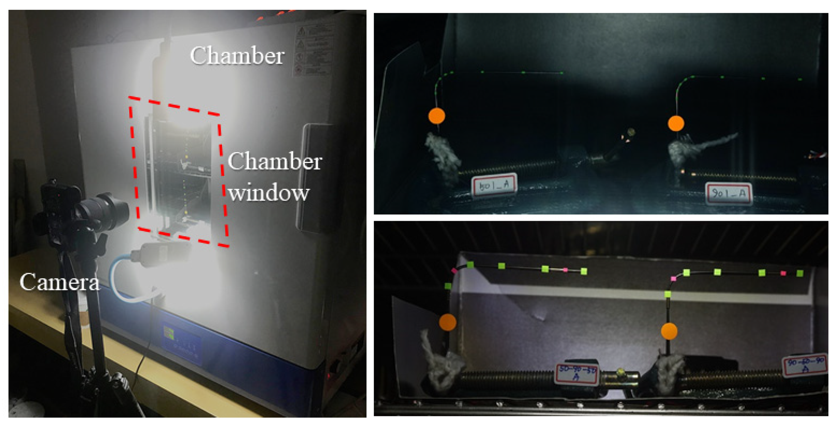
Figure 5 shows the installation of the test specimen for the heating test. The specimens were bent into an L-shape before heating and the lower end of the sample was fixed inside the chamber. A colored target was attached to the specimen, to facilitate easy observation of deformation of the specimen heated in the chamber by using an image processing method. If only one specimen is heated at a time, errors may occur in the results owing to differences in temperature control. Therefore, all four types of specimens, which composed one set, were heated simultaneously. The prestressing technique proposed in this study employs a hybrid SMA consisting of two or more types of SMAs. Any change in the behavior of a specific SMA at temperatures other than its austenite temperature it can be ascribed to errors in the prestressing process. Therefore, we increased the chamber temperature from approximately 25 to 105 °C to examine SMA behavior over a wide temperature range. Then, we decreased chamber temperature to 80 °C.
Figure 6 shows the variation in chamber temperature.
Figure 7a,b show the notation of the characteristic values in the heating temperature-displacement curves.
3.3. Test Result
In this experiment, we attempted to examine the shape recovery behavior under heat of the SMA wires used in this study. Specifically, we examined the temperature-displacement relationship and compared the temperatures at which SME occurred across the different combinations of SMA wires.
Figure 8a,b show the shape recovery of the NiTi50 and 90-50-90 specimens with increasing temperature. When the material reached the austenite temperature, all deformations started to recover. Especially, in case of the 90-50-90 hybrid wire, shape recovery occurred not only below 60 °C but also above 70 °C.
Table 3 summarizes the shape recovery temperatures and the displacements that occurred with recovery. Shape recovery start temperature (
) and shape recovery end temperature (
) are listed for individual wires. For the hybrid wire, the temperatures of the two-stage shape recovery behavior are denoted
,
,
, and
.
Figure 9 and
Figure 10 show the heating temperature-displacement relationship of the test specimen. The displacement at the end of the test specimen was measured using an image processing method.
In the results obtained for the single wire, both NiTi50 and NiTi90 showed noticeable deformation recovery in a specific temperature range. Both specimens exhibited a certain level of displacement before the shape recovery began, probably because thermal expansion was triggered as soon as the specimen was heated. Therefore, the displacement generated before the start of shape recovery for NiTi90 is greater than that for NiTi50. The austenite temperature measured in the experiment was different from the austenite temperature provided by the manufacturer. The austenite temperature specification of NiTi50 was 50 °C, but the experimental results showed that on average, shape recovery started and ended at 45.8 °C (91.7% of specification) and 67.9 °C (135.8% of specification), respectively. The austenite temperature specification for NiTi90 was 90 °C, but the experimental results showed that on average shape recovery started and ended at 77.5 °C (86.1% of specification) and 102.4 °C (113.8% of specification), respectively. Because the austenite temperature values provided by the manufacturer represent the average values of the experimentally determined start and end temperatures of shape recovery, they may be useful when designing structural applications with the hybrid wire configuration. However, an inaccurate shape recovery temperature may lead to an error in the amount of prestress introduced. Therefore, it is necessary to confirm the shape recovery temperature when prestress a structure by using SMA wires.
In the results obtained using the hybrid wires, the 50-90-50 and 90-50-90 specimens exhibited the multi-step shape recovery behavior, as was intended in this study. Depending on the proportion of NiTi90 in the hybrid wire, the first shape recovery step tended to restrain the shape recovery of NiTi50. The difference in displacements generated in the first shape recovery step between the single wire and the hybrid wire confirmed this constraint. The results in
Table 3 show that as the proportion of NiTi90 increases, the displacement generated in the first shape recovery step decreases. After the first shape recovery step, no shape recovery was seen at 68–78 °C. Therefore, this temperature interval can be used to distinguish the first and second steps of the multi-step shape recovery behavior. The second shape recovery step can be ascribed to NiTi90, the shape recovery temperature range of which similar to that of single-wire NiTi90. However, similar to the first shape recovery step, the second shape recovery step tended to restrain the shape recovery of NiTi90 depending on the proportion of NiTi50. Despite this restraining behavior, the final extent of recovery from deformation was the same for the single and hybrid wires. The shape recovery test verified the shape recovery behavior of the single SMA wires and the hybrid SMA wire. Depending on the temperature, the SME of the hybrid SMA wire could be partially controlled. Therefore, the applicability of the multi-step prestressing method to be evaluated in this study was confirmed. In the next section, we will perform a multi-step prestressing test based on the experiments performed in this section.
4. Multi-Step Prestressing Test
4.1. Test Variables and Specimens
In this section, we describe a multi-step prestressing test that was conducted with a prestrained hybrid SMA wire to confirm the applicability of the multi-step recovery behavior obtained in the previous section. The multi-step prestressing test was performed by measuring the amount of prestress introduced according to the SME triggered by heating in the chamber. Heating the specimen causes the concrete to thermally expand before SME starts to appear. Then, when the SMA wire reaches the shape recovery temperature, prestress is introduced into the test specimen. If the thermal expansion of concrete is not distinguished from the measurement result, our analysis of the experimental data will be compromised. Therefore, in this experiment, the main specimen including the SMA wire and a dummy specimen excluding the SMA wire were fabricated to help us distinguish the strain generated by the thermal expansion of concrete from the measured data. The hybrid SMA wire used in the experiment consisted of two types of SMA wires (NiTi50 and NiTi90), as described in the previous section. The specifications of the test specimens used in this experiment are listed in
Table 4 and
Figure 11. Three specimens were fabricated to check the repeatability of the results.
Before fabrication of the SMA wire specimens, the individual SMA wires were tensioned with a universal testing machine to induce residual strain in the SMA wires. This residual strain was used to introduce prestress. The diameter of the SMA wire used in this study was 1 mm. Because the wire was too thin, it was difficult to measure the strain induced in the wire with an extensometer. Therefore, we measured strain by using the image processing method. A tension force of 250 N was applied to the wire was 250 N.
Figure 12a,b show the experimental set-up and the load-strain curves measured at the time of introducing residual strain. Residual strains of 0.059 and 0.049 were induced in NiTi50 and NiTi90 wires, respectively.
If an SMA wire embedded in a concrete girder has anchorage parts, it will be possible to effectively introduce prestress. Therefore, in this study, both ends of the SMA wire were bent in J-shape, as shown in
Figure 13, to act as anchorages. Jung et al. [
28] evaluated the pull-out resistance of SMA wire anchorages with J-shaped ends. They derived Equation (1) to calculate the anchorage pull-out resistance. Equation (1) consists of three parts. The first part represents the effect of the embedded shape, the second part the SME, and the last part the effect of the adhesive force.
where,
denotes the pull-out resistance,
the number of J-shaped ends,
the number of SMA wires,
the length of the wire in anchorage,
the number of wires that have adhesive force, and
the bond length.
,
, and
are constants of the effect that improve the pull-out resistance [
28]. According to Equation (1), the pull-out resistance of the anchorage of the specimen is 901.8 N.
Table 5 lists the separated pull-out resistance values calculated using Equation (1).
4.2. Test Set-Up and Measurement
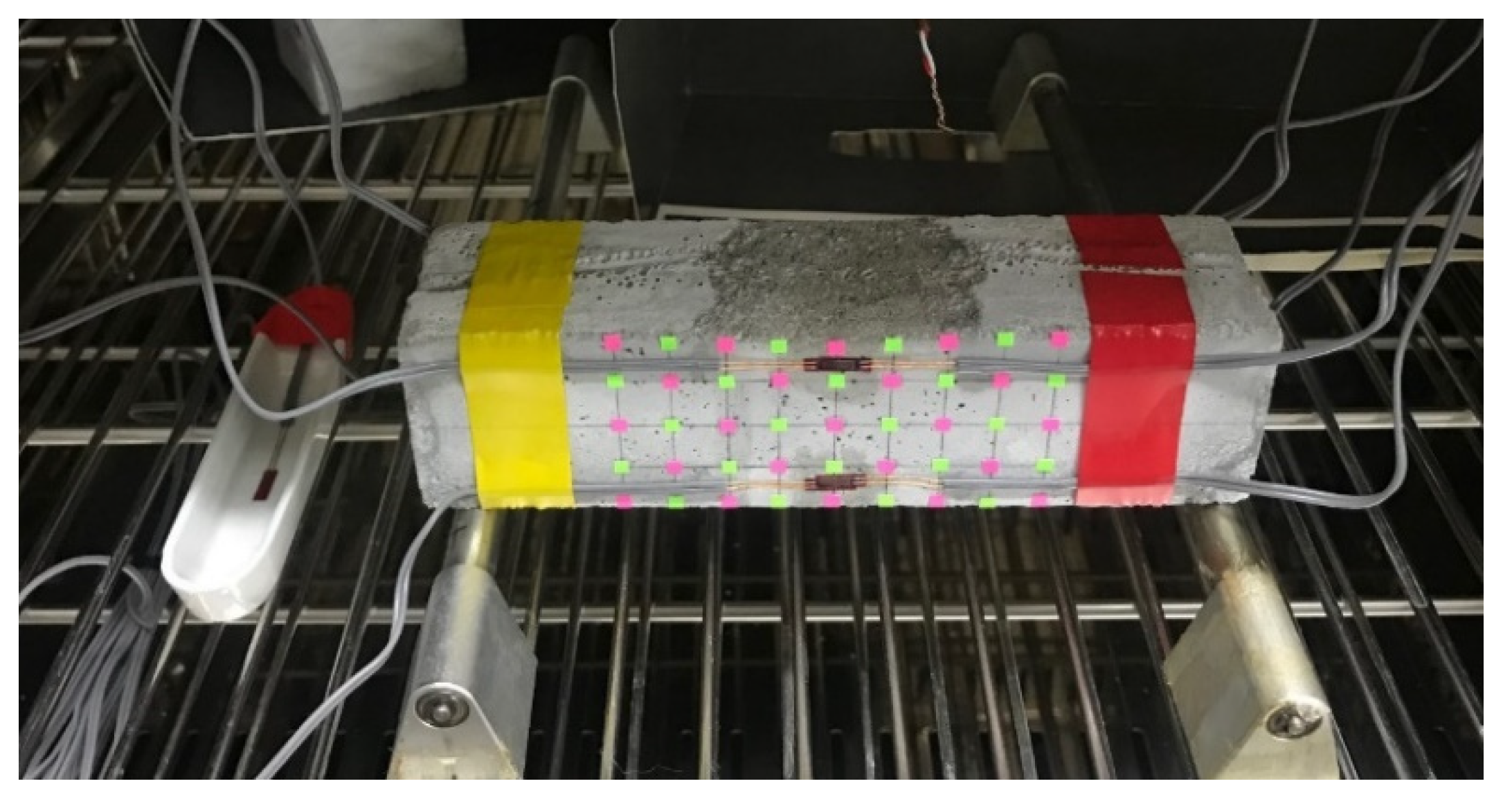
Figure 14 shows the specimen set-up for the multi-step prestressing test. The specimens were equipped with a thermocouple and strain gauge. The experimental set-up consisted of a dummy specimen and a main specimen in one set, which were heated simultaneously in the heating chamber. The thermocouples were installed at the center of the specimens. Strain gauges were attached on the sides of the specimens. The gauge factor of the strain gauge varied depending on the room temperature. A dummy strain gauge was placed next to the main specimen to calibrate the strain noise at high temperatures. As in case of the shape recovery test in the previous section, the purpose of this experiment is to identify the multi-step shape recovery behavior. In this experiment, we aim to introduce the multi-step prestress into a concrete girder. Therefore, in the multi-step prestressing test, heating experiments were performed in two steps as shown in
Figure 15. In each step, the amount of prestress was measured after heating and cooling the specimens. In the first step, the specimens were heated from 25 to 65 °C and then cooled to 25 °C. In the experiments described in the previous Section, the austenite temperature of NiTi50 was 43–68 °C. However, the maximum heating temperature in the first step was set to 65 °C to prevent any SME in NiTi90 due to overheating. In the second step, the maximum heating temperature was set to 105 °C considering the austenite temperature range of NiTi90.
4.3. Test Result
Figure 16 and
Table 6 show and summarize the strain-temperature relationships observed in the experiment. The experimental results were divided into step 1 and step 2 based on the heating step. As shown in
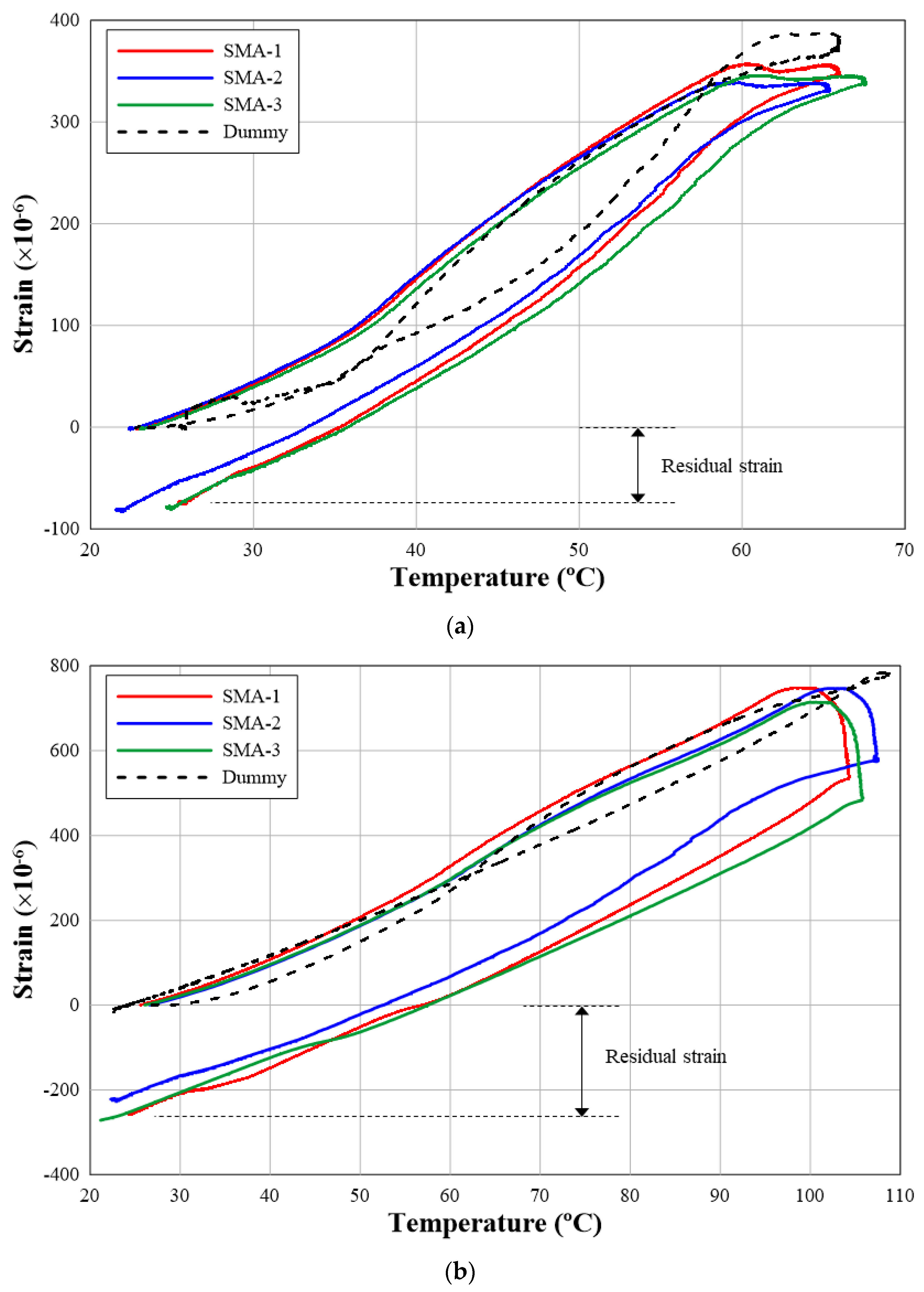
Figure 16, thermal expansion occurs in the specimen as the heating temperature increases, and thus, the strain gauge shows tensile strain. After the heating temperature peaks, the tensile strain decreases as cooling commences. In case of the dummy specimens, most of the tensile strain generated by heating was negated as the specimen cooled completely. Even the SMA specimens stretched when they were heated. In steps 1 and 2, the SMA specimens showed 5%–10% lower strain than the dummy specimen at the maximum heating temperature. Because the SME of SMA is active at the maximum heating temperature, compressive force is applied to the SMA specimen. Therefore, the maximum tensile stress of the SMA specimens is smaller than that of the dummy specimen, because the compressive force is generated by the SMA and acts against thermal expansion of the concrete sample. The compression strain remained as the SMA specimen cooled. In step 1, a residual strain of −80με was generated, and in step 2, a residual strain of −252με was generated. These residual strains were generated because the SME was activated in the heating step. When compared with the behavior of the dummy specimen, it was confirmed that the residual strain in the SMA specimen was generated as the thermal expansion strain generated in the heating step disappeared under cooling.
Figure 17 integrates the prestress records in steps 1 and 2. The final prestress introduced over the two steps averaged −331με. On average, 24% of the total residual strain was generated in step 1. The SME of NiTi50 was observed in Step 1. NiTi50 accounted for 33% of the total wire quantity. Therefore, the ratio of prestress in step 1 to the total prestress is similar to the ratio of NiTi50 in the hybrid SMA wire. However, there is a difference of about 9%, which means that NiTi90 resisted compressive forces as well as concrete sections when compressive force was generated in step 1. Therefore, sample stiffness may increase slightly owing to the restraint on NiTi90. As a result, the ratio of the prestress in Step 1 is smaller than the ratio of NiTi50 in the hybrid SMA wire. Steps 1 and 2 obtained in this small simulation can be considered as representing the situation of each construction stage in the actual structure. In addition, steps 1 and 2 are the results confirming that the prestress to be introduced can be adjusted in stages depending on the desired member or location. Therefore, the applicability of multi-step prestressing with hybrid SMA wires to be evaluated in this study was confirmed through the multi-step prestressing test performed in this section.
5. Conclusions
To improve the conventional prestressing technique, we conceptualized a multi-step prestressing technique with a hybrid SMA wire. The applicability of the proposed technique was verified through multi-step shape recovery behavior evaluation and multi-step prestressing tests. In the multi-step shape recovery tests, hybrid SMA wires were fabricated by combining two types of SMA wires: NiTi50 and NiTi90. Shape recovery behaviors that accompanied changes in temperature were evaluated using an image processing method. In the multi-step prestressing tests, the hybrid SMA wire specimens and the dummy specimen were heated simultaneously to ensure that the prestress was introduced in multiple steps according to the SME of the hybrid SMA wire. The conclusions of this study are as follows.
The shape recovery test verified the shape recovery behavior of the single SMA wires and the hybrid SMA wire. In the single-wire experiment, we evaluated the austenite temperature range in which the SMEs of the NiTi 50 wire and NiTi 90 wires were activated. The hybrid SMA wire, which was constituted of NiTi50 and NiTi90 wires joined using mechanical connectors, showed no shape recovery at 68–78 °C. This range represents the interval between the austenite temperatures of NiTi50 and NiTi90. Therefore, we could distinguish between the first and the second shape recovery steps based on the temperature range.
The multi-step prestressing test showed that the SMEs of NiTi50 and NiTi90 appeared in each of the two stages—step 1 corresponding to 25–65 °C and step 2 corresponding to 25–105 °C—thus indicating that the prestress was introduced in each step. When compared with the dummy specimens without any embedded SMA wires, the thermal expansion of the test specimen was similar during the initial heating phase. However, unlike the dummy specimens, residual compressive strain was observed in the specimens with embedded SMA wires after the specimens were cooled. Therefore, the applicability of the proposed multi-step prestressing with hybrid SMA wire was verified.
This study aimed to explore the basic concept of hybrid SMA wires. Therefore, we conducted small-scale experiments with limited variables and limited number of specimens. Future studies should explore diverse SMA wire materials and wire diameters, building upon the specimen sizes examined in this study. Furthermore, costs of SMA wires should be considered from the viewpoint of their use in practical applications. In this study, NiTi SMA, which can be supplied relatively easily, was used because it was a small-scale experiment. However, NiTi SMA is not suitable for actual application to realized structures because of its high material cost. Therefore, future studies should compare more economical SMA wires, such as Fe-based SMA wires. From these future studies, it will be possible to get a better understanding of the practical applications.
Author Contributions
Conceptualization, C.-Y.J. and J.-H.L.; methodology, C.-Y.J. and J.-H.L.; investigation, T.-R.W.; resources, J.-H.L.; data curation, T.-R.W.; writing—original draft preparation, T.-R.W.; writing—review and editing, C.-Y.J.; visualization, T.-R.W.; supervision, J.-H.L.; project administration, C.-Y.J. and J.-H.L.; funding acquisition, C.-Y.J. All authors have read and agreed to the published version of the manuscript.
Acknowledgments
This research was supported by the Basic Science Research Program through the National Research Foundation of Korea (NRF) and funded by the Ministry of Education (NRF-2017R1C1B1012747).
Conflicts of Interest
The authors declare no conflict of interest.
References
- Kabir, M.Z.; Tavousi, T.B. Closed-form solution for thermal, mechanical, and thermo-mechanical buckling and post-buckling of SMA composite plates. Compos. Struct. 2017, 168, 535–548. [Google Scholar] [CrossRef]
- Ghaznavi, A.; Shariyat, M. Non-linear layerwise dynamic response analysis of sandwich plates with soft auxetic cores and embedded SMA wires experiencing cyclic loadings. Compos. Struct. 2017, 171, 185–197. [Google Scholar] [CrossRef]
- Soltanieh, G.; Kabir, M.Z. Snap instability of shallow laminated cylindrical shells reinforced with functionally graded shape memory alloy wires. Compos. Struct. 2017, 180, 581–595. [Google Scholar] [CrossRef]
- Janke, L.; Czaderski, C.; Motavalli, M.; Ruth, J. Applications of shape memory alloys in civil engineering structures—Overvie, limits and new ideas. Mater. Struct. 2005, 38, 578–592. [Google Scholar]
- Moser, K.; Bergamini, A.; Christen, R.; Czaderski, C. Feasibility of concrete prestressed by shape memory alloy short fibers. Mater. Struct. 2005, 38, 593–600. [Google Scholar] [CrossRef]
- Shahverdi, M.; Czaderski, C.; Motavalli, M. Iron-based shape memory alloys for prestressed near-surface mounted strengthening of reinforced concrete beams. Constr. Build. Mater. 2016, 112, 28–38. [Google Scholar] [CrossRef]
- Maji, A.K.; Negret, I. Smart prestressing with shape memory alloy. J. Eng. Mech. 1998, 124, 1121–1128. [Google Scholar] [CrossRef]
- Krstulovic-Opara, N.; Naaman, A.E. Self-stressing fiber composites. ACI Struct. J. 2000, 97, 2335–2344. [Google Scholar]
- Soroushian, P.; Ostowari, K.; Nossoni, A.; Chowdhury, H. Repair and strengthening of concrete structures through application of corrective posttensioning forces with shape memory alloys. J. Transp. Res. Board. 2001, 1770, 20–26. [Google Scholar] [CrossRef]
- Li, H.; Liu, Z.Q.; Ou, J.P. Behavior of a simple concrete beam driven by shape memory alloy wires. Smart Mater. Struct. 2006, 15, 1039–1046. [Google Scholar] [CrossRef]
- Lee, K.J.; Lee, J.H.; Jung, C.Y.; Choi, E. Crack-closing performance of NiTi and NiTiNb fibers in cement mortar beams using shape memory effects. Compos. Struct. 2018, 202, 710–718. [Google Scholar] [CrossRef]
- Lee, J.H. Influence of concrete strength combined with fiber content in the residual flexural strengths of fiber reinforced concrete. Compos. Struct. 2017, 168, 216–225. [Google Scholar] [CrossRef]
- Deng, Z.; Li, Q.; Sun, H. Behavior of concrete beam with embedded shape memory alloy wires. Eng. Struct. 2006, 28, 1691–1697. [Google Scholar] [CrossRef]
- Li, H.; Liu, Z.Q.; Ou, J.P. Study on reinforced concrete beams strengthened using shape memory alloy wires in combination with carbon-fiber-reinforced polymer plates. Smart Mater. Struct. 2007, 16, 2550–2559. [Google Scholar] [CrossRef]
- Li, L.; Li, Q.; Zhang, F. Behavior of smart concrete beams with embedded shape memory alloy bundles. J. Intell. Mater. Syst. Struct. 2007, 18, 1003–1014. [Google Scholar] [CrossRef]
- Saiidi, M.; Sadrossadat-Zadeh, M.; Ayoub, C.; Itani, A. Pilot study of behavior of concrete beams reinforced with shape memory alloys. J. Mater. Civ. Eng. 2007, 19, 454–461. [Google Scholar] [CrossRef]
- Li, H.; Liu, Z.Q.; Ou, J.P. Experimental study of a simple reinforced concrete beam temporarily strengthened by SMA wires followed by permanent strengthening with CFRP plates. Eng. Struct. 2008, 30, 716–723. [Google Scholar] [CrossRef]
- Choi, E.; Kim, D.J.; Hwang, J.H.; Kim, W.J. Prestressing effect of cold-drawn short NiTi SMA fibres in steel reinforced mortar beams. Smart Mater. Struct. 2016, 25, 1–13. [Google Scholar] [CrossRef]
- Czaderski, C.; Shahverdi, M.; Brönnimann, R.; Leinenbach, C.; Motavalli, M. Feasibility of iron-based shape memory alloy strips for prestressed strengthening of concrete structures. Constr. Build. Mater. 2014, 56, 94–105. [Google Scholar] [CrossRef]
- Cladera, A.; Weber, B.; Leinenbach, C.; Czaderski, C.; Shahverdi, M.; Motavalli, M. Iron-based shape memory alloy for civil engineering structures. Constr. Build. Mater. 2014, 63, 281–293. [Google Scholar] [CrossRef]
- Lee, W.J.; Weber, B.; Leinenbach, C. Recovery stress formation in a restrained Fe–Mn–Si-based shape memory alloy used for prestressing or mechanical joining. Constr. Build. Mater. 2015, 95, 600–610. [Google Scholar] [CrossRef]
- Rojob, H.; El-Hacha, R. Self-prestressing using iron-based shape memory alloy for flexural strengthening of reinforced concrete beams. ACI Struct. J. 2017, 114, 523. [Google Scholar] [CrossRef]
- Hong, K.; Lee, S.; Han, S.; Yeon, Y. Evaluation of Fe-based shape memory alloy (Fe-SMA) as strengthening material for reinforced concrete structures. Appl. Sci. 2018, 8, 730. [Google Scholar] [CrossRef]
- Zheng, B.; Dawood, M. Fatigue crack growth analysis of steel elements reinforced with shape memory alloy (SMA)/fiber reinforced polymer (FRP) composite patches. Compos. Struct. 2017, 164, 158–169. [Google Scholar] [CrossRef]
- Gholampour, A.; Ozbakkaloglu, T. Understanding the compressive behavior of shape memory alloy (SMA)-confined normal- and high-strength concrete. Compos. Struct. 2018, 202, 943–953. [Google Scholar] [CrossRef]
- Hong, C.; Qian, H.; Song, G. Uniaxial compressive behavior of concrete columns confined with superelastic shape memory alloy wires. Materials 2020, 13, 1227. [Google Scholar] [CrossRef] [PubMed]
- Kim, M.K.; Kim, D.J.; Chung, Y.-S.; Choi, E. Effects of a short heat treatment period on the pullout resistance of shape memory alloy fibers in mortar. Materials 2019, 12, 2278. [Google Scholar] [CrossRef]
- Jung, C.Y.; Woo, T.R.; Lee, J.H.; Cheung, J.H. Evaluation of the pull-out resistance of the SMA wire connector. J. Korea Inst. Struct. Maint. Insp. 2019, 23, 130–137. [Google Scholar]
Figure 1.
General application procedure of prestressing method using hybrid shape memory alloy (SMA) wires: (a) prestressed concrete girder with hybrid SMA wires; (b) heating of hybrid SMA wire to temperature 1; (c) heating of hybrid SMA wire to temperature 2; (d) final prestressing force distribution and multi-step prestressing force in section A.
Figure 2.
Stress distribution due to the prestressing method with hybrid SMA wires.
Figure 2.
Stress distribution due to the prestressing method with hybrid SMA wires.
Figure 3.
Stress-strain curves of SMA wires.
Figure 3.
Stress-strain curves of SMA wires.
Figure 4.
Details of specimens: (a) unbent hybrid SMA wire and bent hybrid SMA wire; (b) section of specimen at wire clip.
Figure 4.
Details of specimens: (a) unbent hybrid SMA wire and bent hybrid SMA wire; (b) section of specimen at wire clip.
Figure 5.
Test and measurement set-up and specimens in chamber.
Figure 5.
Test and measurement set-up and specimens in chamber.
Figure 6.
Chamber temperature variation.
Figure 6.
Chamber temperature variation.
Figure 7.
Notations of characteristic value in heating temperature–displacement curves: (a) single wire and (b) hybrid wire.
Figure 7.
Notations of characteristic value in heating temperature–displacement curves: (a) single wire and (b) hybrid wire.
Figure 8.
Shape recovery of specimens depending on austenite temperature: (a) single wire and (b) hybrid wire.
Figure 8.
Shape recovery of specimens depending on austenite temperature: (a) single wire and (b) hybrid wire.
Figure 9.
Temperature-displacement relationship of single wire: (a) NiTi50; (b) NiTi90.
Figure 9.
Temperature-displacement relationship of single wire: (a) NiTi50; (b) NiTi90.
Figure 10.
Temperature-displacement relationship of hybrid wire: (a) 50-90-50; (b) 90-50-90.
Figure 10.
Temperature-displacement relationship of hybrid wire: (a) 50-90-50; (b) 90-50-90.
Figure 11.
Dimensions of specimen (unit: mm).
Figure 11.
Dimensions of specimen (unit: mm).
Figure 12.
Results of residual strain: (a) test set-up for residual strain; (b) load-strain curves.
Figure 12.
Results of residual strain: (a) test set-up for residual strain; (b) load-strain curves.
Figure 13.
Hybrid SMA wire.
Figure 13.
Hybrid SMA wire.
Figure 15.
Chamber temperature variation.
Figure 15.
Chamber temperature variation.
Figure 16.
Strain-temperature curve: (a) step 1; (b) step 2.
Figure 16.
Strain-temperature curve: (a) step 1; (b) step 2.
Figure 17.
Simultaneously plotted strain-temperature curve.
Figure 17.
Simultaneously plotted strain-temperature curve.
Table 1.
Material properties of the SMA wire, as provided by the manufacturer.
Table 1.
Material properties of the SMA wire, as provided by the manufacturer.
| Type | Austenite Temperature | Chemical Composition (%) |
|---|
| Ti | Ni | Co | Cu | Fe | Nb | C | Others |
|---|
| NiTi50 | 50 °C ± 5 °C | Bal. | 55.89 | 0.050 | 0.010 | 0.050 | 0.025 | 0.046 | Each < 0.10 |
| NiTi90 | 90 °C ± 5 °C |
Table 2.
Types of specimens.
Table 2.
Types of specimens.
| Specimen | Type | Number of Wires | Quantity |
|---|
| NiTi50 | Single | NiTi50: 1ea | 3 |
| NiTi90 | Single | NiTi90: 1ea | 3 |
| NiTi50-90-50 | Hybrid | NiTi50: 2ea, NiTi90: 1ea | 3 |
| NiTi90-50-90 | Hybrid | NiTi50: 1ea, NiTi90: 2ea | 3 |
Table 3.
Comparisons of results of shape recovery tests.
Table 3.
Comparisons of results of shape recovery tests.
| Specimen | Temperature (°C) | Displacement (mm) |
|---|
| | | | | | | |
| NiTi50 | 1 | 46.8 | 68.8 | - | - | 1.71 | 86.07 | - | - |
| 2 | 45.1 | 69.5 | - | - | 1.62 | 85.95 | - | - |
| 3 | 45.6 | 65.4 | - | - | 1.82 | 87.35 | - | - |
| Avg. | 45.8 | 67.9 | - | - | 1.72 | 86.46 | - | - |
| NiTi90 | 1 | 77.4 | 103.5 | - | - | 4.17 | 88.20 | - | - |
| 2 | 77.8 | 102.5 | - | - | 4.20 | 86.50 | - | - |
| 3 | 77.2 | 101.3 | - | - | 3.41 | 85.60 | - | - |
| Avg. | 77.5 | 102.4 | - | - | 3.93 | 86.77 | - | - |
| 50-90-50 | 1 | 45.3 | 72.0 | 80.5 | 105.5 | 2.13 | 77.64 | 78.32 | 87.47 |
| 2 | 42.5 | 65.5 | 78.6 | 101.3 | 2.25 | 78.50 | 78.73 | 85.46 |
| 3 | 42.5 | 66.3 | 80.1 | 98.7 | 2.65 | 80.47 | 80.49 | 88.59 |
| Avg. | 43.4 | 67.9 | 79.7 | 101.8 | 2.34 | 78.87 | 79.18 | 87.17 |
| 90-50-90 | 1 | 46.2 | 67.7 | 77.2 | 103.7 | 3.01 | 40.52 | 40.66 | 88.82 |
| 2 | 45.7 | 68.9 | 76.8 | 103.7 | 3.38 | 42.01 | 42.04 | 90.36 |
| 3 | 44.3 | 69.1 | 78.6 | 103.0 | 2.98 | 39.26 | 40.35 | 86.09 |
| Avg. | 45.4 | 68.6 | 77.5 | 103.5 | 3.10 | 40.60 | 41.00 | 88.40 |
Table 4.
Types of specimens.
Table 4.
Types of specimens.
| Specimen | Number of SMA Wires | Quantity |
|---|
| NiTi50 | NiTi90 |
|---|
| SMA | 2 | 4 | 3 |
| Dummy | - | - | 1 |
Table 5.
Separated pull-out resistance values according to mechanical behavior.
Table 5.
Separated pull-out resistance values according to mechanical behavior.
| Embedded Shape | SME | Adhesive Force | Total |
|---|
| 77.58 N | 336.29 N | 487.96 | 901.83 N |
Table 6.
Results of multi-step prestressing tests.
Table 6.
Results of multi-step prestressing tests.
| Specimen | Step 1 | Step 2 |
|---|
| Max Strain | Residual Strain | Max Strain | Residual Strain |
|---|
| SMA-1 | 358 | −76 | 748 | −258 |
| SMA-2 | 339 | −83 | 747 | −225 |
| SMA-3 | 346 | −80 | 714 | −272 |
| Dummy | 387 | −1 | 784 | −17 |
© 2020 by the authors. Licensee MDPI, Basel, Switzerland. This article is an open access article distributed under the terms and conditions of the Creative Commons Attribution (CC BY) license (http://creativecommons.org/licenses/by/4.0/).


