1. Introduction
Since its introduction in 1968, light-emitting diodes (LEDs) have become the most common optoelectronic components used in the industry. LED lamps have become more and more popular in daily lighting and have gradually replaced incandescent lamps. Compared with incandescent lamps, LED lamps are energy-saving and power-saving. However, it is necessary for LED lamps to improve the luminous efficiency and solve the disadvantages of heat dissipation. Only 15 to 20% of the input power for a LED lamp is converted into light energy, and the remaining power will be transformed into heat. Due to the high temperature generated by heat dissipation, the use of LED lamps in harsh environments may endanger the safety of human lives and property.
With the introduction of graphene, which was isolated and characterized in 2004 by Andre Geim and Konstantin Novoselov at the University of Manchester, the application of graphene ink for heat dissipation has often been discussed for electronic devices or components such as LED lamps, virtual reality devices and printed circuit board assembly (PCBA). For electronic products, the coatings should be effective or appropriate for heat dissipation, electrical resistance and surface adhesion, etc. In this study, NDG ink and its application for the coating of LED lamps were studied. The NDG ink in this research was tuned with a high electrical resistance and suitable for coating the LED lamps. The cooling efficiency is discussed for LED lamps with different cooling mechanisms such as fins and NDG coating. In addition, in this study, the NDG powder was tested to verify its properties.
2. Historical Review
Looking back on the studies by researchers and scholars, the literature review was divided into two main areas: graphene and LEDs. The graphene literature mainly introduces the manufacturing process, properties, and heterogeneous doped graphene, etc.; and the LED literature has been mainly discussed in terms of temperature measurement, thermal resistance, and thermal management to control waste heat.
2.1. Graphene Literature
In 2004, Andre Geim and Konstantin Novoselov [
1] of the University of Manchester, England used mechanical exfoliation to separate graphene from layered graphite. However, this method cannot accurately control the area of graphene and the number of layers was not uniform for mass production. Nowadays, there are many ways in which to make graphene. Later, many methods were developed for producing graphene [
2,
3,
4,
5]. Defects and ruptures were often found in the structure of graphene, so related doping methods were developed to repair the structure of graphene. In 2008, Giovannetti, Khomyakov, Brocks et al. doped graphene with metal contacts [
3]. Wei, Liu, Wang et al. used chemical vapor deposition (CVD) to synthesize nitrogen doping graphene in 2009 [
4]. In 2017, Ren exploited the method of pulsed laser deposition to produce nitrogen doping graphene [
5]. The development of graphene was very rapid. In 2010, Allen, Tung, and Kaner published a paper related to a historical review on graphene [
6].
In 2010, Ki Kang Kim et al. [
7] used chemical vapor deposition (CVD) to synthesize graphene films. The deposition of Au particles on the film was observed through an atomic force microscope and a scanning electron microscope. The size of the Au particles was 10–100 nm. At the same time, the film had a transmittance of 87%, and the surface resistance value was 150 Ω/sq. Generally, CVD needs to be performed at high temperature. In 2017, Jun-ichi Fujita et al. [
8] used a dilute methane vapor source and a molten gallium catalyst to produce high-quality graphene at a controlled ambient temperature of about 50 °C and 100 °C on sapphire and polycarbonate substrates. Based on this development, significant progress has been made in low-temperature graphene synthesis methods.
Liquid phase exfoliation mainly uses graphite blocks as a carbon source dispersed in a solvent. The solvent is usually N-methyl pyrrolidone (NMP) or dimethylformamide (DMF). Ultra-sonication is applied when molecules are adsorbed on the surface of graphite. Molecules oscillate in the liquid phase, allowing graphene to overcome van der Waals forces between the layers of graphite. There is no chemical oxidation effect or defect during the graphene stripping process, and the crystal quality of graphene is high. The CVD method requires ultrasonic vibration for tens of hours, which is very time-consuming. The peeled graphene is shattered to a size less than 1 um, and the graphene dispersion solution cannot produce a uniform single-layer graphene. Yenny Hernandez et al. [
9] indicated that the surface tension of the solvent for stripping graphene was about 40–50
which is the best range for graphene production. The thermal conductivity of NDG was studied by Goharshadi in 2015 [
10]. In the study, the effects of temperature and doping density of nitrogen on thermal conductivity were discussed. The results showed that the thermal conductivity of NDG will decrease as the temperature or the doping density of nitrogen increases. At room temperature (300 K), it showed that the thermal conductivity of NDG was in the range of 750–1300
for the doping density range of 0.5–7%. In 2010, Lin et al. [
11] used ammonia plasma exposure to investigate the features of NDG and showed that the electrical conductance of NDG decreased due to the creation of excess defects, which could be observed by the increase in the D peak intensity of the Raman spectrum.
Regarding the application of graphene to coating paints, Liang Tianyuan [
12] and others used a sol–gel method to make a conductive heat-dissipating composite coating, which contained graphene powder and polydimethylsiloxane. The graphene coating had a thermal conductivity four times better than that of the original polydimethylsiloxane coating and the graphene composite coating had a thermal conductivity of 1.02 W/mK. This graphene coating had hydrophobicity, excellent adhesion and hardness, and good performance for the actual coating.
2.2. Light Emitting Diode Literature
The first LED was developed in 1960. It was not until 1996 that Dr. Shuji Nakamura invented white LED to break through the long-term technical bottleneck. Since then, many LED-related issues have been studied by scholars [
13,
14]. For the application of LED, thermal management has always been an important issue. In 2007, Huber [
15] studied the technology of the thermal management for LED lamps. In 2012, X. Perpiñà [
16] et al. simulated the thermal model for LED lamps and analyzed the corresponding thermal management. The study used infrared cameras and thermocouples to monitor specific measurement points on LED lamps and driver boards. The experimental results were used to establish and verify the simulation model for the LED lamp. Using models of simplified electronic components and circuit boards, the thermal simulation of driver boards was built. According to the results of the measurements and thermal simulation by X. Perpiñà, the temperature of the LED lamp increased significantly, and the temperature of the LED circuit board was raised at a percentage of 15% with the environmental temperature of 22 °C. Glass fiber epoxy substrate is a common raw material in printed circuit boards and is made by several materials such as epoxy resin, glass fiber cloth, and copper foil. The PCB (printed circuit board) of the LED lamp was made by pressing, and the model number included G-10, FR-4, FR-5, etc.
Raccichini et al. [
17] investigated the electrochemical energy storage for graphene in 2015. In 2016, Raypah et al. [
18] studied the influence of the thermal conductivity on the temperature distribution for surface-mount device (SMD) LEDs of FR4 copper foil substrates, packed with an aluminum housing. The commercial software, FloEFD, was used for the thermal simulation. Meanwhile, the corresponding experiments used the current inputs of 50 and 100 mA for measuring the thermal parameters. The simulation and experimental results by Raypah showed that the LED lamp of an aluminum package with a power of 5 W had a lower thermal resistance and junction temperature. In 2017, Yin Zhang et al. [
19] synthesized a graphene epoxy composite material as a thermal interface material for LED lamps where the thermal performance and junction temperature of LED lamps were measured. The results showed that the thermal conductivity of graphene epoxy composites increased with the increase in the graphene mixing ratio. Taking 10 W power LED lamps as an example, the junction temperature could be reduced from 72 °C to 67 °C. In 2017, similar studies were published for the heat conduction of graphene as shown in [
12,
20].
3. Experiment Description
The properties of NDG were investigated using atomic force microscopy (AFM), x-ray photoelectron spectroscopy (XPS), Raman spectroscopy; and the tests of the NDG ink and NGC LED lamps were studied by the cross-cut adhesion test, four-point probe resistance measurement, integrating sphere, temperature measurement by thermal couples, etc.
3.1. Experiment of Nitrogen-Doped Graphene
The following tests explain the properties of NDG powder used in this study. The related test machine specifications are described below.
3.1.1. Atomic Force Microscopy (AFM)
In this study, AFM (Innova produced by Bruker) was used for the surface measurement of NDG. The etched silicon probe (ESP), had a specification of 0.2 N/m, 13 kHz, and Al reflective coating. The tip of the probe had a radius of 8 nm, height of 12.5 μm, and a set back from the end of the cantilever beam of 15 μm. The front angle, back angle, and side angel of the tip were 25°, 15°, and 22.5°, respectively.
3.1.2. X-Ray Photoelectron Spectroscopy (XPS) Analyzer
The XPS analyzer can be exploited for the composition analysis of powder, and a PHI 5000 VersaProbe by ULVAC-PHI Inc. was used to analyze the composition of NDG in this study. The diameter of the x-ray beam was less than 10 mm (20/80% knife edge). The sensitivity was greater than 4000 cps (0.6 eV, Ag 3 d5/2). The corresponding resolution of energy was less than 0.50 eV (Ag3 d5/2) or 0.85 eV (O=C–O, PET C1 s).
3.1.3. Micro-Raman Spectroscopy
In this study, the micro-Raman spectroscopy system consisted of a spectrometer (TRIAX 320, Jobin-Yvon, 1200 gr/mm grating), a thermoelectric cooling charged-coupled device (TE-cooling CCD) (ANDOR DU401A-F1, cooling temperature: −70 °C), a microscope (GX-71, OLYMPUS), and an unpolarized DPSS (Diode Pumping Solid State) laser [
21]. The wavelength of the Raman spectrum experiment was 514 nm, and the scanning range was 1000 cm
−1~3000 cm
−1 with the accuracy of ±1 cm
−1.
3.2. Nitrogen-Doped Graphene (NDG) Ink and NDG-Ink Coated (NGC) LED Lamp Experiment
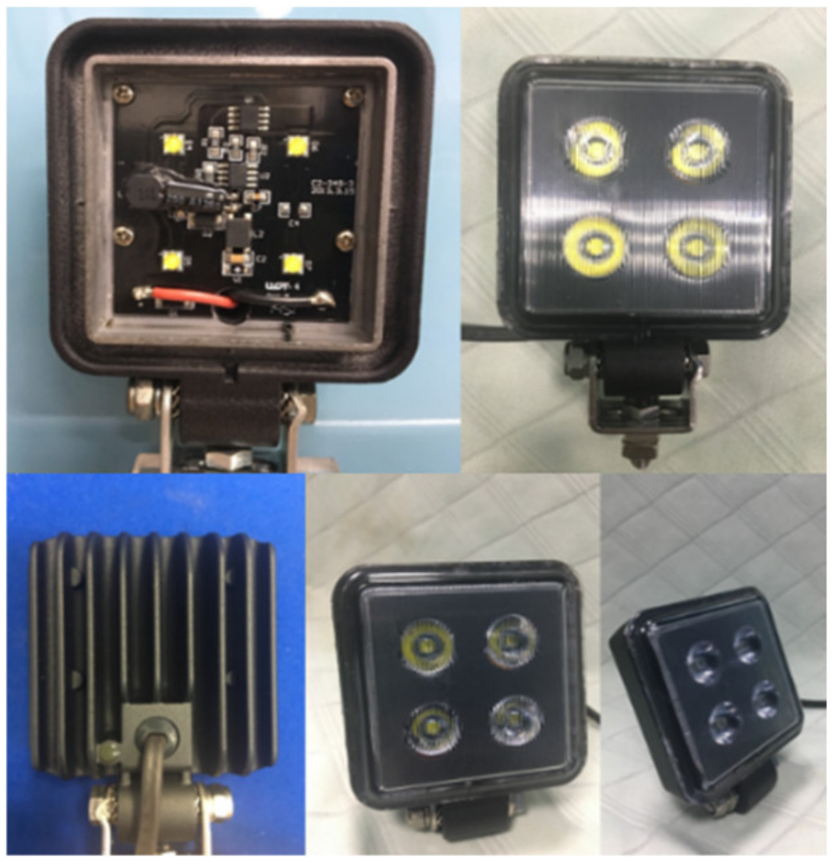
Figure 1 shows the commercial LED lamp used in this study. The LED lamp had integrated circuits (ICs) to control the input voltage and current. Therefore, in this study, the input voltage of 48 V was used and the corresponding outputs were measured.
3.2.1. Cross-Cut Adhesion Test
According to the ASTM D3359 specification, the cross-cut adhesion test uses a cross-cutting device or knife to produce a 10 × 10 small grid pattern on the coating of the paint. In the study, a knife (type 2087.5) produced by Zehntner was used for the cross-cut test. Following the ASTM standard, the cut line should be observed on the substrate. The vertical and horizontal lines had the same span of 1 mm. The tester then used a brush to clean the sample in the diagonal direction several times. Subsequently, the tester used 3M 600 tape to stick to the specimen, quickly pull up the 3M tape, counted the number of drops, and observed the pattern of the grid area. The tester could use a magnifying glass to observe the standard level of adhesion and judge the results.
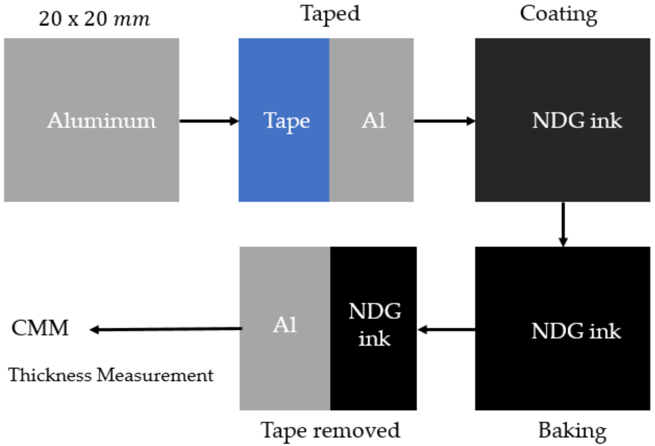
3.2.2. Four-Point Probe Resistance Measurement
In this experiment, the paint of the NDG ink (tuned with NDG powder) was spin-coated on a substrate of aluminum by the spin coater. The spin coating machine with a maximum speed of 6000 rpm operated for a time range of 1–99 s. The test piece was taped over half of the area. The test piece was then spin-coated with the NDG ink and then baked at 150 °C for 1 h on the heating platform. When the baking procedure was finished, the tape was removed from the test piece and the area under the removed tape was used as a reference for the thickness measurement of the NGD coating. The thickness was then measured by the 3D measuring machine. The thickness of the NDG coating was used as an input for the four-point probe resistance measurement. The probe head was plated with Au. The four-point probes were coaxially isolated and connected to the four-point probe holder. The test stand had a measuring range of 0.5 mΩ/cm~100 KΩ/cm, with a 6.5-digit display panel and serial ports, RS232 and USB, for data transmission.
3.2.3. Integrating Sphere
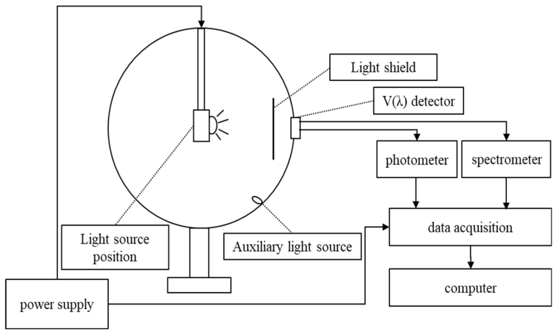
The integrating sphere system included the main integrating sphere, visual function detector, photometer, spectrometer, power supply module, and computer host, as shown in
Figure 2. The integrating sphere measurement can obtain parameters such as luminous flux, spectrum, color rendering, color temperature, and monitored inputs such as voltage, electricity, input power, etc.
The standard lamp for the experiment, model number OSRAM/HLX64640/150W-1, made corrections to the integrating sphere, as shown in
Figure 3. The luminous flux is an index for LED lamps, and the luminous flux emitted by LED lamps is expressed in lumen (lm). The ratio of the luminous flux to the power consumed represents the luminous efficiency (lm/W) of the LED lamp.
3.2.4. Temperature Measurement
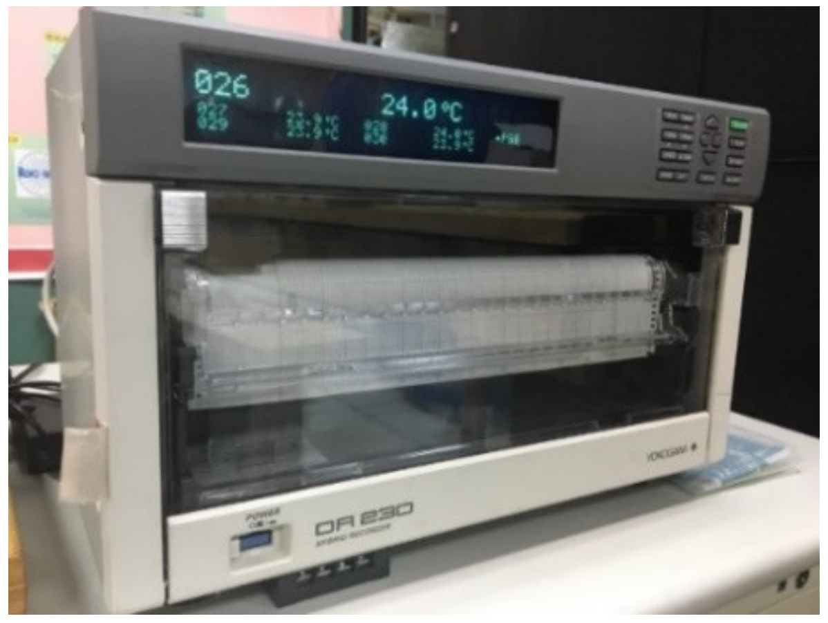
Thermocouples with a recorder were used to measure the temperature distribution for the LED lamp. In a sealed box of
, a DR230 temperature recorder, a hybrid multi-channel record, was used for the experiment, as shown in
Figure 4. The scanning time was 500 ms for up to 300 channels. Meanwhile, the record could be connected to the computer for data transmission and analysis. In the box, there were 30 points for the installation of thermal couples. In the experiment, the K-type of the thermal couple was used. The direct current (DC) regulated power supply was applied for the power input in the experiment. There were eight monitoring points for the LED lamp, as shown in
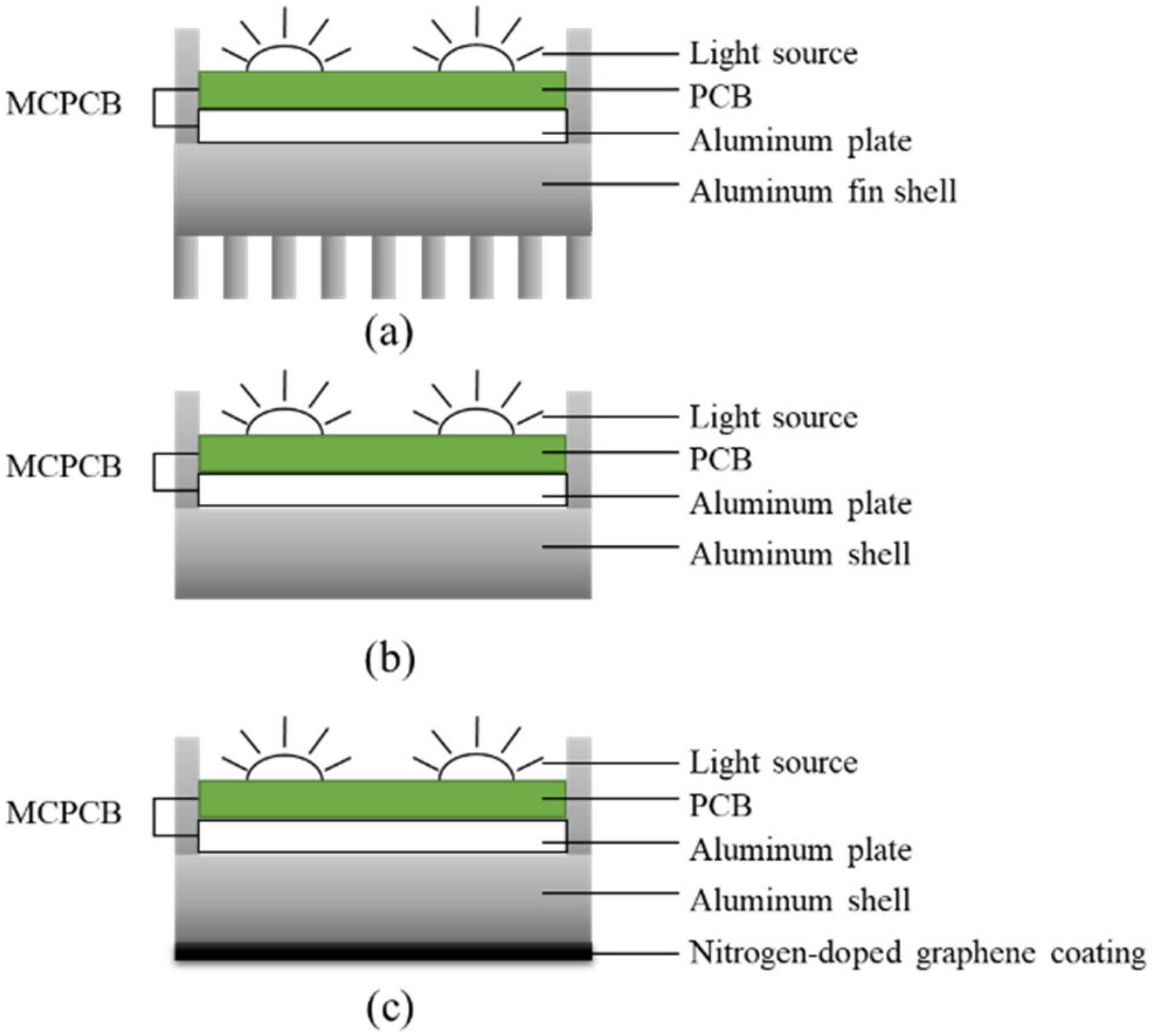
Figure 5. The LED lamps under investigation included the original lamp, fin-removed lamp, and NGC lamp, as shown in
Figure 6.
4. Results and Discussion
This study explored the properties and application of NDG. The LED lamps were investigated with NDG coatings. The detection and analysis of NDG powder included surface roughness, surface morphology, elemental composition, and Raman spectrum; for NDG ink painted on the LED lamp, the luminous flux was measured by integrating the lamp and the operating temperature was measured by thermocouples.
4.1. XPS Inspection for NDG Powder
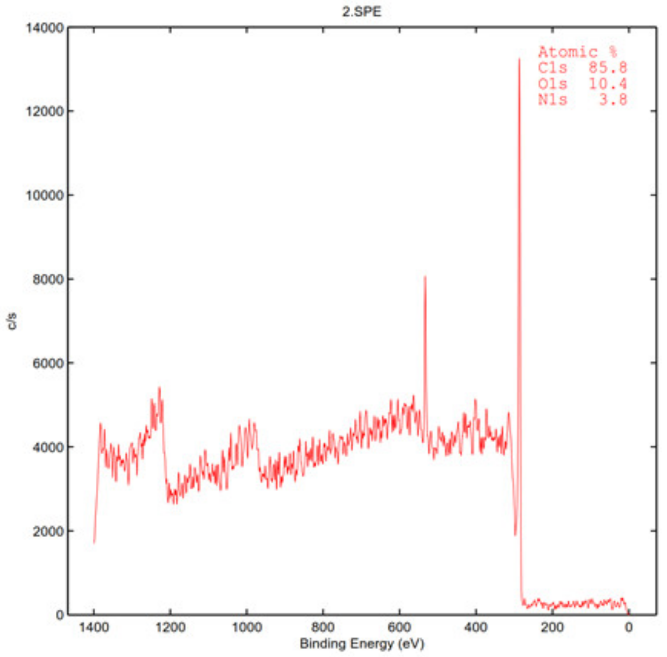
In this research, the NDG powder was compressed to produce the specimen. Surface profile and depth analysis of the specimen were performed, and a chemical composition analysis was operated for the C, O, and N elements. As shown in
Figure 7, it can be observed that the graphene used in this research did contain nitrogen. The XPS inspection measured the surface of the sample and provided the constitution and composition (by atomic level) of the NDG powder used in this study. Due to the NDG in the powder pattern, the composition of NDG by XPS could be used as the reference.
Table 1 shows the constitution and composition of the NDG in this study.
4.2. AFM Inspection for NDG Powder
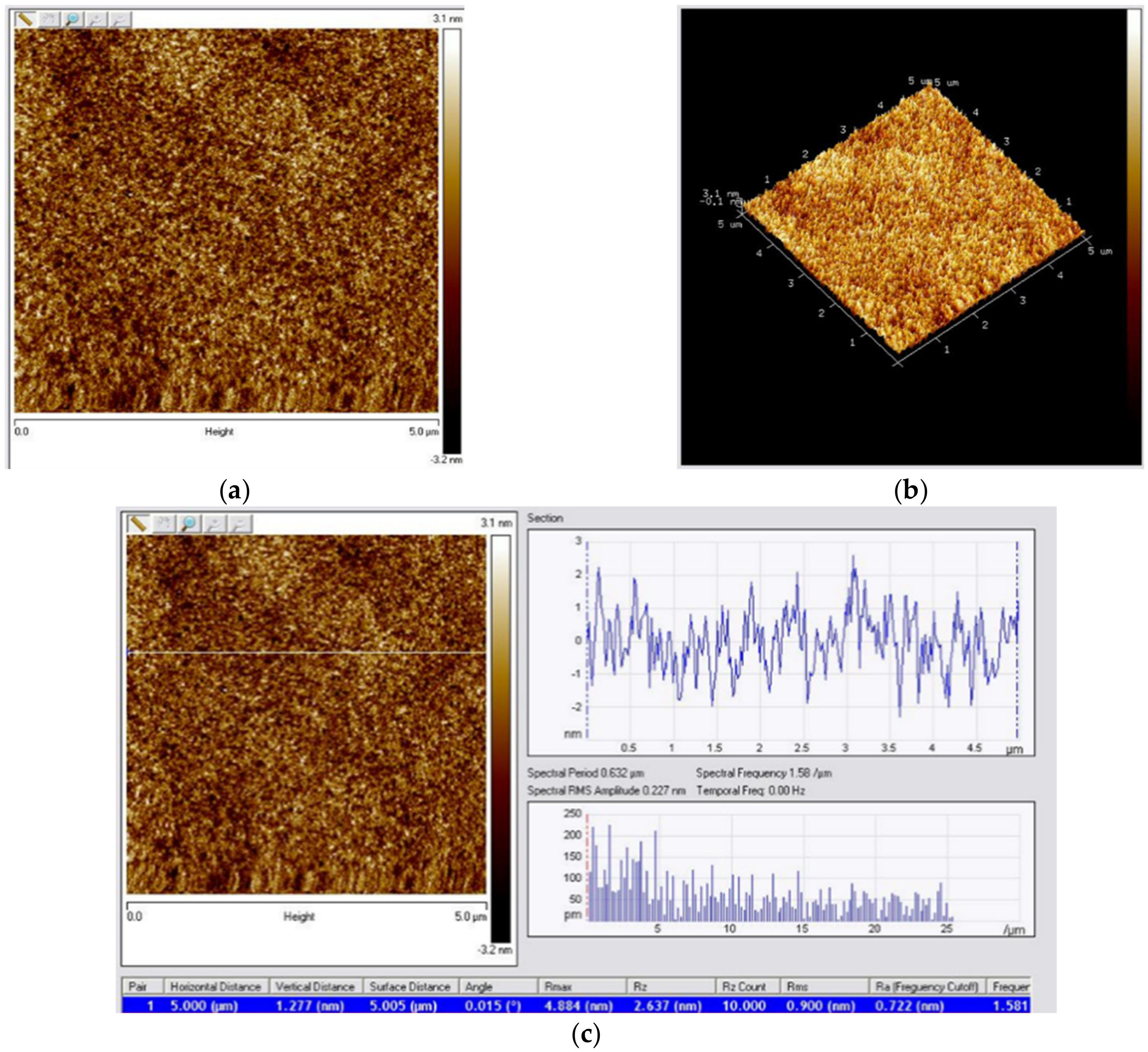
The AFM test was set to contact mode for the surface measurement of the NDG. The tip of the probe and the sample of NDG were in perpetual contact. The scanning area under investigation in this study was
. Using glass as the reference base, the surface of the NDG was measured and analyzed, as shown in
Figure 8.
Figure 8a,b show the 2D image and 3D morphology, respectively. The sectional contour of the NDG surface is shown in
Figure 8c. Different roughness measurements were calculated as shown in
Table 2, and include the vertical distance roughness, central line average roughness R
a, ten points average roughness R
z, maximum height roughness R
max, and root-mean-squared (rms) roughness R
q. As stated in [
22], R
q with an inspection area of
was used as an index for a large-area graphene to be wrinkle-free and defect-free, or not. According to the results in the study, R
q was about 3.5–4.0 nm for graphene on glass without a titanium (Ti) coating. With the glass coated with Ti in [
22], the value of R
q would decrease significantly for the graphene film, which had less wrinkles or defects. It is estimated for the results from [
22] that the value of R
q in this study was 0.9 nm, the same as that of graphene on glass with a coating thickness of Ti of about 4 nm.
4.3. Raman Analysis for NDG Powder
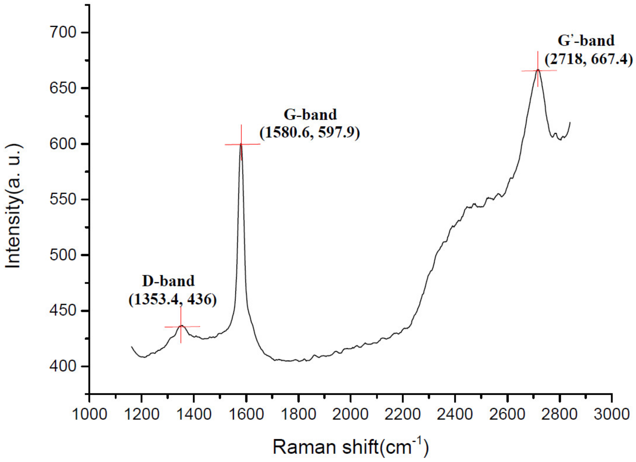
In this study, three measures with a fixed integration time of 60 s were averaged for the Raman mapping signals. As shown in
Figure 9, The peaks of the spectrum can be explained as follows. The G-band is the main characteristic peak of graphene, which is caused by the in-plane vibration of carbon atoms. The G-band of NDG in this study appeared around 1580 cm
−1. The G-band can effectively reflect the number of graphene layers and is also easily affected by doping. The D-band is generally considered to be a disordered vibration, which is used to characterize the defects or edges in graphene. The D band of NDG was located at about 1353 cm
−1. The intensity of the D-band is proportional to the defects in graphene or NDG. In the study by Palaniselvam et al. [
23], it was pointed out that the intensity ratio of the D- and G-bands (i.e., (
ID/
IG ratio) could be used to estimate the defects of NDG samples where a higher ratio produced more defects on NDG). The
ID/
IG ratio of the NDG used in [
23] was 1.02, and the corresponding result of the NDG in this study was 0.729 (436/597.9). This shows that the NDG used in this study had less defects than that of the NDG in [
23]. In 2010, the
ID/
IG ratio was studied in detail by Dressselhaus et al. [
24]. More complex formulae were developed to estimate the
ID/
IG ratio in [
24]. Related to the 2D-band, also known as the G’-band, it is a two-phonon resonance Raman peak that appears near 2718 cm
−1. The 2D-band can also be used to determine the number of layers for graphene or NDG. Compared to the result by Ferrari el al. [
25], the layer number of the NDG in this study was more than 10. Graphene with dozens of layers is sometimes called multi-layer or graphite-like graphene and the NDG used in this study belongs to the multi-layer graphene type.
4.4. Four-Point Probe Resistance Measurement for NDG Ink Coating
The four-point probe resistance measuring machine limits the size of the test specimens up to a dimension of 20 × 20 mm
2.
Figure 10 illustrates the preparation for the test specimens. The coordinate measuring machine (CMM) was used for the thickness measurement of the NDG ink coating. Half the area of the test specimen was taped to measure the NDG coating thicknesses with the variation of the spinning speeds. The results are shown in
Table 3. According to the table, the spinning speed produced a thickness of 20 μm at 100 rpm, 15 μm at 200 rpm, and 10 μm at 300 rmp, respectively. Using the thickness of the NDG paint as input data, the specimens were then tested by the resistance measuring machine. The results are shown in
Table 4. For the different thicknesses of the NDG coatings, the measuring resistances were over the upper limit of the machine,
. This shows that the electrical resistance of the NDG ink coating was high enough to be insulative.
4.5. Cross-Cut Adhesion Test for NDG Ink Coating
The aluminum plate specimen, with dimensions of 210 × 210 mm
2, was coated with the NDG ink paint with a paint thickness of 0.027 mm. The cross-cut adhesion test was performed three times on different areas of the specimen. The tooth spacing of the test knife was 1 mm. According to
Table 5 (ASTM D3359), the paint of NDG belonged to grade 4B. As shown in [
26], the corresponding pattern of 4B is shown in
Table 6.
4.6. Temperature Measurement for the Driver Board of the LED Lamp
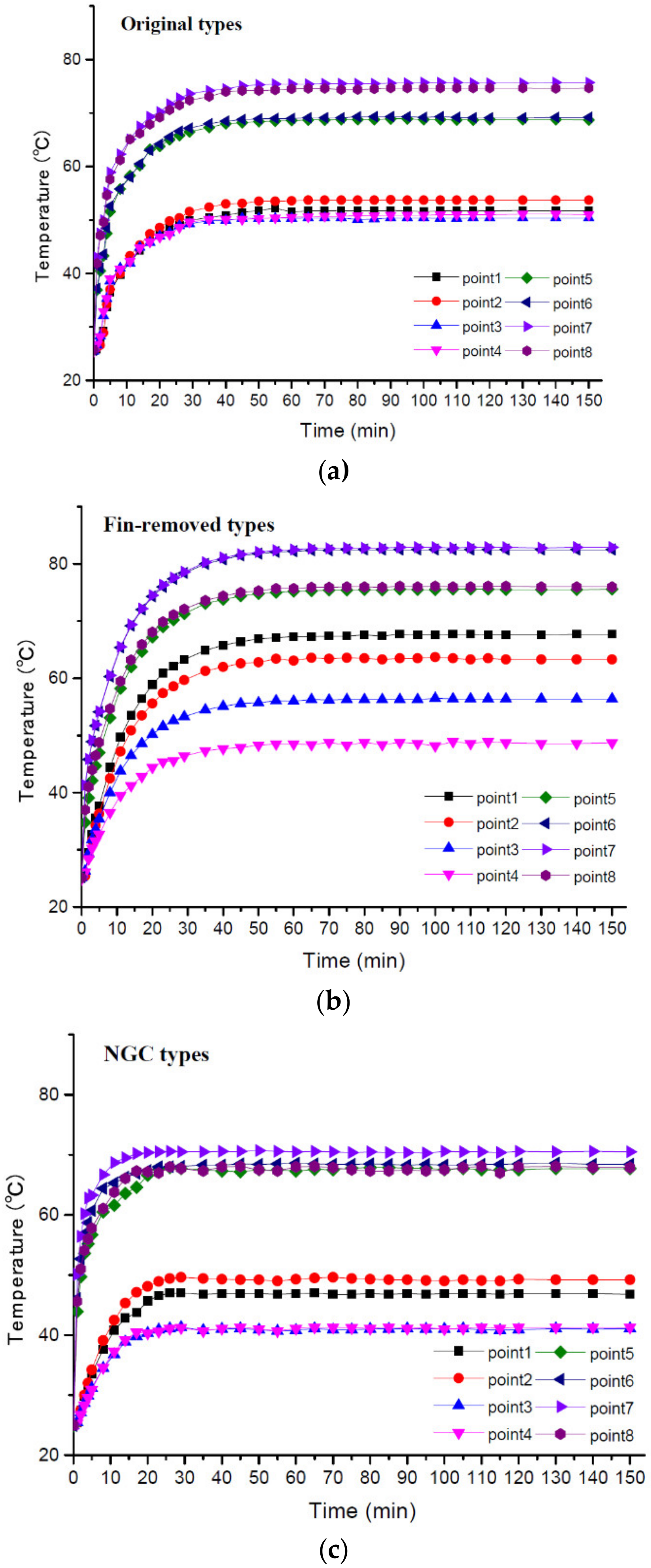
The temperature data of the LED lamps were measured and recorded by the thermocouples and DR230 data recorder. The temperature variations of the points on the printed circuited circuit board assembly (PCBA) are shown in
Figure 11.
As shown in
Figure 6, there were different types of LED lamps for the test, the original lamp, the fin-removed lamp, and the NGC lamp. The variations of temperature are shown in
Figure 11a for the original lamp,
Figure 11b for the fin-removed lamp, and
Figure 11c for the NGC lamp, respectively. It was observed that the time for the steady temperature was about 45 min for the original lamp, 60 min for the fin-removed lamp, and 25 min for the NGC lamp. The steady temperatures are listed in
Table 7 for comparison. Points 5–8 are the points for the LED chips, which are electronic elements of high power. At these points, the temperatures were higher than those of the other four points 1–4. In particular, the highest temperature was found at point 7, which was close to the live wire terminal. The temperature at point 7 was 75.7 °C for the original lamp, 85.9 °C for the fin-removed lamp, and 70.5 °C for the NGC lamp. Taking the temperature at point 7 of the fin-removed lamp as the reference temperature, the temperature drop ratio for the original lamp was about 11.9% (10.2 divided by 85.9) and represents the fin effect. Similarly, the temperature drop ratio for the NGC lamp was about 17.9% (15.4 divided by 85.9) and represents the NDG coating effect. The result shows that the NDG coating had a better temperature drop ratio than that of the original lamp with cooling fins.
4.7. Integrating Sphere Measurement for the LED Lamps
The integrating sphere was used to measure the light intensity, light efficiency, and color rendering index for the different LED lamps. The results are listed in
Table 8. The input voltage for the LED lamps was 48 V. Among the LED lamps, the NGC lamp had the highest light efficiency of 93.58 lm/W. Meanwhile, the NGC lamp had the light intensity of 781.42 lm, which was the strongest among the results for the LED lamps. The NGC lamp also had the best performance of the color rendering index at 71.4. The high light efficiency explains the excellent temperature drop ratio for the NGC lamp.
5. Conclusions
The application of the NDG ink for the thermal management of the LED lamps was studied in this paper. The NDG ink was also tested for adhesion and electrical resistance. The corresponding inspections including XPS, AFM, and Raman spectroscopy were used to investigate the characterization of the NDG powder in this study. The results can be concluded as follows:
As a result of the XPS inspection, it was found that the content of the detected nitrogen component in NDG was 3.8%.
The AFM test results for the NDG powder showed that the height of the stacked NDG layers was 1.277 nm. The roughness R
q can be an index of wrinkles and defects for the graphene film. The roughness R
q of the NDG sample in this study was 0.9 nm, the same as that of graphene on glass with a Ti coating thickness of about 4 nm in [
22].
In the Raman analysis, the intensity ratio of D and G bands (i.e., (ID/IG ratio) showed the defects of the NDG samples where a higher ratio produced more defects on NDG. The result of the NDG in this study was 0.729 (436/597.9). In addition, the NDG in this study belonged to the multi-layer graphene with a layer number over 10.
When the NDG ink was spray-baked, the cross-cut adhesion test was performed in accordance with ASTM D3359. The results showed that small pieces of peeling were found at the intersection of the cuts. The actual damage in the grid area was less than 5%, which was judged to be class 4B for the NDG, according to ASTM D3359.
In the four-point probe resistance experiment, the NDG ink had a high electrical resistance, and its volumetric resistance was greater than 109 Ω-cm, which was in the range of an insulator. This proved that the NDG ink was suitable for the LED lamp coating, which is required to have high electrical resistance.
According to the PCBA temperature measurements, the results showed that the performance of the NGC lamp was the best among the tested LED lamps. Compared to the fin-removed LED lamp, the temperature drop ratio was 17.9% for the NGC lamp and 11.9% for the original lamp (heat transfer enhancement with fins).
In the integrating sphere experiment, compared to the original lamp with the luminous efficiency of 90.29 lm/W, the NGC lamp improved the effective luminous efficiency with a value of 93.58 lm/W.
Author Contributions
Conceptualization: A.-D.L., W.-K.Y. and C.-M.H.; Data curation: A.-D.L., W.-K.Y. and S.Z.P.; Formal analysis: A.-D.L. and W.-K.Y.; Funding acquisition: A.-D.L., C.-Y.C. and C.-M.H.; Investigation: A.-D.L., W.-K.Y. and C.-M.H.; Methodology: A.-D.L. and W.-K.Y.; Project administration: A.-D.L., W.-K.Y., S.Z.P., C.-Y.C. and C.-M.H.; Resources: A.-D.L.; Software: W.-K.Y.; Supervision: A.-D.L., W.-K.Y., S.Z.P. and C.-Y.C.; Validation: W.-K.Y.; Writing—original draft: A.-D.L. and W.-K.Y.; Writing—review & editing: A.-D.L., W.-K.Y., S.Z.P., C.-Y.C. and C.-M.H. All authors have read and agreed to the published version of the manuscript.
Funding
This research received no external funding.
Conflicts of Interest
The authors declare no conflict of interest.
References
- Novoselov, K.S.; Geim, A.K.; Morozov, S.V.; Jiang, D.; Zhang, Y.; Dubonos, S.V.; Grigorieva, I.V.; Firsov, A.A. Electric field effect in atomically thin carbon films. Science 2004, 306, 666–669. [Google Scholar] [CrossRef]
- Ramanathan, T.; Abdala, A.A.; Stankovich, S.; Dikin, D.A.; Herrera-Alonso, M.; Piner, R.D.; Schniepp, H.C.; Chen, X.; Ruoff, R.S.; Nguyen, S.T.; et al. Functionalized graphene sheets for polymer nanocomposites. Nat. Nanotechnol. 2008, 3, 327–331. [Google Scholar] [CrossRef]
- Giovannetti, G.; Khomyakov, P.A.; Brocks, G.; Karpan, V.M.; van den Brink, J.; Kelly, P.J. Doping graphene with metal contacts. Phys. Rev. Lett. 2008, 101, 026803. [Google Scholar] [CrossRef]
- Wei, D.; Liu, Y.; Wang, Y.; Zhang, H.; Huang, L.; Yu, G. Synthesis of N-Doped Graphene by Chemical Vapor Deposition and Its Electrical Properties. Nano Lett. 2009, 9, 1752–1758. [Google Scholar] [CrossRef]
- Ren, P. Fabrication of nitrogen-doped graphenes by pulsed laser deposition and improved chemical enhancement for Raman spectroscopy. Mater. Lett. 2017, 216, 37. [Google Scholar] [CrossRef]
- Allen, M.J.; Tung, V.C.; Kaner, R.B. Honeycomb Carbon: A Review of Graphene. Chem. Rev. 2010, 110, 132–145. [Google Scholar] [CrossRef] [PubMed]
- Kim, K.K.; Reina, A.; Shi, Y.; Park, H.; Li, L.-J.; Lee, Y.H.; Kong, J. Enhancing the conductivity of transparent graphene films via doping. Nanotechnology 2010, 21, 28. [Google Scholar] [CrossRef] [PubMed]
- Fujita, J.-I.; Hiyama, T.; Hirukawa, A.; Kondo, T.; Nakamura, J.; Ito, S.-I.; Araki1, R.; Ito, Y.; Takeguchi, M.; Pai, W.W. Near room temperature chemical vapor deposition of graphene with diluted methane and molten gallium catalyst. Sci. Rep. 2017, 7, 12371. [Google Scholar] [CrossRef]
- Hernandez, Y.; Nicolosi, V.; Lotya, M.; Blighe, F.M.; Sun, Z.; De, S.; McGovern, I.T.; Holland, B.; Byrne, M.; Gun’ko, Y.; et al. High yield production of graphene by liquid phase exfoliation of graphite. Nat. Nanotechnol. 2008, 3, 563–568. [Google Scholar] [CrossRef]
- Goharshadi, G.K.; Mahdizadeh, S.J. Thermal conductivity and heat transfer properties of nitrogen-doped graphene. J. Mol. Graph. Model. 2015, 62, 74–80. [Google Scholar] [CrossRef]
- Lin, Y.-C.; Lin, C.-Y.; Chiu, P.-W. Controllable graphene N-doping with ammonia plasma. Appl. Phys. Lett. 2010, 96, 133100. [Google Scholar] [CrossRef]
- Liang, T.; Wang, C.; Jiang, Z. Preparation and Characterization of Polysiloxane/Graphene Heat Conducting and Dissipating Coating. Paint. Coat. Ind. 2017, 49, 7–10. [Google Scholar]
- Costa, M.A.D.; Costa, G.H.; dos Santos, A.S.; Schuch, L.; Pinheiro, J.R. A high efficiency autonomous street lighting system based on solar energy and LEDs. In Proceedings of the 2009 Brazilian Power Electronics Conference, Bonito-Mato Grosso do Sul, Brazil, 27 September–1 October 2009; pp. 265–273. [Google Scholar]
- Schirripa Spagnolo, G.; Leccese, F.; Leccisi, M. LED as Transmitter and Receiver of Light: A Simple Tool to Demonstration Photoelectric Effect. Crystals 2019, 9, 531. [Google Scholar] [CrossRef]
- Huber, Rainer Thermal Management of LED Technology in Applications. LED Therm. Manag. 2007, 04, 22–27.
- Perpiñà, X.; Werkhoven, R.; Jakovenko, J.; Formánek, J.; Vellvehi, M.; Jordà, X.; Kunen, J.; Bancken, P.; Bolt, P.J. Design for reliability of solid state lighting systems. Microelectron. Reliab. 2012, 52, 2294–2300. [Google Scholar] [CrossRef]
- Raccichini, R.; Varzi, A.; Passerini, S.; Scrosati, B. The role of graphene for electrochemical energy storage. Nat. Mater. 2015, 14, 271–279. [Google Scholar] [CrossRef] [PubMed]
- Raypah, M.E.; Dheepan, M.K.; Devarajan, M.; Sulaiman, F. Investigation on thermal characterization of low power SMD LED mounted on different substrate packages. Appl. Therm. Eng. 2016, 101, 19–29. [Google Scholar] [CrossRef]
- Zhang, Y.; Zhang, M. Behavior of a graphene/epoxy composite used as thermal interface material for LED heat dissipation. Mater. Test. 2017, 59, 1037–1042. [Google Scholar] [CrossRef]
- Kantharaj, R. Thermal conduction in graphite flake-epoxy composites using infrared microscopy. In Proceedings of the 16th IEEE Intersociety Conference on Thermal and Thermomechanical Phenomena in Electronic Systems (ITherm), Orlando, FL, USA, 30 May–2 June 2017; pp. 1–7. [Google Scholar]
- Wang, Y.-M. Investigation of Annealing Effects on PEDOT: PSS and P3HT: PCBM Films by Micro-Raman Spectroscopy. Master’s Thesis, National Kaohsiung University of Applied Sciences, Kaohsiung, Taiwan, 2009. (In English). [Google Scholar]
- Park, B.-J.; Choi, J.-S.; Kim, H.-S.; Kim, H.-Y.; Jeong, J.-R.; Choi, H.-J.; Jung, H.-J.; Jung, M.-W.; An, K.-S.; Yoon, S.-G. Realization of large-area wrinkle-free monolayer graphene films transferred to functional substrates. Sci. Rep. 2015. [Google Scholar] [CrossRef]
- Palaniselvam, T.; Aiyppa, B.H.; Kurungot, S. An efficient oxygen reduction electrocatalyst from graphene by simultaneously generating pores and nitrogen doped active sites. J. Mater. Chem. 2012, 22, 23799–23805. [Google Scholar] [CrossRef]
- Dresselhaus, M.S.; Jorio, A.; Filho, A.G. Souza Defect characterization in graphene and carbon nanotubes using Raman spectroscopy. Philos. Trans. R. Soc. 2010, 368, 5355–5377. [Google Scholar] [CrossRef] [PubMed]
- Ferrari, A.C.; Meyer, J.C.; Scardaci, V.; Casiraghi, C.; Lazzeri, M.; Mauri, F.; Piscanec, S.; Jiang, D. Raman spectrum of graphene and graphene layers. Phys. Rev. Lett. 2006, 97, 187401. [Google Scholar] [CrossRef] [PubMed]
- Milionis, A.; Loth, E.; Bayer, I.S. Recent advances in the mechanical durability of superhydrophobic materials. Adv. Colloid Interface Sci. 2016, 229, 57–79. [Google Scholar] [CrossRef] [PubMed]
Figure 1.
Light-emitting diode (LED) lamp.
Figure 1.
Light-emitting diode (LED) lamp.
Figure 2.
Systematic Illustration for the integrating sphere.
Figure 2.
Systematic Illustration for the integrating sphere.
Figure 3.
Integrating sphere.
Figure 3.
Integrating sphere.
Figure 4.
Hybrid recorder DR230.
Figure 4.
Hybrid recorder DR230.
Figure 5.
Layout of the monitoring points.
Figure 5.
Layout of the monitoring points.
Figure 6.
Different types of the LED lamps. (a) Original lamp, (b) Fin-removed lamp, (c) NGC lamp
Figure 6.
Different types of the LED lamps. (a) Original lamp, (b) Fin-removed lamp, (c) NGC lamp
Figure 7.
XPS analysis for NDG.
Figure 7.
XPS analysis for NDG.
Figure 8.
AFM inspection for NDG. (a) 2D image for NDG powder. (b) 3D morphology for NDG powder. (c) Roughness measurement for NDG powder.
Figure 8.
AFM inspection for NDG. (a) 2D image for NDG powder. (b) 3D morphology for NDG powder. (c) Roughness measurement for NDG powder.
Figure 9.
Raman spectrum for NDG.
Figure 9.
Raman spectrum for NDG.
Figure 10.
Test specimen preparation for the resistance measurements.
Figure 10.
Test specimen preparation for the resistance measurements.
Figure 11.
Variation of temperature for the different LED lamps. (a) Variation of temperature for points 1–8 of the original lamp. (b) Variation of temperature of points 1–8 for the fin-removed lamp. (c) Variation of temperature for points 1–8 of the NGC lamp.
Figure 11.
Variation of temperature for the different LED lamps. (a) Variation of temperature for points 1–8 of the original lamp. (b) Variation of temperature of points 1–8 for the fin-removed lamp. (c) Variation of temperature for points 1–8 of the NGC lamp.
Table 1.
Chemical composition of the nitrogen-doped graphene (NDG).
Table 1.
Chemical composition of the nitrogen-doped graphene (NDG).
| Core-Line | Atomic % |
|---|
| C 1S | 85.8 |
| O 1S | 10.4 |
| N 1S | 3.8 |
Table 2.
Roughness measurement results.
Table 2.
Roughness measurement results.
| Vertical Distance: 1.277 (nm) |
|---|
| Roughness | Value |
|---|
| Rmax | 4.884 (nm) |
| Rz | 2.637 (nm) |
| Rq | 0.900 (nm) |
| Ra | 0.722 (nm) |
Table 3.
Variation of the coating thickness with the spinning speed.
Table 3.
Variation of the coating thickness with the spinning speed.
| Revolving Speed | Thickness (μm) |
|---|
| 100 rpm | 20 |
| 200 rpm | 15 |
| 300 rpm | 10 |
Table 4.
Electrical properties for the NDG coatings.
Table 4.
Electrical properties for the NDG coatings.
| Thickness (μm) | 20 | 15 | 10 |
|---|
| Resistance (Ω) | > 1.21037 | > 1.2 × 1037 | > 1.2 × 1037 |
| Sheet Resistance (Ω/) | 5.06 × 1037 | 5.06 × 1037 | 6.04 × 1037 |
| Volume Resistivity (Ω-cm) | | | |
| Conductivity (Siemens/cm) | 9.81 × 10−36 | 1.31 × 10⁻³⁵ | 1.65 × 10−39 |
Table 5.
ASTM D3359 standard.
Table 5.
ASTM D3359 standard.
| Classification | Surface of Cross-Cut Area from Which Flaking Has Occurred |
|---|
| 5B | The edges of the cuts are completely smooth; none of the squares of the lattice is detached. |
| 4B | Small flakes of the coating are detached at intersections; less than 5% of the area is affected. |
| 3B | Small flakes of the coating are detached along edges and at intersections of cuts. The area affected is 5 to 15% of the lattice. |
| 2B | The coating has flaked along the edges and on parts of the squares. The area affected is 15 to 35% of the lattice. |
| 1B | The coating has flaked along the edges of cuts in large ribbons and whole squares have detached. The area affected is 35 to 65% of the lattice 35%~65% |
| 0B | Flaking and detachment worse than Grade 1. |
Table 6.
Test patterns for the ASTM D3359 standard.
Table 7.
Stable temperature distribution for the different LED lamps (Unit: °C).
Table 7.
Stable temperature distribution for the different LED lamps (Unit: °C).
| Point | Original Lamp | Fin-Removed Lamp | NGC Lamp |
|---|
| 1 | 52.2 | 67.7 | 47 |
| 2 | 53.8 | 63.7 | 49.6 |
| 3 | 50.4 | 69.1 | 50.5 |
| 4 | 51.1 | 65.7 | 52.2 |
| 5 | 68.9 | 75.6 | 67.9 |
| 6 | 69.3 | 82.5 | 68.6 |
| 7 | 75.7 | 85.9 | 70.7 |
| 8 | 74.7 | 76.1 | 68.1 |
Table 8.
Properties for the different LED types.
Table 8.
Properties for the different LED types.
| Lamp Type | Original | Fin-Removed | NGC |
|---|
| Power (W) | 8.35 | 8.35 | 8.35 |
| Lumen (lm) | 753.99 | 717.02 | 781.42 |
| Light efficiency (lm/W) | 90.29 | 85.87 | 93.58 |
| Color rendering Index | 69.7 | 70.6 | 71.4 |
© 2020 by the authors. Licensee MDPI, Basel, Switzerland. This article is an open access article distributed under the terms and conditions of the Creative Commons Attribution (CC BY) license (http://creativecommons.org/licenses/by/4.0/).


