Article

An Evidence Basis for Future Equestrian Helmet Lateral Crush Certification Tests

1
School of Mechanical & Materials Engineering, University College Dublin, Belfield, 4 Dublin, Ireland
2
COMFG Ltd. (Charles Owen), Royal Works, Croesfoel Ind. Park, Wrexham LL14 4BJ, UK
3
R&D Consulting Engineers Ltd., Leeds LS17 6AF, UK
4
Vector Scientific Inc., Golden, CO 80403, USA
5
School of Veterinary Medicine, University College Dublin, Belfield, 4 Dublin, Ireland
*
Author to whom correspondence should be addressed.
Appl. Sci. 2020, 10(7), 2623; https://doi.org/10.3390/app10072623
Submission received: 20 March 2020 / Revised: 2 April 2020 / Accepted: 3 April 2020 / Published: 10 April 2020
(This article belongs to the Special Issue Applied Biomechanics in Sport, Rehabilitation and Ergonomy)

Abstract

:
The aim of this study is to determine what loads are likely to be applied to the head in the event of a horse falling onto it and to determine by how much a typical equestrian helmet reduces these loads. An instrumented headform was designed and built to measure applied dynamic loads from a falling horse. Two differently weighted equine cadavers were then dropped repeatedly from a height of 1 m (theoretical impact velocity of 4.43 m/s) onto both the un-helmeted and helmeted instrumented headforms to collect primary force–time history data. The highest mean peak loads applied to the headform by the lighter horse were measured at the bony sacral impact location (15.57 kN ± 1.11 SD). The lowest mean peak loads were measured at the relatively fleshier right hind quarter (7.91 kN ± 1.84 SD). For the heavier horse, highest mean peak loads applied to the headform were measured at the same bony sacral impact location (16.02 kN ± 0.83 SD), whilst lowest mean peak loads were measured at the more compliant left hind quarter (10.47 kN ± 1.08 SD). When compared with the un-helmeted mean values, a reduction of 29.7% was recorded for the sacral impact location and a reduction of 43.3% for the lumbosacral junction location for helmeted tests. Notably, all measured loads were within or exceeded the range of published data for the fracture of the adult lateral skull bone. Current helmet certification tests are not biofidelic and inadequately represent the loading conditions of real-world “lateral crush” accidents sustained in equestrian sports. This work presents the first ever evidence basis upon which any future changes to a certification standards test method might be established, thereby ensuring that such a test would be both useful, biofidelic, and could ensure the desired safety outcome.

1. Introduction

Equestrian helmet certification tests are designed to ensure that a minimum performance and quality level is achieved in terms of helmet crashworthiness and structural integrity. As equestrian sports are high risk [1,2,3,4,5], with the primary type of accident involving a fall from the horse resulting in a head impact [6], it makes good sense that the main helmet functional test in the standards involves recreating some simplified impact conditions [7,8,9]. The next most significant test in most equestrian helmet standards is referred to as the lateral crush test, also referred to as the lateral deformation test or rigidity test. However, unlike impact tests, the origins of which are well documented in the literature [10,11], the rationale and evidence basis for the crush test are unclear. Essentially, this particular test is formulated as a quasi-static test to represent a horse dynamically falling against or rolling over the head of a helmeted jockey.
The lateral crush test itself is relatively simple. A helmet is placed between two metal plates and is crushed quasi-statically until a peak force is reached at a specified loading rate (see Figure 1). There is no headform in the helmet. To pass the test, maximum and residual crush limits must not be exceeded. Peak loads are set to be 800 N for both PAS 015 [9] and EN 1384 [8] and 1000 N for the Snell E2016 standard [12]. In all cases, the maximum permitted crush is 30 mm and the residual crush may not exceed 10 mm.
In discussions with engineers working within the standards industry and with standards committee members, it is understood that the lateral crush tests are used to ensure that the helmet is ‘not too soft’ and that the structure of the helmet has some ‘stabilizing effect’. It is not intended to simulate a real-world accident. However, there has been no quantification of what constitutes a helmet that is ‘too soft’, particularly if its impact performance is sufficient. Additionally, in discussions with the equestrian community, it is clear that the lateral crush test is believed to represent a horse falling onto a helmet. Indeed, the most recent revision of the EN1384 standard was to increase the peak force that could be sustained from 630 N to 800 N. That decision was taken on the basis that it should improve helmet performance in the event of a horse falling onto a rider’s head. However, there is no evidence that this change would have any influence on helmet performance.
Equestrians have a high risk of head injury [13] and the majority of professional jockey fatalities are as a result of head injury sustained from a fall. Additionally, reported rates of concussion or mild traumatic brain injury (mTBI) are higher for equestrians than those in boxing and American football [6]. However, when compared with the number of falls and head impacts, crush injuries, particularly to the head, appear to be rare with few reported in the literature [14]. Nevertheless, in some situations such as cross-country riding or eventing, a horse can somersault during a jump and land on the rider. In such cases the injuries can be catastrophic and sometimes fatal [14]. There may be merit in introducing a more realistic crush test to the standards if the objective of the test is to improve helmet performance while being dynamically crushed. However, there are no primary empirical data on which to base such a test. It is not known what typical loads are applied to the rider’s head during such an accident and it is not known by how much a typical equestrian helmet might reduce these loads.
The aim of this present paper is to address this deficit directly by determining what loads are likely to be applied to the rider’s head in the event of a horse falling onto it, and to investigate the extent to which a typical equestrian helmet reduces these loads. It is hoped that these primary data will help to inform and create an evidence basis for future standard lateral crush tests.

2. Materials and Methods

This study has two main parts. First, an instrumented headform was designed and built to measure applied dynamic loads from a falling horse. Second, equine cadavers were dropped onto both un-helmeted and helmeted instrumented headforms and the associated force–time history data were collected.

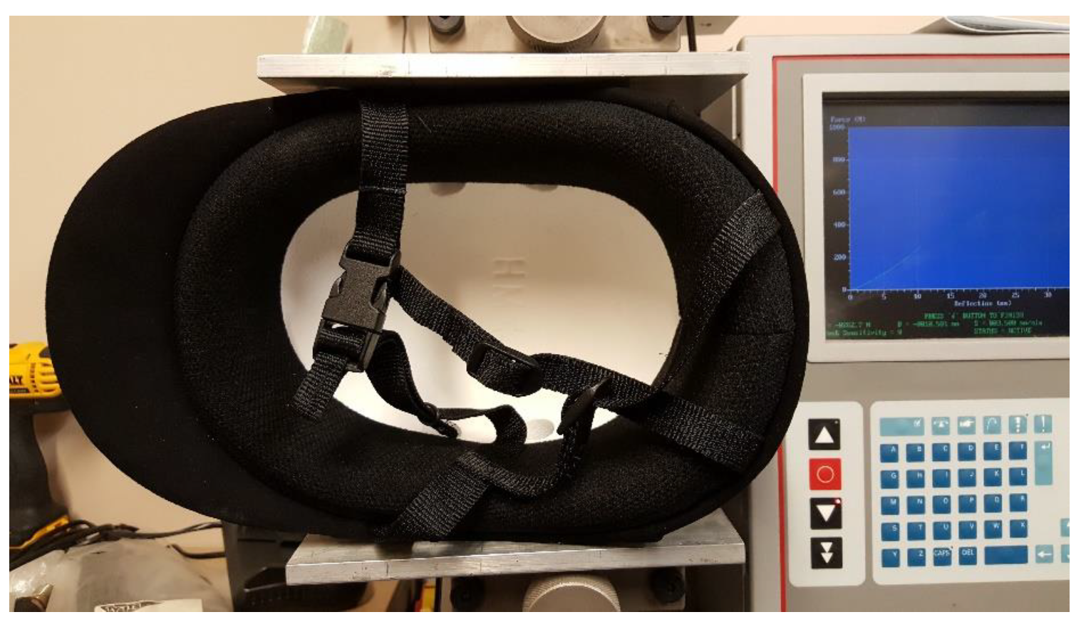
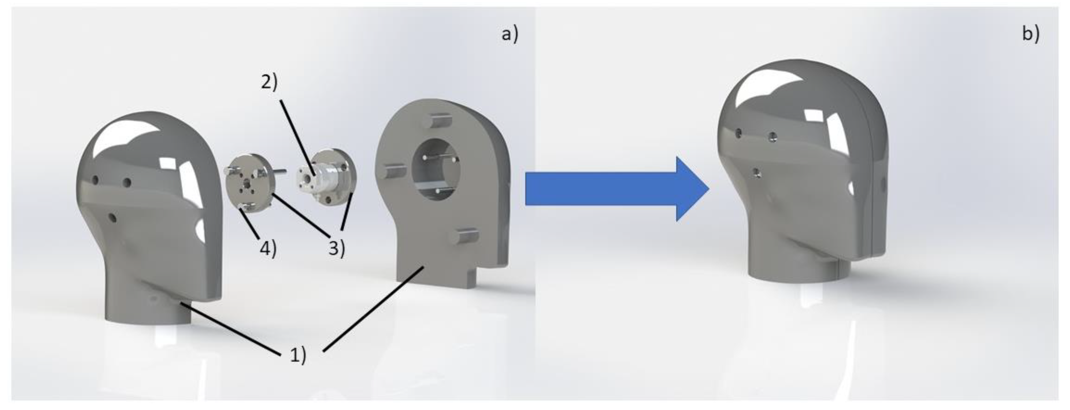
2.1. Instrumented Headform

To measure the lateral forces applied by the falling horse, the external geometry of the EN960:2006 standard headform was used to create a CAD model (see Figure 2). The headform was modelled on size J (the average male). A Makerbot Z18 3D printer was used to physically print the headform from this CAD model, similar to [15]. To make the printed poly-lactic-acid (PLA) size J headform, Monsterfil 1.75 mm PLA filament was printed at 100% density in 0.2 mm layers. The print had a two-shell outer surface and a linear infill. The headform was fitted with a Kistler uniaxial load cell rated to 70 kN and data acquisition was by means of a Kistler single channel laboratory amplifier. Data were filtered to ISO 6487 [16].

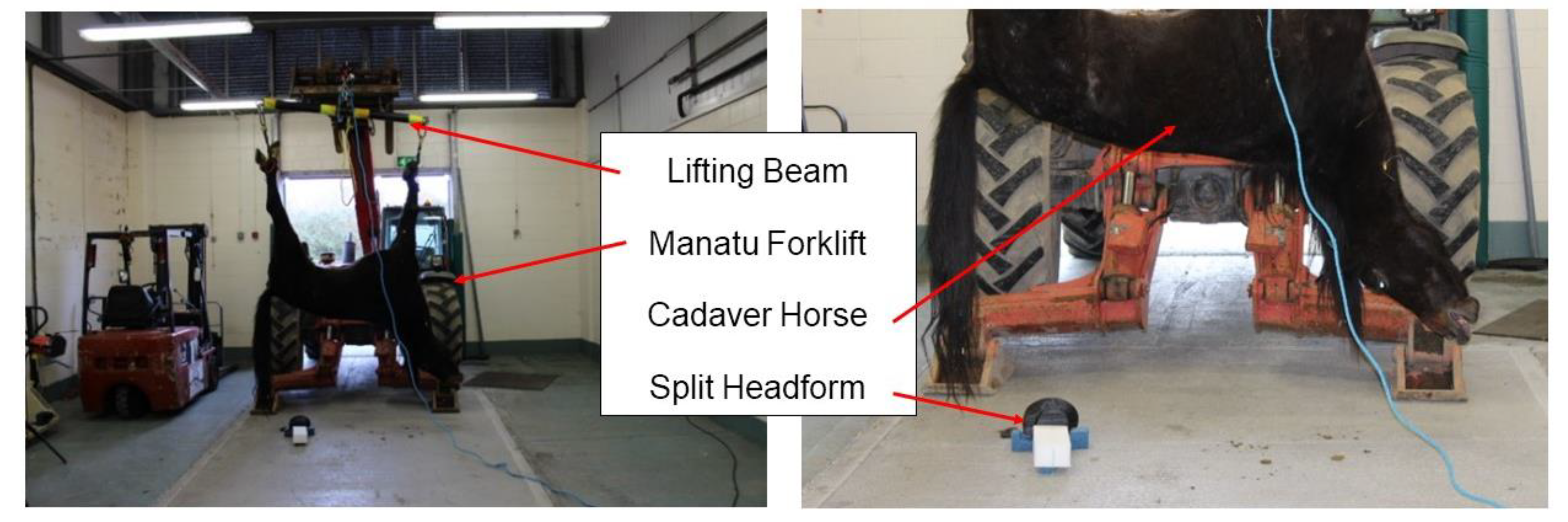
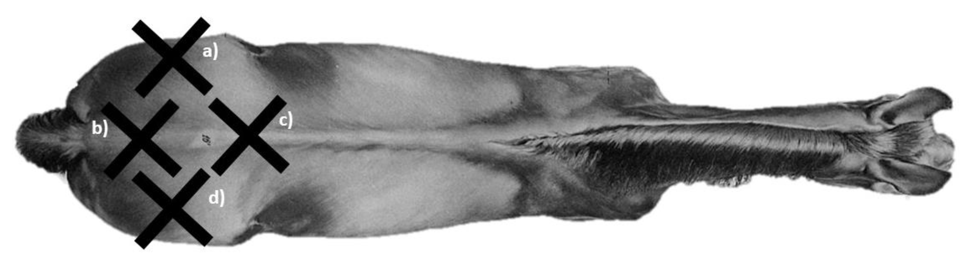
2.2. Equine Cadaver Drop Tests

For the drop tests, two fresh equine cadavers were used, one 343 kg female (horse 1) and one 370 kg male (horse 2). Both animals had been euthanised for reasons unrelated to the present study on the day of testing. Full ethical exemption was approved (AREC-E-17-09).
The equine cadavers were dropped from a height of 1.2 m onto the instrumented J headform which was positioned on a rigid concrete surface. The drop height was chosen following analysis of real-world equestrian accident video footage, such as described by Connor et al., [13] and Clark et al., [17]. The concrete surface had been chosen as it was essentially rigid and served to eliminate surface variability.
A Manatu forklift and lifting beam was used to lift the cadavers to the drop height (see Figure 3). A quick release hook clamp was used to drop the cadaver. For the un-helmeted tests, four impact locations were chosen on each horse, the left hind quarter, the right hind quarter, lumbosacral vertebrae, and the sacral vertebrae (see Figure 4). These impact locations were chosen based on the analysis of video footage of horse falls and they also represented the largest area of the animal that is not covered by a saddle, apart from the head and neck. For each horse, 3 drops were carried out per impact location. The helmet model used was a commonly available 57 cm jockey style equestrian helmet, certified to ASTM F1163-15 [7], EN 1384 [8] and PAS015 [9]. and Ideally, other equestrian helmet models would also have been tested. However, due to availability and price constraints, this common and widely used helmet model was chosen as a good representative of commercially available helmets for the 50th percentile male sized head. Helmeted tests were carried out on the lumbosacral vertebrae junction and the sacral vertebrae locations, as these were found to be the most stable locations in terms of drop test repeatability. Additionally, only the heavier male animal was used for the helmeted tests, as the number of helmets available was limited to six. The force–time data were recorded for each drop test. In total, 30 drop tests were carried out: 24 un-helmeted tests and 6 helmeted tests. Means and standard deviations were calculated for repeated tests at each impact location and for all impact locations combined. Peak load data were analysed statistically using a one-way ANOVA with post-hoc t-tests (α = 0.05) between helmeted and un-helmeted tests and between impact locations to determine statistically significant differences.

3. Results

Force–time data were successfully collected for all 30 drop tests with the split headform proving to be reliable and repeatable.

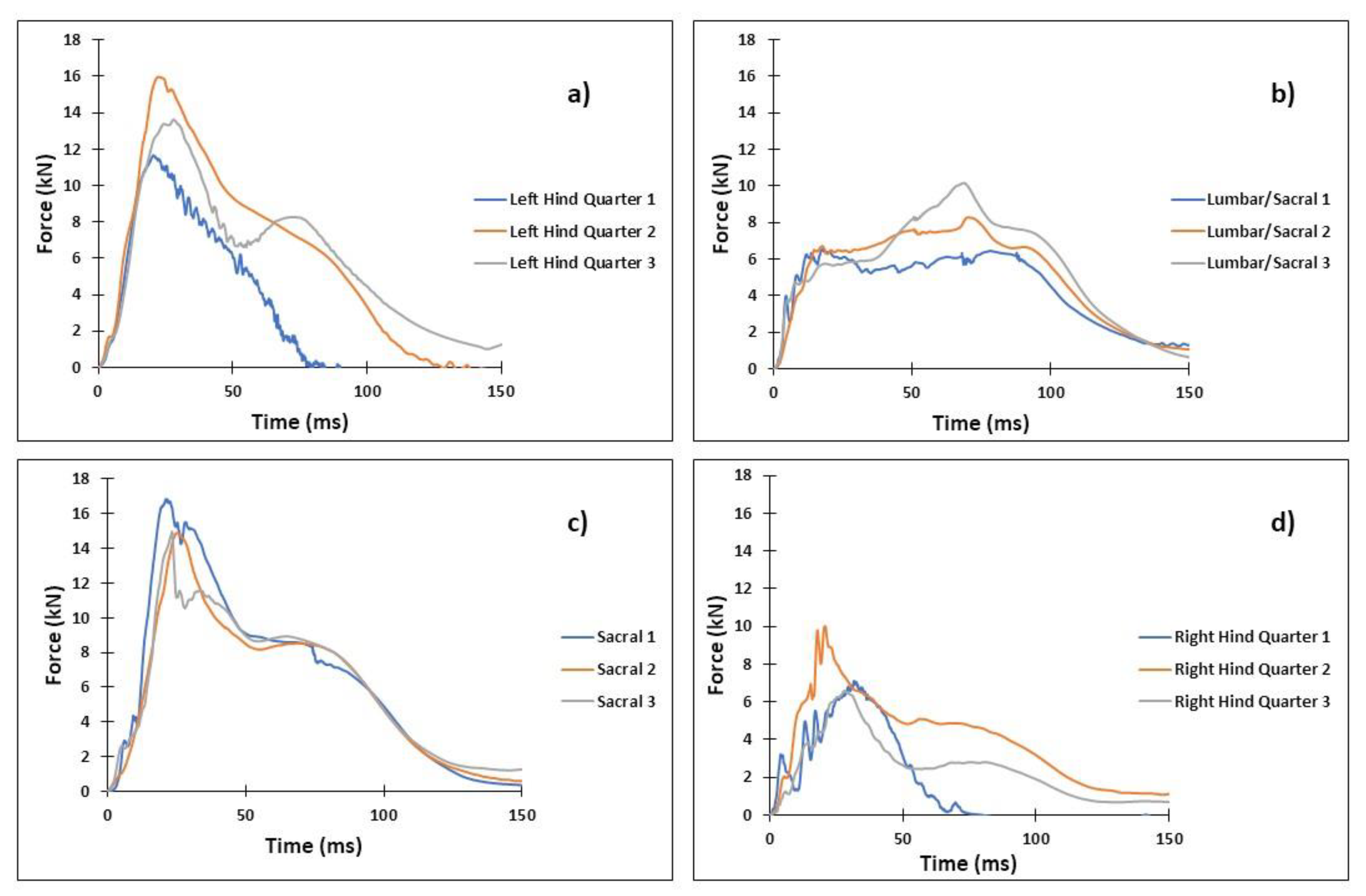
3.1. Horse 1 Drop Tests

Horse 1 was the lighter of the two horses, weighting 343 kg. The most repeatable data were collected from the lumbosacral junction and sacral vertebrae impact locations (see Figure 5b,c). Both left and right hind quarter locations were less reliable as the headform was pushed out of position in some impacts (see Figure 5a,d). The highest mean peak loads applied to the headform were measured at the sacral impact location (15.57 kN). The lowest mean peak loads were measured at the right hind quarter (7.91 kN).
Table 1 below summarises the peak force for each test, time to peak load for each test, means and standard deviations for each impact location, and means and standard deviations for all impact locations on horse 1. Time to peak load is presented, as this is within the dynamic loading phase of the impact. At some stage the load transitions from being dynamic to essentially static and so it is difficult to determine the full dynamic duration of the impact. The highest mean peak loads applied to the headform by horse 1 were measured at the sacral impact location (15.57 kN ± 1.11 SD). The lowest mean peak loads were measured at the right hind quarter (7.91 kN ± 1.84 SD).

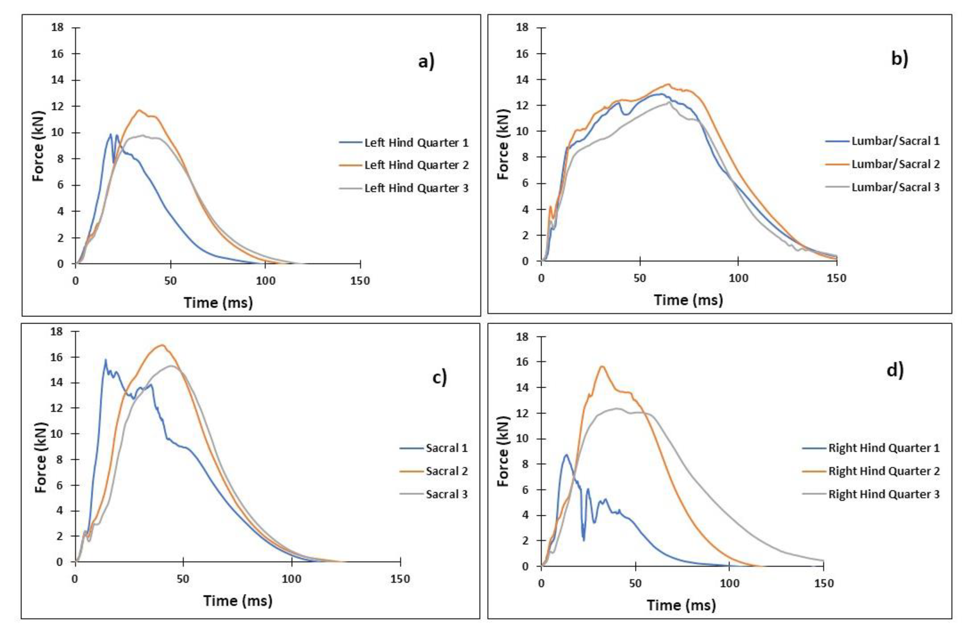
3.2. Horse 2 Drop Tests

Horse 2 was the heavier horse, weighting 370 kg. Again, the most repeatable data were collected from the lumbosacral junction and sacral vertebrae impact locations (see Figure 6b,c). However, left hind quarter data also showed good repeatability (see Figure 6a). The highest mean peak loads applied to the headform were measured at the sacral impact location (16.02 kN). The lowest mean peak loads were measured at the left hind quarter (10.47 kN). Overall, mean peak loads for all impact locations were 1.52 kN greater (11.8%) for horse 2 impacts compared with horse 1 impacts.
Table 2 below shows peak force for each test, time to peak load for each test, means and standard deviations for each impact location, and means and standard deviations for all impact locations on horse 2.

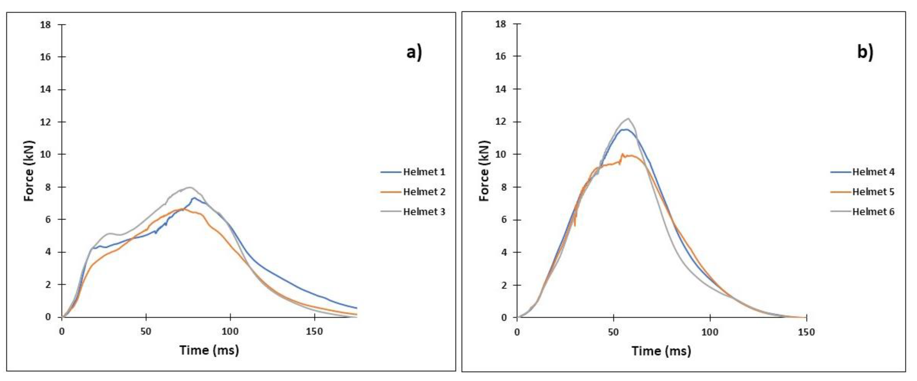
3.3. Horse 2 Helmeted Drop Tests

Figure 7 shows that the helmeted tests were more repeatable in general when compared to the un-helmeted tests, with good agreement between each test. As with the un-helmeted impacts, the sacral impact location transferred the highest peak loads to the headform, with a mean of 11.26 kN, although hind quarter locations were not tested in this case. Table 3 below shows the peak force for each test, the time to peak load for each test, as well as the means and standard deviations for each impact location and means and standard deviations for all impact locations on horse 2 (helmeted tests).

3.4. Helmeted vs. Un-helmeted vs. Impact Location

Table 4 and Table 5 below show statistical comparison results of both un-helmeted and helmeted impacts and pooled data comparisons for all impact locations.

4. Discussion

4.1. Horse Impact Data

This study successfully collected quantitative force data from a horse falling onto a surrogate headform. To the best of the authors’ knowledge, this is the first time that such data has been collected and presented. In general, the repeatability of the force–time curves is good, despite movement of the headform in some cases. Similarities in the shape of the loading curves can be seen for each impact location and standard deviations about the mean values are small. Statistically significant differences (p < 0.05) in peak loads were observed between the left hind quarter and sacral vertebrae, the lumbosacral junction and the sacral vertebrae, and between the sacral vertebrae and the right hind quarter (see Table 5).
The sacral vertebrae impact location applied the highest peak loads to the headform in all cases. This is likely due to the stiff, bony nature of this location with minimal soft tissue covering. Additionally, the location is at the centre of the animal and, during the impact, there was minimal movement of the headform, which ensured that it properly registered most of the associated load.
Quite the opposite was true of the hind quarter impact locations. There was much less headform stability here as initial contact between the horse and the headform could cause the headform to be pushed away from the horse. The lumbosacral junction vertebrae impact location proved to be very stable and shows a very different loading curve when compared to the other impact locations. A steep initial rise is followed by a much smaller slope, and in some cases a plateau. Due to the nature of this location, this two-stage loading phase occurs when the initial contact between the horse and the headform is first made and then, as the impact continues, the front and rear of the animal come into contact with the ground, effectively reducing the effective mass applied to the headform. Additionally, during each impact, the horse rotated as the legs came to rest on the concrete floor. It is possible that the rotation of the animal caused some additional instability of the headform.
Horse mass appears to be a factor. A 7.3% increase in the mass of the falling horse resulted in, on average, an 11.8% increase in the peak load applied to the headform. The horses used in this study were not large and would typically fall into the pony category [18]. Much heavier animals are ridden by equestrians and most sport horses weigh around 500–600 kg. A similar drop test with an animal of such a larger mass would result in a significant increase in loads applied to the headform.

4.2. Helmet Effects

Helmeted drop tests were only carried out on the sacral and lumbosacral junction vertebrae impact locations. Statistically significant differences (p < 0.05) were observed between helmeted and un-helmeted impacts for both impact locations (see Table 4). When compared with the un-helmeted mean values for these locations, a reduction of 29.7% can be seen for the sacral impact location and 43.3% for the lumbosacral junction location. The helmet significantly reduces peak loads applied to the headform. However, mean peak loads at the sacral and lumbosacral junction impact locations are still high at 11.26 kN and 9.29 kN, respectively.

4.3. Skull Fracture

Force levels required for lateral skull fracture vary significantly. Mean values reported in the literature range from 3.5 kN to 12.4 kN [19,20,21,22,23,24,25]. However, these forces vary with the surface area of the impactor and the impact velocity [20]. It should also be noted that skull fracture occurs at much lower loads for children [26]. Regardless, the measured loads in every test presented in this study fall within or exceed this range. This includes the helmeted tests. Although the helmet can significantly reduce the load applied to the head, it cannot protect against skull fractures in a severe scenario such as this. However, this type of dynamic loading could be seen as an extreme case and it is quite possible that the helmet would provide significant protection in cases where the horse merely rolls onto the head rather than falls onto it. More research is required to determine if this is the case for such a quasi-static loading scenario.

4.4. Limitations

The headform used was instrumented with a uniaxial load cell. This was chosen as a robust solution, given the particular experimental conditions. However, a triaxial system would have provided more information, particularly in cases where the headform moved during the impact. The headform itself could be considered a rigid body and, therefore, would not respond as a human head would. However, such a robust headform was required given the extreme nature of the tests carried out. The horses used in this study may not have represented the heavier adult sport horses and thoroughbreds and, therefore, might underestimate the actual risks occurring in equestrian sports. Nevertheless, this category of a lighter horse potentially reflects the most vulnerable in equestrian sports, namely children riding ponies.
The impact locations were chosen because it was believed that they would ensure the most repeatable results. It is not known if these locations commonly come into contact with a rider’s head during impact but, at present, this is unknown for any location. The study was limited by the number of data points that could be collected and therefore, any statistical analyses were limited by the small data set. More data are required to have confidence in statistical differences presented in this paper.

4.5. Future Work

More work is required to investigate loads applied to the head by horses of greater mass, different impact locations, different drop heights and to understand what influence might be associated with a saddle. Additionally, a more biofidelic headform that takes into consideration the scalp [27] and skull may provide more insight. Such experiments are difficult and expensive to arrange. It is suggested that the data presented in this present study could be used to validate a finite element or multibody mathematical model, allowing alternative scenarios to be investigated.
The current standard lateral crush test method should be evaluated to see if there is any relationship between this quasi-static test and dynamic crush. It may be possible to adapt current tests as a cost-effective measure to ensure better helmet performance.
Current tests do not come close to simulating the loading conditions of real-world accidents in a biofidelic manner and any future changes to a standard test method should have a firm evidence basis to ensure the test is both useful and can lead to the desired safety outcome.

5. Conclusions

The data show that the force applied to the head from a falling horse can exceed the lateral skull fracture tolerances, even if a helmet is used. The highest mean peak load applied to the headform was 16.02 kN ± 0.83 SD. Peak loads were reduced by as much as 43.3% for helmeted tests. However, all measured loads were within or exceeded the range of published data for the fracture of an adult lateral skull bone. If the current standard lateral crush test continues to be used, some clarification on the rationale for this test would be useful. However, if the equestrian and standards communities believe that the lateral crush test used in certification standards is intended to provide some protection against a horse falling onto a rider’s head, the data presented in this study should be taken into consideration. It should be used as a basis for further experimental and numerical work on which to develop new test methods, as no other data set yet exists.

Author Contributions

Conceptualization, T.A.C., P.B., A.N.A. and M.D.G.; methodology and validation, T.A.C., J.M.C., P.B. and M.S.; analysis, T.A.C., J.M.C., A.N.A. and M.D.G., resources, project administration and funding acquisition, P.B., M.S., A.N.A. and M.D.G.; writing—original draft preparation, T.A.C.; writing—review and editing, all authors. All authors have read and agreed to the published version of the manuscript.

Funding

This project received funding from the European Union’s Horizon 2020 research and innovation programme under the Marie Sklodowska-Curie grant agreement No. 642662. The funding body had no role in the design of this study or in the collection, analysis or interpretation of the data.

Conflicts of Interest

The authors declare no conflict of interest.

Declaration of Interest Statement

No benefits in any form have been or will be received from a commercial party related directly or indirectly to the subject of this manuscript.

References

  1. Abu-Zidan, F.M.; Rao, S. Factors affecting the severity of horse-related injuries. Injury 2003, 34, 897–900. [Google Scholar] [CrossRef]
  2. Ball, C.G.; Ball, J.E.; Kirkpatrick, A.W.; Mulloy, R.H. Equestrian injuries: Incidence, injury patterns, and risk factors for 10 years of major traumatic injuries. Am. J. Surg. 2007, 193, 636–640. [Google Scholar] [CrossRef] [PubMed]
  3. DeBenedette, V. People and horses: The risks of riding. Physician Sports Med. 1989, 17, 250–254. [Google Scholar] [CrossRef] [PubMed]
  4. Balendra, G.; Turner, M.; McCrory, P.; Halley, W. Injuries in amateur horse racing (point to point racing) in Great Britain and Ireland during 1993–2006. Br. J. Sports Med. 2007, 41, 162. [Google Scholar] [CrossRef] [PubMed] [Green Version]
  5. Turner, M.; McCrory, P.; Halley, W. Injuries in professional horse racing in Great Britain and the Republic of Ireland during 1992–2000. Br. J. Sports Med. 2002, 36, 403. [Google Scholar] [CrossRef] [PubMed]
  6. Forero Rueda, M.A.; Halley, W.L.; Gilchrist, M.D. Fall and injury incidence rates of jockeys while racing in Ireland, France and Britain. Injury 2010, 41, 533–539. [Google Scholar] [CrossRef] [PubMed] [Green Version]
  7. ASTM F1163-15. Standard Specification for Protective Headgear Used in Horse Sports and Horseback Riding; American Soc. for Testing & Materials: West Conshohocken, PA, USA, 2015. [Google Scholar]
  8. EN 1384:2017. Helmets for Equestrian Activities; British Standards Institution: London, UK, 2017. [Google Scholar]
  9. PAS015:2011. Helmets for Equestrian Use; British Standards Institution: London, UK, 2011. [Google Scholar]
  10. Newman, J.A. Modern Sports Helmets: Their History, Science, and Art; Schiffer Pub: Atglen, PA, USA, 2007. [Google Scholar]
  11. Becker, E.B. Helmet Development and Standards. Frontiers in Head and Neck Trauma Clinical and Biomedical; Yoganandan, N., Ed.; IOS Press: Amsterdam, The Netherlands, 1998. [Google Scholar]
  12. Snell E2016. Standard for Protective Headgear for use in Horseback Riding; Snell Memorial Foundation: North Highlands, CA, USA, 2016. [Google Scholar]
  13. Connor, T.A.; Clark, J.M.; Jayamohan, J.; Stewart, M.; McGoldrick, A.; Williams, C.; Seemungal, B.M.; Smith, R.; Burek, R.; Gilchrist, M.D. Do equestrian helmets prevent concussion? A retrospective analysis of head injuries and helmet damage from real-world equestrian accidents. Sports Med. Open 2019, 5, 19. [Google Scholar] [CrossRef] [PubMed]
  14. Hynd, D.; Muirhead, M.; Carroll, J.; Barr, A.; Clissold, J. Evaluation of the effectiveness of an exemplar equestrian air jacket against crush injuries. In Proceedings of the IRCOBI Conference, Malaga, Spain, 14–16 September 2016. [Google Scholar]
  15. Connor, T.A.; Stewart, M.; Burek, R.; Gilchrist, M.D. Influence of headform mass and inertia on the response to oblique impacts. Int. J. Crashworthiness 2015, 24, 677–698. [Google Scholar] [CrossRef]
  16. ISO 6487. Road vehicles—Measurement techniques in impact tests—Instrumentation; International Standards Organisation: Geneva, Switzerland, 2015. [Google Scholar]
  17. Clark, J.M.; Adanty, K.; Post, A.; Hoshizaki, T.B.; Clissold, J.; McGoldrick, A.; Hill, J.; NíAnnaidh, A.; Gilchrist, M.D. Proposed injury thresholds for concussion in equestrian sports. J. Sci. Med. Sport. 2020, 23, 222–236. [Google Scholar] [CrossRef] [PubMed] [Green Version]
  18. Martinson, K.L.; Coleman, R.C.; Rendahl, A.K.; Fang, Z.; McCue, M.E. Estimation of body weight and development of a body weight score for adult equids using morphometric measurements. J. Anim. Sci. 2014, 92, 2230–2238. [Google Scholar] [CrossRef] [PubMed]
  19. Allsop, D.L.; Perl, T.R.; Warner, C.Y. Force/deflection and fracture characteristics of the temporo-parietal region of the human head. SAE Trans. 1991, 100, 2009–2018. [Google Scholar]
  20. Yoganandan, N.; Pintar, F.A.; Sances, A., Jr. Biomechanics of skull fracture. J. Neurotrauma. 1995, 12, 659–668. [Google Scholar] [CrossRef] [PubMed]
  21. Kleiven, S. Why most traumatic brain injuries are not caused by linear acceleration but skull fractures are. Front. Bioeng. Biotechnol. 2013, 1, 15. [Google Scholar] [CrossRef] [PubMed] [Green Version]
  22. Got, C.; Patel, A.; Fayon, A.; Tarriere, C.; Walfisch, G. Results of Experimental Head Impacts on Cadavers: The Various Data Obtained and Their Relations to Some Measured Physical Parameters; SAE Tech. Pap. 780887; Society of Automotive Engineers: Warrendale, PA, USA, 1978. [Google Scholar]
  23. McIntosh, A.S.; Svensson, N.L.; Kallieris, D.; Mattern, R.; Krabbel, G.; Ikels, K. Head impact tolerance in side impacts. In Proceedings of the 15th International Technical Conference on the Enhanced Safety of Vehicles, Melbourne, Australia, 13–15 May 1996; pp. 1273–1280. [Google Scholar]
  24. Hodgson, V.R.; Thomas, L.M. Breaking Strength of the Human Skull vs. Impact Surface Curvature, DOT-HS-146-2-230; U.S. Department of Transportation, National Highway Traffic Safety Administration: Detroit, MI, USA, 1973.
  25. Hodgson, V.R.; Thomas, L.M. Comparison of head acceleration injury indices in cadaver skull fracture. SAE Trans. 1971, 80, 2894–2902. [Google Scholar]
  26. Loyd, A.M.; Nightingale, R.W.; Luck, J.F.; Cutcliffe, H.C.; Myers, B.S. The response of the pediatric head to impacts onto a rigid surface. J. Biomech. 2019, 93, 167–176. [Google Scholar] [CrossRef] [PubMed]
  27. Trotta, A.; Annaidh, A.N.; Burek, R.O.; Pelgrims, B.; Ivens, J. Evaluation of the head-helmet sliding properties in an impact test. J. Biomech. 2018, 75, 28–34. [Google Scholar] [CrossRef] [PubMed]
Figure 1. Lateral crush test.
Applsci 10 02623 g001
Figure 2. (a) Split headform exploded view. (1) Printed left- and right-hand sides, (2) uni-axel load cell, (3) load distribution plates, (4) mounting bolts. (b) Split headform assembly.
Applsci 10 02623 g002
Figure 3. Cadaver horse drop test set up.
Applsci 10 02623 g003
Figure 4. (a) Left hind quarter impact location. (b) Sacral vertebrae impact location. (c) Lumbosacral vertebrae impact location. (d) Right hind quarter impact location.
Applsci 10 02623 g004
Figure 5. Un-helmeted drop test force–time history plots for horse 1. (a) Left hind quarter impact location. (b) Lumbosacral vertebrae junction impact location. (c) Sacral vertebrae impact location. (d) Right hind quarter impact location.
Applsci 10 02623 g005
Figure 6. Un-helmeted drop test force–time history plots for horse 2. (a) Left hind quarter impact location. (b) Lumbosacral junction vertebrae impact location. (c) Sacral vertebrae impact location. (d) Right hind quarter impact location.
Applsci 10 02623 g006
Figure 7. Helmeted drop test force–time history plots for horse 2. (a) Lumbosacral junction vertebrae impact location. (b) Sacral vertebrae impact location.
Applsci 10 02623 g007
Table 1. Un-helmeted drop test results for horse 1.
Test no.Impact LocationPeak Force (kN)Time to Peak (ms)
1Left Hind Quarter11.6517.83
2Left Hind Quarter15.9622.44
3Left Hind Quarter13.6128
Mean13.7422.76
SD2.165.09
1Lumbosacral Junction6.5317.48
2Lumbosacral Junction8.2870.04
3Lumbosacral Junction10.1568.72
Mean8.3252.08
SD1.8129.97
1Sacral Vertebrae16.8521.08
2Sacral Vertebrae14.8925.16
3Sacral Vertebrae14.9823.32
Mean15.5723.19
SD1.112.02
1Right Hind Quarter7.1131.72
2Right Hind Quarter10.0120.76
3Right Hind Quarter6.628.28
Mean7.9126.92
SD1.845.61
Mean (All Locations)11.3931.24
SD (All Locations)3.8018.31
Table 2. Un-helmeted drop test results for horse 2.
Test no.Impact LocationPeak Force (kN)Time to Peak (ms)
1Left Hind Quarter9.8918.28
2Left Hind Quarter11.733.48
3Left Hind Quarter9.835.44
Mean10.4729.07
SD1.089.39
1Lumbosacral Junction12.8961.04
2Lumbosacral Junction13.6464.6
3Lumbosacral Junction12.2764.88
Mean12.9363.51
SD0.692.14
1Sacral Vertebrae15.8114.12
2Sacral Vertebrae16.9440.36
3Sacral Vertebrae15.3144.32
Mean16.0232.93
SD0.8316.41
1Right Hind Quarter8.7413.52
2Right Hind Quarter15.6631.93
3Right Hind Quarter12.2539.84
Mean12.2528.43
SD3.4613.5
Mean (All Locations)12.9138.48
SD (All Locations)2.6518.16
Table 3. Helmeted drop test results for horse 2.
Test no.Impact LocationPeak Force (kN)Time to Peak (ms)
1Sacral Vertebrae11.5356.68
2Sacral Vertebrae10.0554.6
3Sacral Vertebrae12.257.64
Mean11.2656.31
SD1.11.55
1Lumbosacral Junction7.3478.8
2Lumbosacral Junction6.6671.56
3Lumbosacral Junction7.9776.4
Mean7.3375.59
SD0.663.69
Mean (All Locations)9.2965.95
SD (All Locations)2.3010.86
Table 4. Helmeted vs. un-helmeted peak load comparisons for both combined and individual impact locations. p-Values in bold indicate statistically significant differences. Note: These values are calculated using un-helmeted data from horse 2 only as this was the horse used for helmeted impacts.
Helmeted vs. Un-Helmeted Impactsp-Value% Difference
Combined Locations<0.00143.60
Lumbosacral Junction<0.00155.40
Sacral Vertebrae<0.0536.73
Table 5. Pooled peak load comparisons for all impact locations. p-Values in bold indicate statistically significant differences. LHQ and RHQ denote left and right hind quarters, respectively.
Impact Location Comparisonp-Value% Difference
LHQ vs. RHQ>0.00518.41
LHQ vs. Lumbosacral Junction>0.00512.98
LHQ vs. Sacral Vertebrae<0.00526.49
Lumbosacral Junction vs. Sacral Vertebrae<0.00139.13
Lumbosacral Junction vs. RHQ>0.0055.46
Sacral Vertebrae vs. RHQ<0.00544.36

