1. Introduction
Aging of population and stroke incidence are expected to significantly increase in the coming decades and become the second leading cause of disability in Europe as forecast, for example, in [
1,
2]. Usually, a stroke produces neuro-motory disabilities, including finger impairments. Since the movement of fingers is fundamental in activities of daily life, there is a strong motivation in focusing on finger rehabilitation as a high priority following an injury or a stroke.
Several studies have shown that the rehabilitation after a stroke is faster and more cost effective when using a robotic system as compared to conventional rehabilitation methods, as reported, for example, in [
3]. Accordingly, researchers have widely addressed the topic for developing finger exoskeletons and/or similar wearable devices for finger rehabilitation and exercising, as reported, for example, in [
4,
5,
6,
7,
8,
9,
10,
11,
12,
13,
14,
15,
16,
17,
18,
19,
20,
21].
The “index finger exoskeleton” reported by Agarwal et al. [
4] consists of eight linkages that are actuated by two cable drives. The exoskeleton has three DOFs (degrees of freedom) in total, as each linkage between the exoskeleton and finger has one DOF. Each linkage consists of four links and four joints with one DOF each. The exoskeleton allows flexion and extension of all phalanxes of the finger as well as passive abduction and adduction of the first phalanx. This exoskeleton is quickly adjustable and has a low resistance against finger movement when the motors are not activated. The device applies 80 g to the finger, and it has five angle-sensors to monitor link orientations. The index-finger exoskeleton uses a closed-loop torque-control with maximum torque at the first phalanx equal to 250 Nmm. The maximum torque at the second phalanx is 50 Nmm [
4].
The exoskeleton reported by Bataller et al. [
5] is optimized by an evolutionary synthesis algorithm. The synthesis determines the link length of the mechanism design to fulfill a given coupler curve with high accuracy. The kinematic structure of the device is set before the synthesis. It consists of seven links that are fixed on the back of the hand and on each phalanx, resulting in one DOF in total. A video analysis of the healthy finger motion acquires the coupler curve. The phalanx lengths of a patient’s finger are acquired by an X-ray. The proposed exoskeleton is manufactured for each patient individually by 3D-printing and it has one servo motor.
Amadeo is a commercial hand and finger rehabilitation device that has been developed by Tyromotion GmbH [
6]. The fingertips can be connected to the caps of the exoskeleton while being adjustable to different finger sizes. Each cap is attached to an automated linear slide. The fingertips can be pushed with a predefined force, and the device can move the finger while they apply no force. In this way, a grasping activity is simulated. The arm and wrist are fixed on the device frame, and the finger caps are connected to a slider. All fingers and the thumb can be treated. The device also allows for several measurements, such as force and range of motion (ROM). In [
7], it is reported that 70% of the ROM of a healthy finger is sufficient for rehabilitation motions.
The Script SPO-F exoskeleton [
8] is a passive device with no motor but a spring as the actuator. It consists of six links and seven joints with only one DOF. Earlier versions of this exoskeleton have been bulky, complex, and reached a weight of 1.5 kg. The Script SPO-F is actually an exoskeleton for both the wrist and the hand. It is designed for home-usage during rehabilitation treatment. The finger is flexed by a user, and a spring exerts a force on the finger due to the deflection. In contrast to other exoskeletons, it has no predetermined trajectory. The finger can be moved due to a cable connection between the fingertip and the exoskeleton. As the fingertip is fixed, only first and second phalanxes can move. A torque of about 125 Nmm is needed for a 90° flexion of the second phalanx.
The hand exoskeleton version HX [
11] is suitable for both the index finger and the thumb. The exoskeleton has five DOFs and is driven by cables. The weight of the index finger module is 118 g, and the total weight lying on the hand is 438 g. The exoskeleton is made of a 3D-printed titanium alloy.
At LARM (Laboratory of Robotics and Mechatronics), a specific research line has been addressing the development of exoskeletons for motion assistance, as reported, for example, in [
22,
23,
24]. Moreover, [
25,
26,
27] focus on the fundamentals of the mechanics of grasping as well as the design and validation of anthropomorphic robotic hands. The LARM robotic hands are based on a driving mechanism with linkages that remain within the finger body duringthe finger operation, as reported in [
28,
29,
30]. The design of such a driving mechanism is the conceptual reference for the exoskeleton solution that is reported in [
24] and in preliminary exoskeleton designs, as reported in [
31,
32,
33,
34].
The main problem with existing exoskeletons is that they are often not wearable by different patients, as in 4,5], are bulky, and the overall equipment is not easily transportable, such as in [
6] or is heavy, such as in [
11]. Commercial robots, as in [
6], are considered too expensive for home rehabilitation use. Further, the Amadeo device is not able to fulfill a complete grasping movement. The solution in [
8] has no defined trajectory to move all joints of the finger in a defined way. Accordingly, the authors believe there is still a need for a design procedure that can lead to novel design solutions as based on kinematic analysis and a proper mechanism synthesis referring to the specific task of finger motion assistance.
This paper aims at a systematic design approach towards a novel two-DOFs driving linkage mechanism for a motion assistance finger exoskeleton by presenting a novel design solution for a finger exoskeleton with adaptability to the finger size, as well as cost-oriented design and user-friendly features. The design process is carried out within a specific design procedure. As a first step, the movement of a human finger was characterized by video motion tracking to identify the desired reference finger motions. Then, the relative kinematics of a human finger were obtained based on the acquired data. As a next step, a type synthesis was carried out to identify a mechanism consisting of linkages with two active DOFs as the most convenient solution to assist the motion of a finger along the desired trajectory, as also preliminarily discussed in [
33]. This paper also provides FEM analyses that are integrated in the proposed design approach. A graphic/geometric synthesis procedure has been implemented for achieving the dimensional synthesis of the proposed linkage mechanism. Numerical simulations and experimental tests have been carried out and discussed to prove the feasibility and effectiveness of the proposed design solution. The main contribution of this work can be recognized in the design of a proposed novel linkage mechanism that, unlike other existing designs, can drive the three finger phalanxes by using two independent active DOFs that are both driven by rotary servomotors placed on the back of the palm. This configuration allows for a wide range of motion assistance with proper adaptability to a variety of human fingers. The paper content can be outlined as follows: the first section addresses the design requirements for achieving a device for finger exercising/rehabilitation of multiple users; next, the paper deals with the kinematic design of the proposed new device based on a two-DOFs driving linkage mechanism, whose synthesis is described in
Section 4; the following section focuses on the mechanical design and construction of a prototype;
Section 6 describes an experimental validation with comparisons of numerical and experimental results to assess the feasibility and performance of the proposed device.
2. Design Requirements for a Finger Exoskeleton
To expand the range of suitable patients, a novel proposed exoskeleton should be easy to attach to a finger, adaptable to a wide range of users, and easily portable for home use.
Exoskeletons driven by cables are a common solution in the literature. However, they show a range of drawbacks such as high losses due to friction as well as a high risk of cable failures. Further, cables need to be kept under tension during motion. The cable management system has a negative effect on the portability, as it is often bulky as in [
12]. Because of that, servo motors with linkage transmissions are preferred in this work as they can be robust, lightweight, compact, and easy to control. The linkage parts can be easy and cheap to manufacture even with commercial 3D printers. However, the design of such a linkage mechanism requires full understanding of the desired human finger motion assistance.
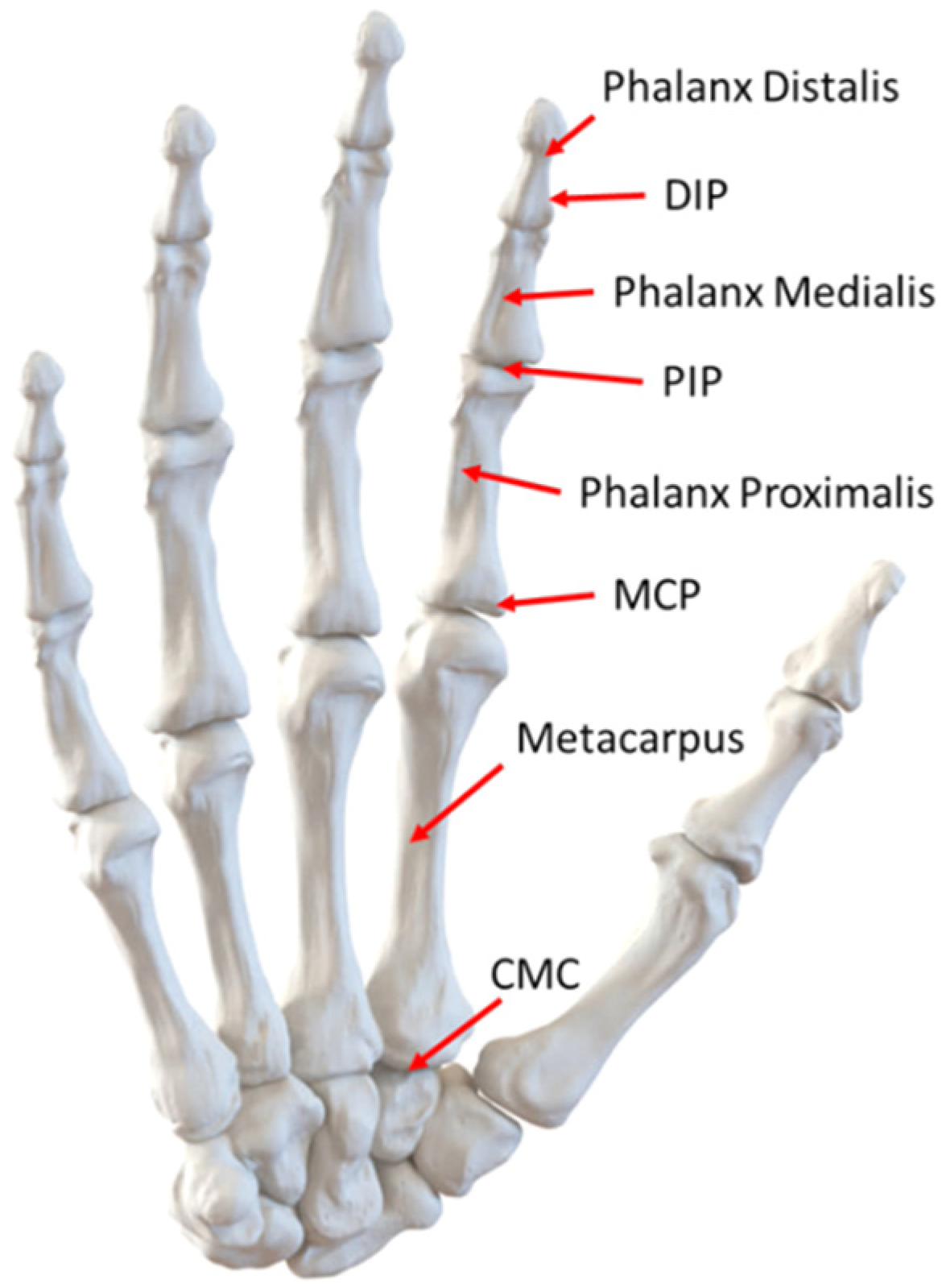
A human hand is composed of fingers, metacarpus, and carpus. The fingers consist of three phalanxes, except for the thumb, which consists of two phalanxes. The metacarpus is connected to the proximal phalanx. On the fingers, the second link is the medial phalanx. The third link is the distal phalanx. A detailed description of the joints and functionalities of a human hand can be found, for example, in [
35,
36]. The joints between the intermediate and distal phalanxes are called distal interphalangeal joints (DIP), and the joints between the proximal and intermediate phalanxes are called proximal interphalangeal joints (PIP). The metacarpophalangeal joints (MCP) connect the proximal and metacarpal phalanxes, and the carpometacarpal joints (CMC) connect metacarpal phalanxes and the carpal bones, as shown in the scheme of
Figure 1, [
36]. In general, flexion reduces the angle between bones or parts of the body, whereas extension increases the angle between the bones of a limb. Abduction is an outward movement of a limb, and adduction is an inward movement of a limb [
9]. The MCP joints have two DOFs and they allow flexion and extension as well as abduction and adduction of a finger. The interphalangeal joints PIP and DIP have one DOF each. However, the axis of rotation of these joints is not constant during flexion and extension [
10], and the ligaments restrict the movements of the joints. Moreover, DIP and PIP joints cannot be moved independently of each other [
35].
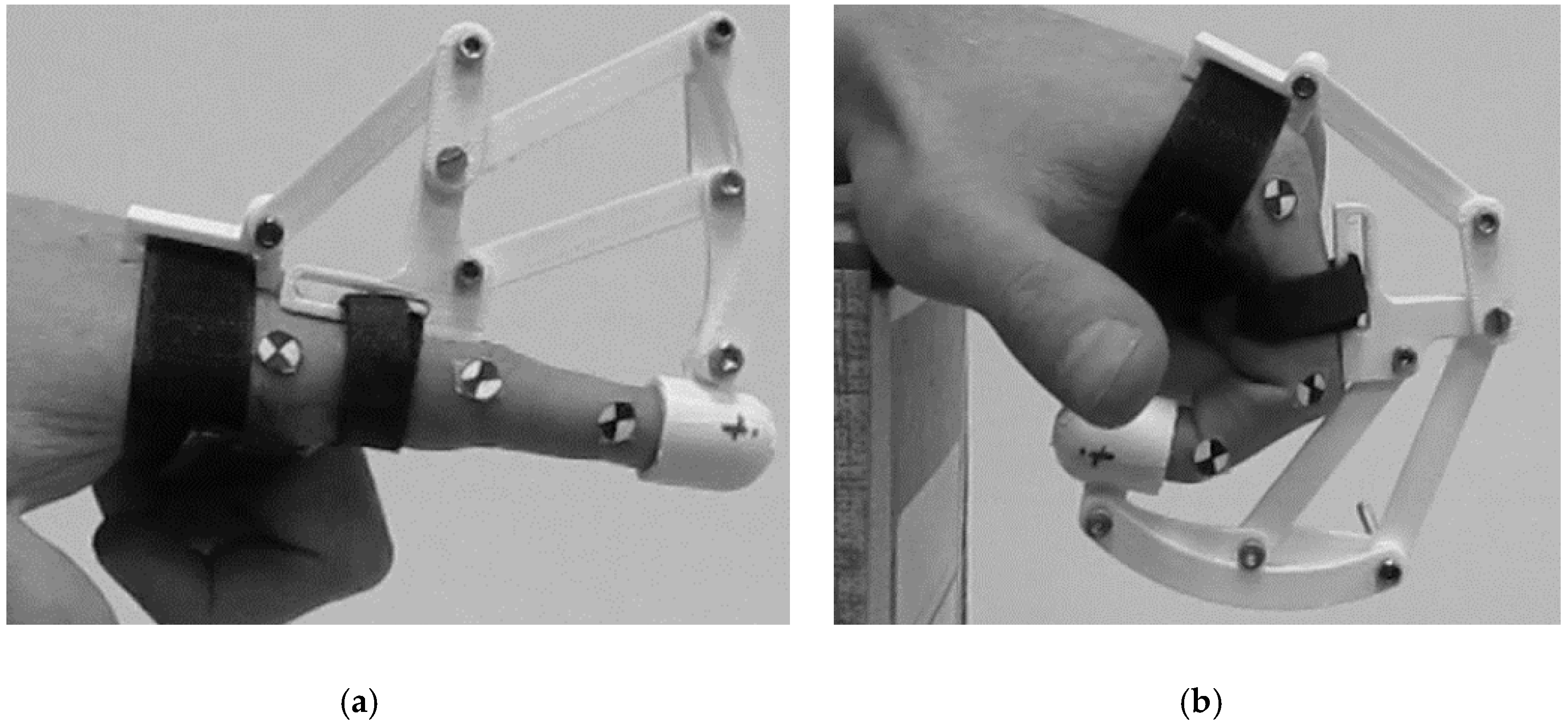
A finger exoskeleton can be conveniently designed for motion exercising of the muscles after an injury or a stroke. For this application, the motion of a finger will be assisted by the exoskeleton with a motion trajectory similar to a healthy finger of the same size as proposed in
Figure 2. The motion trajectory does not require high accuracy. For example, in [
11], a misalignment of a phalanx up to ±8° is deemed acceptable. However, unnatural movements of the finger must be avoided by the mechanism to prevent potential injuries. As an additional design requirement for a finger exoskeleton, its installation space needs to be small enough to be attached onto the finger and not interfere with its motion. For the same reason, the total weight of the system should not exceed 500 g as reported, for example, in [
7,
13,
17]. This value should be considered an upper bound, since a heavy exoskeleton can limit the effectiveness of motion exercising. Indeed, a high weight makes a patient easily tired and not willing to continue the treatment. Thus, it is advisable to limit the number of motors as they are the main source of weight. Motors need to provide a minimum torque of around 200 Nmm as reported previously [
3,
7].
One of the main peculiarities of the proposed novel linkage mechanism design solution is that it can move all three phalanxes of a human finger with two active DOFs. This is mainly achieved by coupling the motion of the last two phalanxes. Accordingly, only two DOFs are needed to replicate whole finger motions. The proposed mechanism is optimized to perform a specific desired motion but it is actually able to perform a wide range of other motion combinations, given its two active degrees of freedom. The proposed design is limited to flexion and extension movements of a finger. However, flexion and extension are identified in literature as the most important for activities of daily life and the first recovery priority in case of finger injury, as also mentioned in [
35,
36]. Therefore, a motion assistance mechanism at first instance does not need to focus on abduction and adduction movements, and these movements can be safely neglected to achieve a device with a light and simple design.
3. Kinematic Design
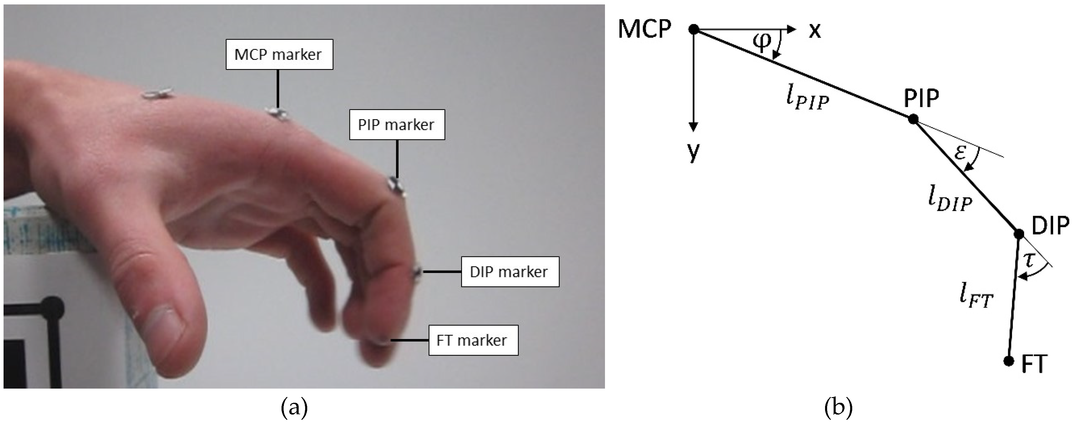
The index finger of a healthy subject has been used as a reference to develop and validate the proposed novel exoskeleton. First, grasping motions have been analyzed by using the Computer Vision Toolbox of MATLAB (Mathworks, Natick, MA, USA). Markers have been attached to the joints of the index finger and its fingertip (FT). Distances between the markers have been also measured with a digital caliper for calibration purposes. The camera has been aligned perpendicular to the side of the finger under study, and a fixing frame has been used both for the hand and camera in order to achieve a planar motion of the finger and a fully orthogonal video recording. The acquired videos have been post-processed to collect positions of the joints versus time.
Figure 3 shows the experimental setup for the finger motion tracking as well as the definition of the angles and reference frame with the x-axis horizontal oriented from left to right, and the y-axis vertical oriented from top to bottom. The z-axis is defined according to the right-hand rule. The origin of the reference frame is attached to the center of the MCP joint. The angle of the MCP joint is called φ, the angle of the PIP joint is called ε, and the angle of the DIP joint is called τ. The angles have a clockwise positive direction.
The lengths of the phalanxes of a test subject were identified from set-up measurements as 25 mm for the distal phalanx, 28 mm for the medial phalanx, and 43 mm for the proximal phalanx. Twenty-two frames have been evaluated from the motion tests for a suitable finger motion characterization.
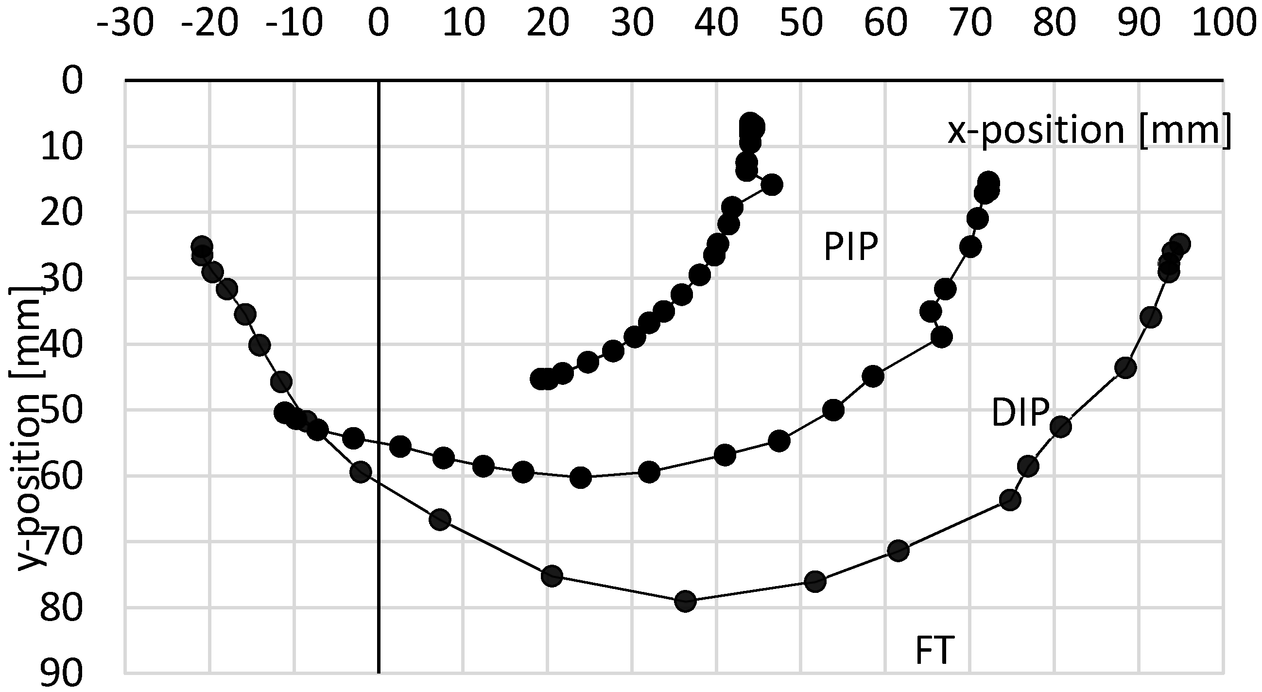
Figure 2 shows a detail of a video-captured motion for a healthy human finger movement referring to a typical human finger motion. In particular, the plot in
Figure 4 shows trajectories of PIP, DIP, and FT markers during the motion of an index finger that moves from fully open to fully close. These trajectories will be used as the reference motion trajectories for the linkage mechanism of the proposed novel exoskeleton. However, the desired exercising motion usually does not require the full joint feasible rotation range of the motion range of a healthy human finger but only a subset of such a motion.
Moreover, it is advisable to avoid full finger closing as this would result in an undesired interference with the palm. A specific linkage mechanism has been identified as convenient for mimicking the desired reference finger motion. This proposed mechanism consists of eight links that are arranged as two interconnected four-bar mechanisms. This specific linkage arrangement has been proposed as an Italian patent [
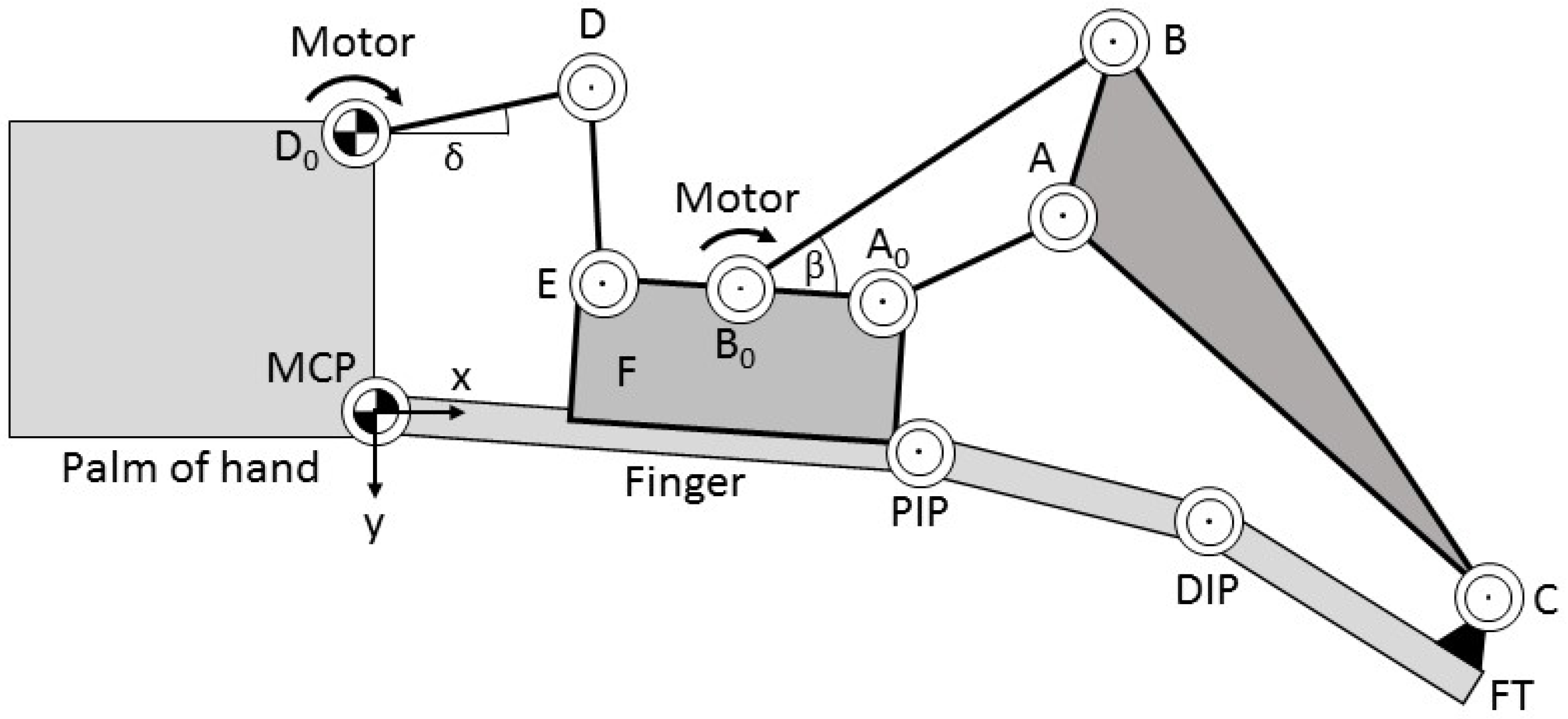
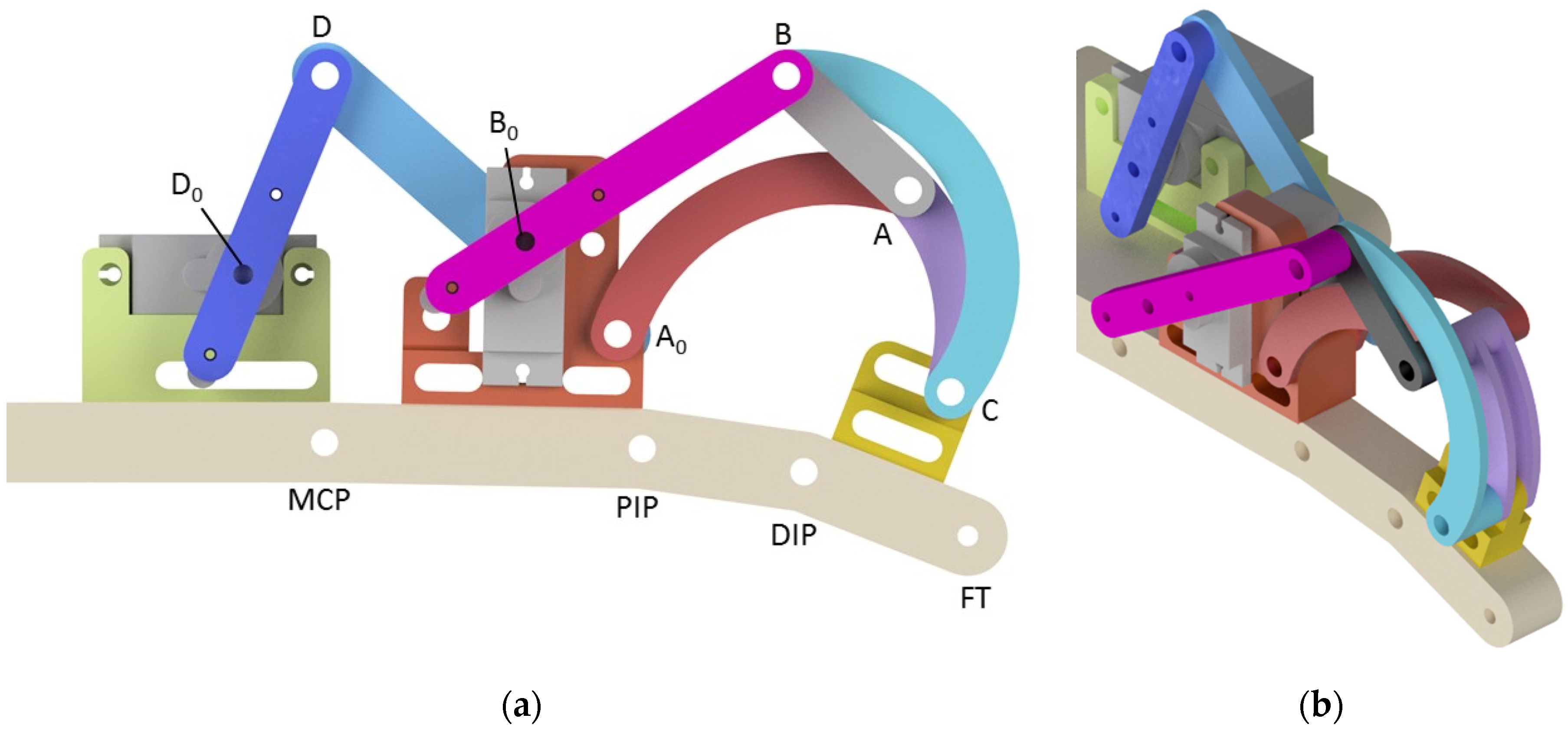
34]. The proposed mechanism requires two motors that each drive one of the two four-bar mechanisms. A detailed kinematic scheme is shown in
Figure 5. The motors are located at joints D0 and B0. The angle of driving link D0-D is called δ. The angle of the driving link B0-B is called β. Both angles are positive in a clockwise direction. The first four-bar linkage (D0-D-E-MCP) has four links and four revolute joints with one active DOF. The second four-bar linkage (B0-B-A-A0-C) has one active DOF, four links, and four revolute joints.
The second four-bar linkage drives the point C that is attached to the fingertip (FT). The exoskeleton is also attached to the palm at the fixed frame link D0-MCP and to the first phalanx with the link E-B0-A D, as shown in
Figure 5.
For the first linkage, the link lengths need to be chosen by considering the dimensional constraints of the motor and the palm of a hand. Accordingly, the link length D0-MCP is close to the vertical dimension of the selected motor. The link length E-MCP is mostly determined by the geometrical constraints for the attachment of E-B0-A to the first phalanx. The link lengths D0-D and D-E need to be calculated to fulfil the desired motion trajectory of the PIP joint, according to the motion reference in
Figure 4. Considering the finger in fully close configuration, one can identify that in this configuration, the longest distance is expected to be D0-E. This distance can be calculated as 63.3 mm from the reference motion data. For achieving this value, the link length
has to be equal to 27.8 mm, the link length
has to be equal to 32.0 mm, and the link length D-E has to be equal to 58.1 mm. Joints E and A0 on body F have coaxial axes.
To size the link lengths of the second linkage mechanism, a graphic/geometric synthesis dimensional synthesis has been carried out to obtain the desired motion of point C. The procedure is reported as a general formulation, for example, in [
35]. The dimensional synthesis starts by calculating the desired relative motion of point C relative to A0 based on the experimental data in
Figure 3 and
Figure 4 and on the relative position of the joints in the proposed linkage mechanism shown in the scheme of
Figure 6. In this scheme, γ is the angle between the horizontal axis and line through A0, α is the angle between the horizontal axis and line through C, and η is the difference between the angles. The relative coordinate system is located in A0 and has its p-axis along the line
, as shown in
Figure 6.
The u-axis is perpendicular to the p-axis with direction from top to bottom. Δc is the distance between A0 and C along the p-axis, and Δd is the distance between A0 and C along the u-axis.
The coordinates of point PIP are known from the measured trajectory of the finger movement in
Figure 4. The displacement of the PIP point and A0 is shown in
Figure 7 where φ is the angle between the horizontal axis and line through PIP, while
is the angle of MCP from A0 to PIP. The distance between MCP and A0 is
, and the distance between MCP and PIP is
. Parameters a and b represent the displacement between A0 and PIP. The coordinates of point A0 can be calculated by using the parameters a and b and the angle γ. Since the angle
and the length
are known from the calculations of the reference trajectory in
Figure 4,
can be calculated as
Therefore, referring to
Figure 7, the angle
is given by
The coordinates of A0 can be calculated as
By squaring and summing Equations (3) and (4), it is possible to obtain
A similar procedure is used to calculate the global coordinates of C.
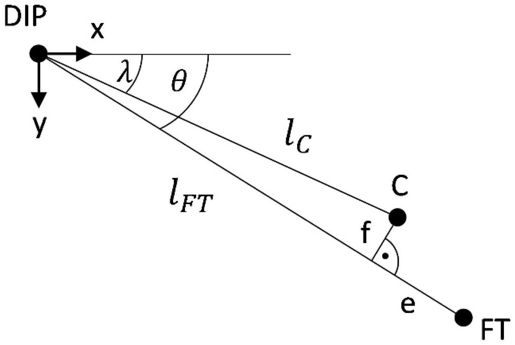
Figure 6 shows a sketch for the displacement between FT and C, where λ is the angle between the horizontal axis and the line from DIP to C; θ is the angle between the horizontal axis and the line from DIP to FT. The distance between DIP and FT is
, and the distance between DIP and C is
. Parameter e is the displacement between FT and C on the line from FT to DIP, and f is the displacement between C and FT perpendicular to that line.
The global x and y coordinates of DIP and FT are known from the captured trajectory in
Figure 2. As given in
Figure 8, the link orientation, given by angle
, can be calculated as
Therefore, the angle
is calculated as
The global coordinates of C can be calculated as
Consequently,
is calculated as
Finally, distances Δc and Δd can be computed as
The resulting parameters from the above-mentioned calculations for the offset of A0 and C are summarized in
Table 1. The parameters are obtained from measurements on the finger of the subject and also referring to an early prototype. The diameter of a reference finger has been measured to calculate the distance from the finger joint to the top of the finger, giving parameters b and f. Parameters a and e were identified from a preliminary prototype, which showed that A0 could be placed directly above the PIP joint, whereas C requires some distance from FT to avoid slipping off the finger during motion. With the calculated positions of joint C, the dimensional synthesis of the second linkage mechanism can be conducted.
No singular configuration is reachable within the used workspace of this mechanism. This has been verified at the design stage by setting up limits at the feasible transmission angles, and it has also been verified experimentally.
4. Mechanism Synthesis of the Second Linkage
The dimensional synthesis of the second linkage can be outlined as the procedure of determining the remaining lengths of a 4-bar mechanism that guides a point on the coupler curve. One possibility for such a synthesis is the graphical method based on the Burmester theory as described in [
37]. This synthesis approach has been selected since it can quickly address the desired features in terms of replicating a desired motion trajectory as given by the reference motion trajectory in
Figure 4. The expected accuracy for joints (±4 degrees) does not justify the use of more complex and time-consuming synthesis methods such as numerical optimization.
The proposed procedure allows an approximation of the desired movement from the measured trajectory in
Figure 4 by defining three points on the coupler curve that are reached precisely by the mechanism. The synthesis can be conducted when two lengths of a mechanism and two positions of joints are known.
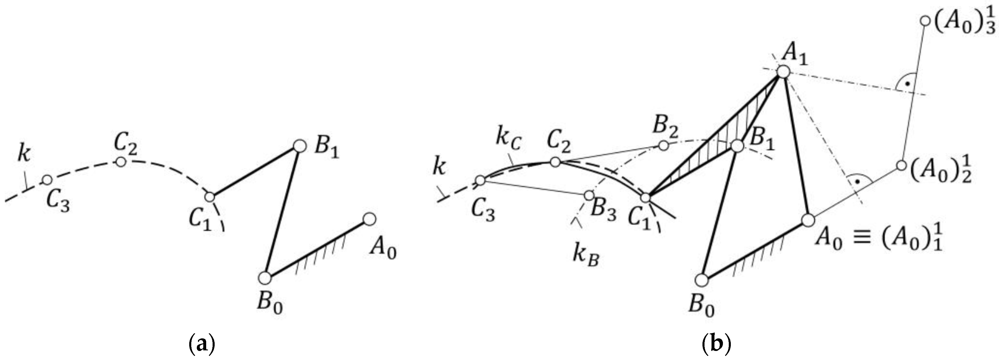
Figure 9a shows the initial problem with all given parameters. The position of joints A0 and B0, lengths
,
,
, and three positions of joint C are given in the initial problem. From the input, the position of the missing joint can be determined. When the positions of all joints are established, the lengths can be determined. Curve k in
Figure 9a shows the original movement of joint C, and curve kc in
Figure 9b is the movement after the synthesis. With the synthesis in
Figure 9b, joint A can be determined, giving the missing lengths
,
, and
.
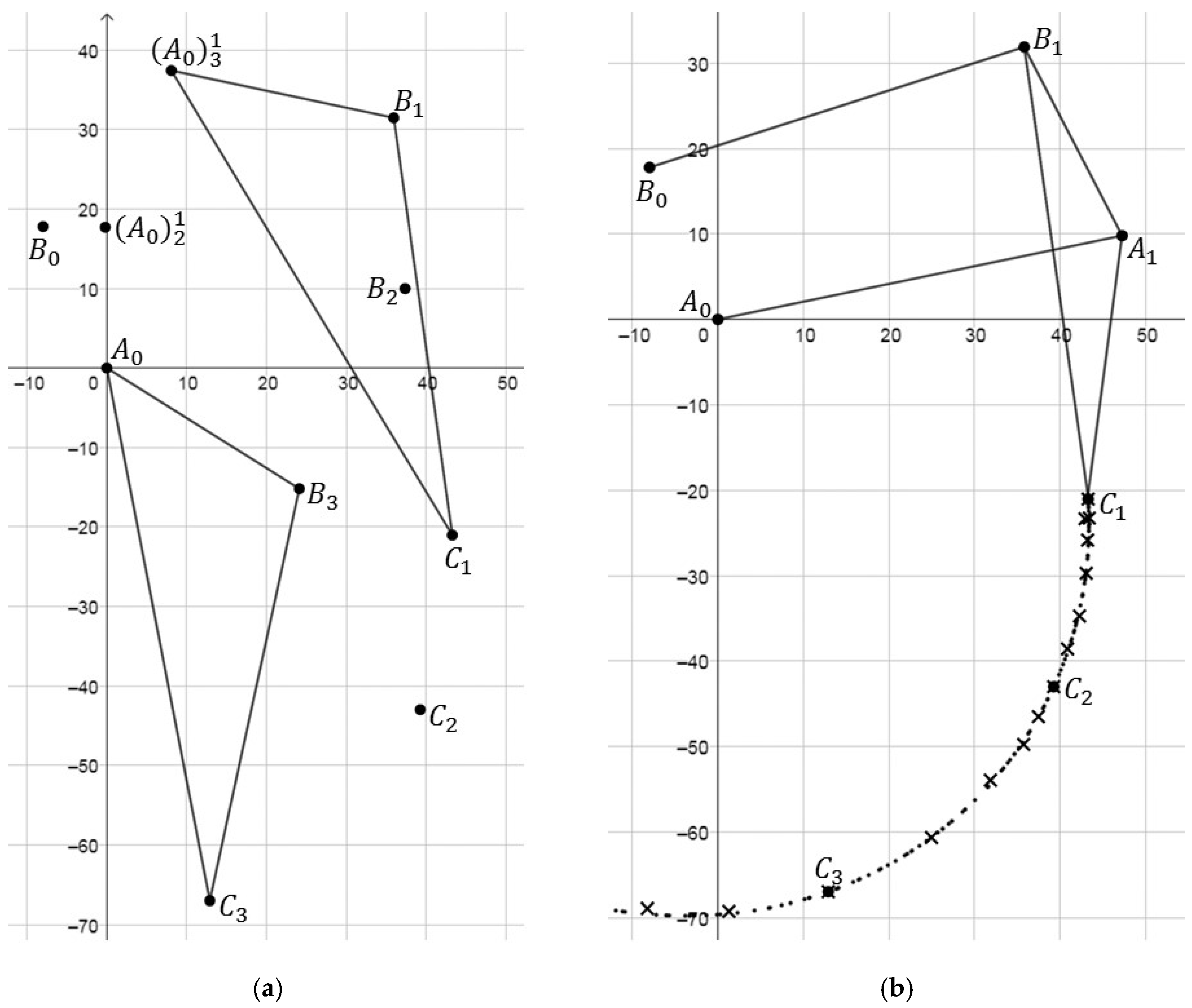
A pose of a mechanism consists of the positions and the orientations of all links. For example, for pose 1 of the mechanism in
Figure 4, joint A is in position A1, joint B is in position B1, and joint C is in Position C1. The graphical procedure for the dimensional synthesis is given in the flow-chart of
Figure 10 according to the following steps:
The given parameters in
Figure 9a are the positions of C1, C2, C3, and B0 as well as the lengths of
and
;
With the information from step 1, joint is known in pose 1, 2, and 3, as joint B moves on the curve kB. Therefore, the poses of , , and are known. At this point, joint A is missing to complete the mechanism sizing:
Next, one link in one pose is chosen as a reference (in this example, link BC in pose 1);
Now, joint is virtually moved around to create A0 that corresponds to position 2 in pose 1 (by moving A0 with respect to the coordinate system of pose 2 into pose 1). The transformation can be done by creating a triangle between C2, A0, and B2 and moving the triangle into the pose of C1 and B1. The resulting position is from pose 2 in pose 1, written as ;
The same as step 4 is done with from pose 3 in pose 1, resulting in ;
Finally,
is found by the intersection of the perpendicular bisectors between three positions of
. The resulting mechanism guides joint C along curve kC. Curve kC matches curve k in the points C1, C2, and C3 [
33];
With all known positions of the joints, the link lengths can be determined.
Other link lengths/positions can be chosen to improve the matching of curves k and kc.
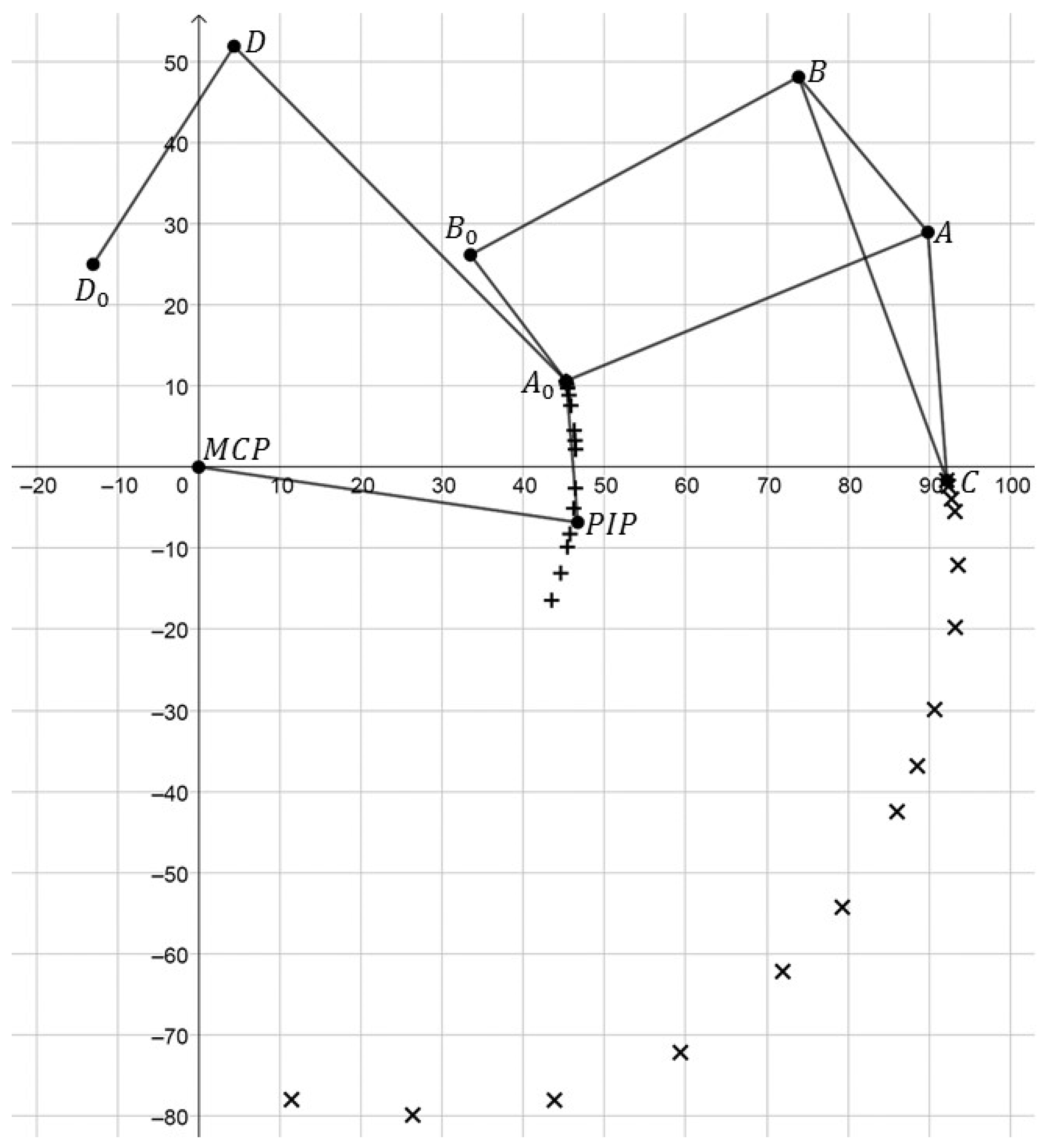
The dimensional synthesis is applied to the second linkage mechanism by using the relative movement of C with respect to A0. The aim is to design a mechanism that matches the desired motion trajectory of point C.
The positions of point C with respect to the u-p coordinate system are calculated by Equations (11) and (12). For the dimensional synthesis, the positions of A0, B0 and the lengths
and
are required as well as three reference positions of C within its desired motion trajectory, according to step 1 in
Figure 10. A0 and B0 are set as frame joints. A0 has the coordinates (0; 0) with respect to the u-p-coordinate system. B0 is designed with the coordinates (−8; −17.8). The input parameters have been iterated to find a mechanism that fulfills the desired path of C well. After few iterations, sufficient input parameters were found. Positions 1 to 15 of the calculation of point C have been considered for the synthesis, as it gets more difficult to approximate a longer motion path. Furthermore, the identified range of motion is sufficient for rehabilitation purposes.
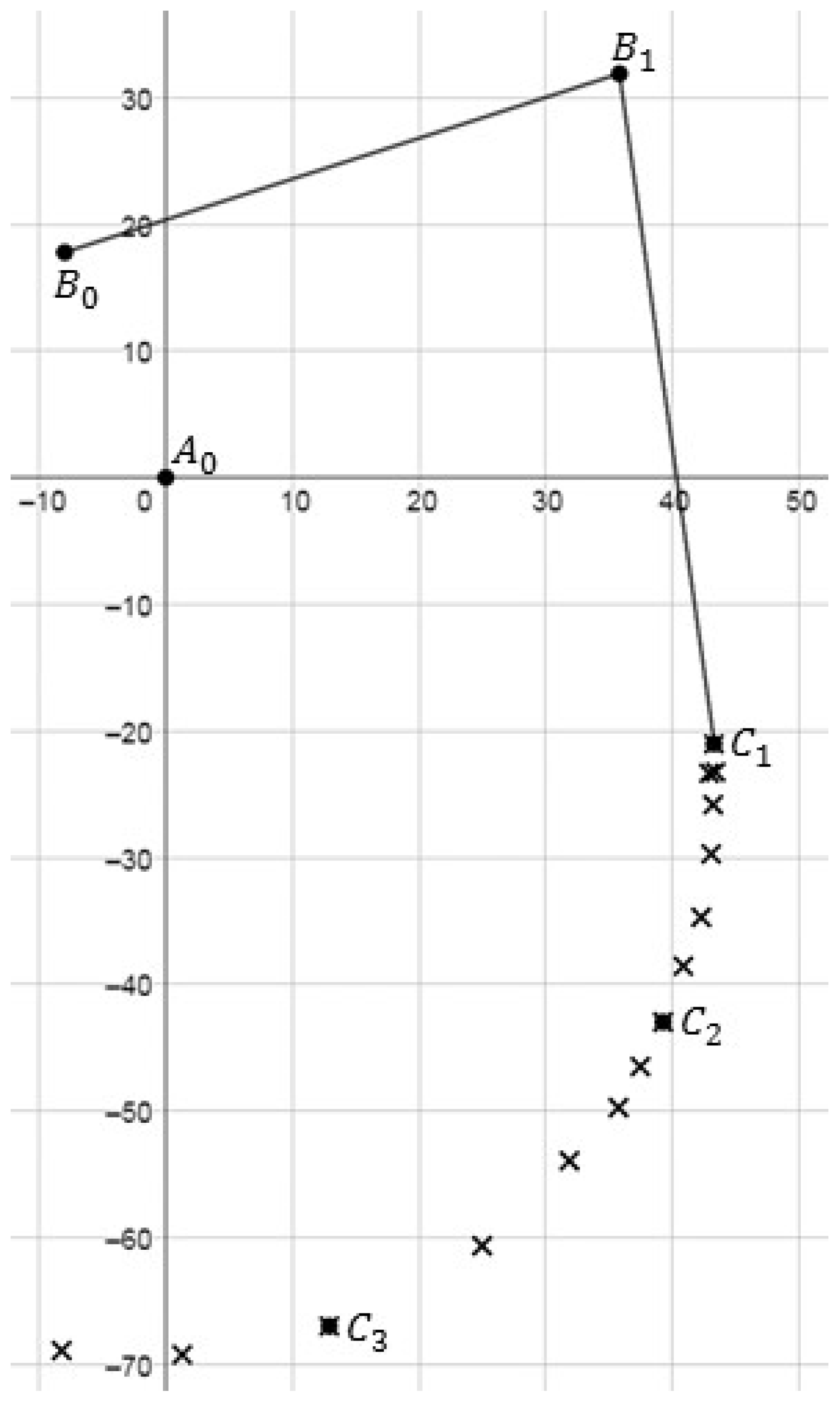
The initially chosen link lengths and point coordinates are shown in
Figure 11, similar to
Figure 4. With this information, positions B2 and B3 can be determined as intersecting points with the known segments of
and
, as mentioned in step 2. As a result of iterations of the synthesis,
has been measured to have a length of 46 mm, and
. has been measured to have a length of 53 mm. As input from the positions of C, the first position is chosen as C1, position C2 is in the middle, and position C3 refers to the last used configuration during the finger closing motion. According to step 3, pose 1 is the reference for the synthesis. A0 with respect to position
is transferred into position
, resulting in
.
is A0 in pose 3 transferred to pose 1. This means that the triangles C3-B3-A0 and C1-B1-
are identical. In the same manner, the point
can be identified. This corresponds to step 4. The triangles to find the position
are given in
Figure 12a. The synthesized mechanism and the calculated positions of C are shown in
Figure 12b. The previously calculated coordinates for C are marked as crosses, and the computed trajectory of the mechanism is marked as dots. The figure also shows that the trajectory matches well with the desired motion for point C.
The position of A1 is the center point of a circle through the positions A0,
and
, as mentioned in step 5. The resulting position is A1, as pose 1 has been used as a reference. The link lengths can be determined with the obtained position of A1. Since the given data in step 1 have already been identified by a prior iteration, step 7 can be skipped. The complete kinematic design is obtained by combining both linkages. The resulting kinematic design of the whole exoskeleton mechanism is shown in
Figure 13. The numerical values are summarized in
Table 2, defined according to the scheme in
Figure 5. The calculated positions of A0 and C are indicated with plus (+) and cross (x) marks, respectively.
This paper reports the proposed graphical procedure for a specific case with nominal biometric measurements. However, the proposed graphical procedure is general in its approach. Accordingly, the same procedure can be performed again for different finger sizes when the phalanx lengths are expected to exceed the adaptability allowed by the proposed design. A chart can be generated with link dimensions for different patient biometrics to adapt the proposed finger exoskeleton to the wearer. Moreover, the proposed synthesis procedure can be also automated by implementing it in a numerical solving algorithm.
5. Mechanical Design and Prototype
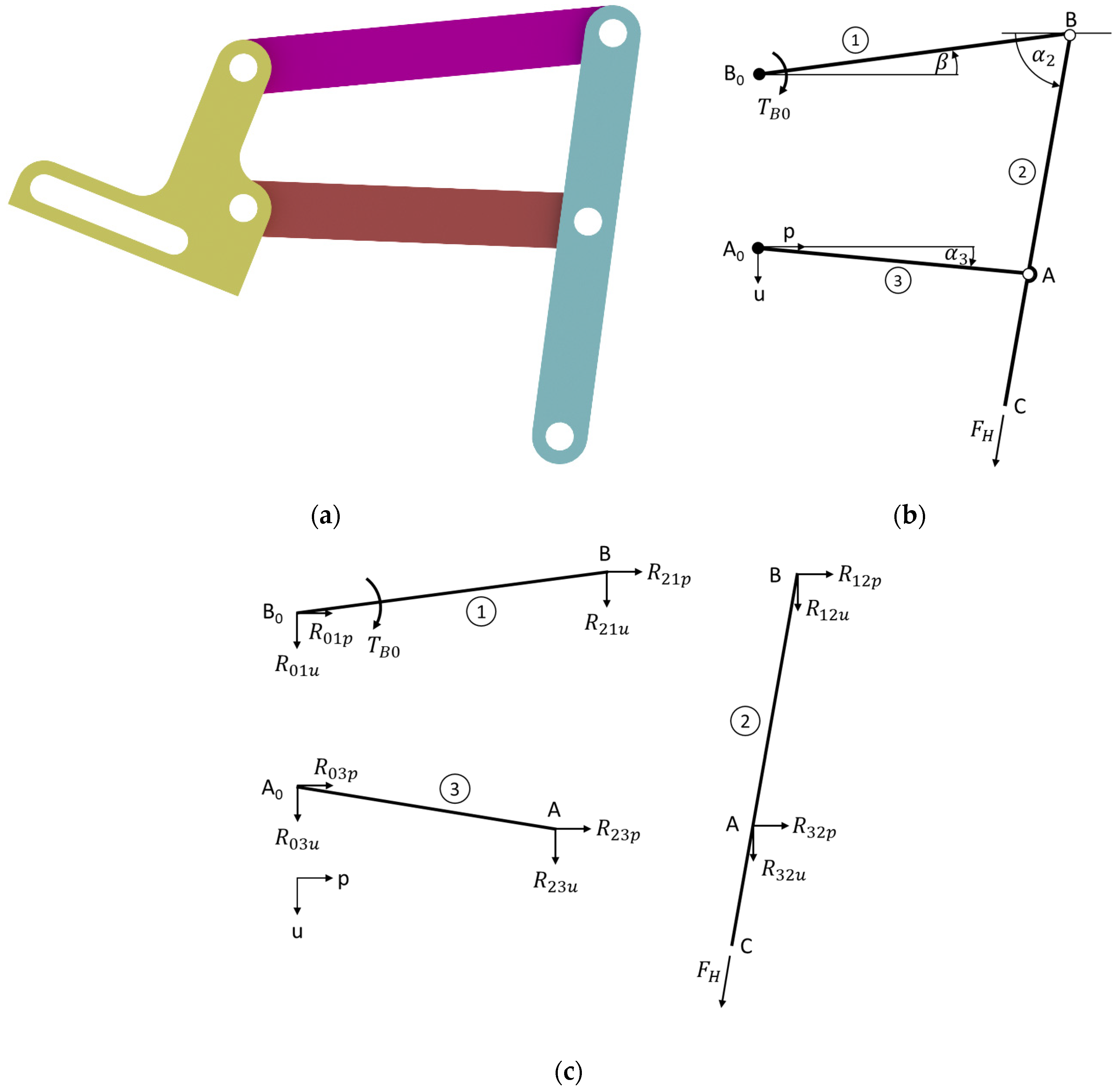
Based on the obtained kinematic design, a prototype of the proposed finger exoskeleton has been developed. Since the finger exoskeleton is manufactured by 3D printing, it has been necessary to define the secondary geometric parameters of each linkage, such as link thickness. For this purpose, given the slow speeds, accelerations, and inertias of the application, a specific static analysis has been carried out according to the schemes that are shown in
Figure 14. The computation has been carried out by considering as load the maximum motor torque of 216 Nmm, and a maximum force at the connections between finger and exoskeleton equal to about 6 N on the fingertip. This value is calculated by using the principle of virtual powers from the given input torque and also matches previous experiences of similar prototypes.
FEM analyses have been carried out iteratively to find a proper linkage cross section and thickness. In particular, final FEM simulations have been carried out by considering the 3D CAD model that is shown in
Figure 15. The main link thickness has been set as equal to 2 mm, also based on previous experiences. Similarly, the holes for the joints have been set at a diameter of 4 mm. Therefore, the links need to have a total width of 8 mm and a thickness of 2 mm. Link
is crooked as per
Figure 15 in order to avoid collisions with the finger, and link
is crooked to allow for fixation of the joint A. Even though
behaves kinematically as a single body, it is realized with three different links that can be easily changed to fit the different finger sizes of different users. The link
is manufactured with two beams to increase its stiffness. A CAD design has been elaborated with the above-mentioned design considerations. A functional solution of the mechanism with all its joints is shown in
Figure 14. Screws and nuts of M3 size connect the links.
The main merit of the proposed design can be identified in the adaptability to multiple users. This is achieved by slotted holes (
Figure 15) in the exoskeleton that allow easy adjustability to users. The slotted holes are used to adapt the finger exoskeleton to the user’s biometrics (phalanx lengths) by moving each link to the optimal configuration evaluated through the proposed dimensional synthesis. Cable straps and loop fasteners are used to fix the exoskeleton on the finger, giving some additional adaptability. Accordingly, the proposed exoskeleton is expected to fit users having specific phalanx sizes exceeding ± 10% of the nominal sizes. A design limitation can be identified in the need to replace the links of the device when users are expected to exceed ± 10% of the nominal finger size. This limitation can be partially overcome by preparing sets of replacement links whose sizes are designed to fit with different nominal finger sizes (e.g., for children, male/female adults).
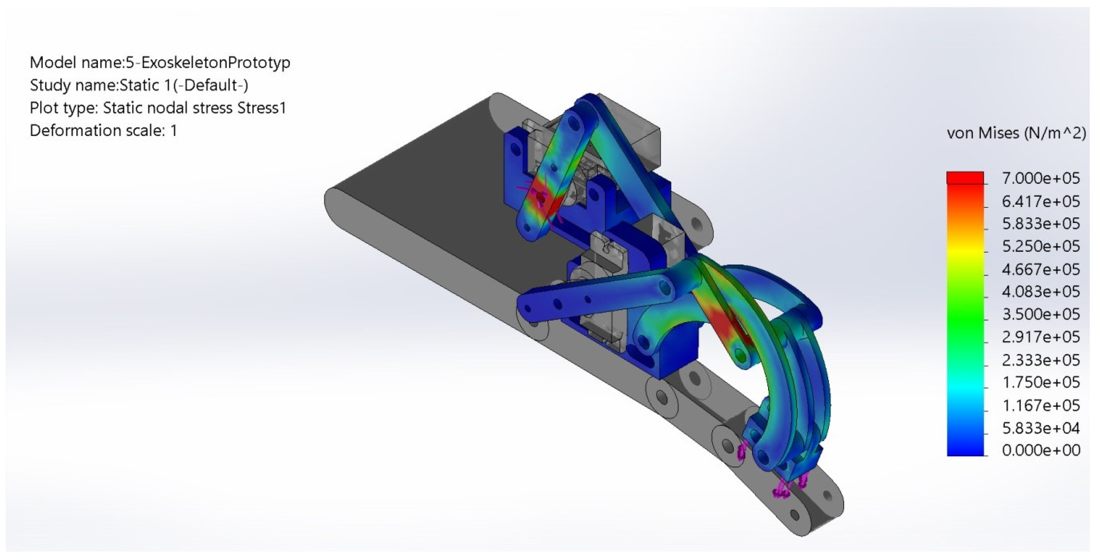
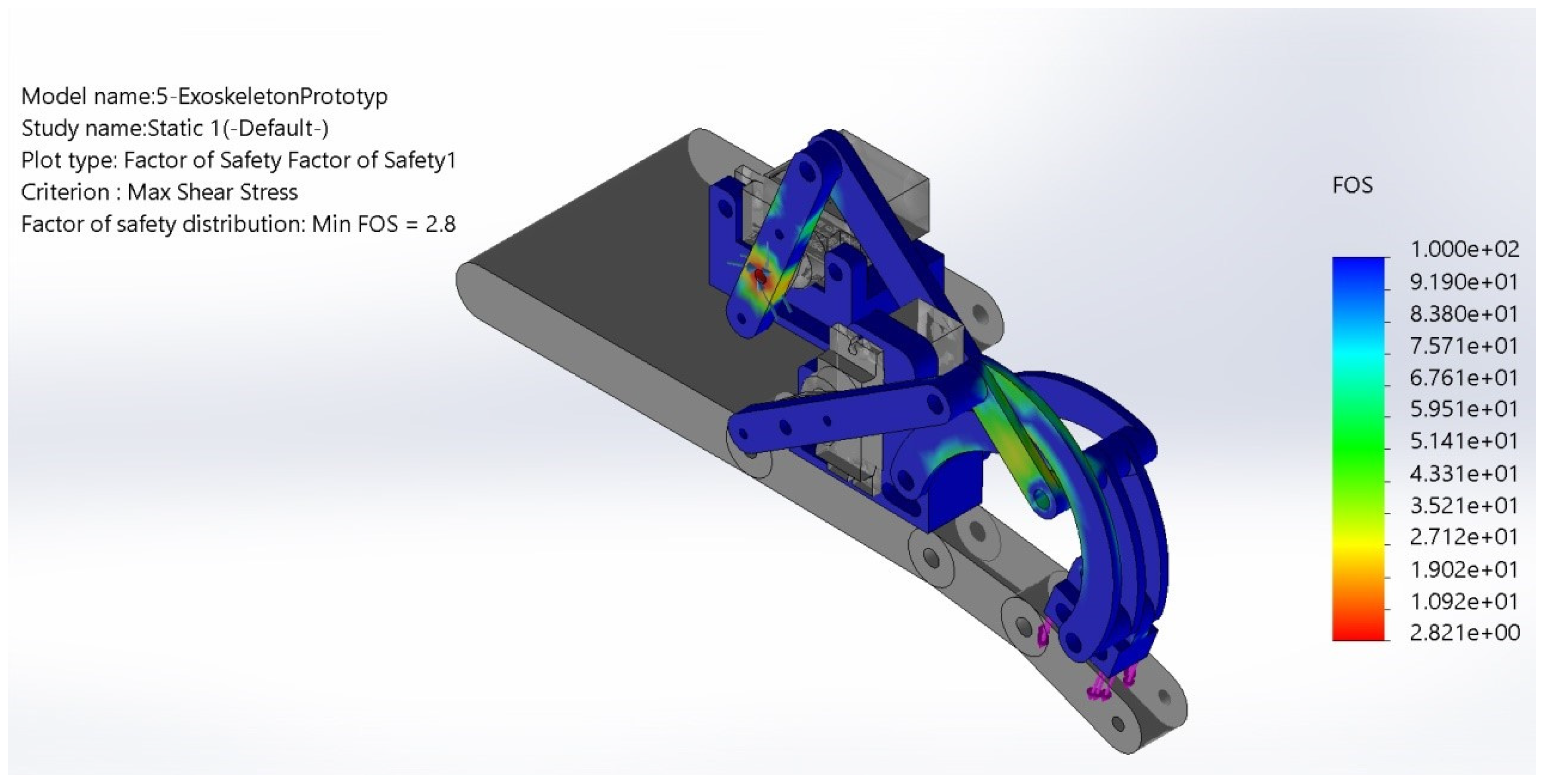
Final FEM tests have been performed in SolidWorks 2019 to verify the correctness of the selected cross-sections and minimum required thickness to avoid any failure or plastic deformation, as reported in
Figure 16 and
Figure 17. A minimum safety factor equal to 1 has been considered in static nodal stress analysis for keeping the overall weight as low as possible. A minimum factor of safety equal 2.8 has been found on shear stress. The chosen material is a commercial poly-lactic acid (PLA) filament that is suitable for additive manufacturing with commercial 3D printers. Its main properties are tensile strength equal to 3∙10
7 N/m
2, elastic modulus equal to 2∙10
9 N/m
2; Poisson’s ration equal to 0.394, mass density equal to 1020 Kg/m
3, and shear modulus equal to 3.189∙10
8 N/m
2.
The size of motors has been chosen to match the results of simulations for the designed mechanism as well as by comparison with similar devices in the literature. Both servo motors have been selected with a nominal torque of 216 Nmm while the desired torque was about 200 Nmm for the first joint and about 150 Nmm for the second joint. Servo motors with a torque of 216 Nmm are integrated into body F and lay on the back of the palm of the human hand. An Arduino microcontroller has been chosen to drive the motors.
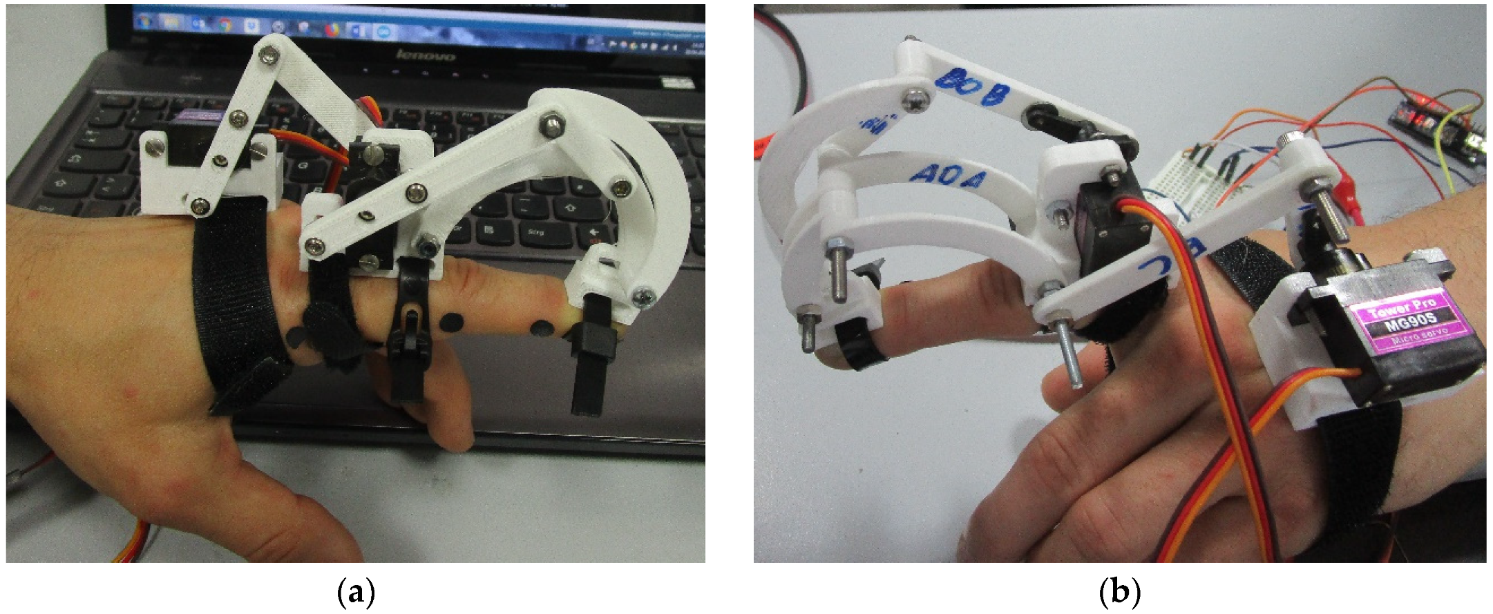
The total cost of the system is around 50€, including the servomotors and the microcontroller. The motors are connected to an external power supply, which can be a LiPo battery for easy portability. The exoskeleton has a total weight of 64 g for the parts that are mounted on the finger. This includes the linkage, cable straps, hook and loop fasteners, and servo motors. The whole system has a weight of 175 g, including an Arduino board and all cablings. A full prototype has been built as shown in
Figure 18.
6. Test Results
The built finger exoskeleton prototype has been tested experimentally to prove its feasibility as a finger motion exercising device in terms of it kinematic and operation behaviors. Given the expected slow speed operation, dynamic simulations and tests are not required at this proof-of-concept stage. The finger exoskeleton can be easily worn with Velcro fasteners. The connection between the finger and exoskeleton can be as tight as the subject wishes. Even after long use, it is still comfortable to wear. Also, the calibration procedure is very straightforward. It consists of the following steps: Attaching the exoskeleton to the finger, manually placing the finger in its desired straight configuration; registering this position as the initial configuration; manually placing the finger in its desired fully closed configuration; registering this position as the fully closed configuration. After the above steps, the device is ready to operate within the desired operation range.
The exoskeleton movement has been compared with the reference motion of a healthy human finger, and the angular error has been calculated as also partially reported in [
33]. The driving angle of joint D0 is called δ, and the driving angle of joint B0 is called β. The angles of the joints of the finger from the grasping test have been used as an input for a multibody motion simulation of the CAD model on SolidWorks 2019. The simulation acquires the angles of the motor for each position during the finger motion. A comparison of the simulation and the motion of the prototype was used to determine if the exoskeleton prototype moves as planned.
The desired path planning and angular joint coordinates are managed by using an Arduino control board, which is connected to the two servomotors that drive the exoskeleton. The angles of the driving links have been calculated and interpolated for each position that has been experimentally measured during a grasping test, as reported in
Figure 4. Then, the obtained motor angles are sent to an Arduino controller, which drives the exoskeleton. The desired motion has been obtained by an offline video post-processing that is carried out with MATLAB, allowing us to measure the angular joint positions in each acquired video frame. This information is converted into a desired set of joint angles versus time. The controller is programmed to move both motors in each desired position with an interpolated step motion. Accordingly, the proposed motion planning consists of passing through a prescribed number of path points with a smooth interpolated motion to reach precision positions. A pause of half a second is set before proceeding with the next step desired precision position to keep the motion safe for the user. The user has the time to easily stop if he/she feels discomfort in any reached configuration. The maximum angular reaches of motors are limited via software limits that are well within the range of the servo motors being equal to 180°. After completing the motion planning, videos of human finger exoskeleton-assisted motions were collected and analyzed. Tests were performed on the same subject as for the initial grasping test in
Figure 1 and
Figure 3.
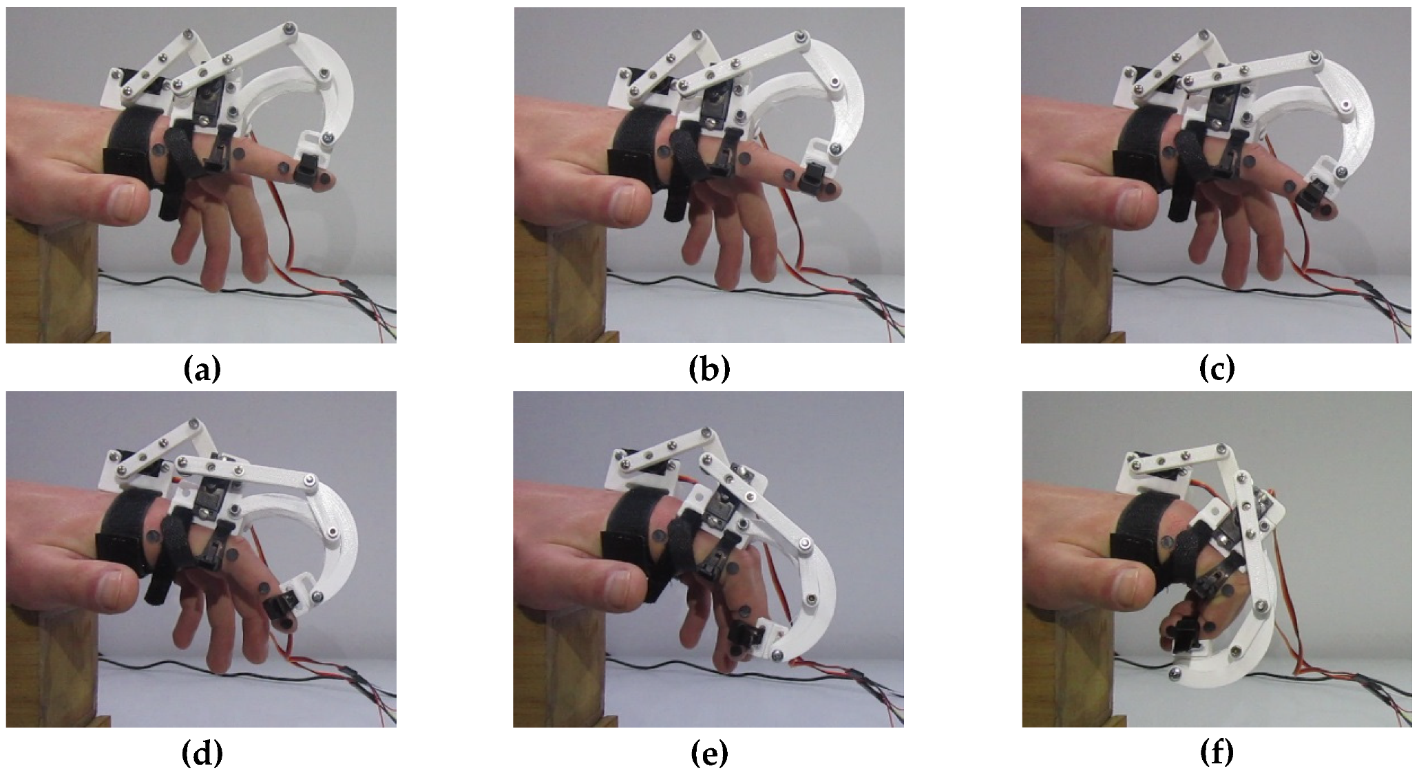
Video captures were acquired by tracking both finger joints and exoskeleton joints during a grasping motion. Then, the driving angles and the angles of the finger were determined. The resulting movement of the prototype and the finger is shown in
Figure 19. The movement takes approximately 16 s. The proposed tests are performed with a human sitting and his/her forearm fixed on a reference table. The first snapshot
Figure 19a refers to the beginning of the movement. Snapshot
Figure 19b is taken after 3.2 s, snapshot
Figure 19c after 6.5 s, snapshot
Figure 19e after 9.7 s, and snapshot
Figure 19e after 13.0 s. Snapshot
Figure 19f shows the final position of the motion. In this test, the MCP joint moves within a range of 3.1° to 37.6° for a finger flexion. Similarly, the PIP joint goes from 13.0° to 78.7°, and the range of the DIP joint is from 0° to 58.9° for a finger flexion.
The time history of the measured finger joint angles is given in
Figure 20. for a finger flexion assisted by the exoskeleton. Namely,
Figure 20a–c show the acquired values of angles φ, ε, and τ versus time, respectively. Moreover, (x) markers are reported in
Figure 20 to show the simulated angular motions angles of φ, ε, and τ versus time. In the plots of
Figure 20, an initial offset can be observed between the measured and simulated values. The maximum velocity and swing frequency of the finger exoskeleton mechanism are defined by means of a reference finger-assisted motion. This motion needs to be very slow to allow safe finger motion assistance, so a fast speed is not desirable. In particular, for the prototype reported in the paper, the average velocity is 5 deg/s, with a swing frequency of 0.07 swings/s. From a practical point of view, this initial offset is mostly due to manufacturing/assembly errors as well as joint clearances. These effects can be seen also as positive in terms of adaptability to a more natural finger trajectory.
The absolute error of the angular positions of the finger joints can be calculated by comparing the two curves in
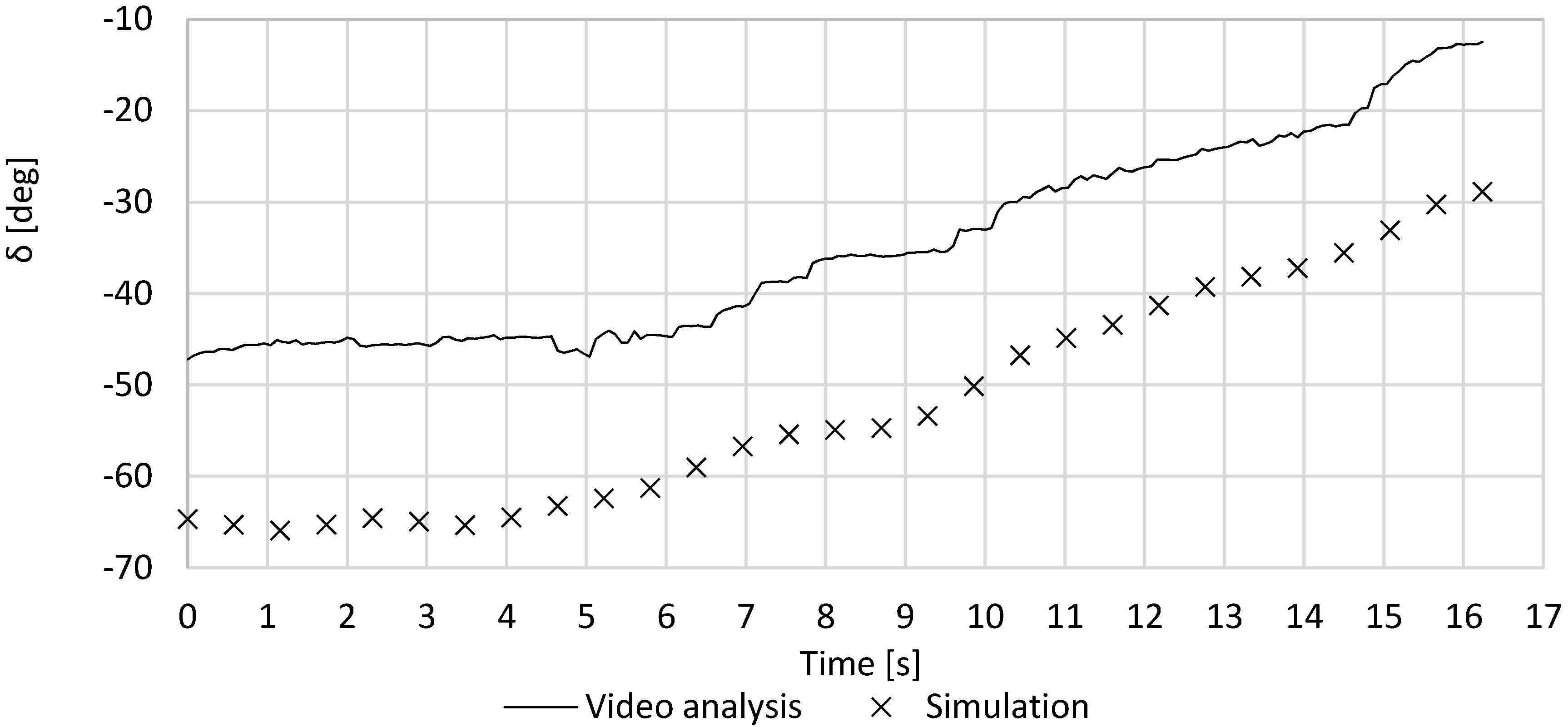
Figure 20. To compensate for an initial misalignment, a systematic error can be calculated. Moreover, an angular deviation error can be calculated as the difference between the experimentally measured and simulated values at a given time. For example, the time history of the angle δ is given in
Figure 21 including both simulated and experimentally measured values. The experimentally measured angle δ versus time goes from −47.2° to −12.5° in this test. The comparison between the experimentally measured and simulated angle δ versus time shows an initial systematic error of 17.5°. If this systematic error is compensated, the angular deviation error of angle δ versus time is given in
Figure 22. The systematic error is mainly due to the clearance between the exoskeleton and finger, which are connected through velcro straps, whose clearance cannot be eliminated.
The absolute error for the angle δ in
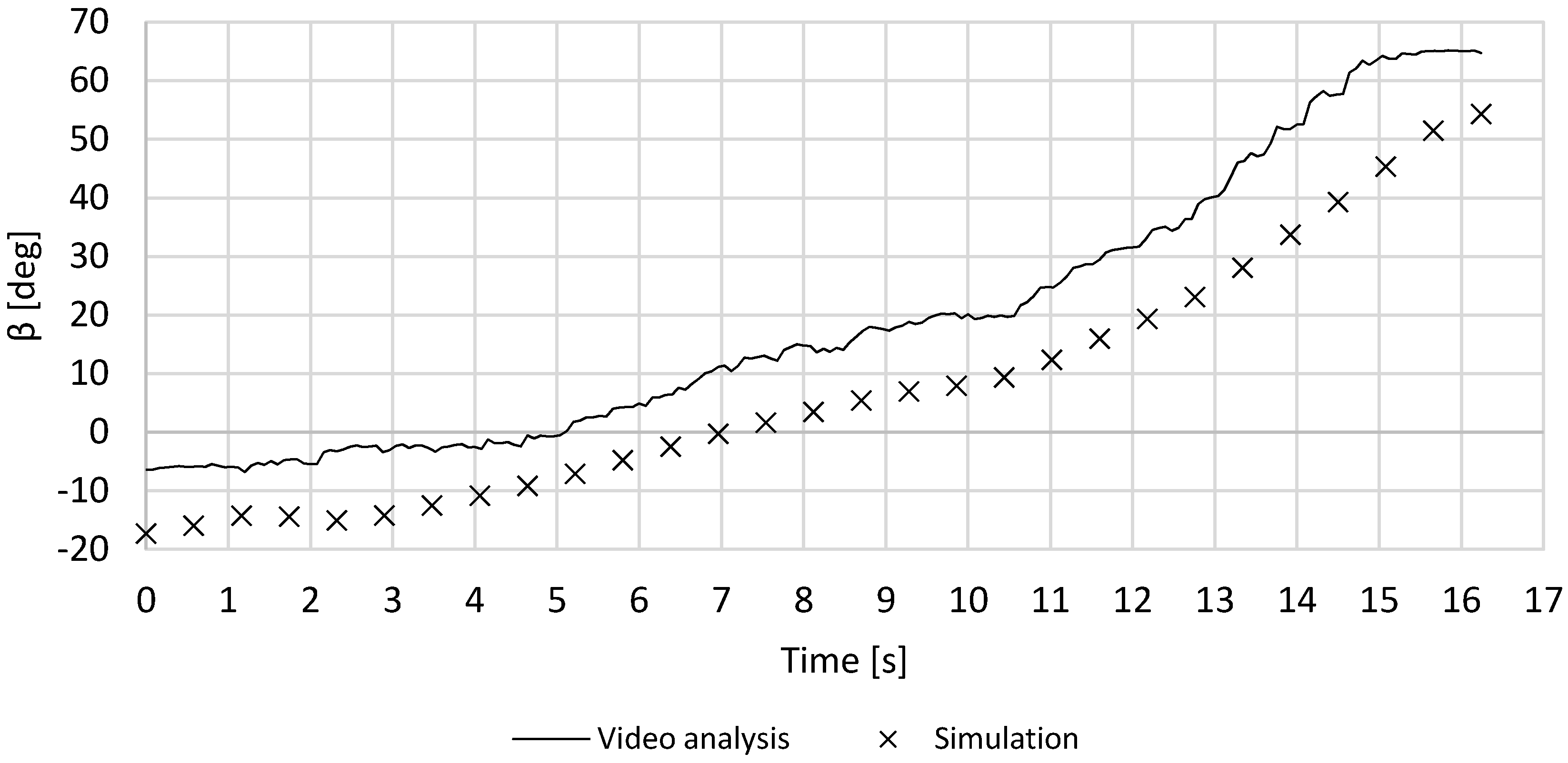
Figure 20 is always below ± 4 deg. This absolute error can be considered suitable as it is exactly within the acceptable error given in the design requirements for the proposed motion assistance application. Similarly, the time history of the β angle is given in
Figure 21 including both simulated and experimentally measured values. The experimentally measured angle β versus time goes from −6.5° to 64.7° in this test. The comparison between the experimentally measured and simulated angle β versus time shows an initial systematic error of 10.8°. If one removes this systematic error, the angular deviation error of angle β versus time is given in
Figure 22. Similarly, a comparison of β from the experimental test and simulation is reported in
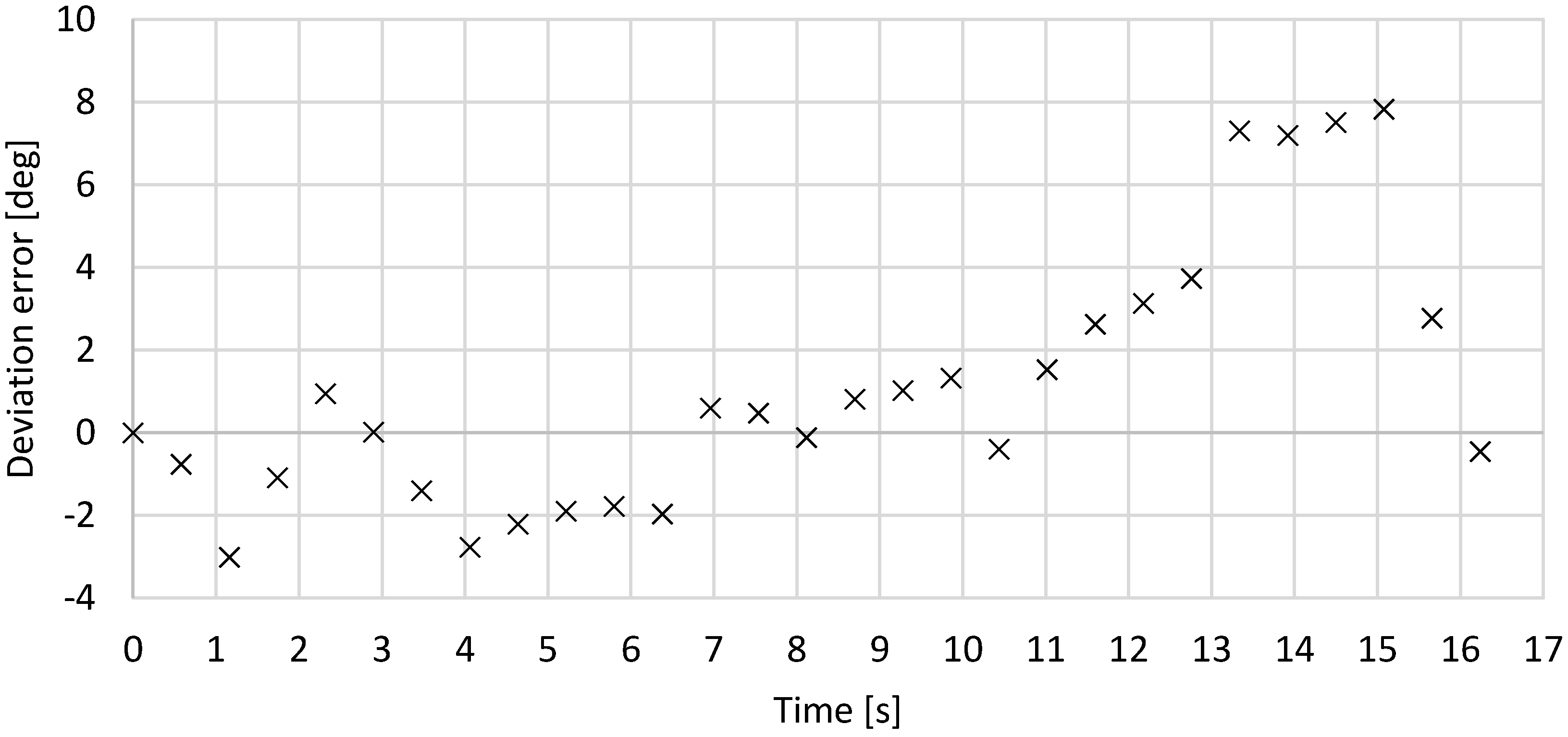
Figure 23, and the computed deviation error of β is reported in
Figure 24. One can note that the absolute error for the angle δ in
Figure 22 is below ± 4° until reaching a critical pose, corresponding to the pose reached after 13 s in the given experiment. Accordingly, operation of the prototype can be considered acceptable within the given design requirements until the closing configuration reaches the critical pose. Further motion needs to be avoided, since it would lead to interference of the human finger with the palm. This limit physically consists of allowing the finger flexion only until the DIP joint is vertically aligned with the MCP joint, referring to the scheme in
Figure 5.
Average angular errors can be computed for each joint deviation error, in terms of as a square root average, as reported in
Table 3. For all angles, the average error remains within the acceptable range of ± 4 degrees as established in the design requirements. This confirms the proposed finger exoskeleton can provide suitable motion assistance to replicate the desired human finger motion trajectory. The error calculation can be affected by the accuracy of the used method for experimentally measured angles via video capture tracking. This can generate non-negligible errors, in particular, if the tracking camera is not properly aligned or calibrated. For this purpose, the camera has been attached to a fixed frame, and the wrist is fixed, so that the exoskeleton movement is kept fixed in a proper plane. Accordingly, main sources of angular error s can be identified in the used 2D video tracking method as well as in joint clearances and backlashes. However, the clearance and backlash aspects can also provide positive features in terms of flexibility and adaptability of the finger exoskeleton motion to a natural finger motion.

 ,
, 


