Abstract
The aim of this paper is to present the results of X-ray diffraction (XRD) tests and scanning electron microscopy-energy dispersive X-ray spectroscopy (SEM-EDS) analyses on a natural and lime-treated clay, in order to determine the percentage of lime able to stabilize soil. For this reason, XRD test analyses have been conducted on natural soil (TQ0) and on two different mixtures (TQ3 and TQ5): The former with 3% and the latter with 5% by mass of quicklime. These mixtures have been analyzed at different curing times: At the addition of lime (0 d), and after a mellowing period of 7 and 28 d. The obtained results show that 3% of CaO is the percentage of quicklime able to modify the material (initial consumption of lime (ICL)) and 5% of CaO is the percentage able to stabilize it (lime stabilization optimum (LSO)). Finally, SEM images allowed for the monitoring of the process of reactions between the soil and lime during the mellowing period, while EDS analyses validated the XRD results in terms of chemical composition of the examined soil. For the examined natural clay, statistical analysis of the obtained EDS results identified a linear regression curve between the added quicklime and the after-treatment Ca content. The proposed approach could be adopted to calculate the content of calcium after the treatment and verify the in situ-added CaO during roadworks or at the end of them.
1. Introduction
The presence of silty and clayey soils is a critical factor not to underestimate during the construction of roads and transport infrastructures in general. This is because their behavior is vulnerable to changes in moistness. Specifically, clays are characterized by a certain activity, which is their capacity of modifying their physical properties and their bearing capacity, depending on the variable water content as a consequence of seasonal water fluctuations [1]. When clayey materials are necessary, lime treatment stabilization allows us to use them. Lime is the stabilizing agent able to improve the strength and stiffness properties of sharply soils, reducing their swell–shrink potential. It causes finely divided clay particles to agglomerate into coarser particles that improve load-bearing properties, and the lime-treated soil hardens by chemical reaction. Lime can be added as calcium oxide (quicklime, CaO) or hydrate lime Ca(OH)2; however, stabilization with quicklime appears more effective than hydrated lime [2]. Its addition to natural soils allows:
- the reduction of the moisture content [3];
- the cation exchange between clay particles and calcium ions of the lime and, thus, the start of the flocculation process, which allows a size distribution change [4];
- the reduction in the plasticity index (PI) through a modification of Atterberg’s limits (i.e., measure of the key values of moisture content of a fine-grained soil: Its shrinkage limit, plastic limit, and liquid limit) [5];
- the development of pozzolanic, cementing, and carbonation reactions [6].
Concerning compaction, there is an increase in the optimum moisture content (OMC) for compaction in situ: Clays are generally moist, and the increased OMC shifts close to the natural moisture content (NMC) [7,8,9].
It is important to know the correct percentage of lime to add, distinguishing between the initial consumption of lime (ICL) and lime stabilization optimum (LSO). These are two specific percentages able to modify and stabilize natural clayey soils, respectively. ICL is the minimum percentage necessary to satisfy the cation exchange reactions [10]: According to the standard ASTM C977-18 [11], it should be at least 1.5% in order to lead the mixture at pH 12.4, when soils are completely modified [12,13]. Percentages of lime above ICL result in pozzolanic reactions: At LSO, the soil reaches the maximum value of unconfined compressive strength. This is due to the formation of hydrate substances that stabilize the material and guarantee the improvement in the mixture’s performance. They are the results of long-term pozzolanic reactions [14]. During this process, strong alkaline conditions (pH = 12.45) induce the silica and alumina of clay minerals to combine together with calcium of the added lime, forming new cementitious products: Calcium silicate hydrates (CSHs), calcium aluminate hydrates (CAHs), and calcium alumino-silicate hydrates (CASHs) [15,16,17]. Laboratory studies of lime-treated soils end with some appraisals about Atterberg’s limits [5], linear swelling, and unconfined compressive strength [18,19]. Finally, appropriate tests during the in situ roadworks need, e.g., the correct value of lime released by the lime-spreader, the water content, the plate loading test, and the density in situ, for the best compaction [20] in order to confirm the laboratory results [21,22].
This paper focuses on the results obtained from X-ray diffraction (XRD) tests and scanning electron microscopy-energy-dispersive X-ray spectroscopy (SEM-EDS) analyses used to investigate physical, chemical, and cementitious changes on lime-soil mixtures. Both methodologies are nondestructive techniques to characterize materials [23,24,25]: XRD provides information on structures, phases, preferred crystal orientations (texture), and other structural parameters, while energy-dispersive X-ray spectroscopy (EDS) works together with SEM to provide qualitative and semi-quantitative results. SEM tests were also used to evaluate microstructural changes in the tested specimens and analyze the effects of quicklime added to the clayey soil.
2. Materials and Methods
The investigated material comes from a clay pit located in Oasi Lipu in Torrile, Italy. Table 1 lists some properties of the natural soil (TQ0); Table 2 lists its particle sieve fraction.

Table 1.
TQ0 properties.

Table 2.
TQ0 particle sieve fraction.
Table 2 lists the TQ0 particle sieve fraction.
Therefore, the chemical and physical characteristics of the natural soil (i.e., Atterberg’s limits and percentage passing at 0.002 mm) allow it to be classified as the group index A7-6 according to the standard ASTM D3282-15 [31]. Adding quicklime with different percentages (3%, 4%, 5%, and 6%), the particle size distribution and the Atterberg’s limits change: The examined soil can be efficacy-stabilized with quicklime. In order to identify the examined materials, in this study, the treated soils are named TQN, where N is the percentage of added quicklime. Given the obtained Atterberg’s limits, not disclosed herein for the sake of brevity, two percentages by mass of quicklime have been considered in this study: 3% and 5%. Regarding TQ0, the first value is ICL; the second value is LSO. Indeed, 5% by mass of quicklime is the highest percentage that improves WL, WP, and IP over time: 6% of quicklime does not improve the soil parameters compared to 5%. The bearing capacity of the treated soil increases with the percentage of quicklime, and 5% of added quicklime ensures the best mechanical performances. The California bearing ratio (i.e., a penetration test that compares the bearing capacity of the examined material with that of a well-graded crushed stone) [30] is 3% for TQ0, 25% for TQ3, 42% for TQ4, and 58% for TQ5. The opposite trend has been observed for swelling (sw) after 4 d imbibition: sw is 1.3% for TQ0, 0.11% for TQ3, 0.07% for TQ4, and 0.017% for TQ5. According to the modified Proctor test [32], Figure 1 shows the relationship between the achievable dry bulk density and the moisture content (w). The added lime results in flatter compaction curves: The optimum moisture content increases with the stabilizer content and the maximum dry density decreases as the percentage of lime increases: This result complies with the expected effects of the stabilization treatment. Indeed, lime stabilization of fine-grained soils results in a load-bearing capacity increase and swelling and shrinkage potential decrease [33]. Therefore, a stabilized soil has higher strength, lower permeability, and lower compressibility than the native soil.
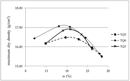
Figure 1.
Comparison of compaction curves.
TQ0, TQ3, and TQ5 samples have been analyzed. Before the XRD tests [34], the specimens have been dried in an oven at 40 °C for 72 h in order to minimize the sensibility of clayey non-treated minerals to strong temperature ranges that change the properties of clay [35]. However, not all sources in the literature declare the need for drying the treated specimens in an oven at 40 °C for 72 h. At this purpose, the authors compared diffractograms of TQ3 before and after drying in order to verify the effect of moisture on the XRD results: No significant differences in terms of peak intensity and position have been found. The only detectable difference concerns a greater definition of the peaks, which are more detectable from the background noise. However, it has a very slight diversity: For this reason, diffraction patterns of samples stove-dried at 40 °C will be referenced. After drying and quartering, the material was packed in a powder mount, against glass, to provide a stable surface for analysis. TQ3 and TQ5 have been analyzed at different curing times: 0, 7, and 28 mellowing days. In order to correctly interpret the results from XRD tests, the added quicklime has been tested with XRD. Moreover, SEM-EDS analyses investigated both morphology and microstructures of the treated materials at 0, 7, and 28 mellowing days. Indeed, SEM/EDS is a widely applied elemental microanalysis method capable of identifying all elements in the periodic table and quantifying all elements except light elements up to Li [36].
The instruments used in this study are:
- For the XRD tests: Philips X’Pert Pro PANalytical diffractometer, with Cu-Kα = 1.5406 Å radiation, equipped with X’Pert HighScore software. The obtained diffractograms were analyzed through Powder Cell 2.4 software. The XRD test conditions were:
- Incident beam path (radius): 240 mm
- Diffracted beam path (radius): 240 mm
- Diffracted Soller slit: 0.04 rad
- Diffracted monochromator: For Cu
- Prog receiving slit: 0.02°
- Used wavelength (Cu): 1.5405980 Å
- Angular range: θmin = 5° and θmax = 90°;
- Step size (2θ): 0.02°;
- Counting time per step: 1 s;
- Excitation: 40 kV, 40 mA.
- For the SEM-EDS analyses: The electron scanning microscope Hitachi S-2500. The adopted test conditions for SEM-EDS analyses were:
- Excitation voltage of the tungsten filament of 25 kV;
- Magnification: 500X and 1000X;
- Detector: Si(Li)-type detector
- Resolution energy: 140 eV. It was defined by the full-width at half-maximum (FWHM) resolution of the Mn Kα X-ray peak at 5.890 keV.
3. Results
3.1. XRD Analyses
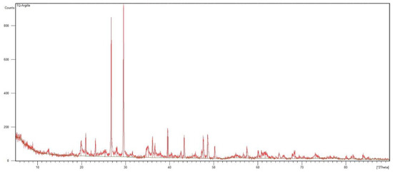
Figure 2.
XRD pattern of TQ0.

Table 3.
XRD results of TQ0.
The peaks in the diffractogram prove the compositional richness of the specimen [37]. X’Pert HighScore allowed the identification of the main mineral phases:
- Quartz (Q), its chemical formula is SiO2;
- Calcite (CA), its chemical formula is CaCO3;
- Illite (I), its chemical formula is K0.88Al2[Al0.88Si3.12O10](OH)2
- Kaolinite (K), its chemical formula is Al2Si2O5(OH)4;
- Chlorite-serpentine (CH), its chemical formula is (Mg,Al )6(Si,Al )4O10 (OH)8.
The diffractogram of TQ0 (Figure 2) has been overlaid with the diffractogram of each identified mineral phase in order to complete the analysis. According to Table 3, Figure 3a–c present the XRD patterns of TQ0 and assign the identified mineral phases to peaks in Figure 2. In order to ensure readability, the x-axis of the XRD pattern of TQ0 has been divided into three subsections (2θ is 5°–33° in Figure 3a, 33°–53° in Figure 3b, and 53°–90° in Figure 3c).
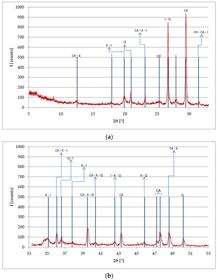
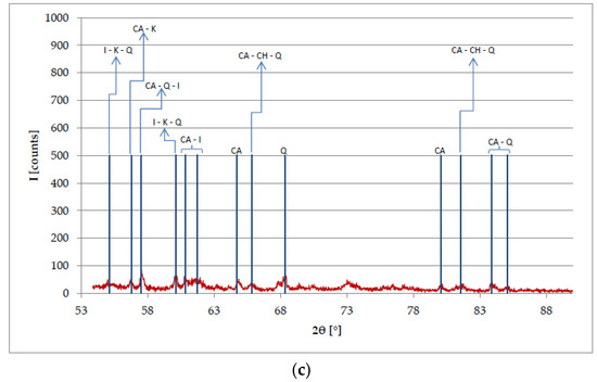
Figure 3.
Attribution of the identified mineral phases in Table 3 to peaks of the TQ0 diffractogram: (a) 2θ is 5°–33°; (b) 2θ is 33°–53°; (c) 2θ is 53°–90°.
In Figure 3, the peak at 2θ = 73.0683° is caused by a different phase (i.e., Amesite): It is a mineral with general formula Mg2Al2SiO5(OH)4.
In Figure 4, the XRD pattern of the used quicklime (black curve) is overlaid on that of CaO (red curve). The highest peaks of the used quicklime coincide with those of CaO; however, some peaks are caused by the mineralogical phases of calcite (CaCO3) and calcium hydroxide (Ca(OH)2). In Figure 4, the green circles highlight the differences between the overlaid patterns: The blue ones are related to CaCO3 (2θ equal to 23° and 29°), and the red ones are related to Ca(OH)2 (2θ equal to 18° and 34°).
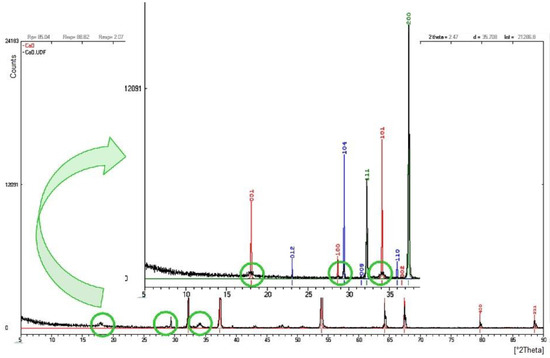
Figure 4.
Differences between the quicklime diffractogram (black curve) and the CaO diffractogram (red curve).
The XRD analysis on the treated soil complies with the procedures exposed for TQ0. During the mellow period, the specimens were in airtight containers at room temperature and away from direct sunlight in order to preserve the state conditions and avoid the quicklime carbonation. Diffraction spectra of TQ3 and TQ5 overlaid on the TQ0 diffractogram are shown in Figure 5 and Figure 6, respectively. In both figures, the XRD pattern of TQ0 is red and those of the treated soils are blue, while the green circles highlight the new peaks, which are related to the added quicklime. The highlighted new peaks demonstrate the effective addition of the treatment agent.
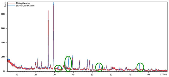
Figure 5.
TQ3 diffractogram at day 0 (blue) overlaid on that of TQ0 (red).
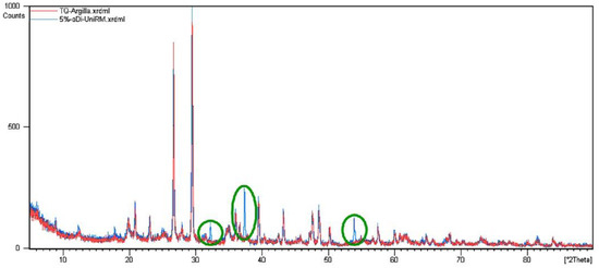
Figure 6.
TQ5 diffractogram at day 0 (blue) overlaid on that of TQ0 (red).
Overlaying the XRD diffractogram of TQ0 (Figure 2) on that of TQ3 after the 7 d mellowing period (Figure 7), it is possible to observe the beginning of some changes (green circles in Figure 7).
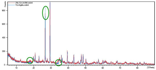
Figure 7.
Overlay of TQ3 diffractogram at day 7 (red) and TQ0 diffractogram (blue).
The most significant changes are related to three angular positions: 2θ = 17.7856° (peak magnification), 2θ = 34.9596° (peak magnification to the left), and 2θ = 26.7273° (peak intensity reduction). These results demonstrate that the added quicklime caused positive results: Peak intensity reduction produced by clay minerals and changes in the 2θ range between 20° and 35°, which is the typical diffraction range of CASH [38]. It demonstrates the on-going process of the lithosynthesis process: After 7 d curing, new aggregate structures are present in the treated soil.
Figure 8 shows the X-ray diffraction pattern of the 7 d mellowed TQ5 (blue curve) overlaid on the diffractogram of TQ (red curve) (Figure 2).
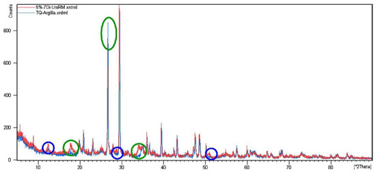
Figure 8.
Overlay of 7 d TQ5 diffractogram (red) and TQ0 diffractogram (blue).
The green circles in Figure 8 highlight the changes observed at day 7 in TQ3 (Figure 7): In TQ5, the differences regarding higher or lower peak intensity are higher than those in TQ3. Moreover, in Figure 8, the blue circles highlight the new variations. Three main changes are identifiable:
- 2θ = 17.7856° shows a local enlargement of the diffraction peak;
- at 2θ = 34.9596°, the peak height is slowly reduced and is shifted toward lower diffraction angles. This modification indicates the presence of traces of Portlandite;
- at 2θ = 26.7273°, the peak height is reduced.
Therefore, the added quicklime modified TQ0 at the 7 d mellowing period because the observed modifications involve a reduction of clayey minerals (i.e., reduced peak of I at 2θ = 26.7273°) and the observed peaks are between 2θ = 20° and 35°. This range is typical of CASH, from which both CSH and CAH are derived. CSH and CAH are reaction products with needle-like structures that provide strength to the material and guarantee the connection between the clay particles.
The overlay of XRD patterns of TQ0 (Figure 2) and TQ3 at the 28 d mellowing period is shown in Figure 9.
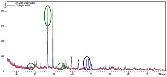
Figure 9.
Overlay of TQ3 diffractogram at 28 d (red) and TQ0 diffractogram (blue).
It is possible to verify that the changes observed at 7 d have continued over time. With regard to the 7 d XRD pattern of TQ3 (Figure 7), the main changes are:
- at 2θ = 17.7856°, the peak height is greater;
- at 2θ = 34.9596°, the peak is widened;
- at 2θ = 26.7273°, the peak height is still reduced.
The three typical diffraction peaks of calcite (2θ = 43°, 47°, and 48°) are highlighted in blue: In TQ3, they show greater intensity than those in the TQ0 diffractogram (Figure 2). This is due to the carbonation of the added CaO caused by the chemical reaction with CO2 (Equation (1)): The reaction product CaCO3 binds the soil grains.
CaO + CO2 → CaCO3
At the 28 d treatment period, TQ5 had the X-ray diffraction pattern shown in Figure 10 (red curve); the blue curve in Figure 10 refers to TQ0.
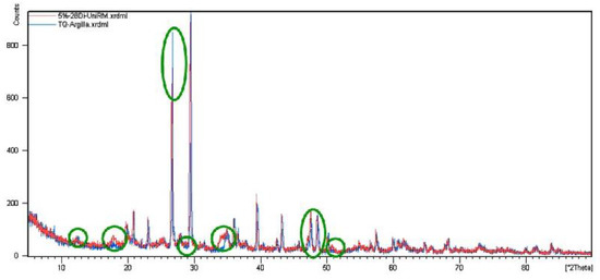
Figure 10.
Overlay of TQ5 diffractogram at 28 d (red) and TQ0 diffractogram (blue).
However, the observed changes in Figure 10 are not related to new formations: The high percentage of quartz in TQ0 slows down reactions between soil and lime and inhibits the total crystallization of CASH into CSH and CAH. Moreover, the presence of calcite, both natural and resulting from the carbonation of calcium, cannot be overlooked. It can form comparatively weak cementing agents such as calcium carbonate, and this reaction is undesirable because it exhausts some lime that would normally be used to form more resistant cementitious products [39,40].
3.2. SEM-EDS Analyses
The results of SEM-EDS analyses permit images of samples in grayscale (Figure 11 and Figure 12) and quantitative microanalyses (Figure 13, Figure 14 and Figure 15) to be obtained. Figure 11a,d show SEM images of TQ0 at 500X and 1000X magnification, respectively; Figure 11b,e show SEM images of TQ3 at 500X and 1000X magnification after a 28 d mellowing period, respectively; Figure 11c,f show SEM images of TQ5 at 500X and 1000X magnification, after a 28 d mellowing period, respectively.
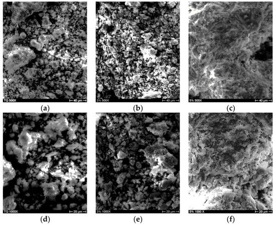
Figure 11.
SEM images of (a) TQ0—500X; (b) TQ3 at 28 d mellowing period—500X; (c) TQ5 at 28 d mellowing period—500X; (d) TQ0—1000X; (e) TQ3 at 28 d mellowing period—1000X; (f) TQ5 at 28 d mellowing period—1000X.
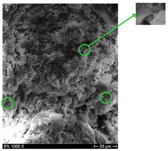
Figure 12.
TQ5 at 28 d mellowing period—1000X.
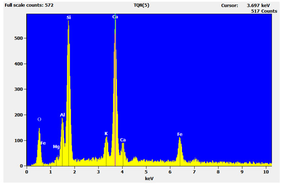
Figure 13.
EDS spectrum of TQ0.
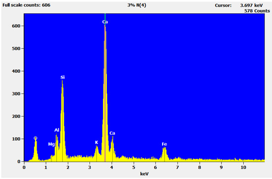
Figure 14.
EDS spectrum of TQ3 at 28 d.
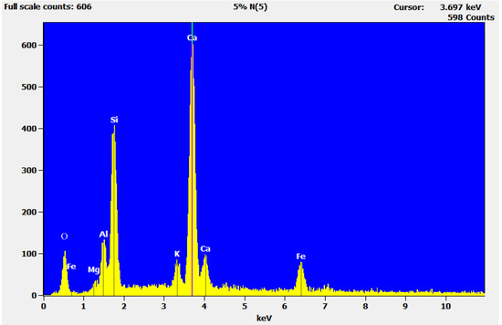
Figure 15.
EDS spectrum of TQ5 at 28 d.
The morphology of TQ0 (Figure 11a,d) is characterized by bound-together grains: The natural soil is composed of agglomerations devoid of hydrate compounds, which could give compactness and strength. TQ3 does not have a very coherent surface (Figure 11b); according to the 1000X magnification (Figure 11e), it presents the formation of agglomerates of larger material, but acicular structures that bind them together are still absent. The morphology of TQ5 (Figure 11c,f) seriously differs from those of the TQ0 and TQ3 SEM images. It appears more compact and uniform than TQ3 and has larger grains: The smaller particles have joined the others over time. The magnification 1000X of TQ5 (Figure 12) shows beginnings of needle-like structures, which join grains one to each other (green circles); the magnified image in Figure 12 shows an acicular structure. It demonstrates the capacity of 5% of CaO to stabilize the examined natural soil.
The peak without chemical element in Figure 13 is attributable to iron (7 keV).
The comparison between spectra in Figure 13 and Figure 14 highlights the reduction of peaks attributable to the clayey fraction (i.e., Al, Si, K). It confirms the diffraction peak intensity reduction observed at 2θ = 26.7273°.
The comparison between spectra in Figure 13 and Figure 15 highlights the percentage variation of the chemical elements and confirms the trend due to stabilization observed in Figure 14. Table 4 lists the microanalysis results for TQ0, TQ3, and TQ5 at the 28 d mellowing period.

Table 4.
TQ0, TQ3, and TQ5 28 d microanalysis.
In all the samples, there is a big presence of silicon and calcium, the first due to the clay matrix and quartz contained in the natural soil. In addition, Al, Mg, and K can be related to the clayey matrix. After the 28 d mellowing period, significant quantity changes have happened and the reduction trend of the chemical elements addressable to the clay sample fraction (i.e., Al, Si, and K) is evident (Table 4). These results comply with the XRD analyses (i.e., the reduction of the diffraction peak at 2θ = 26.7273° related to the mineral phases of I and Q). Moreover, a progressive increase in calcium is also clear. In TQ0, a massive calcium presence was found (35.99%), due to the natural composition of the specimen, while its increase in TQ3 and TQ5 (46.38% and 50.52%, respectively) is imputed to the added lime.
Finally, the authors carried out experimental SEM-EDS tests on different samples varying the percentage of the added CaO. After a 24 h mellowing period, seven soils (i.e., TQ0, TQ1, TQ2, TQ3, TQ5, TQ6.5, and TQ) were investigated with 16 specimens each. In order to prepare specimens of treated soil, 40 g of TQ0 was taken and dried in an oven at 40 °C for 72 h to eliminate the moisture in the natural soil (and to avoid damage to the EDS objective lens in the sample chamber). After addition of N by mass percentage of CaO, the treated soil mellowed during 24 h before EDS analysis. The adopted test conditions for SEM-EDS analyses were: Excitation voltage of the tungsten equal to 25 kV; working distance equal to 35 mm; magnification: 100X. From each specimen, five measures of Ca (and other chemical elements) content were obtained. The obtained results were filtered by box plot analysis according to the following procedures:
- division of observations into quartiles;
- identification and deletion of outlier values (more than 3/2 times of upper quartile or less than 3/2 times of lower quartiles);
- identification of the superior and inferior adjacent values (i.e., greatest and lowest values excluding outliers, respectively);
- calculation of the average using admissible values.
Figure 16 shows the average values of the after-treatment Ca content vs. the added quicklime percentages; the regression linear curve has a coefficient of determination equal to 0.9841.
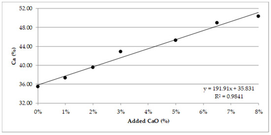
Figure 16.
After-treatment Ca content vs. added quicklime.
Table 5 shows the absolute error (Equation (2)), average, maximum, and minimum values obtained from EDS analyses for the examined TQN specimens
where er is the absolute error and CaTQN is the Ca content calculated for 16 specimens with N percentage of added quicklime.
er = (max (CaTQN) − min (CaTQN))/2

Table 5.
EDS analyses of Ca contents on natural soil and treated specimens.
With regard to the investigated N values, Table 5 shows that the ranges of variation of Ca content are not overlapping: The proposed method could be valid for the declared goal of the study. However, a limit in the obtained results should be observed: According to Table 5, the intervals of TQ3 and TQ5 are disjointed because the maximum Ca content for TQ3 (i.e., 44.36) is lower than the minimum for TQ5 (i.e., 44.55), but the difference is small if compared to the absolute errors, as it could lead to an overlap of variability ranges with that of TQ4. The anomaly of this result requires further investigations for a practical application of the proposed method.
4. Conclusions
When a lime treatment of soil is carried out, it is necessary to verify if the roadworks comply with the procedures defined during design and laboratory tests. Therefore, the calcium content as consequence of the added CaO could be useful to monitor the treatment works. Three goals should be pursued in order to define a parameter and the method to calculate it: Rapid procedure of evaluation, method suitable for before/after analysis, and bi-univocal correspondence between the CaO content and the identified parameter. Due to their execution rapidity, XRD tests and SEM-EDS analyses have been conducted on a clayey natural and treated soil. X-ray diffraction (XRD) is a powerful nondestructive technique for characterizing crystalline materials. It provides information on structures, phases, preferred crystal orientations (texture), and other structural parameters, such as average grain size, crystallinity, strain, and crystal defects. XRD tests on TQ0 allowed the identification of its composition: Its mineralogical phases are calcite, illite, quartz, kaolinite, and chlorite-serpentine mixed layer. XRD tests at 7 and 28 d mellow periods on TQ3 and TQ5 were used to verify the successful addition of the stabilizing element, through intensity variation and the “birth” of new diffraction peaks (i.e., mineralogical phases). These tests allowed the development of chemical reactions in the treated soils to be monitored over time and to verify a qualitative difference between the addition of 3% and 5% of quicklime. Therefore, for the examined natural soil, the first percentage could be considered the percentage able to improve the mixture (ICL) and the second one the quantity able to stabilize it (LSO).
EDS analyses allowed the hypothesis of the chemical composition of the samples studied through XRD tests to be validated, while SEM images allowed the maturation of the stabilized mixture to be investigated, identifying the formation of acicular structures responsible for the performance improvement. They confirmed 5% of CaO as the percentage of quicklime that stabilizes the natural soil. On the other hand, the EDS spectra allowed us to obtain the values of Ca content for different percentages of added quicklime: 16 specimens have been examined for each considered percentage of added quicklime between 0% and 8%. A linear regression curve between added CaO and after-treatment Ca content was obtained: It has a high coefficient of determination (i.e., 0.9805) that confirms the statistical reliability of the proposed approach to evaluate the increase in calcium content due to the added quicklime.
However, further studies with SEM-EDS analyses should be carried out on different treated soils, before and after the quicklime addition, to define a reliable method (e.g., number of specimens to analyze, procedure to prepare specimens, definition of range of application). Indeed, after a preliminary laboratory analysis to identify the linear regression curve between Ca and CaO, the EDS results on the in situ-treated soil could allow verification of the added CaO.
Author Contributions
Conceptualization, L.M. and A.D.; Data curation, L.M., A.T. and A.D.; Formal analysis, A.T.; Investigation, A.T.; Methodology, S.N.; Project administration, A.D.; Supervision, L.M.; Validation, S.N.; Visualization, L.M.; Writing—original draft, L.M. and A.T.; Writing—review & editing, L.M. All authors have read and agreed to the published version of the manuscript.
Funding
This research received no external funding.
Acknowledgments
The authors thank Eng. Franco Bernardini and Eng. Corrado Zanichelli and acknowledge their support to develop this study.
Conflicts of Interest
The authors declare no conflict of interest.
References
- Adem, H.H.; Vanapalli, S.K. Review of methods for predicting in situ volume change movement of expansive soil over time. J. Rock Mech. Geotech. Eng. 2015, 7, 73–86. [Google Scholar] [CrossRef]
- Bell, F.G. Engineering Treatment of Soils; E&FN Spon Imprint of the Taylor&Francis Group: London, UK, 1993. [Google Scholar]
- Olinic, T.; Olinic, E. The Effect of Quicklime Stabilization on Soil Properties. Agric. Agric. Sci. Procedia 2016, 10, 444–451. [Google Scholar] [CrossRef]
- Praticò, F.G.; Puppala, A.J. Lime and Cement Treatments of Subgrades in Southern Italy: Facing Interports Issues and Challenges. Procedia Soc. Behav. Sci. 2012, 53, 389–398. [Google Scholar] [CrossRef]
- Rao, S.; Shivananda, P. Role of curing temperature in progress of lime-soil reactions. Geotech. Geol. Eng. 2005, 23, 79–85. [Google Scholar] [CrossRef]
- Haas, S.; Ritter, H.-J. Soil improvement with quicklime—Long-time behaviour and carbonation. Road Mater. Pavement Des. 2019, 20, 1941–1951. [Google Scholar] [CrossRef]
- Balasubramaniam, A.S.; Bergado, D.T.; Buensuceso, B.R.; Yang, W.C. Strength and deformation characteristics of lime-treated soft clays. Geotech. Eng. 1989, 20, 49–65. [Google Scholar]
- Bell, F.G. Lime stabilization of clay minerals and soils. Eng. Geol. 1996, 42, 223–236. [Google Scholar] [CrossRef]
- Muhmed, A.; Wanatowski, D. Effect of Lime Stabilisation on the Strength and Microstructure of Clay. J. Mech. Civ. Eng. 2013, 6, 87–94. [Google Scholar]
- Bhuvaneshwari, S.; Robinson, R.G.; Gandhi, S.R. Resilient Modulus of Lime Treated Expansive Soil. Geotech. Geol. Eng. 2018, 37, 305–315. [Google Scholar] [CrossRef]
- American Society for Testing and Materials International (ASTM). ASTM C977-18. Standard Specification for Quicklime and Hydrated Lime for Soil Stabilization; ASTM International: West Conshohocken, PA, USA, 2018. [Google Scholar]
- Eades, J.L.; Grim, R.E. A Quick Test to Determine Lime Requirements for Lime Stabilization; Highway Research Board, National Research Council: Washington DC, USA, 1966; Volume 139, pp. 61–72. [Google Scholar]
- American Society for Testing and Materials International (ASTM). ASTM D 6276-99a. Standard Test Method for using pH to Estimate the Soil Lime Proportion Requirement for Soil Stabilization; ASTM International: West Conshohocken, PA, USA, 1999. [Google Scholar]
- Rosone, M.; Megna, B.; Celauro, C. Analysis of the chemical and microstructural modifications effects on the hydro-mechanical behaviour of a lime-treated clay. Int. J. Geotech. Eng. 2019, 1–14. [Google Scholar] [CrossRef]
- Al-Mukhtar, M.; Khattab, S.; Alcover, J.-F. Microstructure and geotechnical properties of lime-treated expansive clayey soil. Eng. Geol. 2012, 139–140, 17–27. [Google Scholar] [CrossRef]
- Bhuvaneshwari, S.; Gandhi, S.R.; Robinson, R.G. Behaviour of Lime Treated Cured Expansive Soil Composites. Indian Geotech. J. 2014, 44, 278–293. [Google Scholar] [CrossRef]
- Eades, J.L.; Grim, R.E. Reaction of Hydrated Lime with Pure Clay Minerals in Soil Stabilization. Highw. Res. Board Bull. 1960, 262, 51–63. [Google Scholar]
- European Committee for Standardization (EN). EN 13286-47:2012. Unbound and Hydraulically Bound Mixtures—Part 47: Test Method for the Determination of California Bearing Ratio, Immediate Bearing Index and Linear Swelling; European Committee for Standardization: Brussels, Belgium, 2012. [Google Scholar]
- EN ISO 17892-7. Geotechnical Investigation and Testing—Laboratory Testing of Soil—Part 7: Unconfined Compression test (ISO 17892-7:2017). 2017. Available online: https://www.iso.org/standard/70789.html (accessed on 21 January 2020).
- Firoozi, A.; Olgun, G.; Firoozi, A.A.; Baghini, M.S. Fundamentals of soil stabilization. Geo-Eng. 2017, 8, 26. [Google Scholar] [CrossRef]
- Zhao, H.; Liu, J.; Guo, J.; Zhao, C.; Bi-weo, G. Reexamination of Lime Stabilization Mechanisms of Expansive Clay. J. Mater. Civ. Eng. 2015, 27, 1–7. [Google Scholar] [CrossRef]
- Moretti, L.; Conficconi, M.; Natali, S.; D’Andrea, A. Statistical analyses of SEM-EDS results to predict the quantity of added quicklime in a treated clayey soil. Constr. Build. Mater. 2020. accepted paper. [Google Scholar]
- Bunaciu, A.A.; Udriştioiu, E.G.; Aboul-Enein, H.Y. X-Ray Diffraction: Instrumentation and Applications. Crit. Rev. Anal. Chem. 2015, 45:4, 289–299. [Google Scholar] [CrossRef]
- Das, R.; Eaqub, A.; Hamid, A.; Bee, S. Current applications of x-ray powder diffraction—A review. Rev. Adv. Mater. Sci. 2014, 38, 95–109. [Google Scholar]
- Mohammed, A.; Abdullah, A. Scanning Electron Microscopy (SEM): A Review. In Proceedings of the 2018 International Conference on Hydraulics and Pneumatics, Băile Govora, Romania, 7–9 November 2018, ISSN 1454-8003. [Google Scholar]
- American Association of State Highway and Transportation Officials (AASHTO). AASHTO T89: Standard Method of Test for Determining the Liquid Limit of Soils; American Association of State Highway and Transportation Officials: Washington, DC, USA, 2013. [Google Scholar]
- American Association of State Highway and Transportation Officials (AASHTO). AASHTO T90: Standard Method of Test for Determining the Plastic Limit and Plasticity Index of Soils; American Association of State Highway and Transportation Officials: Washington, DC, USA, 2016. [Google Scholar]
- American Society for Testing and Materials International (ASTM). ASTM D2216. Standard Test Methods for Laboratory Determination of Water (Moisture) Content of Soil and Rock by Mass; ASTM International: West Conshohocken, PA, USA, 2019. [Google Scholar]
- European Committee for Standardization (EN). EN 1744-1:2009+A1:2012. Tests for Chemical Properties of Aggregates—Part 1: Chemical Analysis; European Committee for Standardization: Brussels, Belgium, 2012. [Google Scholar]
- American Society for Testing and Materials International (ASTM). ASTM C837-09, Standard Test Method for Methylene Blue Index of Clay; ASTM International: West Conshohocken, PA, USA, 2019. [Google Scholar]
- American Society for Testing and Materials International (ASTM). ASTM D3282-15 Standard Practice for Classification of Soils and Soil-Aggregate Mixtures for Highway Construction Purposes; ASTM International: West Conshohocken, PA, USA, 2015. [Google Scholar]
- American Society for Testing and Materials International (ASTM). ASTM D1557-12e1 Standard Test Methods for Laboratory Compaction Characteristics of Soil Using Modified Effort; ASTM International: West Conshohocken, PA, USA, 2012. [Google Scholar]
- Diamond, S.; Kinter, E.B. Mechanism of Soil-Lime Stabilization. Highw. Res. Rec. 1965, 92, 83–102. [Google Scholar]
- Khale, M.; Kleber, M.; Jahn, R. Review of XRD-based quantitative analyses of clay minerals in soils: The suitability of mineral intensity factors. Geoderma 2002, 109, 191–205. [Google Scholar] [CrossRef]
- Moritz, L.; Gabrielsson, A. Temperature Effect on the Properties of Clay. Geotech. Spec. Publ. 2001, 112, 304–314. [Google Scholar]
- Newbury, D.E.; Ritchie, N.W.M. Is Scanning Electron Microscopy/Energy Dispersive X-ray Spectrometry (SEM/EDS) Quantitative? Scanning 2012, 35, 141–168. [Google Scholar] [CrossRef] [PubMed]
- Ameh, E.S. A review of basic crystallography and x-ray diffraction applications. Int. J. Adv. Manuf. Technol. 2019, 105, 3289–3302. [Google Scholar] [CrossRef]
- Musta, B.; Kassim, K.A.; Salim, R.M. Mineralogical development in a lime treated clayey sand soil. In Proceedings of the Geological Society of Malaysia Annual Geological Conference, Pangkor Island, Perak Darul Ridzuan, Malaysia, 2–3 June 2001. [Google Scholar]
- Saeed, K.A.S.; Kassim, K.A.; Yunus, M.N.Z. Characterization of Hydrated Lime-Stabilized Brown Kaolin Clay. Int. J. Eng. Res. Technol. 2013, 2, 3722–3727. [Google Scholar]
- Kassim, K.A.; Chern, K.K. Lime stabilized Malaysian cohesive soils. Malays. J. Civ. Eng. 2004, 16, 13–24. [Google Scholar]
© 2020 by the authors. Licensee MDPI, Basel, Switzerland. This article is an open access article distributed under the terms and conditions of the Creative Commons Attribution (CC BY) license (http://creativecommons.org/licenses/by/4.0/).