Article

Prediction of Cutting Parameters of HVOF-Sprayed Stellite 6

1
Regional Technology Institute, Faculty of Mechanical Engineering, University of West Bohemia, Univerzitni 8, 306 14 Pilsen, Czech Republic
2
Department of Machining and Manufacturing Technology, Faculty of Mechanical Engineering, University of Zilina, Univerzitná 1, 010 26 Zilina, Slovakia
3
PLASMAMETAL, spol. s r.o., Tovární 917/1e, 643 00 Brno-Chrlice, Czech Republic
*
Author to whom correspondence should be addressed.
Appl. Sci. 2020, 10(7), 2524; https://doi.org/10.3390/app10072524
Submission received: 18 March 2020 / Revised: 30 March 2020 / Accepted: 2 April 2020 / Published: 6 April 2020

Abstract

:
In this research, the authors set out to propose a new method of predicting and adjusting the main cutting parameters of chip machining, namely spraying on the substrate. In the experiments, a total of 28 turning cuts on a Stellite 6 coating layer were realized. The base materials of the Stellite 6 layers were EN S235JRG1 and carbide WC-Co. This work aimed to find out and optimize the influence of different combinations of cutting parameters. Due to the coating solution, the work is focused on the evaluation of the roughness Ra (μm) of the turned substrate, the grain size Dgr (μm) of the spraying, the normal stress σrz (MPa), the residual stress σrez (MPa), the specific cutting force Fc (N), the quality of adhesion to the substrate Adhmp (MPa) and other parameters. For the sake of a comprehensive solution to the problem, several new predictive equations and subsequent suggestions for solutions have been derived from this research topic based on the newly obtained experimental results. The proposed models and procedures make it possible to get new results and insights into coating technologies.

1. Introduction

Classical or conventional machining is a process of removing material in the form of chips by direct contact between the tool and workpiece. It depends what kind of machining process is used, but generally, the tool penetrates into the workpiece to a certain depth, while the workpiece or tool provide suitable motion. Tools have a specific number of cutting edges of known geometry. During machining the workpiece is subjected to shear, compression and also bending and not only the surface of the material is altered but also below it. The process of material removal puts very high demands on surface quality.
The topography of the machined surface has a significant effect on its function and must be taken into account for the setup of machining conditions. The machining behaviours of materials differ from each other. The rapid evolution of material development has had a direct impact on the development of new machining technologies. High-speed machining technologies represent an effective way to increase productivity. The productivity of any such process is limited by the machinability of the material. Material properties consequently affect machining behaviour. Cobalt–chromium alloys are some of the most difficult materials to machine [1]. The properties which make them very attractive in the industry include high strength and hardness at high temperatures and corrosion resistance. Usually, the problems with the machining of these materials concern the cutting speed and feed, as they have a very narrow recommended application range for good results.
If the cutting speed is too low, the material sticks to the cutting edge, and if it is too high, abrasive wears occurs on the cutting edge. The development of Stellite played a particularly important role in metal cutting after the first use of tungsten steel and high-speed steel in the 19th century. The Stellite alloy was invented in 1900 by American metallurgist Haymer E. Haynes as a substitute for silver. In 1907, the Deloro Smelting and Refining company was founded by M. J. O’Brien and E. Haynes in the village of Deloro (Ontario, Canada). When Haynes in 1912 focused on nickel-based components, O’Brien founded the Deloro Stellite company for the production of cobalt-based alloys. There is a slight difference in the composition of the Stellite alloys. Stellite 6 is one of the most popular among them and is suitable, for example, for press forging. The higher carbon alloys (Stellite 6K and Stellite 6B) are used for abrasion, or severe galling and are more difficult to machine than lower carbon alloys. The lower carbon alloys are often used for sliding wear or cavitation. Shape and size of the carbides are dependent on the cooling rate, and an increase of carbides reduces ductility [2,3,4,5,6].
Stellite 6 is a popular alloy that has several industrial applications, therefore, machining this superalloy has been a subject of intense engineering research because of the need to determine the best machining tool to forge, cast, cut, and finished industrial products.
Some surfaces are sprayed with Stellite 6, and machining such surfaces requires experience and skill in order to achieve the required results for commercial applications. Experiments have been done to identify the cutting tool surface and physio-mechanical properties that can ensure that Stellite 6 is properly machined [7,8,9,10]. While such studies have yielded good results, no consensus has been reached that can point to the right type of tool to machine Stellite 6. Therefore, further research has to be done in order to ensure that the tip wear of the alloy is improved. Stellite 6 is used to build-up surfaces that are subjected to intense wear and can be used in a welded or sprayed form. Most of the recent studies have focused on the evaluation of Stellite-6 coatings with regards to the following aspects: microstructure [11,12,13], chemical compositions, mechanical properties, tribological characteristics [14], or residual stress distribution [15].
Although there are some data on machining Stellite alloys, the available information is still very limited; in particular, information about the adhesion on a substrate or the adhesive forces of the applied material on the substrate were not studied systematically. The surface roughness, along with other parameters of the topography of machined surfaces [16], is of crucial importance to the specificity of coatings technologies [17,18,19,20]. That is why the authors decided to devote deeper attention to this topic in this paper. Because the authors have been dealing with the final surface topography generated by various technologies for a long time, they have new results to try to apply [21,22,23,24,25]. Our study will be mainly analytical, examining the exact definition and discrete evaluation of the influence of different combinations of main cutting parameters and analogously each of the parameters separately on the final topography of the surface, especially in terms of good adhesion and solid adhesion. These questions and their solutions are covered by the relevant sections below.
The paper presents an original method for determination of the main stress-deformation functions and processes, the generation of adhesive forces and the stress between the turned substrate and the coating. Thus, the mechanical and adhesive processes involved in chip formation interact with the machining tool, the final surface condition, and the generation of bonding forces between the turned substrate material and the coating material. A new equation for mechanical equilibrium is derived in stress-strain processes that occur during chip formation. The newly derived equilibrium equation for chip machining enables the acquisition of new exact knowledge and the necessary data. The monitored parameters are analysed on three mechanically different materials. It is a measurement and analytical processing of changes in the continuous and resulting values of the parameters in the cut, taking into account the assumption of subsequent application of the coating layer.

2. The Methodology of the Work

The experiments are based on different combinations of three cutting parameters, namely speed vc (m∙min−1), feed f (mm) and depth of cut ap (mm). For the sake of completeness, we have included a fourth, the influence of tool back angle λ (°), but in the following analysis, we include only the first three parameters. We consider these to be basic because they directly create the machined volume of the material, the structure and texture of the machined surface, as well as its instantaneous stress-strain state. There were 28 sessions in each combination. Parameter combinations are freely selected. To a large extent, they are still selected subjectively even in practice, since exact elaborated relationships for their discreet selection have not been derived yet. Hot-dip spraying has a characteristic structure that differs substantially from homogeneous materials. From a mechanical point of view, the quality of homogenization of the transition from the substrate to spraying depends, in particular, on the topographic parameters of the substrate surface. Based on the findings of the experiment, we will try to propose a method of selecting a combination of cutting parameters to control the desired state of the substrate surface. The quality of the transition homogenization determines the intensity of the adhesive stress and adhesive forces. The substrate is steel EN S235JRG1, Stellite 6 is the spraying material, carbide WC-Co is included for comparison. Due to this different structure, they also exhibit other physical and chemical properties, in particular, stress-strain properties, which need to be identified, predicted and verified very accurately. Derived and used relations serve for analytical construction of deformation diagrams according to deformation stress σdef = f (Δh) for studied materials. From a mechanical point of view (Section 3), the material used in the experiment is described in more detail, the experimental procedure is chosen from a technological point of view. Furthermore, the measurement results are presented, namely numerically, tabularly and graphically. The analyses and interpretation of measurement results are based on the comparison and verification of predicted analytical results (Section 4, Section 5 and Section 6).

2.1. Theoretical Background

2.1.1. Analysis of the Main Parameters of the Cut

In the tool-material contact, we consider physico-mechanical parameters of the machined material, the physico-mechanical and geometric parameters of the cutting tool and the selected geometric and dynamic parameters of the cut to be the main parameters. Physical-mechanical parameters are the main elastic and strength properties. The selected parameters form a set given mainly by the values of speed vc (m∙min−1), feed f (mm) and depth of cut ap (mm). Due to their action, the contact induces an instantaneous stress-strain state, chip separation and the creation of a new surface with a specific roughness parameter Ra. The roughness of the new surface is thus an integrated image of the chip forming mechanism as well as the topographic type of the substrate.
In this section, we will focus on the analysis of functional relationships between the selected cut parameters. At the same time, we will try to analyse these relations in a new way. In practice, for the purpose of designing machining, these can be calculated in advance for the purpose of an exact selection, i.e., optimization. In this case, it will also be a verification of functionality and verification of our newly designed quantities Rmp [-], and Ramp [µm], where Rmp is “Ratio of machining parameters” and Ramp is “Ratio of machining parameters with direct roughness calculation Ra”. New parameters Rmp and Ramp were derived by the authors in order to be able to easily quantify the complex influence of a set of selected cutting parameters on the mechanical state in the cut and also on the topographic state of the final surface after cutting.

2.1.2. Stress-Strain Diagrams on the Cut

We refer here to the complex of functions (Figure 1, Figure 2, Figure 3 and Figure 4), which form the machining process mechanism, feed and material removal (1):
( v c , f , R m p , R a , Y r e t , δ , D g r , σ r z e n g , σ r z t r u e , σ r e z , σ r e t , σ r e t z , t c u t , S c , F c ) = f c e ( a p )
where: vc = speed (m∙min−1), f = feed (mm), Rmp = ratio of machining parameters (-), Ra = surface roughness (µm), Yret = deviation of the cut trace from the vertical plane (mm), δ = angle of deviation from the vertical plane (°), Dgr = diameter of the structural grain (µm), σrzeng = technical deformation stress (MPa), σrztrue = actual deformation stress (MPa), σrez = residual stress (MPa), σret = modular tensile stress component (MPa), σretz = modular compressive stress component (MPa), tcut = continuous time (s), Sc = cutting area (mm2), Fc = cutting force (N) and ap = depth of cut (mm).
According to Equation (1), the calculation and subsequent graphical representation of the distribution represent 18 selected functions. The equations of all these functions can be generally applied to any material being machined with different combinations of machining parameters. Their set forms a comprehensive algorithm. The calculation, including graphical representation, can be done in MatLab or Excel. Depending on the current need, the selection of interest functions can be narrowed down or, on the contrary, extended by other functions related to the depth of cut ap. The functions in the implicit Equation (1) can be called continuous in relation to the depth of cut ap. We have defined and derived them in the following forms stated below.

2.1.3. Derivation of the Equations for Cutting Parameters Prediction

The physical nature of the derivation is analogous to the beam curvature parameters (Figure 1a) at the place of the highest load, and the angle of rotation of the cross-section on the supports are among the important ones. At a certain depth of cut ap0, i.e., on the neutral plane (Figure 1b), similar to the beam, the tensile and compressive stresses are equalized.
The significance of the used analogy to the beam shows that the so-called neutral depth of cut ap0 in terms of stress-strain state under the blade divides the deformation areas into elastic for ap < ap0 and plastic ap > ap0 with all mechanical consequences. This is confirmed particularly strongly for technologies with significantly greater depths of cut h > ap. These include drilling and machining with flexible tools such as abrasive waterjet, laser, plasma or ultrasound. With these machining technologies, the transition over the neutral plane h0 or ap0 is visible on the cuts to the naked eye.
As a function of the roughness parameter, their waveform values Y(i), L(i) are linearly dependent. The design model methodology allows them to be tracked along the length of the beam and throughout the load process in connection with the spatio-temporal development of the distribution of the parameters of all the others, in the process of reshaping the involved functions, as shown in more detail below. Complex derivation of Equations (2)–(37) for machining is done in our patented works [24,26] and publications [21,22,23,25].
The material plasticity constant Kplmat (µm) that characterizes the capacity of the material to deform for material characterized by Young’s modulus of elasticity Emat (MPa), derived from the topographic elements of the cut walls (2):
K p l m a t = R a a p Y r e t ; K p l m a t = 10 12 E m a t 2
The equations of equilibrium on the cut are (3):
R a a p Y r e t = 10 12 E m a t 2 ; R a a p Y r e t 10 12 E m a t 2 = 0
According to (3), consequently we obtain Equations (4)–(6):
E m a t = 10 12 K p l m a t
E m a t = 10 12 Y r e t R a a p
E m a t = 10 12 Y r e t K p l
where the strain surface area Kpl (m2) is given by Equation (7):
K p l = R a a p
The main topographic elements are calculated according to Equations (8)–(12):
R a = 10 12 Y r e t E m a t 2 a p
Y r e t = 10 12 R a a p E m a t 2 ; Y r e t = K p l K p l m a t
v c = 10 6 10 3 R a E m a t
a p = 10 12 Y r e t ( E m a t 2 R a )
δ = a r c t g ( Y r e t a p )
For modular stress, we derived relations from surface topography (13) to (14):
E r z = E m a t ( K p l K p l m a t )
E r e t = E m a t ( K p l m a t K p l )
where Erz is the component of Emat for compression and Eret is component of Emat for tension, for strain stress real σrztrue (15), or contractual σrzeng (16):
σ r z t r u e = E r z
σ r z e n g = σ r z t r u e c o s δ
The more complex relation for roughness Raq already accurately accentuates the position of ap0 and the yield strength Re at the depth of cut ap according to (17):
R a q = R a o ( l o g ( a p ) 2 + l o g ( 1 a p t g δ ) 0.25 ) 0.666
According to Raq, the strain stress σrzq is derived (18):
σ r z q = 10 3 E m a t R a q R a o
For true residual stress σreztrue (MPa) and for engineering residual stress σrezeng (MPa) the following Equations (19) and (20) apply:
σ r e z = σ r e z t r u e = σ r z q s i n δ 3
σ r e z x = σ r e z e n g = ( σ r z q s i n δ 3 ) cos δ
The specific elongation ε is derived as f (Yret, Emat) in the form (21):
ε = 10 3 Y r e t E m a t
Hook’s elongation (22):
ε H o o k = R e l E m a t
Equation (23) applies to the cutting force Fc and Equation (24) applies to calculate the area Sc on which the cutting tool acts:
F c = S c E r z = S c E m a t R a a p K p l m a t 4
S c = f a p
In addition to the continuous functions described above, knowledge of the values of these functions at the level of the mechanically neutral plane in the cut, i.e., at the apo (25) level, is necessary for our further analytical work:
( v c 0 , f 0 , R m p 0 , R a 0 , Y r e t 0 , δ 0 , D g r 0 , σ r z e n g 0 , σ r z t r u e 0 , σ r e z 0 , σ r e t 0 , σ r e t z 0 , t c u t 0 , S c 0 , F c 0 ) = f c e ( a p 0 )
where vc0 = speed at the neutral plane (m∙min−1), f0 = feed at the neutral plane (mm), Rmp0 = ratio of machining parameters at the neutral plane (–), Ra0 = surface roughness at the neutral plane (µm), Yret0 = deviation of the cut trace from the vertical plane at the neutral plane (mm), δ0 = angle of deviation from the vertical plane at the neutral plane (°), Dgr0 = diameter of structural grain at the neutral plane (µm), σrzeng0 = technical deformation stress at the neutral plane (MPa), σrztrue0 = actual deformation stress at the neutral plane (MPa), σrez0 = residual stress at the neutral plane (MPa), σret0 = modular tensile stress component at the neutral plane (MPa), σretz0 = modular compressive stress component at the neutral plane (MPa), tcut0 = continuous time at the neutral plane (s), Sc0 = cutting area at the neutral plane (mm2), Fc0 = cutting force at the neutral plane (N) and ap0 = depth of cut at the neutral plane (mm).
If we have exactly quantified distribution functions of selected cutting parameters vc, f, ap a vc0, f0, ap0 to calculate Rmp and Rmp0, we can plot their waveforms related to the general cutting depth ap, or to ap0, in the overall context with other functions. Thus, we obtain a complex analytical description of the stress-strain state at the tool-material contact as graphically represented by the diagrams in Figure 2, Figure 3 and Figure 4.
Values Ra0 of the top topographic elements in the neutral plane (Ra0 (26), Yret0 (27), vc0 (28), f0 (29), ap0 (30), δ0 (31), Kpl0 (32)):
R a 0 = 10 12 Y r e t 0 E m a t 2 a p 0
Y r e t 0 = 10 12 R a 0 a p 0 E m a t 2 ;   Y r e t o = K p l o K p l m a t
v c 0 = 10 6 10 3 R a 0 E m a t
f 0 = 8.51 10 3 R a 0 E m a t
a p 0 = 10 12 Y r e t 0 E m a t 2 R a 0
δ 0 = a r c t g ( Y r e t 0 a p 0 )
For the strain surface area at the neutral plane Kpl0 (m2) Equation (32) is valid:
K p l 0 = R a 0 h 0
where Ra0 = const = 3.7 (μm); Yret0 = const = 1 (mm); a p 0 = K p l m a t R a 0 (mm).
For optimal speed vpopt (m∙min−1) also according to the empirical relation as f(Emat) (33):
v p o p t = ( 10 3 R a 0 ) 10 6 E m a t
We distinguish roughness into (Ra, Rar) = f (h, ε) in the trace and Raret = f (h, Yret, δ):
R a = ( 10 ) ( 1 K p l m a t K p l m a t a p )
D g r = 10 3 R a 0 E r z E m a t
R a r = R a l o g ( R a R a 0 )
R a r e t = 10 l o g ( l o g a p ) 2 + ĺ o g ( 1 Y r e t ) 2 + R a r a d 2
where Rar and Raret roughness already expresses a local increase in roughness (μm) when the tool starts cutting into the surface of the material and overcoming the increased resistance of the nano-surface layer of the sample material in the radial plane, i.e., in a direction perpendicular to the tool cutting track.
Before proceeding to comprehensive diagrams, we include a principal figure of the distribution curves of the stress functions σrzeng, σrztrue, which form the main stress envelope. And also, the distribution curves for technical residual stress σrezeng and for actual residual stress σreztrue (Figure 2).

2.1.4. Equations for Rmp and Ramp Quantities

The new Rmp and Ramp parameters integrate/numerically integrate the complex influence of a set of selected cutting parameters on the mechanical state in the cut as well as on the topographic state of the final surface after the cut. In the case of Rmp, this is the ratio of the currently selected cutting parameters to those calculated or graphically constructed (see below) for the neutral plane at the depth level ap0. These parameters fz0, vc0, ap0, Ra0 and others are actually material parameters. This means that Rmp and Ramp are actually ratios between the values of the given currently selected and the material parameters. Therefore, in fact, the derived quantities Rmp and Ramp can accurately reflect the instantaneous state of the mechanical tool-material interaction at contact, Equations (38)–(41):
R m p = ( f z f z o v c v c 0 a p a p o )
R m p 0 = ( f z 0 f z 0 v c 0 v c 0 a p o a p o )
R m p = k m e s R a 0 ( f z f z 0 v c v c 0 a p a p o )
R m p = R m p X R m p X 0 = v c f a p v c 0 f 0 a p 0 = R m p V R m p V 0
where RmpX are the selected working parameters, RmpXo are the calculated material parameters on the neutral plane, RmpV is the cut volume from the selected values and RmpVo is the cut volume from the calculated material values on the neutral plane. The stress-strain diagrams of the tool-material contact are shown in Figure 3 and Figure 4.

3. Experimental Work

The aim of this part was to investigate the influence of specifically defined combinations of cutting parameters in the machining of selected materials. These are EN S235JRG1, Stellite-6 and Carbide alloy WC-Co. These are interesting materials in the framework of research focusing on quality, economy, stability, and durability of Stellite 6 coatings for the base steel EN S235JRG1. New predictions and experiences can be used theoretically and practically in engineering production, especially in the automotive and aerospace industries. The parameter Ra as a fully integrated data is fully sufficient to determine other technology functions derived from it. Therefore, in the first phase of the research, the analysis of roughness Ra in [μm] after machining is the most important.

3.1. Experimental Procedure

In the experiments, a total of 28 turning cuts on the Stellite 6 coating layer were realized. The base materials of the Stellite 6 layers were steel S235JRG1 and carbide WC-Co. This work aimed to find out and optimize the influence of different combinations of cutting parameters. The combinations used for this analysis are as follows: speed vc, feed f, depth of cut ap, and tool back angle λ. The parameters were selected in the following ranges: vc = 30–80 [m⋅min−1], feed f = 0.2–0.3–0.5–0.7–0.8 [mm], depth of cut ap = 0.15–0.23–0.31 [mm] and back angle of the tool λ = 48–60–72 [°].The cutting parameter composition has been selected sufficiently varied to provide sufficient discrete results in the structure and texture values of the finished surfaces by subsequent analysis. In this work, a series of measurements and analytical work described below were performed on machined surfaces.

3.2. Materials and Experimental Procedures

Stellite 6 as the Co-Cr-W alloy is predominantly utilized in industry. A layer of the Stellite 6 sprayed on the surface can be applied using various technologies, for example, plasma transfer arc (PTA), inert tungsten gas (TIG) welding, thermal spraying or laser coating.
Table 1, Table 2 and Table 3 show the chemical composition of the Stellite 6 spray, its basic mechanical properties, the nominal values of the stress, as well as the nominal values of hardness in hot conditions. The specified mean composition values of Stellite 6, which were obtained from the Scanning Electron Microscopy/Energy Dispersive X-Ray Spectroscopy (SEM/EDX) measurement [27], the density of the test material being 8.44 g⋅cm−3, can be found in Table 1.
The table does not present the temperature changes of nominal stress values Emat, Rp0.2, Rm of the core of the examined material as dominant within the framework of adequate changes of its surface. However, in general, under certain conditions (especially statically indeterminate structures), the effect of heating on deformation may exceed the effect of mechanical (tensile and compressive) forces for the core material. For the surface of the examined material, the change in surface hardness is observed as dominant within temperature changes (Table 3).
The presented experiments applied the spraying technology HP/HVOF JP500 implemented at the Research and Testing Institute in Pilsen, Ltd. The parameters of spraying can be found in Table 4.
Before spraying with aluminium oxide, the conditions were as follows: grain size 0.8—1 mm (F22); roughness Ra = 8 μm; Flame Spray Technologies (FST) component 484.074 Stellite 6; alloy based on powder alloy, with a nominal composition of 28% Cr; 5% W; 1.2% C; 1% Si. During spraying, particles of the size 20–53 μm atomised by gas were applied.
Within the framework of experimental verification, we used cylindrical samples with a diameter of 54.7 mm made of the base material C45, onto which a Stellite 6 was applied by High-Velocity Oxygen Fuel spraying; according to the conditions presented in Table 4, an average layer thickness was 0.55 mm. The length of the machined part of the sample was determined to be 88 mm. The machining was performed using a TUNGALOY RNGN 120400 LX11 43 tool, which was clamped in a MRGNR2525M12tool holder (Figure 5).
The actual experimental verification was performed on the general purpose for centre lathe MASTURN 50/C80 according to the conditions specified in Table 5.

3.3. Surface Roughness Measurement

The texture of the machined area was monitored by a HOMMEL-ETAMIC TURBO WAVE V7.45 (contact profilometer Figure 6). The following parameters of surface roughness were selected as the basic indicators of the morphology of the machined surfaces as part of the experimental verification:
  • arithmetical centre of absolute deviations of the filtered roughness profile from the centre line within the basic measuring length lrRa;
  • medium depth of roughness, i.e., the average value calculated from 5 values of basic lengths lr.

3.4. Residual Stress Measurement for Verification and Comparison of the Results

Residual stress measurement was performed in the laboratory of the Department of Machining and Manufacturing on a Proto iXRD diffractometer. The sample areas were cleaned after the milling operations. Due to the measured material, a Cr Kα lamp was used. The samples were placed on an automated adjustable table under the measuring head, the measured areas being parallel to the axis of the diffractometer arm. An X-ray collimator with a 2 mm diameter was used to focus the X-rays during the measurement; the exposure time for the tilting of the measuring head was set to 2 s for optimal diffraction peak intensity. Residual stress was measured on the samples by triaxial analysis on an X-ray diffractometer. They served to verify the analytically derived new equations. Analytically obtained data were generalized by equations well-suited to science, research and manufacturing practice.

4. Results and Discussion

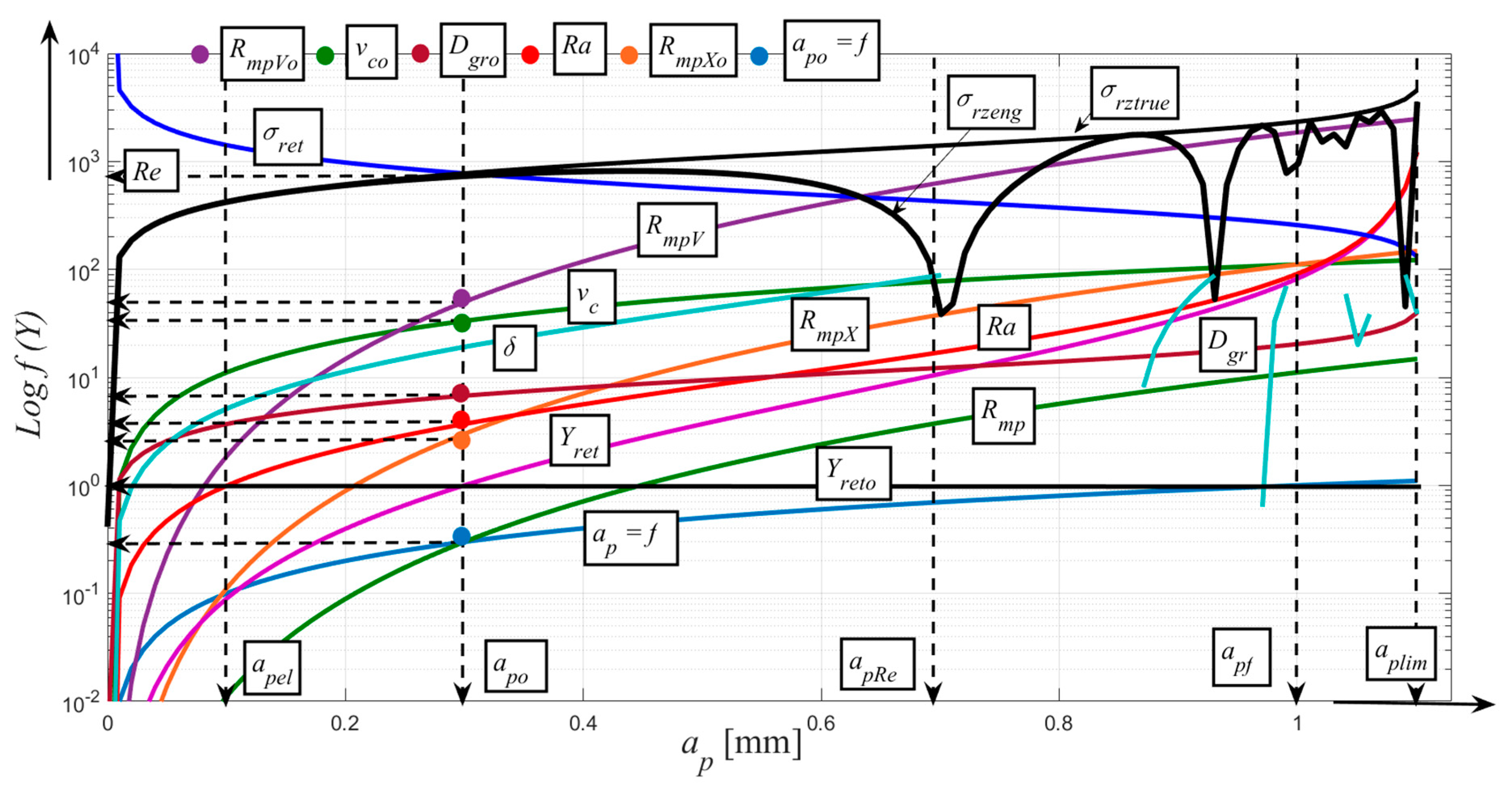
4.1. New Analytical Work and Results

New analytical solutions have required requirements based on new experiments:
  • a sufficiently discreetly expressed course of variation of the cutting parameters;
  • a sufficiently discreetly expressed variance of Ra and other surface topographical parameters;
  • a sufficiently discreetly expressed surface texture and texture after machining;
  • a sufficiently discreetly expressed grain size of the coating;
  • a sufficiently discretely expressed adhesion of the coating material on the substrate according to the choice of particular cutting parameters;
  • optimizing the choice of particular cutting parameters according to the technology and utilization requirements;
  • discrete expression of the most important technological functions.

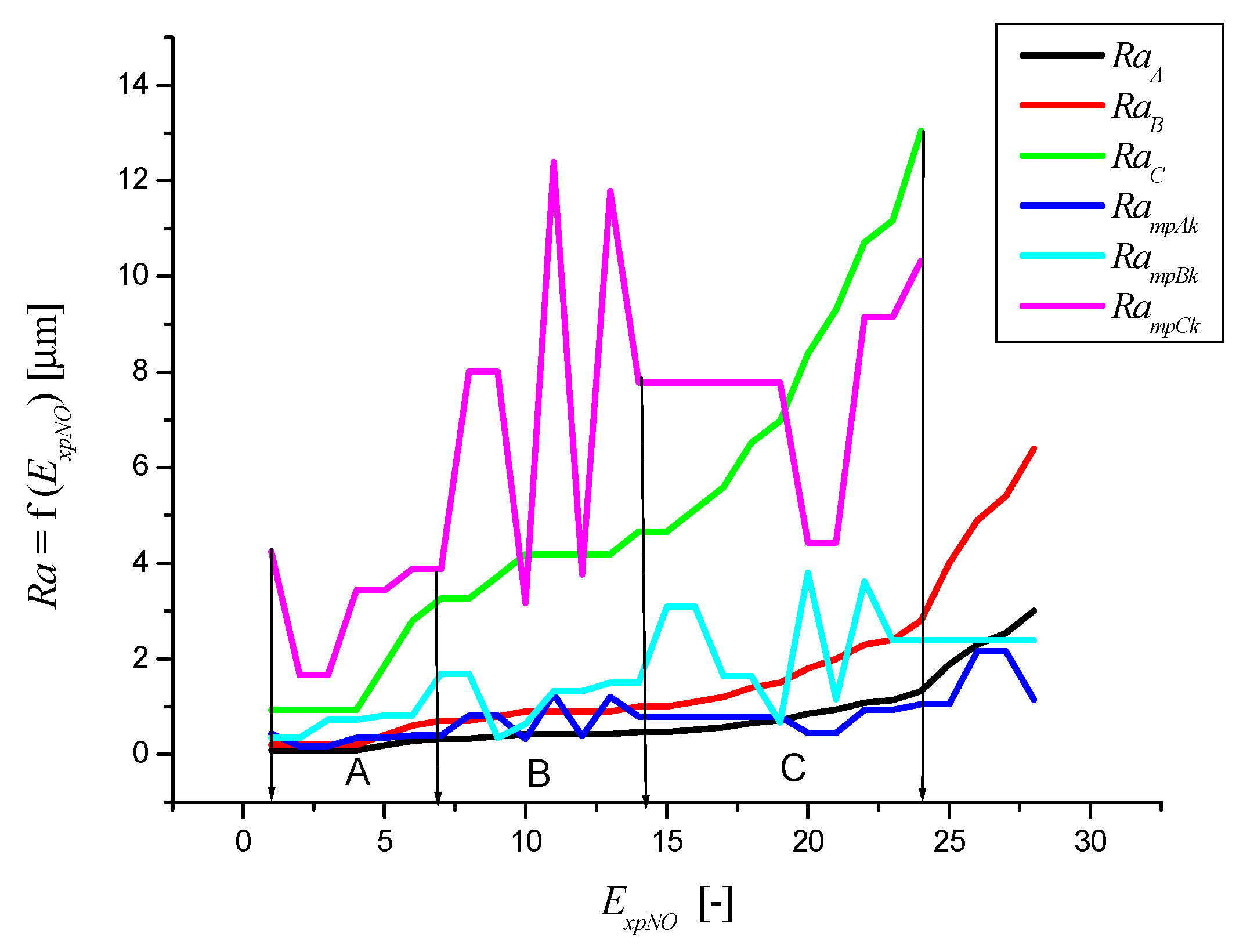
The Ratio of Machining Parameters Rmp

The function Ratio of Machining Parameters Rmp [-] has been newly derived to fulfil these requirements. In the form of continuous/regression, it is a regression of the variance of the cutting parameters according to the number of experiment Rmp = f (ExpNO) [-], where the ExpNO is the experiment number.
In this case, an inadequately discrete curve between the working parameters (Wp) of the cut and the numbers of individual experiments was obtained Wp = f (ExpNO) [-]. It is graphically similar to the relationship between the measured Ra values according to the number of experiments Ra = f (ExpNO).
In Table 5 and the graphs, the parameters for steel EN S235JRG1 are simply labelled with A, for Stellite 6 with letter B, and Carbide WC-Co with letter C (Figure 7). In Figure 7, the following conclusions are explicitly presented based on the results obtained. The supplier of the base material EN S235JRG1 is the company Schmolz Bickenbach, Ltd. (Hustopeče u Brna, Czech Republic). Stellite 6 and Carbide alloy WC- Co were realized in close cooperation with the company Plasmametal Ltd. (Brno, Czech Republic).
Polynomial regression equations for individual materials are given by (42) to (44):
R m p A   = 3.94879 + 0.29167 E x p N O
R m p B = 5.01964 + 0.37076 E x p N O
R m p C = 9.49936 + 0.70157 E x p N O
In addition to the parameters defined above, the following parameters are represented in the physically discrete equations: f0 [mm]—feed at the neutral plane, vc0 [m⋅min−1]—the speed at the neutral plane; ap0 [mm]—depth of cut at the neutral plane, Ra0 [μm]—surface roughness at the neutral plane, kmes [-]—constant according to the Ra measurement conditions, vibration etc.
The parameters for the neutral plane are determined by the relationships (45) to (48):
v c 0 = ( R a 0 + 4.65991 ) 0.06193
a p 0 = 2 ( 0.405 + 0.005 v p o p t )
D g r 0 = 10 3 R a 0 E m a t
f 0 = D g r 0 8.51
The new parameter YretS in the above relationships is the deviation of the tool track from the set plane. The YretS parameter is also used to calculate the tangential shear stress in the cut σt (49) and also to determine the deviation δ from the set plane:
σ t = 2 10 3 E m a t Y r e t Y r e t 0
where YretS0 is the deviation of the tool track from the set cutting plane at the neutral depth ap0, while it has a constant value YretS0 = 1 mm.
This deviation is given by (50):
δ = a r c t g ( Y r e t h ) 180 π
and at the neutral plane of the cut is given by (51):
δ 0 = a r c t g ( Y r e t 0 a p 0 ) 180 π
The present equation Ramp = f (Rmp, ExpNO) is sufficient to satisfy this requirement. If we know the integral quantity of roughness, we can derive other main topographical functions according to the previously derived equations of equilibrium [21,22,23,24,25,26] and we can calculate with them further. Further, the Yret value preferably serves to calculate the tangential forces and the stress for the adhesion control. The structure and texture of the surface after machining is sufficiently discretely expressed by equations (Ra, Yret, ap) = f (Rmp, ExpNO). For sufficiently discreetly expressed grain size Dgr of the coating material was derived [21,22,23,24,25,26] the equation of Equation (35) for different materials. Discrete distribution of particle size distribution by discrete cutting parameters can be determined by Dgr = f (Rmp, ExpNO).

4.2. Adhesion Adhmp of the Coating Material on the Substrate

The adhesion of the coating material on the substrate (Table 6), sufficiently discretely expressed by choice of cutting parameters, can be calculated according to the newly derived relation (52):
A d h m p = k a d h 10 5 R a m p D g r E m a t
The constant kadh [-] serves for practical calculations for the roughness compensation Ra from the machined surface to the technologically required level. There are cases in which the roughness Ra needs to be reduced or increased to achieve higher adhesion forces between substrate and coating/spray. Constant kadh also defines precisely how to edit the cutting parameters.
The optimization of the choice of cutting parameters for the most suitable roughness of the substrate according to the actual grain size of the coating/spraying can be done by using Table 1 to select the most appropriate combination of cutting parameters according to the adhesion and technological application condition requirements for the selected Section along the (x) axis, where (x) are the discrete values Wp = f (ExpNO). This is a discrete expression of important technological functions. These functions are in the basic concept of the requirement set on: Rmp, Rmptr, Ra substrate, Dgr coating, normal machining true stress σrz, normal machining engineering stress σrzx, residual machining true stress σrez (19), residual machining engineering stress σrezx (20), equivalent depth hekv = f (ap). In Table 6, based on relationship (52), the adhesion values are determined for each experiment performed.
A more detailed analysis can then be carried out by adding the functions mentioned above to other functions, namely the discretely determined adhesive tension Adhmp and cutting force Fc, the kadh proportionality constant and other selected functions according to the implicit relationship (Adhmp, Fc, kadh, ...) = f (Rmp, ExpNO). The calculation applies to materials in general and can, therefore, be implemented separately for each type of substrate, coating/spraying. The graphs for the studied steel EN S235JRG1/Stellite, Stellite/Stellite and Stellite/Carbide WC-Co here are located under Table 6 and in Figure 7 and Figure 8. In Table 7 and Table 8 parameters for the experiment numbers ExpNO = 1–28 are selected, measured, and calculated.
Figure 8 shows the data obtained for adhesion, for a combination of EN S235JRG1 (A) and Stellite 6 (B), Carbide WC-Co. Based on the analysis, it is again assumed that Section B is the most suitable in relation to Section A and C in terms of adhesion to the base material.
In Figure 9, Figure 10 and Figure 11, Sections A, B, C are classified similarly as in Figure 7, and the individual sections are explicitly classified.

5. Comparison and Verification

To verify the actual procedure, we selected the results published in [7] and [10]. The reason for this selection is similar to the concept and objectives pursued by the experiments. Consistency in the roughness parameters is essential because, in our concept, it is a fundamental value for the other parameters in the cut. It guarantees conformity also in other monitored parameters where we have exactly defined functional relations. We compare the results as very good. We proved them in numerical values according to Table 9 and Table 10 and graphically, according to Figure 12 and Figure 13.

5.1. Comparison and Verification for Stellite

In [10], the authors selected a total of 27 experiments (ExpNO = 1–27) and the following combinations and ranges of cutting parameters: vc = 30–80 (m⋅min−1), feed f = 0.2–0.3–0.5–0.7–0.8 (mm) and depth of cut ap = 0.15–0.23–0.31 (mm). The results that are essential for comparison and verification are shown (Figure 12 and Figure 13). Desirability function analysis is applied to predict the optimal cutting conditions when turning Stellite 6 cobalt alloy. The optimal cutting parameters to achieve a minimum value of Ra are r = 0.605 mm, vc = 80 m⋅min−1, f = 0.16 mm⋅rev1, and ap = 0.45 mm. For maximum MRR, the optimal cutting conditions are r = 0.674 mm, vc = 80 m⋅min−1, f = 0.083 mm⋅rev1, ap = 0.45 mm. Simultaneous compromise between productivity and quality can be obtained by the following optimal cutting conditions: r = 0.858 mm, vc = 80 m⋅min1, f = 0.160 mm⋅rev1 and ap = 0.45 mm. The optimization was conducted according to three approaches, which are “quality optimization”, “productivity optimization” and “quality-productivity combination”.

5.2. Comparison and Verification for Carbide alloy WC-Co

For comparison we chose also a work published by [7] because of the lack of published data on this topic. They studied the effect of various combinations of these parameters on the machining performance such as surface roughness, cutting force, cutting power and material removal rate. We achieved a good agreement by verifying the surface roughness Ra and RaMES of the machined surface. The results are numerically presented in Table 9 and graphically in Figure 12. Again, a good comparative agreement can be stated.
The presented graphs and tables in Subchapters 5.1 and 5.2 show satisfactory comparative conformity, namely in Table 8 and Figure 11, it is the closeness of conformity R2 = 0.97 and in Table 9 and Figure 12, the tightness of conformity R2 = 0.89. We can, therefore, say that the effect of correlation between the parameters measured and those we derived, the number of experiments on the materials in question is adequate for subsequent applications and predictions when setting technological parameters for subsequent implementation and verification in the application sphere.

5.3. The results Achieved

The results achieved within the solution of the presented paper can be summarized as follows:
(a)
Derivation of main functions for the solution (Section 4.1);
(b)
Diagrams of deformation for studied materials and results (Section 4);
(c)
The conception of a solution and main requirements (Section 5);
(d)
The conception of experiments (Section 3);
(e)
Main numerical and graphical results of experiments (Section 4);
(f)
Comparison and verification results (Section 5);
(g)
Discrete calculation method based on newly derived parameter Rmp (Section 3.4);
(h)
Calculation of the most important stress-strain parameters in the cut according to the newly derived equation of equilibrium (Section 3.4).
It is necessary to remind readers that the roughness of the machined surface Ra is one of the most important variables in the presented concept of analytically described machining processes. This is because it is functionally related to all other process functions of machining processes. The roughness parameter Ra is closely related to the other parameters of the structure and texture of the machined surfaces and, in the context of integrity, to its functionality and durability, in particular, it is necessary for calculating values and distribution functions in the machining process mechanism. In particular, these are the instantaneous and space-time, that is, the continuous stress and deformation functions. These relate not only to the instantaneous state and changes in the physical-mechanical parameters of the material being machined but also to the condition and changes of the machine tool and the entire technology. The way of dealing with these items is described in detail and is available in granted patents and publications [21,22,23,24,25,26].

6. Conclusion and Future Works

The submitted work confirms the measured, predicted and verified results presented in individual sections:
  • Based on the concept of experiments (Section 3), the most important stress-strain parameters in the Section were evaluated according to the newly derived equilibrium equation; the Rmp parameter was also derived by the discrete calculation method (Section 3.4);
  • On the basis of the documented results, the newly proposed solutions can be considered as verified, i.e., ready for applications in theory and practice (Section 4), especially the deformation diagrams of studied materials and results and the main numerical and graphical results of experiments.
The main functions necessary for solving the problem (Section 4.1) are presented in the following equations:
  • In particular, the newly derived equilibrium equation for the determination of the most important stress-strain parameters on the cut through rigid tools (2);
  • A new procedure for calculating the cutting force fc (23);
  • The newly derived parameter Rmp (38) to (41);
  • From a technological point of view, the method of expressing discrete relations between the cut parameters, the specific cut parameters as well as the resulting adhesion parameters is very important; the new parameter Rmp provides the ability to accurately calculate the combination of cutting parameters vc, f and ap so that desired results such as surface roughness, cutting force and material removal rate can be achieved with confidence both in theory and practice;
  • Newly derived, also technologically very important and generally valid stress-strain functions, based on knowledge of Rmp (38) to (52);
The presented results are gradually verified and implemented into the production process in cooperation with Plasmametal, Ltd. in Brno; in the future, many other research and experimental works on other materials and coatings are connected with the fact that the research results will be similarly analysed, verified and compared on both theoretical and application basis. Applied research should focus primarily on the design stages of machining preparation to meet the qualitative and related economic requirements, in particular, the specifics of hard metal spraying technology on the cutting tool substrate.

7. Patents

Valíček, J.; Borovička, A.; Hloch, S.; Hlaváček. P. Method for the design of a technology for the abrasive waterjet cutting of materials Kawj. Inventors: Czech Republic Patent CZ 305514 B6. 23 July 2010.
Valíček, J.; Borovička, A.; Hloch, S.; Hlaváček, P. Method for the Design of a Technology for the Abrasive Waterjet Cutting of Materials. U.S. Patent 9073175, 7 July 2015.

Author Contributions

Conceptualization, J.V., M.H. and M.K.; methodology, J.Ř.; validation, M.G., M.D. and M.Š.; formal analysis, A.V.; investigation, J.F. (Jaroslava Fulemová); data curation, J.F. (Jan Filipenský); writing—original draft preparation, J.V.; writing—review and editing, M.H., M.K. and M.G.; visualization, A.V., M.D., M.Š.; supervision, J.F. (Jan Filipenský); project administration, J.F. (Jaroslava Fulemová); funding acquisition, J.Ř. All authors have read and agreed to the published version of the manuscript.

Funding

The present contribution has been prepared under project LO1502 ‘Development of the Regional Technological Institute ‘under the auspices of the National Sustainability Programme I of the Ministry of Education of the Czech Republic aimed to support research, experimental development and innovation and the project APVV 15-0405 ‘Complex use of X-ray diffractometry for identification and quantification of functional properties of dynamically loaded structural elements from important technical materials‘.

Conflicts of Interest

The authors declare no conflict of interest.

References

  1. Zaman, H.A.; Sharif, S.; Kim, D.; Idris, M.H.; Suhaimi, M.A.; Tumurkhuyag, Z. Machinability of Cobalt-based and Cobalt Chromium Molybdenum Alloys-A Review. Procedia Manuf. 2017, 11, 563–570. [Google Scholar] [CrossRef]
  2. Davis, J.R. Nickel, Cobalt, and Their Alloys; ASM International: Materials Park, OH, USA, 2000. [Google Scholar]
  3. Riddihough, M. Stellite as a wear-resistant material. Tribology 1970, 3, 211–215. [Google Scholar] [CrossRef]
  4. Ozturk, S. Machinability of stellite-6 coatings with ceramic inserts and tungsten carbide tools. Arab. J. Sci. Eng. 2014, 39, 7375–7383. [Google Scholar] [CrossRef]
  5. Kapoor, S. High-Temperature Hardness and Wear Resistance of Stellite Alloys. Master’s Thesis, Carleton University Ottawa, Ottawa, ON, Canada, 2012. [Google Scholar]
  6. Hasan, S.; Mazid, A.M.; Clegg, R.E. The basics of stellites in machining perspective. Int. J. Eng. Mater. Manuf. 2016, 1, 35–50. [Google Scholar] [CrossRef]
  7. Shao, H.; Li, L.; Liu, L.J.; Zhang, S.Z. Study on machinability of a stellite alloy with uncoated and coated carbide tools in turning. J. Manuf. Process. 2013, 15, 673–681. [Google Scholar] [CrossRef]
  8. Chavoshi, S.Z. Modelling of surface roughness in CNC face milling of alloy stellite 6. Int. J. Comput. Mater. Sci. Surf. Eng. 2013, 5, 304–321. [Google Scholar] [CrossRef]
  9. Hasan, M.S.; Abdul, M.M.; Clegg, R.E. Optimisation of the machining of stellite 6 PTA hardfacing using surface roughness. Key Eng. Mater. 2010, 443, 227–231. [Google Scholar] [CrossRef]
  10. Saidi, R.; Fathallah, B.B.; Mabrouki, T.; Belhadi, S.; Yallese, M.A. Modeling and optimization of the turning parameters of cobalt alloy (Stellite 6) based on RSM and desirability function. Int. J. Adv. Manuf. Technol. 2019, 100, 2945–2968. [Google Scholar] [CrossRef]
  11. Xiong, J.; Nie, F.; Zhao, H.; Zheng, L.; Luo, J.; Yang, L.; Wen, Z. Microstructure Evolution and Failure Behavior of Stellite 6 Coating on Steel after Long-Time Service. Coatings 2019, 9, 532. [Google Scholar] [CrossRef] [Green Version]
  12. Li, Z.; Cui, Y.; Wang, J.; Liu, C.; Wang, J.; Xu, T.; Lu, T.; Zhang, H.; Lu, J.; Ma, S.; et al. Characterization of Microstructure and Mechanical Properties of Stellite 6 Part Fabricated by Wire Arc Additive Manufacturing. Metals 2019, 9, 474. [Google Scholar] [CrossRef] [Green Version]
  13. Shahroozi, A.; Afsari, A.; Khakan, B. Microstructure and mechanical properties investigation of stellite 6 and Stellite 6/TiC coating on ASTM A105 steel produced by TIG welding process. Surf. Coat. Technol. 2018, 350, 648–658. [Google Scholar] [CrossRef]
  14. Baiamonte, L.; Tului, M.; Bartuli, C.; Marini, D.; Marino, A.; Menchetti, F.; Pileggi, R.; Pulci, G.; Marra, F. Tribological and high-temperature mechanical characterization of cold sprayed and PTA-deposited Stellite coatings. Surf. Coat. Technol. 2019, 371, 322–332. [Google Scholar] [CrossRef]
  15. Azizpour, M.J.; Tolouei-Rad, M. Evaluation of residual stress in HVOF stellite-6 coatings using non-contact drilling. Mater. Res. Express 2019, 6, 066577. [Google Scholar] [CrossRef]
  16. Zhou, T.; He, L.; Wu, J.; Du, F.; Zou, Z. Prediction of Surface Roughness of 304 Stainless Steel and Multi-Objective Optimization of Cutting Parameters Based on GA-GBRT. Appl. Sci. 2019, 9, 3684. [Google Scholar] [CrossRef] [Green Version]
  17. Shoja-Razavi, R. Laser surface treatment of stellite 6 coating deposited by HVOF on 316L alloy. J. Mater. Eng. Perform. 2016, 25, 2583–2595. [Google Scholar] [CrossRef]
  18. Kong, G.; Zhang, D.; Brown, P.D.; McCartney, D.G.; Harris, S.J. Microstructural characterisation of high velocity oxyfuel thermally sprayed Stellite 6. Mater. Sci. Technol. 2003, 19, 1003–1011. [Google Scholar] [CrossRef]
  19. Magarò, P.; Marino, A.L.; Di Schino, A.; Furgiuele, F.; Maletta, C.; Pileggi, R.; Sgambitterraa, E.; Tului, M. Effect of process parameters on the properties of Stellite-6 coatings deposited by Cold Gas Dynamic Spray. Surf. Coat. Technol. 2019, 377, 124934. [Google Scholar] [CrossRef]
  20. Traxel, K.D.; Bandyopadhyay, A. First Demonstration of Additive Manufacturing of Cutting Tools using Directed Energy Deposition System: Stellite™-Based Cutting Tools. Addit. Manuf. 2019, 25, 460–468. [Google Scholar] [CrossRef]
  21. Valíček, J.; Řehoř, J.; Harničárová, M.; Gombár, M.; Kušnerová, M.; Fulemová, J.; Vagaská, A. Investigation of Surface Roughness and Predictive Modelling of Machining Stellite 6. Materials 2019, 12, 2551. [Google Scholar] [CrossRef] [Green Version]
  22. Valíček, J.; Czán, A.; Harničárová, M.; Šajgalík, M.; Kušnerová, M.; Czánová, T.; Kopal, I.; Gombár, M.; Kmec, J.; Šafář, M. A new way of identifying, predicting and regulating residual stress after chip-forming machining. Int. J. Mech. Sci. 2019, 155, 343–359. [Google Scholar] [CrossRef]
  23. Valíček, J.; Harničárová, M.; Öchsner, A.; Hutyrová, Z.; Kušnerová, M.; Tozan, H.; Michenka, V.; Šepelák, V.; Mitaľ, D.; Zajac, J. Quantifying the Mechanical Properties of Materials and the Process of Elastic-Plastic Deformation under External Stress on Material. Materials 2015, 8, 7401–7422. [Google Scholar] [CrossRef] [PubMed] [Green Version]
  24. Valíček, J.; Borovička, A.; Hloch, S.; Hlaváček, P. Method for the Design of a Technology for the Abrasive Waterjet Cutting of Materials. U.S. Patent 9073175, 7 July 2015. [Google Scholar]
  25. Hloch, S.; Valíček, J. Prediction of distribution relationship of titanium surface topography created by abrasive waterjet. Int. J. Surf. Sci. Eng. 2001, 5, 152–168. [Google Scholar] [CrossRef]
  26. Valíček, J.; Borovička, A.; Hloch, S.; Hlaváček, P. Method for the Design of a Technology for the Abrasive Waterjet Cutting of Materials Kawj. Czech Republic Patent CZ 305514 B6, 23 July 2010. [Google Scholar]
  27. Houdková, Š.; Pala, Z.; Smazalová, E.; Vostřák, M.; Česánek, Z. Microstructure and sliding wear properties of HVOF sprayed, laser remelted and laser clad Stellite 6 coatings. Surf. Coat. Technol. 2017, 318, 129–141. [Google Scholar] [CrossRef]
Figure 1. The physical nature is analogous to the beam curvature parameters. (a) in relation to fixed blade machining (b).
Applsci 10 02524 g001
Figure 2. Relation σrz–σrez for EN S235JRG1 material.
Applsci 10 02524 g002
Figure 3. The relation Rmp for EN S235JRG1 material, where apel is the depth of cut at the elasticity limit, ap0 is the depth of cut at the neutral plane, apRe is the depth of cut at the elastic limit, apf is the depth of cut at the failure limit, and aplim is the limit depth of cut.
Applsci 10 02524 g003
Figure 4. Relation Rmp for Stellite material.
Applsci 10 02524 g004
Figure 5. Machining of Stellite 6.
Applsci 10 02524 g005
Figure 6. Measurement of surface roughness.
Applsci 10 02524 g006
Figure 7. Surface roughness after machining, measured and discrete (analytical) roughness. Section A (ExpNO 1–7) insufficient roughness for the desired adhesion, Section B (ExpNO 7–14) very good roughness for the desired adhesion, Section C (ExpNO 14–24) sufficient roughness for the desired adhesion.
Applsci 10 02524 g007
Figure 8. Adhesion Adhmp = f (Ra, Dgr) for the combination A/B and A/C, where: Section A (ExpNO 1–12) insufficient roughness for the desired adhesion, Section B (ExpNO 6–21) very good roughness for the desired adhesion, Section C (ExpNO 21–28) sufficient roughness for the desired adhesion.
Applsci 10 02524 g008
Figure 9. Comparison of working parameters LOG f (Wp) = f (ExpNO) for EN S235JRG1, where: Section A (ExpNO 1–6) insufficient roughness for the desired adhesion, Section B (ExpNO 6–13) very good roughness for the desired adhesion, Section C (ExpNO 13–24) sufficient roughness for the desired adhesion.
Applsci 10 02524 g009
Figure 10. Comparison of working parameters LOG f (Wp) = f (ExpNO) for Stellite 6, where: Section A (ExpNO 1–6) insufficient roughness for the desired adhesion, Section B (ExpNO 6–21) very good roughness for the desired adhesion, Section C (ExpNO 21–24) sufficient roughness for the desired adhesion.
Applsci 10 02524 g010
Figure 11. Comparison of working parameters LOG f (Wp) = f (ExpNO) for Carbide WC-Co, where: Section A (ExpNO 1–6) insufficient roughness for the desired adhesion, Section B (ExpNO 7–13) very good roughness for the desired adhesion, Section C (ExpNO 13–24) sufficient roughness for the desired adhesion.
Applsci 10 02524 g011
Figure 12. Comparison of parameters Ra, RaMES = f (ExpNO), ExpNo = 1–27 (closeness of conformity R2=0.97).
Applsci 10 02524 g012
Figure 13. Comparison of parameters Ra, RaMES = f (ExpNO), ExpNo = 1–17 (closeness of conformity R2 = 0.89.
Applsci 10 02524 g013
Table 1. Chemical composition values of Stellite 6 determined by EDX measurement and verified as identical to nominal composition (mass %).
CoCrWMoSiMnNiFeC
% Wt59.6828.344.11.691.230.271.660.792.24
Table 2. Nominal values of the stress of the Stellite 6 spray at room temperature.
Rm1Rp0.21Emat1ε1
Stellite 61265 MPa750 MPa237 GPa4 %
1Emat—Young’s modulus of elasticity, Rp0.2—yield strength, Rm—material strength, ε—relative elongation.
Table 3. The nominal value of hardness of Stellite 6 spray in hot condition.
20 °C100 °C200 °C300 °C400 °C500 °C600 °C700 °C800 °C900 °C
HV41039035634533430123515513895
Table 4. Spray parameters.
ParameterValue
Oxygen996 L⋅min−1
Fuel277 L⋅h−1
Barrel length150 mm
Spray distance360 mm
Traverse speed250 mm⋅s−1
Feed rate46 g⋅min−1
Carrier gasNitrogen, 6.5 L⋅min−1
Offset6
Number of passes7
Table 5. Discrete cutting parameters according to individual ExpNO numbers.
ExpNOvc
[m⋅min−1]
f
[mm]
ap
[mm]
λ
[°]
1300.30.1548
2300.30.1572
3300.30.3148
4300.30.3172
5300.70.1548
6300.70.1572
7300.70.3148
8300.70.3172
9300.30.1548
10550.30.1572
11550.30.3148
12550.30.3172
13550.70.1548
14550.70.1572
15550.70.3148
16550.70.3172
17550.50.2360
18550.50.2360
19550.20.2360
20800.80.2360
21800.50.1160
22800.50.3560
23800.50.2342
24800.50.2378
25800.50.2360
26800.50.2360
27800.50.2360
28800.50.2360
Table 6. Selected, measured and calculated parameters for the number of experiments ExpNO = 1–28.
ExpNoRmpA
[-]
RmpB
[-]
RmpC
[-]
RaA
[µm]
RaB
[μm]
RaC
[µm]
Adhmp A/B
[MPa]
Adhmp A/C
[MPa]
14.245.3910.200.090.20.935111230
24.535.7610.900.090.20.935111230
34.826.1311.600.090.20.934261026
45.126.5012.310.090.20.934261026
55.416.8713.010.190.41.869642322
65.707.2413.710.280.62.799642322
75.997.6214.410.330.73.268041937
86.287.9915.110.330.73.268041937
96.578.3615.810.380.83.7210662567
106.878.7316.520.420.94.1910662567
117.169.1017.220.420.94.198892147
127.459.4717.920.420.94.198892147
137.749.8418.620.420.94.1920134846
148.0310.2119.320.471.04.6620134846
158.3210.5820.020.471.04.6616794041
168.6210.9520.720.521.15.1216794041
178.9111.3221.430.561.25.594591105
189.2011.6922.130.661.46.5215613757
199.4912.0622.830.711.56.985341285
209.7812.4423.530.851.88.3815093634
2110.0712.8124.230.942.09.3112763072
2210.3713.1824.931.082.310.79552300
2310.6613.5525.641.132.411.210612555
2410.9513.9226.341.322.813.010612555
2511.2414.2927.041.884.018.610612555
2611.5314.6627.742.304.922.810612555
2711.8215.0328.442.545.425.110612555
2812.1215.4029.143.016.429.810112434
Table 7. Continued Table 6 for σrz, σrzx, σrez (ExpNO = 1, 10, 19, 28).
ExpNoUnit1101928
σrezAMPa0.201.172.8220.27
σrezxAMPa0.201.132.6718.46
σrezBMPa0.160.671.162.17
σrezxBMPa0.180.651.122.07
σrezCMPa1.122.463.383.77
σrezxCMPa1.092.310.413.2
σrzAMPa10.547.178.6335.2
σrzxAMPa10.245.474.4305.3
σrzBMPa32.5146.1243.51039
σrzxBMPa31.4139.2222.0826
σrzCMPa322.61452242010324
σrzxCMPa303104432873
Table 8. Continued Table 6 for Dgr, hekv, σ, Fc (ExpNO = 1, 10, 19, 28).
ExpNoUnit1101928
DgrAµm0.0040.0210.0510.364
DgrBµm0.0090.0570.1791.818
DgrCµm0.0761.65413.82134.187
hekvAmm0.2201.6541.5525.451
hekvBmm0.2170.9151.4454.324
hekvCmm0.2030.7030.9791.782
σAMPa751.921227.861029.341492.50
σBMPa865.081412.661184.261717.10
σCMPa1225.112000.591677.132431.80
Scmm20.0450.0450.0460.100
FcAN33.8455.2547.35191.20
FcBN38.9363.5754.48220.00
FcCN55.1390.0377.15311.50
Table 9. Comparation and Verification [10].
ExpNORaRaMESExpNORaRaMES
(-)(µm)(µm)(-)(µm)(µm)
11.090.98151.501.60
21.060.95160.730.53
31.381.40170.860.68
41.671.90180.790.60
51.611.78191.311.30
61.391.42201.191.12
72.042.65211.171.10
81.782.10220.730.53
91.872.28230.590.36
101.171.10240.680.46
111.281.25251.030.91
121.231.18260.820.64
131.561.70270.890.72
141.641.83Median1.231.23
Table 10. Comparison and Verification [7].
ExpNORaRaMESExpNORaRa
(-)(µm)(µm)(-)(µm)(µm)
11.991.56102.702.86
22.512.48112.161.83
32.843.17122.241.97
41.781.24132.041.63
52.492.43142.793.07
62.221.93151.811.29
71.951.49162.532.52
82.422.30171.520.91
91.580.98Median2.211.98

