Abstract
In this study, the strengthening effects of different lamination conditions on carbon fiber reinforced polymers (CFRPs) for thin-walled storage tanks (TSTs) subjected to internal pressure under dynamic loads were experimentally investigated. A total of three small-scale models of TSTs were used for the investigation, including non-strengthened specimens, specimens strengthened with 0° CFRP layers, and specimens strengthened with 0°/90° CFRP layers. There were two types of tests for every specimen: the static and dynamic tests. A new experimental method using small steel balls was applied to create internal pressure in the TSTs. The results show that small steel balls could be used to increase the internal pressure compared to a normal liquid. Furthermore, the similarity rules for small-scale TSTs with small steel balls inside were also studied to consider the applicability of the models. The experimental results indicated that the CFRP layer could effectively restrain both static and dynamic hoop strains in the TSTs. Moreover, the CFRP layer could also remarkably reduce the impact of sloshing on the TST shells. The 0° CFRP layer proved to have better effects than the 0°/90° CFRP layers on the strengthening of the TSTs against dynamic loads.
1. Introduction
Thin-walled storage tanks have been widely used in many fields as fluid tanks for chemical, electrical power, and food engineering, among others. TSTs are also often used as key facilities in whole production systems. The destruction of TSTs will cause an interruption in the production process, and can even lead to disasters. However, a large number of TSTs have appeared with increasing signs of deterioration, reducing the load-carrying capacity, because of corrosion or aging degradations. Moreover, large earthquakes, which have occurred frequently in recent years, especially in the Pacific Ocean, can cause damage to not only degraded tanks, but also to existing healthy tanks [1,2]. Therefore, strengthening these structures to improve the performance against the buckling caused by dynamic events is necessary to ensure the sustainable development of economy and health infrastructures.
Several failure modes were observed in TSTs due to past earthquakes [3], such as anchorage failure, tank support failure, roof failure, foundation failure, connecting piping damage, and shell buckling. In all of these types of damage, because of the thinness of the TSTs, shell walls are susceptible to the elasto-plastic buckling and elastic buckling under various types of loads, especially dynamic loading. The buckling behaviors of TST shell walls have been investigated by several researchers [4,5,6,7,8,9,10,11]. The buckling failure modes can include shear buckling and bending buckling [5]. Some cases of bending buckling can be elephant foot buckling (EFB) or diamond buckling. The EFB, which is defined as the outward bulge around the base of the tanks, is related to the elasto-plastic buckling of TSTs. Furthermore, the elastic bucking of TSTs includes the shear buckling of shells or diamond buckling at the bottom of the TSTs [10,11]. Our main interest in this study was to strengthen the effects of shell walls in TSTs against dynamic loading in the elastic areas.
The typical and traditional solution to strengthening aging TSTs is to weld with bulky and heavy steel plates, which are difficult to repair and are prone to corrosion. In addition, the reparation process can interrupt the business and can cause damage to storage materials during the structural renovations. Recently, the use of carbon fiber reinforced polymers (CFRPs) to strengthen concrete beams and columns has been popular because CFRPs have many advanced characteristics, such as having high strength and corrosion resistance, and being lightweight [12,13,14,15]. Moreover, the use of CFRPs to improve the load-carrying capacity and performances of steel structures has also attracted many researchers [16,17,18,19,20,21,22]. As a result, CFRP strengthening is an effective way to not only improve the performances of structures, but also to maintain the working conditions of TSTs. While the strengthening effects of CFRP in steel structures were proved by many researchers, a limited amount of research has been reported on the strengthening effects of CFRP for TSTs, especially TSTs subjected to dynamic loads.
Regarding studies about the strengthening effects of CFRP layers for thin-walled steel plates, Al-Azzawi et al. [23,24] conducted a serious of experiments and numerical methods to investigate the shear capacity and fatigue resistance of thin-walled plate girder web panels strengthened by novel preformed-corrugated FRP panels under static and cyclic loading. They found that the ultimate load capacity was increased by 29% for GFRP strengthening and 20% for CFRP strengthening with three layers of CFRP and GFRP. Khazaei Poula et al. [25] carried out a series of laboratory tests to evaluate the effect of the number of CFRP layers and the fiber orientations on a thin steel plate shear wall under a cyclic shear load. The results showed that applying CFRP laminates can significantly increase the yield strength, ultimate strength, and secant stiffness. In addition, the highest shear strength and stiffness can be obtained by using the principal orientation of CFRP laminates along the direction of the tension fields. Bambach et al. [26] investigated the strengthening effects of externally bonded CFRP on axially compressed square hollow sections (SHSs) of cold-formed G450 steel. They concluded that the application of CFRP to slender sections delays local buckling and subsequently results in significant increases in elastic buckling stress, axial capacity, and the strength-to-weight ratio of the compression members.
The strengthening effects of CFRP for thin metallic cylindrical shells were investigated by other researchers. Batikha et al. [27,28] numerically analyzed the impact of the buckling capacity of thin metallic shells using CFRP sheets under two loading conditions: uniform internal pressure accompanied by an axial load and axial loads with geometric imperfections. They found that thin metal cylindrical shell structures are susceptible to an elasto-plastic instability failure at the base boundary, known as EFB, and presented a method to strengthen cylindrical shells against EFB, with a small amount of FRP used at a critical location. The results showed that FRP could eliminate the EFB and could increase the buckling strength. Vakili and Showkati [29] also used finite element analysis to investigate the strengthening effects of FRP for steel thin-walled cylindrical shells against EFB under the simultaneous loading of axial compression and high internal pressure. They also surveyed the effect of the FRP location on the capacity of strengthened tanks. The results indicated that locating FRP in the area of the EFB occurrence, which is positioned near the base, can lead to the best strengthening result. Bhetwal and Yamada [30] presented a novel method of strengthening thin-walled steel cylindrical shells against buckling during axial compression by coating CFRPs on both sides. They discussed the effects of reinforcement and the angle of fiber orientation on the buckling strength and buckling modes of thin-walled shells using three kinds of analytical procedures: the conventional linear eigenvalue buckling analysis, the reduced stiffness buckling analysis, and the fully nonlinear numerical experiments. They concluded that the buckling load-carrying capacity of thin cylindrical shells increases with CFRP reinforcement when analyzed with linear and RS analyses. The load-carrying capacity before buckling of thin cylindrical shells increased, depending on the thickness of the CFRP reinforcement, by up to 70% with a 2 mm thickness and 100% with a 4 mm thickness. This increasing amount varied according to the angle of the fiber orientation. Matsumoto et al. [31] experimentally investigated the strengthening effects of circumferential CFRP for steel cylinders under axial compression. The results showed that circumferential CFRP strengthening significantly improved the carrying capacity and ductility capacity regarding axisymmetric plastic buckling. Nhut and Matsumoto [32] numerically studied the strengthening effects of CFRP in various types of steel cylindrical storage tanks subjected to internal pressure under a bending shear load. They concluded that CFRP strengthening can increase the ultimate strength of steel storage tanks and the increasing levels depend on the ratio of the tank’s radius to the tank’s thickness, and the ratio of the height of the tanks to the tank’s radius. If the first ratios were lower and the second ratios were higher, the strengthening by the CFRP layer was remarkably effective.
A general conclusion from the literature is that there are almost no studies concerning the strengthening effects of CFRP for TSTs subjected to internal pressure under dynamic loads. Experiments with full-scale TSTs under dynamic loads are impossible because of the complication and limitation of the capacity of the shaking table machine. Moreover, the application of a normal liquid to create internal pressures with the same amplitudes as full-scale TSTs in the experimental models is either impossible or very difficult. The solution for small-scale TSTs, regarding the behavior investigations of liquid-containing tanks under seismic loads, was provided by Maekawa [5]. However, a limitation of this process is that the internal pressure created by the liquid inside the tanks was small because of the dimensions of the small-scale TSTs. Because the volume of a normal liquid in full-scale TSTs is very large, the real values of internal pressures in real TSTs are significantly higher than these values in small-scale models. The small values of the internal pressure can cause difficulty for the investigations of the strengthening effects of CFRP layers on the performance of TSTs under dynamic loads because the impacts of internal pressure on the shells are trivial. In this study, the strengthening effects of CFRP for TSTs under dynamic loads were investigated via experiments. A new experimental method using small-diameter steel balls to create internal pressure for the TSTs was applied because steel balls with a heavy weight can create a higher internal pressure compared to normal liquid substances. The steel balls used had small and uniform diameters (around 1.2 mm). The properties of steel balls can make them move easily under the impact of a dynamic load, which is the same behavior as a normal liquid. Furthermore, the stress concentration of steel balls on a TST shell is also trivial because of the small and uniform diameter of the steel balls. To develop the applicability of small steel balls toward creating higher internal pressures for small-scale models, the similarity rules for small-scale models containing steel balls were developed in this study. In the next steps, the strengthening effects of two types of externally bonded CFRP sheets, including the circumferential CFRP layer (0°) and two-directional CFRP layers (0° and 90°), on the performance of TSTs subjected to internal pressures under dynamic loads were investigated. Finally, the strengthening effects of CFRP on TSTs impacted by sloshing were considered using two height levels of steel balls.
2. Mechanical Properties of Aluminum, CFRP Layers, and CFRP-Aluminum Lamination
2.1. The Mechanical Properties of Aluminum Plates
In this study, a thin-walled aluminum plate was used to make the TSTs because aluminum plate has a small thickness and lower elastic modulus than steel materials; therefore, the investigations of the strengthening effects of CFRP reinforcement was easier. A rectangular aluminum plate with a thickness of 0.4 mm was used to create the shape of the tanks, as shown in Figure 1. The overlap length was 50 mm and was connected using high strength bolts (M8). The diameter of the cylinder was 558.8 mm and the height was 700 mm.
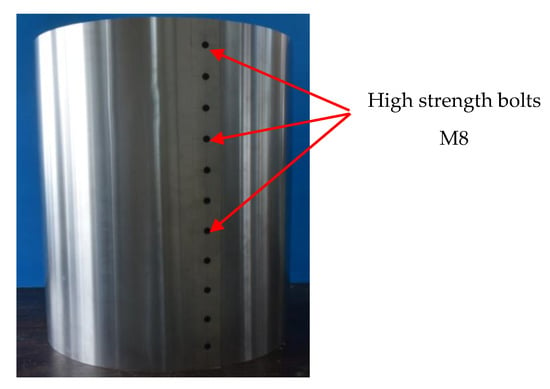
Figure 1.
Circle formation for a thin-walled storage tank (TST).
Material tests, with a total of ten specimens (five specimens in each direction: circumferential and vertical direction), were conducted to determine the elastic modulus of the aluminum plate in both directions. Figure 2 shows the experimental setup and load–strain relations obtained from the material tests for all specimens. The test specimens had the dimension 25 × 250 mm, with a thickness of 0.4 mm. Two strain gauges were stuck on both sides of every specimen to measure the strain values. In Figure 2, the X-direction refers to the circumferential direction, while the Y-direction indicates the vertical direction.
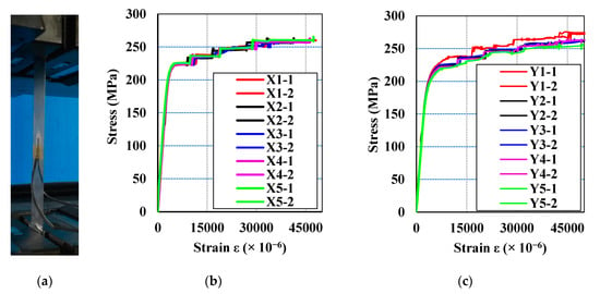
Figure 2.
Experimental setup for material tests (a) and the stress–strain relations of specimens in the circumferential (X) direction (b) and vertical (Y) direction (c).
Table 1 and Table 2 show the calculated elastic moduli of the aluminum plates in both directions. The elastic modulus was determined in the range from 0.2 to 0.5 of the maximum loading values. The elastic modulus was similar in both the circumferential and vertical directions (around 70 GPa).

Table 1.
The calculated elastic moduli of the aluminum plates in the circumferential direction.

Table 2.
The calculated elastic modulus of the aluminum plates in the vertical direction.
2.2. Mechanical Properties of CFRP Layers
Two kinds of commercially available, high-strength cloth carbon fiber sheets were used to investigate the strengthening effects of TSTs under dynamic loads, namely UT70-20 and BT70-20, as shown in Figure 3. UT70-20 is a one-directional carbon fiber sheet (0° fiber orientation angle) and is used to strengthen the circumferential direction of TSTs; whereas, BT70-20 is a two-directional carbon fiber sheet (0°/90° fiber orientation angle) and is used to strengthen the circumferential and vertical directions of TSTs. The carbon fiber was produced in Tokyo, Japan, by Toray Industries, Inc. [33]. Shaped like a sheet, this material is easy to handle and impregnate with resin. The properties of this material were obtained from the manufacturer and are shown in Table 3. The epoxy resin, namely E810LS (product of Konishi, Osaka, Japan), was adopted to form the CFRP laminates that covered the TSTs. The carbon fiber sheets were bonded with the shells of TSTs using E810LS epoxy via the vacuum-assisted resin transfer molding (VaRTM) method [34]. The elastic modulus and Poisson’s ratio of E810LS epoxy are 3 (GPa) and 0.37, respectively, according to the manufacturer’s measurements.
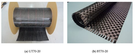
Figure 3.
Carbon fiber sheets.

Table 3.
Characteristics of the carbon fiber sheets.
The carbon fiber sheets were combined by impregnating epoxy to create CFRP layers that covered the outside of the TSTs. The material properties of the CFRP layers were calculated according to the rules of laminae and laminates for composite materials [35], as shown in Equations (1)–(5):
where Ef and Em are the elastic moduli of the carbon fiber and epoxy, respectively; vxy is the major Poisson ratio; υf and υm are the volume fractions of the fiber and epoxy, respectively; and vf and vm are the Poisson ratios of the carbon fiber and epoxy, respectively. In addition, Ex and Ey denote the elastic modulus of the CFRP laminae in the circumferential and vertical directions, respectively, after covering the TSTs, and Gxy represents the shear modulus of the CFRP laminate. Table 4 shows the properties of 0°/90° and 0° CFRP layers, which are denoted by 0°/90° and 0°, respectively. In the table, tf and tm are the thicknesses of the fiber and epoxy, respectively, and tc is the total thickness of the CFRP layers.

Table 4.
The properties of 0°/90° and 0° orientations of the carbon fiber reinforced polymer (CFRP) layers.
2.3. Mechanical Properties of the CFRP-Aluminum Composite Plates
The mechanical properties of the CFRP-reinforced aluminum lamination were calculated based on the macro-mechanical components of laminates assuming that the CFRP layers and aluminum were perfectly bonded through the use of adhesives [35]. Furthermore, if a plate is thin and there are no out-of-plane loads, it can be considered to be under plane stress. Therefore, the properties of CFRP-reinforced aluminum lamination could be calculated according to plane stress conditions. The plane stress condition for CFRP-reinforced aluminum lamination is shown in Figure 4. Consider a laminate made of n plies, as shown in Figure 4. Each ply has a thickness of tk and the thickness of the laminate is h. The in-plane properties of the CFRP-reinforced steel lamination can be determined using Equations (6)–(12). Table 5 shows the resulting calculated mechanical properties of the CFRP-aluminum lamination. In the table, UT0 denotes the aluminum section strengthened using a 0° CFRP layer, whereas BT0/90 represents the aluminum section strengthened using a 0°/90° CFRP layer.
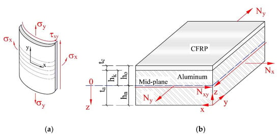
Figure 4.
Plane stress conditions for a thin plate (a) and a CFRP-reinforced aluminum lamination (b).

Table 5.
The mechanical properties of the CFRP-aluminum lamination.
In Equations (6)–(12), (σx, σy, σxy) and () are the principal stress and mid-plane strain components associated with the x-y plane, respectively; tc is the thickness of the CFRP layer; ta is the thickness of the aluminum; and denotes the components of the inverse matrix .
3. Experimental Programme
3.1. Test Ring and Specimen Configurations
Figure 5a shows the test ring and specimen configurations. The aluminum plates, with a thickness of 0.4 mm, were bent to form the TSTs and were held together using 11 high-strength M8 bolts, which have small bolt head thicknesses (see Figure 1). The created TSTs had an outside diameter of 559.6 mm and were 700 mm in height. These TSTs were fixed by a couple of steel cylinders at the top and bottom of the TSTs. For each specimen, cylinder 1 (inside cylinder) had a 558.8 mm outside diameter, a 25 mm height, and 22 mm thickness. The outside diameter of cylinder 1 was also the inside diameter of the TST. In order to fix the TST, four quarters of cylinder 2 were used to connect to cylinder 1 using M10 screws. Cylinder 2 had a 600 mm outside diameter, a 25 mm height, and a 16 mm thickness. The TST’s shell was kept fixed between cylinders 1 and 2. While the inner diameter of cylinder 1 was a little bit larger than the outside dimension of each TST, the clearance could be eliminated after tightening the M10 screws. Figure 6 shows the connection method of the specimens with the shaking table machine. The connecting process included two steps. First, a 12 mm thick bottom steel plate was connected to the shaking table machine using 13 M12 bolts. Then, the specimen was connected to the bottom steel plate using 12 M10 screws through the available bolt holes in cylinder 2 and the bottom steel plates. Figure 5b shows the positions of the stuck strain gauges to investigate the strain values of the specimens. The strain gauges were stuck in the circumferential direction of the TSTs to measure the hoop strain values of the specimens. Strain gauge numbers 1 to 11 were used to investigate the strain values in the vertical direction, while strain gauges 6 and 12 to 21 were used to survey the variation of the strain values in the horizontal direction.
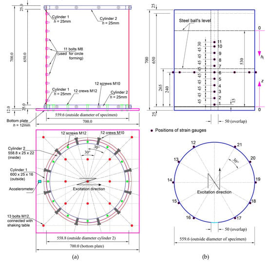
Figure 5.
Test ring and specimen configuration (a) and positions of strain gauges (b).
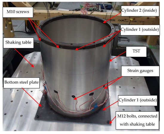
Figure 6.
Test setup: connecting the TST with the shaking table machine.
3.2. Similarity Rules for Small-Scale Models
According to API 650: Welded Steel Tanks for Oil Storage [36], the real diameter of the TST prototype can range from 5 m to more than 20 m, depending on the storage requirement of the materials inside. The ratio of the diameter and thickness (d/t) of the TSTs varied from 600 to 3000. In this study, the scale factor λ was calculated using the ratio of the diameter of the real-world prototype and a small-scale TST (dp/dm), or the ratio of the height level of the storage liquid in the real-world prototype and small-scale TST (hlp/hlm), as shown in Equation (13). The selected small-scale models in the paper had a ratio of d/t around 1400, which is the average value in the API 650 standard. The scale factors of the models were around 1/10 to 1/40, depending on the real-world prototype of the TSTs.
The pressure measured in a small-scale model should be scaled up to the real-scale. Froude scaling is commonly used in the sloshing model test [37,38]. A small-scale model test was conducted based on the assumption that a test using Froude scaling can reproduce sloshing impacts that are representative of the real-world prototype. The similarity rules for small-scale TSTs in this study were determined based on Froude number F, as shown in Equation (14). Similarity parameters, including the elastic modulus E and pressure p, were calculated by using the Cauchy number C and Euler number Ee, respectively (Equations (15)–(18)). These values were determined based on the results of the Froude number regarding the characteristic velocity V [38].
In Equations (13)–(18), L is the characteristic length and the subscripts p and m denote the prototype and model, respectively. V is the characteristic velocity, E is the elastic modulus, g is the gravitational acceleration, and ρ is the liquid density.
It is clear from Equation (18) that using steel balls that have high densities can create a higher pressure for small-scale models compared to a normal liquid. The pressure created from the normal liquid is very small if the same liquid in the model and prototype is used, and the impact of a liquid on small-scale TSTs is trivial. Therefore, the steel balls that replace a normal liquid can be used effectively to evaluate the impact of storage materials in TSTs. Table 6 shows the similarity rules for small-scale models with scale factors of 1/10 and 1/40. The values of the similarity parameters, including the elastic modulus and pressure, were modified by their multiplication with the volume fraction of the steel balls (). This is because there are distances between the steel balls, while there is almost no distance between the liquid particles. It can be seen that the elastic modulus of small-scale models was smaller than this value from the real-world prototype. Therefore, aluminum material in the small-scale models was chosen to replace the steel material in the real-world prototype of the TSTs. The ratio of the elastic modulus of the small-scale model and real prototype was around 0.35.

Table 6.
Similarity rules for small-scale models.
3.3. The Suitability of Small-Scale Models Compared to the Full-Scale Prototype of the TSTs
Due to the different storage materials, the suitability of the small-scale model needed to be validated with a full-scale prototype of the TST. While the density of steel balls is larger than a normal liquid, the volume of the steel balls in the small-scale model was far smaller than the volume of a normal liquid in a full-scale prototype. Therefore, the pressure caused by small steel balls in the small-scale model was expected to be equivalent to the pressure caused by a normal liquid in a full-scale prototype. A simple calculation was conducted to confirm the suitability of using a small-scale model to replicate a full-scale TST. The chosen real-world prototype, for comparison purposes, was the model highlighted in the paper by Praveen et al. [39]. The real prototype was a steel tank with a radius of 10 m and a total height of 9.6 m. The equivalent uniform thickness of the tank’s wall was 9.6 mm. The total mass of the water in the tank (ml) was 2.51 × 10⁶ kg. The total mass of the tank wall (mw) was 4.3 × 10⁴ kg, and the mass of the tank’s roof (mr) was 2.5 × 10⁴ kg. Table 7 shows the ratio between the mass of the water/steel balls to the total mass of the roof and tank wall of the small-scale tank and real-world prototype. The mass of the roof in the small-scale tank was the mass of the top of cylinders 1 and 2. The calculated results show that the ratios were nearly equivalent. Therefore, the small-scale model could be used for testing.

Table 7.
Comparison between the small-scale model and a real-world prototype.
Another problem that needs to be considered when using steel balls to replace a normal liquid is that steel balls can cause a stress concentration on thin-walled shells. However, because the diameters of the applied steel balls were very small (only 1.2 mm) and had uniform circular shapes, the movement of the steel balls was smooth. Therefore, the stress concentration was very small. Moreover, 5 mm strain gauges were used to measure the strain values on thin-walled shells and the lengths of the strain gauges were much larger than the diameters of the steel balls. According to the results, the measured strain values could eliminate the stress concentration value if it occurs. Many points inside the strain gauges were measured and the final values are the average values from all the positions.
3.4. Molding Process
The CFRP layers were connected with TST shells using the vacuum-assisted resin transfer molding (VaRTM) method. The VaRTM method has many advanced characteristics, such as being cost-effective, easy to mold for many kinds of shapes, and having no complicated steel surface preparations needed [34,40,41,42]. In addition, one of the most outstanding advantages of the VaRTM method is that this method can create a thin lamination with a high fiber content. In this study, two types of carbon fiber sheets (UT70-20G and BT70-20G) were used to strengthen the aluminum tanks. Carbon fiber sheets almost entirely covered the perimeter of the tank, except for the overlap length (M8 bolts positions). This overlap position was covered by carbon fiber sheets using the hand-layup method. Figure 7 shows the molding process using the VaRTM and hand-layup methods.
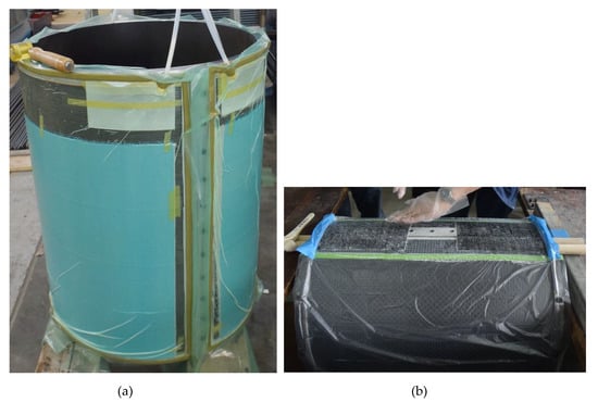
Figure 7.
Vacuum-assisted resin transfer molding (a) and hand-layup covering in the overlap area (b).
3.5. Shaking Table System and Dynamic Data Logger
The shaking table machine [43] used in the experiments was a three-dimensional shaking table system, SPT3D-15K-85L-50T. The actuators of the shaking table machine were SSV-850L, with a maximum acceleration of 19.6 m/s2 and maximum displacement of 400 mmP-P when there was no applied load. The maximum applied acceleration was decreased by the weight of the specimens and steel balls. Strain gauges were connected to a dynamic data logger to read and transfer strain values to the computer. The used data logger was the Multi-channel Dynamic Strainmeter DS-50A [44], which allowed for 50 connected channels with simultaneous sampling measurement. One accelerometer, called ARF-20A, which had a maximum acceleration measurement capacity of 20 m/s2 (a product of Tokyo Sokki Kenkyujo Co., Ltd, Tokyo, Japan), was stuck on the bottom steel plate to measure the real excitation with a high accuracy (see Figure 5).
3.6. Testing Procedures
Three specimens were used for the tests to investigate the strengthening effects of the CFRP layers for TSTs under a dynamic load: non-strengthened specimen, specimen strengthened using a 0° CFRP layer, and a specimen strengthened using a 0°/90° CFRP layer. Figure 8a shows the strengthened specimen after connecting it with the shaking table machine, and Figure 8b shows the specimen filled with steel balls. In the experiments, the steel balls had 1.2 mm diameters and the volume fraction of the steel balls was 58.8%. There were two height levels of steel balls in the investigation: 530 mm and 265 mm from the bottom steel plate, with the total weight of the steel balls being 600 kg and 300 kg, respectively.
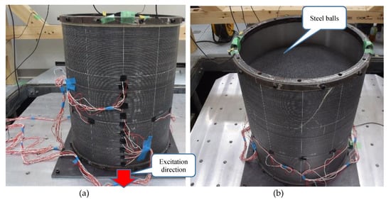
Figure 8.
Connecting the strengthened specimen with the shaking table (a) and filling steel balls (b).
There were three kinds of measurements. First, the static strain values of the specimens were measured after placing the steel balls into the tanks. As the steel balls were tested to replace a normal liquid and were expected to create higher internal pressures, these static strain values were used to compare them with theoretically calculated values and to confirm the applicability of the steel balls. In this step, the static strain values of non-strengthened and strengthened specimens were also compared to investigate the strengthening effect of the CFRP layers. In the next step, one-directional excitation was applied to all specimens that were filled to a 530 mm height of steel balls to consider the dynamic strain values and dynamic strengthening effects of CFRP layers on the performance of TSTs. Finally, one-directional excitation was applied to all the specimens that were filled to a 265 mm height of the steel balls to investigate the strengthening effects of CFRP layers for TSTs under the impact of sloshing. When the volume of the steel balls decreased to half, the maximum applied acceleration was increased and the sloshing of the steel balls occurred more easily. Each type of dynamic testing was conducted three times with the same conditions to investigate the variation of the experimental results. Table 8 shows the types of specimens being tested, the number of tests, and the notations for the specimens.

Table 8.
Summary of the types of tests for all the specimens.
3.7. Applied Dynamic Load
Horizontal one-directional excitation was applied for the specimens containing steel balls. Figure 9 and Figure 10 shows the input excitation using a 1.2755 Hz sine wave for the specimens that were filled to heights of 530 mm and 265 mm with steel balls, respectively. The vibration frequency of the model tank was increased by gradually increasing the input acceleration from 0 to 5.98 m/s2 for 530 mm filling height specimens and from 0 to 7.1 m/s2 for 265 mm filling height specimens.

Figure 9.
Input horizontal excitation for the 530 mm filling height specimens.

Figure 10.
Input horizontal excitation for the 265 mm filling height specimens.
4. Results and Discussion
4.1. Static Hoop Strains and Strengthening Effects of CFRP Layers on the Restraint of Static Strain Values
The static hoop strains of the specimens were recorded from strain gauges and were read using the data logger after placing all the steel balls into the tanks. These experimental values were compared to the theoretical calculations to estimate the replacement ability of steel balls for a normal liquid in dynamic experiments. The static hoop stress and hoop strain of the non-strengthened tanks could be calculated using Equations (19) and (20); meanwhile, the values of the strengthened specimens could be determined using Equations (21) and (22). The static hoop stress in the specimens in Equations (19) and (21) were calculated similarly with a normal liquid and the density of the normal liquid () being replaced by the density of the steel balls and multiplying it by the volume fraction of the steel balls (). Two parameters, and , have equivalent meanings because there are clearances between the steel balls, while there are almost no distances between liquid molecular particles.
In Equations (19)–(22), is the density of the steel balls ( = 7850 kg/m3), is the volume fraction of the steel balls ( = 58.8%), g is the acceleration due to gravity (g = 9.81 m/s2), hl is the distance from the free surface of the steel ball to the calculated point (see Figure 5), d is the inside diameter of the tanks (d = 588.8 mm), ta is the thickness of the aluminum shells, h is the total thickness of the CFRP-aluminum lamination, Ex is the circumferential elastic modulus of the aluminum tanks, E’x is the circumferential elastic modulus of the CFRP-aluminum lamination, is the hoop stress of the tanks, and is the hoop strain of the tanks.
Figure 11 shows the static hoop strains in the vertical direction (strain gauges 1 to 11) and Figure 12 shows these values in the horizontal direction (strain gauges 6 and 12 to 21). The experimental strain values were compared to the theoretical values. In Figure 11, z is the distance from the bottom steel plate to the calculated points (z = 0 at the bottom steel plate). It can be seen that the static hoop strains obtained from the experiments matched well with the theoretical calculations. A few differences were apparent at the top and bottom of the SNS specimen. This was because the SNS specimen was very thin; therefore, geometrical imperfection occurred after connecting the aluminum tank with the test rings (cylinder 1 and 2). The initially calculated results show that the hoop strain/stress created by the steel balls could be evaluated by using the theory of a normal liquid. Therefore, the use of steel balls, as a replacement for a normal liquid, is an equivalent way to create a higher internal pressure in testing.
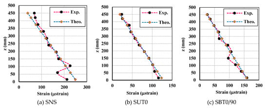
Figure 11.
Static hoop strains in the vertical direction (Exp: experimental result, Theo: theoretical calculation).
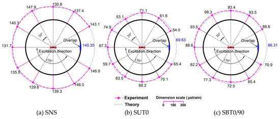
Figure 12.
Static hoop strains in the horizontal direction (μstrain).
Table 9 shows the effects of CFRP layers on the restraint of the static hoop strain values for all specimens that were tested. The values of static hoop strains decreased from about 35% to 62% when using 0°/90° CFRP strengthening, whereas these values decreased from 48% to 65% for 0° CFRP strengthening. The results of the two bottom strain gauges were excluded because the measured values were unstable, which were caused by geometrical imperfections.

Table 9.
The effects of the CFRP layers on the restraint of static and dynamic hoop strains.
4.2. Strengthening Effects of the CFRP Layers on the Restraint of Strain Values on the Tanks Under Dynamic Excitation
Figure 13 and Figure 14 show the sloshing behaviors of all the specimens that were filled to heights of 530 mm and 265 mm with steel balls, respectively. Sloshing only occurred in small amounts in the final seconds of the excitation in the 530 mm filling height specimens. However, sloshing occurred more strongly in the 265 mm filling height specimens because the maximum excitations were higher in these cases. Figure 15 and Figure 16 show the dynamic hoop strains in the vertical direction for all the specimens that were filled to 530 mm and 265 mm heights, respectively. Figure 17, Figure 18, Figure 19, Figure 20, Figure 21 and Figure 22 show the dynamic hoop strains in the horizontal direction for these specimens. The maximum values of the dynamic hoop strains in the horizontal direction were almost in the excitation direction. A small difference occurred for DUT0-530 and DBT0/90-530, where the maximum values of the dynamic hoop strains were on the right side of the excitation direction position (see Figure 18 and Figure 19). The difference was caused by the geometrical imperfections when installing the specimens and were confirmed by the values of the static strains (Figure 12) since the static strain values on the right side of the excitation direction position were also higher compared to the excitation direction position. However, these differences were very small and the maximum dynamic strain values could also be considered to be located in the excitation direction position for the DUT0-530 and DBT0/90-530 specimens. While the same experimental conditions were applied for the DNS-530, DUT0-530, and DBT0/90-530 specimens, the difference did not occur for DNS-530 specimens because the strain values were much higher in the DNS-530 specimen compared to the DUT0-530 and DBT0/90-530 specimens. Therefore, the maximum dynamic strain values could be seen in the excitation direction position for the DNS-530 specimen. The maximum values of the dynamic hoop strains in the horizontal direction were in the excitation direction for all 265 mm filling height specimens because the specimens were highly impacted by stronger sloshing.

Figure 13.
Sloshing behaviors for the 530 mm filling height specimens.

Figure 14.
Sloshing behaviors for the 265 mm filling height specimens.
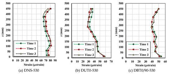
Figure 15.
Dynamic hoop strains in the vertical direction for the 530 mm filling height specimens.
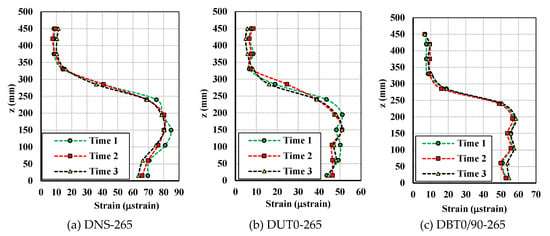
Figure 16.
Dynamic hoop strains in the vertical direction for the 265 mm filling height specimens.
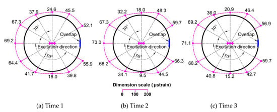
Figure 17.
Dynamic hoop strains in the horizontal direction (μstrain) for the DNS-530 specimen.
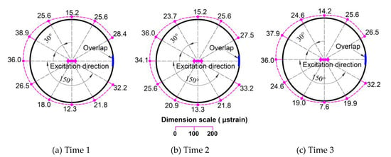
Figure 18.
Dynamic hoop strains in the horizontal direction (μstrain) for the DUT0-530 specimen.
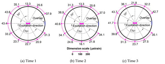
Figure 19.
Dynamic hoop strains in the horizontal direction (μstrain) for the DBT0/90-530 specimen.
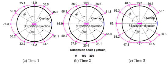
Figure 20.
Dynamic hoop strains in the horizontal direction (μstrain) for the DNS-265 specimen.
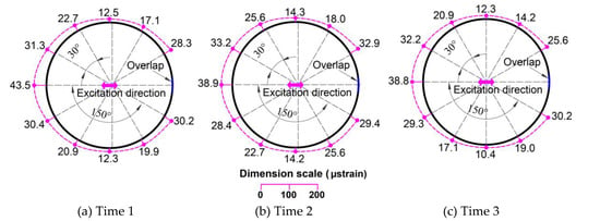
Figure 21.
Dynamic hoop strains in the horizontal direction (μstrain) for the DUT0-265 specimen.
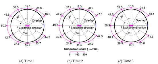
Figure 22.
Dynamic hoop strains in the horizontal direction (μstrain) for the DBT0/90-265 specimen.
The effects of the CFRP layers on the restraint of the dynamic hoop strain values for all specimens are also shown in Table 9. The dynamic strain values are the average values of the three tests. When strengthened using CFRP layers, the restraint effects of the dynamic hoop strains in the tank were up to 54.43% with a 0° CFRP layer and to 42.36% with a 0°/90° CFRP layer. A 0° CFRP layer was shown to be more effective than the 0°/90° CFRP layer at decreasing dynamic strains. As can be seen in Figure 15, the dynamic strain distribution in the DBT0/90-530 specimen had a similar behavior to the DNS-530 specimen. The dynamic strain values at the top and bottom were equal in each specimen and were larger than the strain values in the middle sections. High values for the dynamic strain were obtained at the top because of the impact of sloshing. The dynamic strain behavior of the DUT0-530 specimen was different from other specimens when the dynamic strains were smaller at the top of the specimen. Therefore, the strengthening effect of the 0° CFRP layer against the impacts of sloshing was also better than the 0°/90° CFRP layer.
To investigate the strengthening effects of CFRP for TSTs under the impact of sloshing, 265 mm filling height specimens were used because the sloshing occurred more strongly at this height level of steel balls. Table 9 shows the strain decrease levels in the strengthened specimens under the impact of sloshing. The strengthening effects were up to 43.23% for the specimen strengthened using the 0° CFRP layer and to 32.77% when using 0°/90° CFRP strengthening. Therefore, the 0° CFRP layer had higher strengthening effects on the restraint of dynamic hoop strains under dynamic loads.
5. Conclusions
In this paper, the strengthening effects of CFRP layers for thin-walled storage tanks under dynamic loads were experimentally investigated. The main conclusions are as follows.
- Small diameter steel balls could be used as a suitable solution to replace a normal liquid in the experiments of small-scale specimens under dynamic loads. Good correspondences were found between static hoop strains obtained from experiments and the values that were calculated using theory. In this way, higher internal pressures could be created for the small-scale tanks containing materials inside. The testing method for small-scale tanks containing a high-density material under a dynamic load was developed with the similarity rules for small-scale models, making the testing easier to perform with small-scale models.
- The CFRP layers could restrain both static and dynamic hoop strains in TSTs, especially for the 0° CFRP layer. The restraint levels of static strains could be up to 65% for the 0° CFRP layer and 62% for the 0°/90° CFRP layer. The restraint of the static strains could be calculated exactly using theoretical equations. Additionally, the 0° CFRP layer had better strengthening effects than the 0°/90° CFRP layer in dynamic tests (a 54% strain restraint compared with 42%).
- Both the 0° and 0°/90° CFRP layers proved the strengthening effects of TSTs under the impact of sloshing by effectively decreasing the dynamic hoop strains. Better strengthening effects were also be found using the 0° CFRP layer.
Author Contributions
All authors have made a substantial contribution to this study. N.P.V. designed the experimental parameters, analyzed the data, and wrote the paper. Y.K. performed dynamic tests and reviewed the paper. Y.M. provided the concept and design of the study, along with writing review and editing. All authors have read and agreed to the published version of the manuscript.
Funding
This work was supported by JSPS (Japan Society for the Promoton of Science) KAKENHI grant number 17K06640.
Conflicts of Interest
The authors declare no conflict of interest.
References
- Architectural Institute of Japan (AIJ). Reconnaissance Report on the 2010 Chile Off Maule Earthquake and Reconnaissance report on the 2011 New Zealand Christchurch Earthquake; Architectural Institute of Japan: Tokyo, Japan, 2012. [Google Scholar]
- Architectural Institute of Japan (AIJ). Preliminary Reconnaissance Report of the 2011 Tohoku-Chiho Taiheiyo-Oki Earthquake; Architectural Institute of Japan: Tokyo, Japan, 2012. [Google Scholar]
- American Lifelines Alliance. Seismic Fragility Formulations for Water Systems; ASCE, Part1-Guideline, Part-2 Appendices; American Society of Civil Engineers (ASCE): Reston, VI, USA, 2001. [Google Scholar]
- Architectural Institute of Japan (AIJ). Design Recommendation for Storage Tanks and Their Supports; Architectural Institute of Japan: Tokyo, Japan, 2010. [Google Scholar]
- Maekawa, A. Recent Advances in Seismic Response Analysis of Cylindrical Liquid Storage Tanks. In Earthquake-Resistant Structures - Design, Assessment and Rehabilitation; Abbas, M., Ed.; InTechOpen: London, UK, 2012. [Google Scholar] [CrossRef][Green Version]
- National Aeronautics and Space Administration. Buckling of Thin-walled Circular Cylinders; NASA Space Vehicle Design Criteria, NASA SP-8007; NASA: Washington, DC, USA, 1968. [Google Scholar]
- Teng, J.G. Buckling of thin shells: Recent advances and trends. Appl. Mech. Rev. 1996, 49, 263–274. [Google Scholar] [CrossRef]
- Moghaddam, H.; Sangi, S. Elephant’s Foot Buckling of Cylindrical Steel Storage Tanks Subjected to Earthquake Excitation. In Proceedings of the 6th National Congress on Civil Engineering, Semnan University, Semnan, Iran, 26–27 April 2011. [Google Scholar]
- Shih, C.F. Failure of Liquid Storage Tanks due to Earthquake Excitation; Earthquake Engineering Research Laboratory – California Institution of Technology: California, CA, USA, 1981. [Google Scholar]
- Handam, F.H. Seismic behavior of cylindrical steel storage tanks. J. Constr. Steel Res. 2000, 53, 307–333. [Google Scholar] [CrossRef]
- Virella, J.C.; Godoy, L.A.; Suárez, L.E. Dynamic buckling of anchored steel tanks subjected to horizontal earthquake excitation. J. Constr. Steel Res. 2006, 62, 521–531. [Google Scholar] [CrossRef]
- Xiao, T.L.; Qui, H.X.; Li, J.L. Seismic Behaviors of Concrete Beams Reinforced with Steel-FRP Composite Bars under Quasi-Static Loading. Appl. Sci. 2018, 8, 1913. [Google Scholar] [CrossRef]
- Guo, R.; Cai, L.; Hino, S.; Wang, B. Experimental Study on Shear Strengthening of RC Beams with an FRP Grid-PCM Reinforcement Layer. Appl. Sci. 2019, 9, 2984. [Google Scholar] [CrossRef]
- Lee, K.S.; Lee, B.Y.; Seo, S.Y. A Seismic Strengthening Technique for Reinforced Concrete Columns Using Sprayed FRP. Polymers 2016, 8, 107. [Google Scholar] [CrossRef] [PubMed]
- Napoli, A.; Realfonzo, R. RC Columns Strengthened with Novel CFRP Systems: An Experimental Study. Polymers 2015, 7, 2044–2060. [Google Scholar] [CrossRef]
- Zhao, X.L.; Zhang, L. State-of-the-art review on FRP strengthened steel structures. Eng. Struct. 2007, 29, 1808–1823. [Google Scholar] [CrossRef]
- Neale, K.W. FRP for structural rehabilitation: A survey of recent progress. Progr. Struct Eng. Mater. 2000, 2, 133–138. [Google Scholar] [CrossRef]
- Harries, K.; Peck, A.J.; Abraham, E.J. Enhancing stability of structural steel sections using FRP. Thin Wall Struct. 2009, 47, 1092–1101. [Google Scholar] [CrossRef]
- Miller, T.C.; Chajes, M.J.; Mertz, D.R.; Hastings, J.N. Strengthening of a steel bridge girder using CFRP plates. J. Bridge Eng. 2001, 6, 514–522. [Google Scholar] [CrossRef]
- Seica, M.V.; Packer, J.A. FRP materials for the rehabilitation of tubular steel structures for underwater applications. Compos. Struct. 2007, 80, 440–450. [Google Scholar] [CrossRef]
- Cadei, J.M.C.; Stratford, T.J.; Hollaway, L.C.; Duckett, W.H. C595-Strengthening Metallic Structures Using Externally Bonded Fiber-reinforced Composites; CIRIA: London, UK, 2004. [Google Scholar]
- Haedir, J.; Zhao, X.L. Design of short CFRP-reinforced steel tubular columns. J. Constr. Steel Res. 2011, 67, 497–509. [Google Scholar] [CrossRef]
- Al-Azzawi, Z.; Stratford, T.; Rotter, M.; Bisby, L. FRP Shear Strengthening of Thin-Walled Plate Girder Web Panels Subjected to Cyclic Loading. In Proceedings of the PROTECT 2015, East Lansing, MI, USA, 28–30 June 2015; pp. 350–359. [Google Scholar]
- Al-Azzawi, Z.; Stratford, T.; Rotter, M.; Bisby, L. Buckling Strength of Slender Steel Plates Stiffened with Corrugated FRP Panels. In Proceedings of the ACIC 2015, Cambridge, UK, 9–11 September 2015; pp. 201–206. [Google Scholar]
- Khazaei Poula, M.; Nateghi-Alahib, F.; Zhao, X.L. Experimental testing on CFRP strengthened thin steel plates under shear loading. Thin-Walled Struct. 2016, 109, 217–226. [Google Scholar] [CrossRef]
- Bambach, M.R.; Jama, H.H.; Elchalakani, M. Axial capacity and design of thin-walled steel SHS strengthened with CFRP. Thin Wall Struct. 2009, 47, 1112–1121. [Google Scholar] [CrossRef]
- Batikha, M.; Chen, J.F.; Rotter, J.M.; Teng, J.G. Strengthening metallic cylindrical shells against elephant’s foot buckling with FRP. Thin Wall Struct. 2009, 47, 1078–1091. [Google Scholar] [CrossRef]
- Batikha, M. Strengthening of Thin Metallic Cylindrical Shells Using Fiber Reinforced Polymers. Ph.D. Thesis, The University of Edinburgh, Edinburgh, UK, 2008. [Google Scholar]
- Vakili, M.; Showkati, H. Elephant foot buckling and retrofitting of steel thin walled cylindrical shells using FRP composite materials. J. Civ. Environ. Eng. 2016, 45, 109–119. [Google Scholar]
- Bhetwal, K.K.; Yamada, S. Effects of CFRP reinforcements on the buckling behavior of thin-walled steel cylinders under compression. Int. J. Struct. Stab. Dyn. 2012, 12, 131–151. [Google Scholar] [CrossRef]
- Matsumoto, Y.; Matsui, T.; Nakamura, H.; Tsujioka, A.; Hasegawa, C.; Matsuura, S.; Endo, Y. Compressive characteristics of thin-walled steel cylinder strengthened by CFRP. In Proceedings of the 12th International Symposium on Fiber Reinforced Polymers for Reinforced Concrete Structures & the 5th Asia-Pacific Conference on Fiber Reinforced Polymers in Structures, Nanjing, China, 14–16 December 2015. [Google Scholar]
- Nhut, P.V.; Matsumoto, Y. The Effects of Carbon Fiber Reinforced Polymer Strengthening on Cylindrical Steel Storage Tanks under Bending Shear Load. IOP Conf. Ser. Mater. Sci. Eng. 2018, 371, 012025. [Google Scholar] [CrossRef]
- High-Performance Carbon Fiber Torayca, Torayca Cloth. Available online: https://www.torayca.com/en/download/pdf/cloth.pdf (accessed on 4 April 2020).
- Mieda, G.; Nakamura, H.; Matsui, T.; Ochi, Y.; Matsumoto, Y. Mechanical behavior of CFRP on steel surface molded and bonded by vacuum-assisted resin transfer molding technology. SN Appl. Sci. 2019, 1, 601. [Google Scholar] [CrossRef]
- Kaw, K.A. Mechanics of Composite Materials; CRC Taylor & Francis: Boca Raton, FL, USA, 2006. [Google Scholar]
- American Petroleum Institute. API 650: Welded Steel Tanks for Oil Storage; American Petroleum Institute-195.132(b)(3): Washington, DC, USA, 2012. [Google Scholar]
- ITTC-Recommended Procedures and Guidelines. ITTC Quality System Manual-Recommended Procedures and Guidelines – Sloshing Model Tank; ITTC: Zürich, Switzerland, 2017. [Google Scholar]
- Heller, V. Scale effects in physical hydraulic engineering models. J. Hydraul. Res. 2011, 49, 293–306. [Google Scholar] [CrossRef]
- Praveen, K.M.; Thomas, W.; Martin, W. Simple Procedure for Seismic Analysis of Liquid-Storage Tanks. Struct. Eng. Int. 2000, 10, 197–201. [Google Scholar] [CrossRef]
- Uddin, N.; Vaidya, U.; Shohel, M.; Perez, J.C.S. Cost-effective bridge girder strengthening using vacuum-assisted resin transfer molding (VARTM). Adv. Compos. Mat. 2004, 13, 255–281. [Google Scholar] [CrossRef]
- Abusrea, M.R.; Han, S.W.; Arakawa, K.; Choi, N.S. Bending strength of CFRP laminated adhesive joints fabricated by vacuum-assisted resin transfer molding. Compos. Part B 2019, 156, 8–16. [Google Scholar] [CrossRef]
- Yalcinkaya, M.A.; Sozer, E.M.; Altan, M.C. Fabrication of high quality composites laminates by pressurized and heated-VARTM. Compos. Part A 2017, 102, 336–346. [Google Scholar] [CrossRef]
- SPT3D Series [3-Axis Simultaneous Seismic Shaking Table], San-Esu Co, Ltd., Japan. Available online: http://www.san-esu.com/product040.html (accessed on 4 April 2020).
- Multi-Channel Dynamic Strainmeter DS-50A, Tokyo Measuring Instruments Laboratory Co., Ltd., Tokyo, Japan. Available online: https://tml.jp/e/product/instrument/digitaltype.html (accessed on 4 April 2020).
© 2020 by the authors. Licensee MDPI, Basel, Switzerland. This article is an open access article distributed under the terms and conditions of the Creative Commons Attribution (CC BY) license (http://creativecommons.org/licenses/by/4.0/).