Abstract
The present paper reports the preparation of multilayer protonic ceramic fuel cells (PCFCs) using a single sintering step. The success of this fabrication approach is due to two main factors: the rational choice of chemically and mechanically compatible components, as well as the selection of a convenient preparation (tape calendering) method. The PCFCs prepared in this manner consisted of a 30 µm BaCe0.5Zr0.3Dy0.2O3–δ (BCZD) electrolyte layer, a 500 μm Ni–BCZD supporting electrode layer and a 20 μm functional Pr1.9Ba0.1NiO4+δ (PBN)–BCZD cathode layer. These layers were jointly co-fired at 1350 °C for 5 h to reach excellent gas-tightness of the electrolyte and porous structures for the supported and functional electrodes. The adequate fuel cell performance of this PCFC design (400 mW cm−2 at 600 °C) demonstrates that the tape calendering method compares well with such conventional laboratory PCFC preparation techniques such as co-pressing and tape-casting.
1. Introduction
Protonic ceramic fuel cells (PCFCs) form a class of fuel cells (FCs) providing highly efficient and economically advantageous chemical-to-electrical energy conversion at elevated temperatures [1,2,3,4,5]. A proton-conducting electrolyte membrane as a PCFC’s heart transports proton charge carriers with high levels of ionic conductivity compared with those of oxygen-ionic electrolytes of the traditional solid oxide fuel cells (SOFCs), owing to the corresponding high mobility/concentration of protons [6,7,8,9]. This allows the operational temperatures of the FCs to be decreased by ~100–300 °C to reach low- (300–500 °C) and intermediate-temperature (500–700 °C) ranges [10,11,12,13]. As a consequence, temperature-determined processes (electrode sintering, material interaction, thermal misbalance, poisoning) occurring in PCFCs become less adverse factors in terms of their effect on overall performance and FC degradation over a long-term period of operation [14,15,16].
Conventional FCs, including SOFCs and PCFCs, are comprised of a minimum of three functional components (layers): electrolyte, cathode and anode. Each layer requires its own unique processing regime [17,18,19]. In terms of the electrode-supported configuration of FCs, a thin electrolyte layer is formed onto a Ni-based anode and then these two layers are jointly fired at high temperatures to form a half-cell, combining the porous anode substrate and dense electrolyte. The next step consists of cathode formation onto the electrolyte surface followed by its sintering at a lower temperature, which produces the final FC [20,21,22,23]. As can be seen, the provided scheme includes several temperature regimes along with their various parameters (temperatures, heating/cooling rates, soaking times). Since the multi-stage preparation process of conventional FCs is time-, energy- and resource-intensive, the possibility of transition to a single-stage preparation process is of high interest.
The one-step sintering of FCs represents an important technological strategy, allowing the entire FC to be produced using a single temperature regime. This strategy has recently been successfully used in the fabrication of both SOFCs [24,25] and PCFCs [26,27]. However, it should be noted that the FCs in the referenced studies were prepared by means of a co-pressing method requiring high pressing pressures. Although such a method can be quite easily used for fabricating the single cells with a small size, its adaptation for large-scale production presents severe challenges. Therefore, as an alternative approach, we herein propose a tape calendering method as a simple, scalable and efficient means for one-step fabrication of PCFCs. The possibility of one-step fabrication is based on our recent achievements in materials science (the selection of chemically and thermally compatible materials [28,29]) and technological (the rational parameter tuning of the tape calendering method [30,31]) fields.
2. Materials and Methods
In the present work, the tape calendering method was utilised to prepare the entire PCFC, which was then sintered in a single step. In order to achieve successful results, it was necessary to take several factors into consideration: (a) the electrolyte must be fully densified, while the electrodes should have a sufficient porosity; (b) all the functional materials need to exhibit similar thermomechanical properties; (c) no significant chemical interactions should occur at the anode/electrolyte and electrolyte/cathode interfaces. Taking these limitations into account, BaCe0.5Zr0.3Dy0.2O3–δ + 0.5 wt% CuO (BCZD) was selected as a proton-conducting electrolyte [28,32], while Pr1.9Ba0.1NiO4+δ (PBN) was used to form a cathode [29]. In detail, BCZD is characterised by good protonic conductivity levels, coupled with a high chemical stability in highly moisturised atmospheres. A small amount of copper oxide was added as an aid [33,34] to promote BCZD sinterability. PBN was selected due to its good chemical and thermal compatibilities with BCZD, even at 1350 °C [29].
The PCFC was fabricated according to the principal scheme presented in Figure 1. First, four individual powders were prepared for the corresponding functional layers:
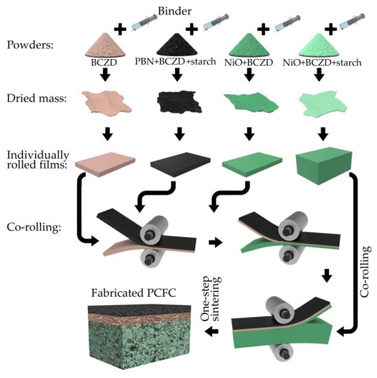
Figure 1.
Principal scheme of protonic ceramic fuel cells (PCFCs) fabricated by tape calendering method and one-step sintering.
- An anode supporting layer (ASL) was prepared by thorough the mixing of the NiO, BCZD and pore former (starch) powders in a weight ratio of 60:40:20;
- The anode functional layer (AFL) consisted of NiO and BCZD (without starch) powders mixed in a weight ratio of 55:45;
- An electrolyte layer (EL) was formed using the BCZD powder only;
- A cathode functional layer (CFL) was prepared by thorough mixing of the PBN, BCZD and starch in a weight ratio of 70:30:10.
The second stage included the preparation of mixtures of the corresponding powders in an organic binder (components and their concentrations are provided elsewhere [30]). These mixtures were dried overnight to remove evaporating solvents (acetone, benzene). The dried residues were rolled using a Durtson rolling mill to fabricate the corresponding film layers with the required thicknesses. Since the minimal gap between the rolls was ~100 μm, the PCFC with a 30 μm-thick electrolyte was prepared by rolling the 100 μm-thick films several times: first EL with CFL, and then the obtained film with AFL to produce the 100 μm-thick structure AFLǀELǀCFL. The green ASLǀAFLǀELǀCFL cell was prepared by co-rolling the latter film with a 500 μm-thick ASL film using a larger roll gap. Finally, the green cell was co-sintered according to the following regime: heating up to 600 °C with a heating rate of 1 °C min−1, heating up to 1350 °C with a heating rate of 3 °C min−1, isothermal soaking at 1350 °C for 5 h, and cooling down to room temperature with a cooling rate of 3 °C min−1.
Scanning electron microscopy (SEM, TESCAN MIRA 3 LMU microscope, TESCAN, Czech Republic) coupled with energy-dispersive X-ray spectroscopy (EDX, INCA Energy 350 microanalysis system, Oxford Instruments Analytical, UK) was used to analyse the microstructural parameters of the PCFC.
The fabricated PCFC was electrochemically characterised utilising a complex of Amel 2550 potentiostat/galvanostat (Amel, Italy) and a Materials M520 frequency material response analyser (Amel, Italy) to obtain data on volt–ampere and impedance dependences. The impedance spectra were collected in a frequency range of 3·104–5·10−2 Hz with an acceleration voltage of 30 mV and a cell bias corresponding to open circuit voltage (OCV) or maximal power density (Pmax) conditions. Humid air with water vapour partial pressure (pH2O) of 0.30 atm was used as an oxidant, while wet hydrogen (pH2O = 0.03 atm) was used as a fuel. The required pH2O values were achieved by feeding the corresponding gases through the water bubbler thermostated at certain temperatures (69 and 25 °C, respectively). The electrochemical characterisation of the PCFC was carried out at temperatures varying from 550 to 700 °C; the cell was equilibrated for 1 h after each temperature change.
3. Results and Discussion
The electrode-supported PCFC fabricated via the tape calendering method followed by one-step sintering and was characterised in terms of its microstructure. According to Figure 2, the thicknesses of AFL, EL and CFL were estimated to be 40, 30 and 20 μm, respectively; while the thickness of the entire PCFC was ~600 μm. The layers exhibit essential properties, including a dense state for the electrolyte and a porous structure for the functional cathode and anode; moreover, there is a good interface contact (adhesion) for both AFL/EL and EL/CFL couples. These results imply that the combination of the used methods, temperature regimes and material compositions was quite well optimised. Here we should stress that the present example of an asymmetric PCFC, co-sintered during a single stage, represents one of the initial reports, achieving successful results comparable to those obtained via conventional sintering at such high temperatures as 1350 °C. In other cases [26,27], asymmetric-type PCFCs were fabricated at lower sintering temperatures (below 1250 °C), which, as a rule, are insufficient for the required densification of Zr-containing (especially, Zr-enriched) BaCeO3 materials.
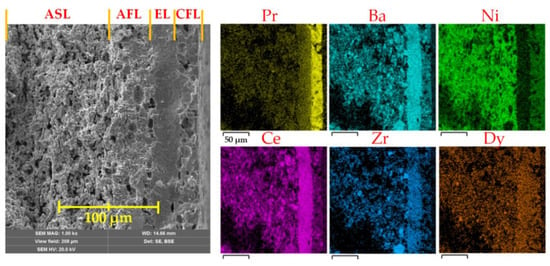
Figure 2.
Cross-section of the fabricated PCFC with the 30 μm-thick BaCe0.5Zr0.3Dy0.2O3–δ (BCZD) electrolyte and corresponding energy-dispersive X-ray spectroscopy (EDX) analysis.
Figure 3 shows the volt–ampere (U–j) characteristics of the PCFC recorded under OCV conditions (when j = 0) to ~100 mV with a voltage step of 25 mV. The high current density conditions, corresponding to a voltage range of 0–100 mV, were used in order to prevent significant heating of the cell. Analysing the free-current conditions, the cell generates OCVs varying from 1.040 V at 550 °C to 0.935 V at 700 °C. At low temperatures, these OCVs are very close to the theoretical values (1.056 V at 550 °C), but start to deviate from them (by ~80 mV at 700 °C) at higher temperatures, indicating the electron transport of the BCZD membrane [35]. Here, the theoretical levels were estimated on the basis of a Nernstian equation for a pure protonic conductor (EH = RT/2F·ln[p′H2/p″H2]). The PCFC load results in the generation of Pmax, which increases from 290 mW cm−2 at 550 °C to 470 mW cm−2 at 700 °C.
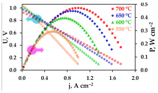
Figure 3.
Volt–ampere and power density curves for the fabricated PCFC at different temperatures.
The EIS analysis was further utilised to reveal the main factors affecting the overall fuel cell performance. For this purpose, the impedance spectra were recorded in two conditions. One of these corresponds to the conventional measurements at OCV, while the other is related to realising Pmax. Despite the Pmax conditions describing the real operation of a fuel cell, this function has yet to be analysed in detail in the literature.
The EIS results presented in Figure 4 indicate that the spectra have different shapes depending on the measurement temperatures and/or cell bias. In detail, at least three parts (described by RQ elements, where R is the resistance, Q is the constant phase element) can be clearly distinguished at low temperatures; these merge to enable the detection of at least two (low- and high-frequency) processes at higher temperatures. Due to the revealed complexity, only the overall polarisation resistance (Rp) was calculated in order to analyse the electrochemical behaviour of the PCFC electrodes. Considering the temperature effect (Figure 4a), a typical decrease in both ohmic resistance (Ro) and Rp is observed, which is in line with the thermo-activated nature of ongoing processes. However, when the bias is changed from OCV conditions to PCFC load, the following interesting tendencies occur: Ro attains almost constant values, but the Rp level grows more noticeably, implying a deterioration in the electrochemical behaviour. The latter agrees with a number of studies [36,37,38], which report similar Rp growth with decreasing cell bias. The observed Rp deterioration might either be associated with a decrease in the p-type electronic conductivity of the proton-conducting electrolyte, thus providing a lower current distribution at the EL/CFL interface [39,40], or with an increase in the concentration type of Rp taking place at high current densities [41,42].
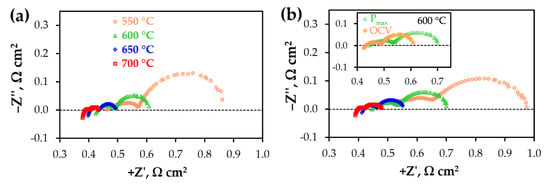
Figure 4.
Typical impedance spectra of the fabricated PCFC at different temperatures under conditions corresponding to open circuit voltage (OCV) (a) and Pmax (b).
Figure 5 depicts the absolute values of Ro, Rp, Rt along with their ratio. As can be seen, the overall PCFC resistance is equal to 0.86 Ω cm2 at 550 °C and 0.43 Ω cm2 at 700 °C for the OCV conditions. At the same time, the Rp contribution is lower than 50% for all measured temperatures; this indicates that the parameters of the electrolyte (resistance and, especially, thickness) are dominant factors affecting the performance of the PCFC. When the cell bias corresponds to the Pmax conditions, the overall PCFC resistance rises to 0.97 Ω cm2 at 550 °C and 0.48 Ω cm2 at 700 °C due to an increase in Rp (its contribution attains ~51% at 550 °C and 16% at 700 °C). According to the obtained data, further research efforts should be aimed at obtaining an improvement in electrode behaviour under load rather than the conventional OCV conditions.
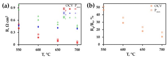
Figure 5.
Temperature dependences of Rt, Rp and Ro resistances (a) as well as a ratio of Rp/Rt (b) at different fuel cell conditions (OCV or Pmax).
To illustrate the prospect of the tape calendering method as a means of fabricating PCFCs via a one-step procedure, a comparative analysis was performed (Table 1). As can be seen, the rational selection of the functional materials, as well as the utilisation of convenient laboratory technology, allow PCFC fabrication with promising performance across the intermediate temperature range. It should be noted that the effect of ohmic resistance is excluded from consideration in order to provide a clear relationship between the polarisation resistance and power density. From this viewpoint, the achieved electrode activity competes with the electrochemical activity of electrodes as prepared by other methods, although the number of temperature regimes is reduced to only one.

Table 1.
Different PCFCs and their out-put performance at 600 °C 1.
5. Conclusions
The present work summarises technological advances in the fabrication of electrode-supported protonic ceramic fuel cells (PCFCs) using a single temperature regime. This achievement was realised due to the utilisation of the tape calendering (co-rolling) method recently adopted for solid oxide fuel cells based on proton-conducting electrolyte membranes. The PCFC fabricated in this way demonstrated both gas-tightness (1.03 V at 600 °C in the current-free mode) and high performance (~400 mW cm−2 at 600 °C) as a result of achieving the required morphological properties—full densification of the electrolyte and sufficient electrode porosity.
Author Contributions
Conceptualization, J.L. and D.M.; methodology, J.L.; software, A.T. and N.D.; validation, D.M.; formal analysis, J.L., A.T. and N.D.; investigation, Y.L., A.T. and N.D.; resources, J.L., A.T., N.D. and D.M.; data curation, D.M.; writing—original draft preparation, D.M.; writing—review and editing, D.M.; visualization A.T. and N.D.; supervision, D.M.; project administration, D.M.; funding acquisition, D.M. All authors have read and agreed to the published version of the manuscript.
Funding
This work was supported by the Russian Foundation for Basic Research, grant number 18-38-20063.
Acknowledgments
The authors thank G. Vdovin for his assistance in experiments. The SEM characterisation was carried out at the Shared Access Centre “Composition of Compounds” of the Institute of High-Temperature Electrochemistry [51].
Conflicts of Interest
The authors declare no conflict of interest.
References
- Mojaver, P.; Chitsaz, A.; Sadeghi, M.; Khalilarya, S. Comprehensive comparison of SOFCs with proton-conducting electrolyte and oxygen ion-conducting electrolyte: Thermoeconomic analysis and multi-objective optimisation. Energy Convers. Manag. 2020, 205, 112455. [Google Scholar] [CrossRef]
- Dubois, A.; Ricote, S.; Braun, R.J. Benchmarking the expected stack manufacturing cost of next generation, intermediate-temperature protonic ceramic fuel cells with solid oxide fuel cell technology. J. Power Sources 2017, 369, 65–77. [Google Scholar] [CrossRef]
- Meng, Y.; Gao, J.; Zhao, Z.; Amoroso, J.; Tong, J.; Brinkman, K.S. Recent progress in low-temperature proton-conducting ceramics. J. Mater. Sci. 2019, 54, 9291–9312. [Google Scholar] [CrossRef]
- Kim, J.; Sengodan, S.; Kim, S.; Kwon, O.; Bu, Y.; Kim, G. Proton conducting oxides: A review of materials and applications for renewable energy conversion and storage. Renew. Sustain. Energy Rev. 2019, 109, 606–618. [Google Scholar] [CrossRef]
- Rashid, N.L.R.M.; Samat, A.A.; Jais, A.A.; Somalu, M.R.; Muchtar, A.; Baharuddin, N.A.; Isahak, W.N.R.W. Review on zirconate-cerate-based electrolytes for proton-conducting solid oxide fuel cell. Ceram. Int. 2019, 45, 6605–6615. [Google Scholar] [CrossRef]
- Xu, L.; Jiang, D.E. Understanding hydrogen in perovskites from first principles. Comput. Mater. Sci. 2020, 174, 109461. [Google Scholar] [CrossRef]
- Lei, Z.; Jing, J.; Pang, J.; Hu, R.; Shi, X.; Yang, Z.; Peng, S. Highly conductive proton-conducting electrolyte with a low sintering temperature for electrochemical ammonia synthesis. Int. J. Hydrogen Energy 2020, 45, 8041–8051. [Google Scholar] [CrossRef]
- Tarasova, N.; Animitsa, I.; Galisheva, A.; Korona, D. Incorporation and conduction of protons in Ca, Sr, Ba-doped BaLaInO4 with Ruddlesden-Popper structure. Materials 2019, 12, 1668. [Google Scholar] [CrossRef]
- Shlyakhtina, A.V.; Abrantes, J.C.C.; Gomes, E.; Lyskov, N.V.; Konysheva, E.Y.; Chernyak, S.A.; Shcherbakova, L.G. Evolution of oxygen–ion and proton conductivity in Ca-Doped Ln2Zr2O7 (Ln = Sm, Gd), located near pyrochlore–fluorite phase boundary. Materials 2019, 12, 2452. [Google Scholar] [CrossRef]
- Bi, L.; Da’as, E.H.; Shafi, S.P. Proton-conducting solid oxide fuel cell (SOFC) with Y-doped BaZrO3 electrolyte. Electrochem. Commun. 2017, 80, 20–23. [Google Scholar] [CrossRef]
- Choi, S.; Kucharczyk, C.J.; Liang, Y.; Zhang, X.; Takeuchi, I.; Ji, H.I.; Haile, S.M. Exceptional power density and stability at intermediate temperatures in protonic ceramic fuel cells. Nat. Energy 2018, 3, 202–210. [Google Scholar] [CrossRef]
- Duan, C.; Kee, R.; Zhu, H.; Sullivan, N.; Zhu, L.; Bian, L.; O’Hayre, R. Highly efficient reversible protonic ceramic electrochemical cells for power generation and fuel production. Nat. Energy 2019, 4, 230–240. [Google Scholar] [CrossRef]
- An, H.; Lee, H.W.; Kim, B.K.; Son, J.W.; Yoon, K.J.; Kim, H.; Lee, J.H. A 5 × 5 cm2 protonic ceramic fuel cell with a power density of 1.3 W cm−2 at 600 °C. Nat. Energy 2018, 3, 870–875. [Google Scholar] [CrossRef]
- Kasyanova, A.V.; Tarutina, L.R.; Rudenko, A.O.; Lyagaeva, Y.G.; Medvedev, D.A. Ba(Ce,Zr)O3-based electrodes for protonic ceramic electrochemical cells: Towards highly compatible functionality and triple-conducting behaviour. Russ. Chem. Rev. 2020, 89. in press. [Google Scholar] [CrossRef]
- Fan, L.; Zhu, B.; Su, P.C.; He, C. Nanomaterials and technologies for low temperature solid oxide fuel cells: Recent advances, challenges and opportunities. Nano Energy 2018, 45, 148–176. [Google Scholar] [CrossRef]
- Gao, Z.; Mogni, L.V.; Miller, E.C.; Railsback, J.G.; Barnett, S.A. A perspective on low-temperature solid oxide fuel cells. Energy Environ. Sci. 2016, 9, 1602–1644. [Google Scholar] [CrossRef]
- Shu, L.; Sunarso, J.; Hashim, S.S.; Mao, J.; Zhou, W.; Liang, F. Advanced perovskite anodes for solid oxide fuel cells: A review. Int. J. Hydrogen Energy 2019, 44, 31275–31304. [Google Scholar] [CrossRef]
- Medvedev, D. Trends in research and development of protonic ceramic electrolysis cells. Int. J. Hydrogen Energy 2019, 44, 26711–26740. [Google Scholar] [CrossRef]
- Wang, F.; Lyu, Y.; Chu, D.; Jin, Z.; Zhang, G.; Wang, D. The electrolyte materials for SOFCs of low-intermediate temperature. J. Mater. Sci. Technol. 2019, 35, 1551–1562. [Google Scholar] [CrossRef]
- Zakaria, Z.; Awang Mat, Z.; Abu Hassan, S.H.; Boon Kar, Y. A review of solid oxide fuel cell component fabrication methods toward lowering temperature. Int. J. Energy Res. 2019, 44, 594–611. [Google Scholar] [CrossRef]
- Carneiro, J.; Nikolla, E. Nanoengineering of solid oxide electrochemical cell technologies: An outlook. Nano Res. 2019, 12, 2081–2092. [Google Scholar] [CrossRef]
- Lyu, Y.; Wang, F.; Wang, D.; Jin, Z. Alternative preparation methods of thin films for solid oxide fuel cells. Mater. Technol. 2019, 35, 212–227. [Google Scholar] [CrossRef]
- Kalinina, E.G.E.; Pikalova, E.Y. New trends in the development of electrophoretic deposition method in the solid oxide fuel cell technology: Theoretical approaches, experimental solutions and development prospects. Russ. Chem. Rev. 2019, 88, 1179. [Google Scholar] [CrossRef]
- Zhang, L.; Lan, R.; Cowin, P.I.; Tao, S. Fabrication of solid oxide fuel cell based on doped ceria electrolyte by one-step sintering at 800 °C. Solid State Ion. 2011, 203, 47–51. [Google Scholar] [CrossRef]
- Zhang, L.; Tao, S. An intermediate temperature solid oxide fuel cell fabricated by one step co-press-sintering. Int. J. Hydrogen Energy 2011, 36, 14643–14647. [Google Scholar] [CrossRef]
- Wang, B.; Bi, L.; Zhao, X.S. Fabrication of one-step co-fired proton-conducting solid oxide fuel cells with the assistance of microwave sintering. J. Eur. Ceram. Soc. 2018, 38, 5620–5624. [Google Scholar] [CrossRef]
- Sun, W.; Tao, Z.; Shi, Z.; Yan, L.; Zhu, Z.; Liu, W. Fabrication of BaZr0.1Ce0.7Y0.2O3–δ-based proton-conducting solid oxide fuel cells co-fired at 1150 °C. Fuel Cells 2010, 10, 1108–1113. [Google Scholar] [CrossRef]
- Lyagaeva, J.; Medvedev, D.; Pikalova, E.; Plaksin, S.; Brouzgou, A.; Demin, A.; Tsiakaras, P. A detailed analysis of thermal and chemical compatibility of cathode materials suitable for BaCe0.8Y0.2O3−δ and BaZr0.8Y0.2O3−δ proton electrolytes for solid oxide fuel cell application. Int. J. Hydrogen Energy 2017, 42, 1715–1723. [Google Scholar] [CrossRef]
- Tarutin, A.; Lyagaeva, J.; Farlenkov, A.; Plaksin, S.; Vdovin, G.; Demin, A.; Medvedev, D.A. Reversible protonic ceramic cell with symmetrically designed Pr2NiO4+δ-based electrodes: Fabrication and electrochemical features. Materials 2019, 12, 118. [Google Scholar] [CrossRef]
- Medvedev, D.; Lyagaeva, J.; Vdovin, G.; Beresnev, S.; Demin, A.; Tsiakaras, P. A tape calendering method as an effective way for the preparation of proton ceramic fuel cells with enhanced performance. Electrochim. Acta 2016, 210, 681–688. [Google Scholar] [CrossRef]
- Pikalova, E.; Medvedev, D. Effect of anode gas mixture humidification on the electrochemical performance of the BaCeO3-based protonic ceramic fuel cell. Int. J. Hydrogen Energy 2016, 41, 4016–4025. [Google Scholar] [CrossRef]
- Danilov, N.; Pikalova, E.; Lyagaeva, J.; Antonov, B.; Medvedev, D.; Demin, A.; Tsiakaras, P. Grain and grain boundary transport in BaCe0.5Zr0.3Ln0.2O3−δ (Ln–Y or lanthanide) electrolytes attractive for protonic ceramic fuel cells application. J. Power Sources 2017, 366, 161–168. [Google Scholar] [CrossRef]
- Li, J.; Wang, C.; Wang, X.; Bi, L. Sintering aids for proton-conducting oxides—A double-edged sword: A mini review. Electrochem. Commun. 2020, 112, 106672. [Google Scholar] [CrossRef]
- Loureiro, F.J.; Nasani, N.; Reddy, G.S.; Munirathnam, N.R.; Fagg, D.P. A review on sintering technology of proton conducting BaCeO3-BaZrO3 perovskite oxide materials for protonic ceramic fuel cells. J. Power Sources 2019, 438, 226991. [Google Scholar] [CrossRef]
- Danilov, N.A.; Lyagaeva, J.G.; Medvedev, D.A.; Demin, A.K.; Tsiakaras, P. Transport properties of highly dense proton-conducting BaCe0.8–xZrxDy0.2O3–δ materials in low-and high-temperature ranges. Electrochim. Acta 2018, 284, 551–559. [Google Scholar] [CrossRef]
- Danilov, N.; Lyagaeva, J.; Vdovin, G.; Medvedev, D. Multifactor performance analysis of reversible solid oxide cells based on proton-conducting electrolytes. Appl. Energy 2019, 237, 924–934. [Google Scholar] [CrossRef]
- Huan, D.; Shi, N.; Zhang, L.; Tan, W.; Xie, Y.; Wang, W.; Lu, Y. New, efficient, and reliable air electrode material for proton-conducting reversible solid oxide cells. ACS Appl. Mater. Interfaces 2018, 10, 1761–1770. [Google Scholar] [CrossRef]
- He, F.; Song, D.; Peng, R.; Meng, G.; Yang, S. Electrode performance and analysis of reversible solid oxide fuel cells with proton conducting electrolyte of BaCe0.5Zr0.3Y0.2O3−δ. J. Power Sources 2010, 195, 3359–3364. [Google Scholar] [CrossRef]
- Danilov, N.; Lyagaeva, J.; Vdovin, G.; Medvedev, D.; Demin, A.; Tsiakaras, P. Electrochemical approach for analysing electrolyte transport properties and their effect on protonic ceramic fuel cell performance. ACS Appl. Mater. Interfaces 2017, 9, 26874–26884. [Google Scholar] [CrossRef]
- Putilov, L.P.; Demin, A.K.; Tsidilkovski, V.I.; Tsiakaras, P. Theoretical modeling of the gas humidification effect on the characteristics of proton ceramic fuel cells. Appl. Energy 2019, 242, 1448–1459. [Google Scholar] [CrossRef]
- Wu, P.C.; Shy, S.S. Cell performance, impedance, and various resistances measurements of an anode-supported button cell using a new pressurised solid oxide fuel cell rig at 1–5 atm and 750–850 °C. J. Power Sources 2017, 362, 105–114. [Google Scholar] [CrossRef]
- Wu, P.C.; Jheng, H.S.; Shy, S.S. Electrochemical impedance measurement and analysis of anodic concentration polarisation for pressurised solid oxide fuel cells. J. Electrochem. Soc. 2014, 161, F513–F517. [Google Scholar] [CrossRef]
- Dai, H.; Da’as, E.H.; Shafi, S.P.; Wang, H.; Bi, L. Tailoring cathode composite boosts the performance of proton-conducting SOFCs fabricated by a one-step co-firing method. J. Eur. Ceram. Soc. 2018, 38, 2903–2908. [Google Scholar] [CrossRef]
- Sun, W.; Wang, Y.; Fang, S.; Zhu, Z.; Yan, L.; Liu, W. Evaluation of BaZr0.1Ce0.7Y0.2O3−δ-based proton-conducting solid oxide fuel cells fabricated by a one-step co-firing process. Electrochim. Acta 2011, 56, 1447–1454. [Google Scholar] [CrossRef]
- Hou, J.; Miao, L.; Hui, J.; Bi, L.; Liu, W.; Irvine, J.T. A novel in situ diffusion strategy to fabricate high performance cathodes for low temperature proton-conducting solid oxide fuel cells. J. Mater. Chem. A 2018, 6, 10411–10420. [Google Scholar] [CrossRef]
- Ren, R.; Wang, Z.; Xu, C.; Sun, W.; Qiao, J.; Rooney, D.W.; Sun, K. Tuning the defects of the triple conducting oxide BaCo0.4Fe0.4Zr0.1Y0.1O3−δ perovskite toward enhanced cathode activity of protonic ceramic fuel cells. J. Mater. Chem. A 2019, 7, 18365–18372. [Google Scholar] [CrossRef]
- Choi, S.M.; An, H.; Yoon, K.J.; Kim, B.K.; Lee, H.W.; Son, J.W.; Lee, J.H. Electrochemical analysis of high-performance protonic ceramic fuel cells based on a columnar-structured thin electrolyte. Appl. Energy 2019, 233, 29–36. [Google Scholar] [CrossRef]
- Zhang, L.; Yang, S.; Zhang, S.; Yang, Y. Cerium and gadolinium co-doped perovskite oxide for cathode. Int. J. Hydrogen Energy 2019, 44, 27921–27929. [Google Scholar] [CrossRef]
- Chen, C.; Dong, Y.; Li, L.; Wang, Z.; Liu, M.; Rainwater, B.H.; Bai, Y. Electrochemical properties of micro-tubular intermediate temperature solid oxide fuel cell with novel asymmetric structure based on BaZr0.1Ce0.7Y0.1Yb0.1O3−δ proton conducting electrolyte. Int. J. Hydrogen Energy 2019, 44, 16887–16897. [Google Scholar] [CrossRef]
- Miao, L.; Hou, J.; Gong, Z.; Jin, Z.; Liu, W. A high-performance cobalt-free Ruddlesden-Popper phase cathode La1.2Sr0.8Ni0.6Fe0.4O4+δ for low temperature proton-conducting solid oxide fuel cells. Int. J. Hydrogen Energy 2019, 44, 7531–7537. [Google Scholar] [CrossRef]
- Shared Access Centre “Composition of Compounds” of Institute of High-Temperature Electrochemistry. Available online: http://www.ihte.uran.ru/?page_id=3142 (accessed on 3 April 2020).
© 2020 by the authors. Licensee MDPI, Basel, Switzerland. This article is an open access article distributed under the terms and conditions of the Creative Commons Attribution (CC BY) license (http://creativecommons.org/licenses/by/4.0/).