1. Introduction
The Shendong coalfield covers the southern part of Erdos City in Inner Mongolia Province, the northern part of Yulin City in Shaanxi Province and Baode County in Shanxi Province. This mining field is approximately 12,860 km
2 with an overall production capacity of more than 200 million tons, which was 67.7% of the national production in 2011 [
1]. There are several large modern coal mines in this coalfield, including Bulianta Mine, Daliuta Mine and Bu’ertai Mine, with capacities of more than 20 million tons each; there are approximately a dozen other mines in the region with capacities that are more than 10 million tons each. The geological conditions of the coal seams in this region are characterized as being shallow, thick and horizontal [
1,
2], which implies super-large coalfaces that can be mined with high-strength approaches. The definition of “super-large” is not strict, according to Refs. [
1,
2,
3,
4,
5,
6,
7,
8], as a super-large coalface should at least have a length in the dip direction of 300 m, a length in the strike direction of 3000 m, a mining thickness of 5 m and a mining speed of 8 m/day.
As the Shendong coalfield is a very important coal-producing region in China, the subsidence characteristics and the damages on the ground environment are both of high concern.
Mining subsidence is a damage phenomenon that is induced from the exploitation of underground ore bodies. After excavation, the overlying strata first fractures and bends. By employing field data and physical and numerical experiments, the fracture theories and control methods of the overlying strata have been studied in the Shendong coalfield [
6,
9,
10].
The subsidence phenomenon then develops from overlying strata to the ground surface. Observation stations are often used and reliable method to monitor ground subsidence. By the end of 2013, there were 17 coalfaces in 10 mines that were being monitored in the Shendong coalfield [
5]. Other modern monitoring technologies, such as interferometric synthetic aperture radar (InSAR) [
11,
12], have also been employed to obtain subsidence data. However, due to noise and other factors, InSAR monitoring results cannot easily reflect actual subsidence deformations of slopes and curvatures [
12]. Numerical [
13,
14,
15] and physical [
6,
8] simulations are also usually used in ground subsidence research in this coalfield. Using all these aforementioned methods, the ground subsidence characteristics and subsidence parameters [
13,
16] as well as their dynamics [
11] have been studied. The super-large size of the coalface and high-strength mining cause the active period of the subsidence process to be short with the main subsidence values concentrated during this period [
5]. Ground fissures are readily developed, and occasional discontinuous subsidence phenomena occur at the surface [
8,
17,
18,
19]. Furthermore, some improved computation methods have been developed to better fit the ground subsidence for this coalfield, such as a prediction method based on the boundary value method [
20], which can be used to more accurately compute the vertical subsidence on the ground.
The ground environment is unavoidably influenced or damaged by the mining subsidence. In this region, the vegetation, crops, underground water, buildings, biodiversity and other ecological features are the primary concerned ground objects [
4,
21,
22,
23,
24]. Due to the high-strength mining and the fact that the Shendong coalfield is a fragile-ecology region [
25], the damage extent of the ground environment can be commonly considered to be serious [
26]. However, it is fortunate that super-large coalfaces induce damage that has a certain “self-repairing” characteristic and damage mitigation ability [
4,
27]. The existing assessment criteria of ground damage are not uniform [
7,
28]. For example, the vertical subsidence, slope and horizontal deformation have been considered as the sensitive evaluation factors for ground damage [
28]; and more complex criteria have also been used, such as a criterion with 11 indexes that include organic material, vegetation coverage, an additional mining-induced slope, etc. [
7]. To repair these subsided lands, some reclamation methods have been performed and achieved good results [
22,
26,
29].
In the mining area, the building is one of the concerned and well-studied ground objects. Its damage assessment methods are classified into three types [
30,
31], including empirical, analytical and numerical methods. The empirical method employs mining subsidence values to assess the building damage extent [
32,
33,
34]. It is simple but can only achieve a rough estimate for each single building. The numerical method uses numerical simulation software (based on the finite element method [
35,
36] or the distinct element method [
37]) to study the damages of individual structures. It can provide detailed mechanical analyses but is time-consuming. The analytical method mainly uses beam systems to model the buildings and then computes the stress and strain within the buildings [
38,
39,
40]. Its complexity of the modeling and computation and accuracy of the result are between the aforementioned two methods. Given that the building (also the other ground objects) damage assessment is an intermediary of this study, we do not intend to improve its precision or expand its applicability. Therefore, the empirical method will be employed in this study, as it is simple and has available industry standards.
In practice, coal mine companies are more concerned about their profits and prefer to implement land reclamation or provide pecuniary reparation for the mining-damaged land or surface attachments (e.g., buildings). Protective exploitation is not normally under consideration unless there are important surface objects. The present research [
41,
42,
43,
44] on land reclamation in the mining area is mainly concentrated on the stage of post-mining. It is not an optimal solution for environment protection, as the damaged environment needs a long time and sometimes is difficult to be recovered. Therefore, reducing the damage extent of the ground surface by optimizing the mining design before excavation is worth studying. At least, it can become a choice when the mining area environment is increasingly concerned.
This research aims to identify the key parameters of super-large coalfaces as related to the damage extent of the ground surface. Then these key parameters can be used to optimize the coalface design before underground exploitation to reduce the ground damage. The research process can be mainly divided into three steps:
(1) Subsidence Simulation
Considering only field surveying data is insufficient to study the influence of subsidence on the damage. In addition, the permutations and combinations of the coalface parameters are too vast to be accounted for in computer simulations. Therefore, the orthogonal design method is employed to design a series of simulation models to study such ground damage.
(2) Damage Assessment
As the existing ground damage assessment criteria are non-uniform, sometimes complex and aiming at a single ground point, a new damage extent index (DEI) is introduced in this paper. It has the characteristics as follows: (i) can be used to represent the global damage extent of the entire subsidence range; (ii) based on the damage grading of the ground points, which can be assessed by the existing criteria; (iii) quantitative and can be employed to build relationships with the coalface parameters.
(3) Key Parameter Determination
The analysis of variance (ANOVA) method is used to determine the key parameters of the coalface whose variations significantly influence the DEI.
The workflow of this study is shown as in
Figure 1.
3. Design and Computation of Orthogonal Simulation Experiment
The FLAC3D (Itasca Consulting Group, Inc., Minneapolis, MN, USA) is a numerical simulation software based on the finite difference principle and is used to simulate the mining subsidence and surface damage caused by the super-large coalface under the geological and mining conditions of Bulianta Mine.
The orthogonal design method was considered in the design of experiment scheme to reduce the quantity of the FLAC
3D models. This approach is good at studying problems with multiple factors and multiple levels [
10]. It selects some typical tests from the complete experimental scheme based on orthogonality. These selected tests should be dispersed and comparable. In our simulation cases, four coalface parameters were considered, with five different values for each. On the basis of the permutations and combinations, a total of 5
4 = 625 models were demanded for the complete experiment scheme; by contrast, only a total of 25 models are required by the orthogonal design. The experimental efficiency was greatly improved by the latter.
3.1. Mathematical Model in FLAC3D
In our simulations, the pre-defined mathematical models in the software of FLAC3D were employed without modification. These models are briefly described as follows (mainly from “FLAC3D user’s guide”) and can be regarded as the foundation of our tests.
There are some conventions that should be noted first: in the Lagrangian formulation adopted in the FLAC3D, a point in the medium is characterized by the vector components xi, ui, vi and dvi/dt (i = 1, 3) of position, displacement, velocity and acceleration, respectively; the symbol ai denotes component i of the vector a in a Cartesian system of reference axes; aij is component (i, j) of tensor a; and a,i is the partial derivative of a. A bold letter designates a vector or a tensor, similarly hereinafter.
(1) Stress
The stress state at a point of the medium is characterized by the symmetric stress tensor
σij. The traction vector
t on a face with unit normal
n is given by Cauchy’s formulae:
(2) Rate of Strain and Rate of Rotation
If the particles of the medium move with velocity
v, the medium experiences an infinitesimal strain determined by the translations
vidt in an infinitesimal time
dt and the corresponding components of the strain-rate tensor are:
The components of the rotation-rate tensor are:
(3) Equations of Motion and Equilibrium
Application of the continuum form of the momentum principle yields Cauchy’s equations of motion:
where
ρ is the mass per unit volume of the medium and
b is the body force per unit mass.
In the case of static equilibrium of the medium, the acceleration
dv/
dt is zero. Then, the above equation reduces to the partial differential equations of equilibrium:
(4) Constitutive Model
In excavation studies, the Mohr–Coulomb yield criterion is usually employed [
45,
46,
47]:
where
is the shear yield function;
and
are the maximum and minimum principal stresses, respectively;
is the internal friction angle; and
c is the cohesion.
3.2. Design of Orthogonal Experiment Scheme
The high-strength mining of a super-large working face means that the mining size is large, and the mining speed is fast. The parameters of the coalface itself were concerned in this study; the mechanical properties and dimensions of the surrounding rocks were fixed. Therefore, the experimental factors (i.e., coalface parameters) were determined as follows:
- (1)
The length in the dip direction of the coal seam
- (2)
The length in the strike direction of the coal seam
- (3)
The thickness of the coal seam
- (4)
The mining speed
Since the local coal seam is nearly horizontal, the dip angle of the coalface was not considered and was set to zero in all models.
For each experimental factor, five levels (i.e., factor values) were designed; their mean values were close to the actual values of the prototype coalface. Specially, the factor of the length in the dip direction (3592 m for the prototype) was designed to be from 600–1000 m to decrease the model size. As the mining depth was around 200 m, the designed dip length values still ensured that the excavations were critical (or super-critical), where “critical excavation” is a mining state with respect to the size of the excavation zone. When an excavated zone is sufficiently large, so the induced maximum vertical subsidence just reaches its theoretical extreme value under a given mining condition, the excavation is considered to be critical. When an excavated zone is smaller than this size, the maximum vertical subsidence is lower than the theoretical value, which is the state called sub-critical. Conversely, the super-critical state is where the maximum vertical subsidence does not enlarge while the mining zone is developing, which creates a flat bottom around the center of the excavated zone.
The specific factors and levels of the orthogonal experiment are shown in
Table 1.
All the designed tests are shown in
Table 2 and were based on the orthogonal design principle that considers the selected four factors and five levels. Thus, a total of 25 simulation tests were performed. Compared with the complete experiment scheme, which required a total of 5
4 = 625 models, the orthogonal design method greatly reduced the complexity of the research.
3.3. Design of Simulation Models
Based on the in-situ conditions from the Bulianta Mine, all models are divided into five rock layers (including the coal seam) and defined using the Mohr-Coulomb constitutive model in the software of FLAC
3D. The layer thicknesses and the physical and mechanical properties are shown in
Table 3. The purpose of this research is to identify the key parameters of the coalface that affect the ground damage. Therefore, these strata conditions should be fixed for all designed simulation models, except the thickness of the coal seam, which is one of the objects of interest.
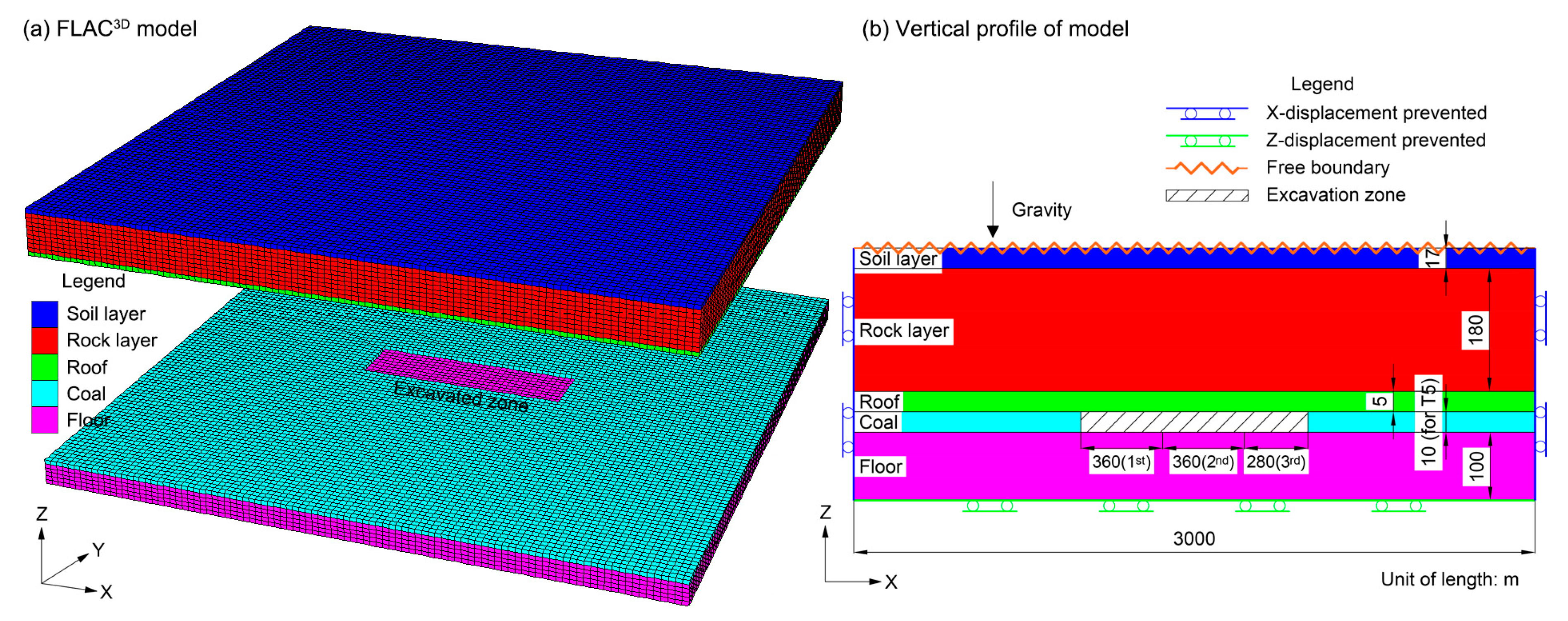
For each model, the horizontal displacement at the four vertical boundaries is restricted. More specifically, as shown in
Figure 2, the x-direction displacement in right and left side planes is fixed, as well as the y-direction displacement in front and back side planes. The vertical displacement at the bottom is also restricted, whereas the top surface is free.
All internal displacements of the model are caused by gravity without any additional external forces. That is, the initial stress of the model only depends on the weight and property of the layers.
The model after excavation for Test 5 is shown in
Figure 2 as an example. To better illustrate the ore body layer, for the 3D model in
Figure 2a, the overlying strata are uniformly raised by 1000 m (just for display). The plane size of this model is 3000 × 3000 m, which is fixed for all 25 models. The coal thickness is 10 m for this test (from
Table 2), while the thicknesses of the other layers are shown in
Table 3. This model (before excavation) has a total of 183,618 nodes and 170,000 blocks.
After the initial model balance, the displacements and velocities are reset to zero. The simulative excavation in the coal layer is then implemented based on the orthogonal experiment scheme given in
Table 2. The excavation zone for Test 5 is 300 × 1000 m. It is noted that to consider the mining speed, the excavation zone is extracted several times to match the designed size. Each time, the excavated length in the strike direction is set as the designed mining speed times 30 days (e.g., 12 m/day × 30 day for Test 5). As illustrated in
Figure 2b, to shape the final excavation zone (1000 m in the x-direction), we mined 3 times in the coal layer: 360, 360 and 280 m for the first, second and third time, respectively.
3.4. Simulation of Ground Subsidence Displacements and Deformations
(1) Computation of Ground Displacements (Vertical Subsidence and Horizontal Displacement)
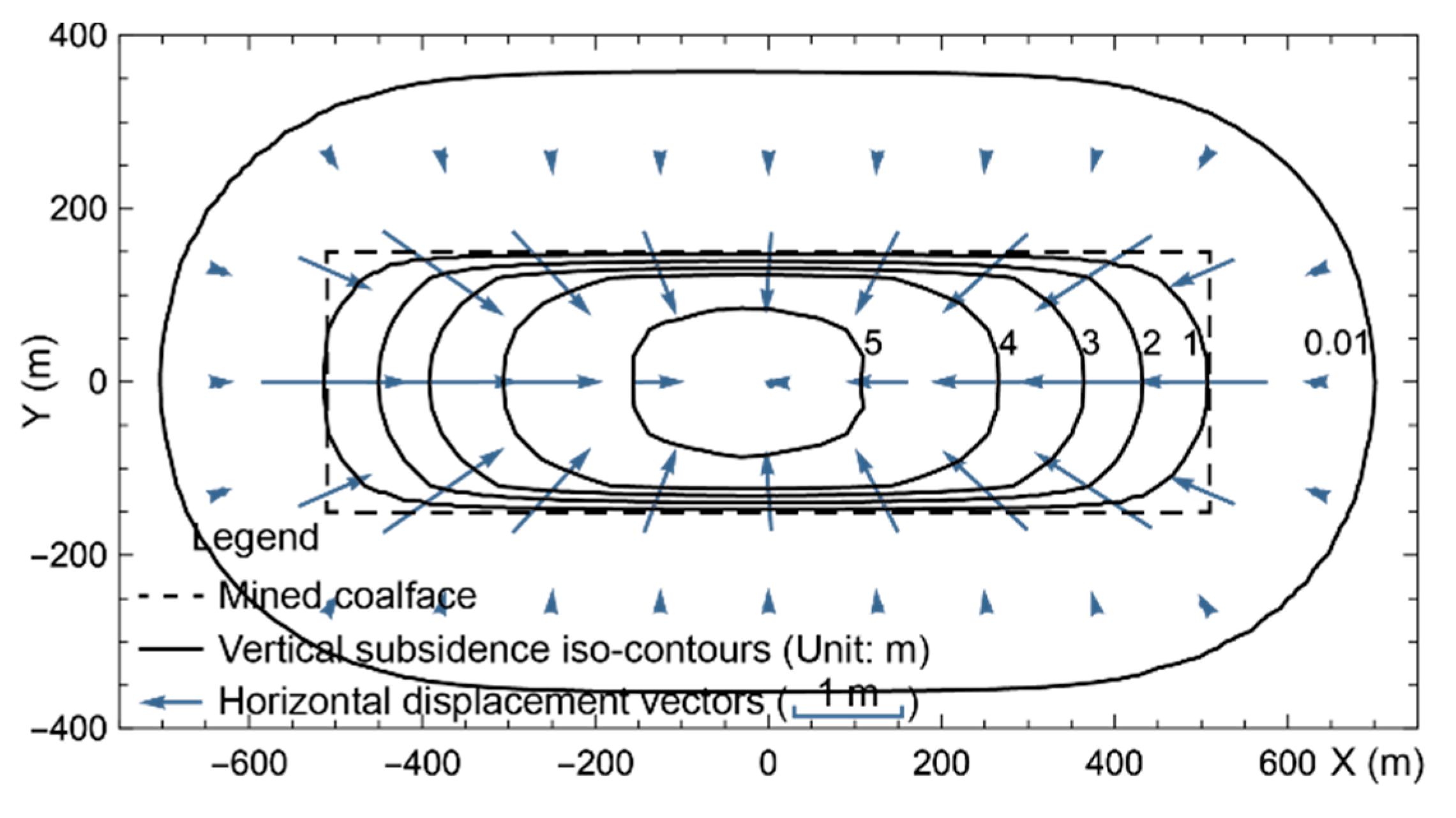
The vertical subsidence and horizontal displacement at all model nodes are extracted after the excavations. The ground values (top surface of the model) are managed with the software Mathematica in table form. As shown in
Figure 3, the vertical subsidence is plotted as iso-contours and the horizontal displacement is plotted as vectors. The horizontal displacement could also be plotted as iso-contours in the strike and dip directions of the coalface, which would require two separate figures.
The criticality of the excavation is related to the size of the coalface, including the lengths in the dip and strike directions. Based on the experiment design, the minimum length in the strike direction was 600 m to ensure the excavation was always super-critical along this direction with a mining depth of 200 m. The simulated vertical subsidence data show that when the length in the dip direction is 250, 300, 350, 400 and 450 m, the vertical subsidence coefficients are 0.47, 0.53, 0.56, 0.56 and 0.56, respectively. Therefore, when the length in dip direction reaches 350 m, the excavation is considered to be critical in this direction, giving a vertical subsidence coefficient of 0.56.
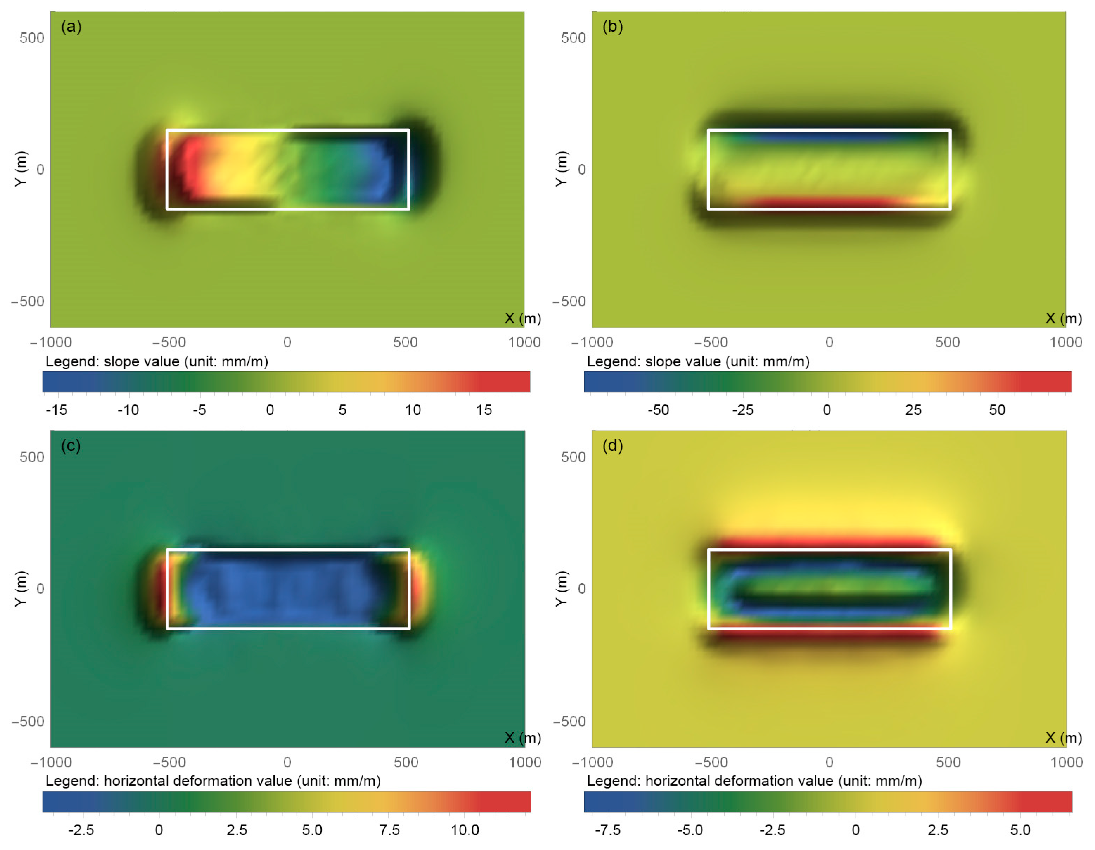
(2) Computation of Ground Deformations (Slope, Curvature and Horizontal Deformation)
Ground damage is not only determined from the ground displacements, which are the direct result of the simulations, but also by the ground deformations, including the slope, curvature and horizontal deformation. These deformation factors can be derived from the ground displacements.
The slope
i(x) is the first derivative of the vertical subsidence
W(x):
The curvature
K(x) is the first derivative of the slope
i(x) (second derivative of the vertical subsidence
W(x)):
The horizontal deformation
ε(x) is the first derivative of the horizontal displacement
U(x):
These three deformation factors can be represented as two orthogonal components, normally along the strike and dip directions of the coalface. Taking Test 5 as an example, the slope and horizontal deformation are plotted in
Figure 4.
(3) Verification of Simulated Results
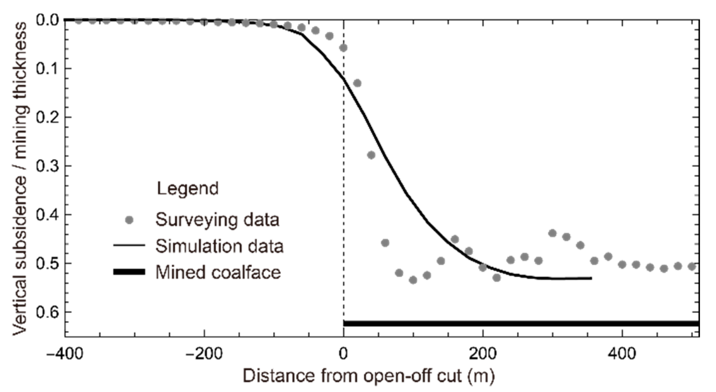
The vertical subsidence of the ground surface was measured 11 times during the excavation of the prototype coalface; the 11th dataset (obtained after the subsidence was stopped) was used to verify the corrections in the numerical simulation results. A simulation test with the coalface parameters close to the prototype is employed for the comparisons. Test 3 was appropriate as its length in the dip direction, thickness and mining speed were 300 m, 6 m and 14 m/day. However, the length in the strike direction of the coalface of Test 3 was 600 m, which was much shorter than that of the prototype (3529 m). Such a length ensured that the excavation reached critical and the comparison of the surveying and simulation data was only at the half-side close to the open-off cut. Therefore, differences in the strike lengths are acceptable. For a better comparison, the vertical subsidences of the surveying and simulation data were divided by their mining thicknesses (4.81 and 6 m) and then plotted (
Figure 5).
The numerical simulation is concerned about some specific geological and mining conditions, so the other conditions were simplified, which makes the simulation model similar, but not identical to the prototype. As a result, the simulated subsidence data did not entirely fit the surveying data [
14,
15,
48,
49]. Moreover, field measurement precision was dependent on many issues, such as the stability of the measuring points, the quality of the measuring instruments and the observation conditions. Therefore, noise was always a part of field surveying data. In contrast, simulated subsidence results usually appear as a smooth line (or curved surface), as they are produced by indoor computation.
Figure 5 shows that the surveying and simulation data fit well together, especially in the aspects of the trend, border and extreme value. The vertical subsidence coefficients, horizontal displacement coefficients and the boundary angles (boundary is where the vertical subsidence is 10 mm) in the strike direction as obtained from field surveying and numerical simulations are all close to each other (
Table 4). The above comparison illustrates the credibility of the simulations.
4. Key Parameters of The Coalface on Ground Damage
The computed subsidence factors—including the displacements (vertical subsidence and horizontal displacement) and deformations (slope, curvature and horizontal deformation)—are used to assess the damage extent of all ground points. Then, the DEI was defined to represent the global damage of the subsidence range and used to analyze the key parameters of the coalface with respect to the ground damage.
4.1. Grading of Mining-Induced Ground Damage
When assessing ground damage, it is necessary to consider the objects on the ground surface. Different objects are sensitive to different subsidence factors; their thresholds for damage are distinct. In fact, the damage assessment of the ground is aimed at ground objects and not the ground itself. Thus, the objects should be identified before the assessment.
Two kinds of objects are selected for this study: buildings and timberland. Both objects are typical in our study area and have ready-made and distinct assessment criteria. It is noted that this paper is not concerned with rulemaking, but instead uses existing industry standards.
Table 5 and
Table 6 show the damage assessment criteria of buildings and timberland as derived from “The Regulations of Coal Mining and Pillar Design for Protecting Buildings, Water Bodies, Railways, Main Mineshafts and Tunnels” [
33] and “Regulation on Compiling Land Reclamation Plan—Part 3: Underground Coalmine” [
50], respectively. From these two assessment criteria, it is found that the building damage is primarily sensitive to the subsidence factors of deformations and the timberland damage is related to both subsidence displacements and deformations.
When assessing ground damage, all the involved subsidence factors at the top nodes of a simulation model should be compared to the criteria in either
Table 5 or
Table 6. As long as one subsidence factor reaches the lowest value of a damage grade, the damage extent of the ground at and around the node is assessed as being at that damage grade. The damage area at each damage grade can be computed at the same time.
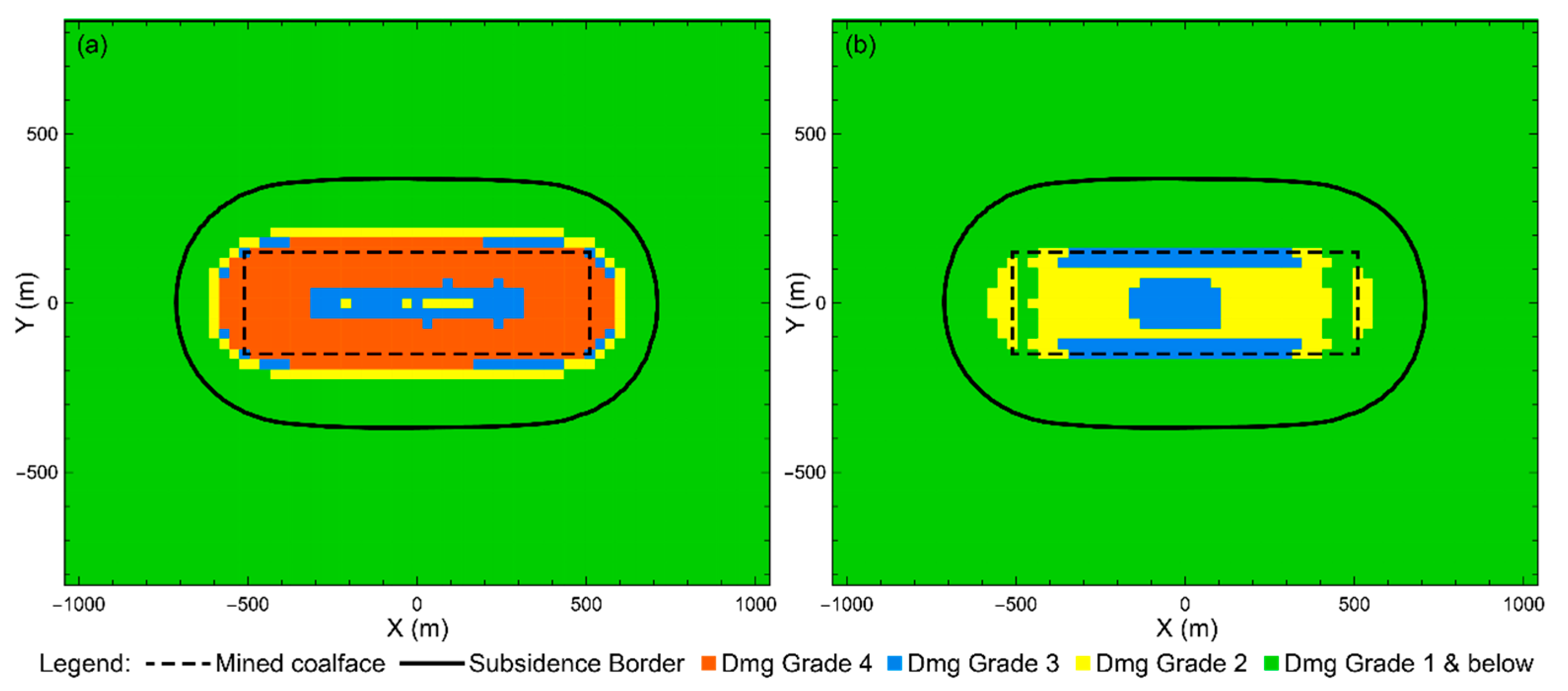
Taking Test 5 as an example, the results of the damage grade assessment regarding buildings and timberland are shown in
Figure 6.
From
Figure 6a (distribution of the building damage grade), the highest damage grade (grade 4) occurs along the edges of the coalface, and the damage grade appears lower (grades 3 and 2) inside the coalface. This is because only the subsidence deformations (slope, curvature and horizontal deformation) are considered in the building damage assessment criteria. From studies of subsidence rules [
11,
48,
51] and the illustration in
Figure 4, the maximum values of the subsidence deformations normally appear along the edges of the mined coalface.
From
Figure 6b (distribution of the timberland damage grade), the highest damage grade (grade 3) appears both around the center and along the edges of the coalface. This is because both the subsidence deformations (slope and horizontal deformation) and the vertical subsidence are considered in the assessment criteria of timberland; the maximum vertical subsidence appears around the coalface center, while the maximum deformations appear along the coalface edges.
The above analyses are based on the simulation results obtained for Test 5; for the other tests, the absolute damage grades could be different, but the distribution rules for the damage grades are the same.
According to the subsidence rules, normally, the permanent and dynamic subsidence damages happen along the coalface edges and inside the coalface, respectively. They are both concerned in mining damage studies. In the Shendong coalfield, the dynamic damage inside the coalface appears “self-repairing” characteristic, which can be mainly attributed to the following two reasons:
- (1)
During the excavation process, the ground surface upon and inside the coalface is first influenced by tensile deformation and then influenced by compressive deformation. The cumulative influence of these two deformations makes the ground damage extent first increases and then decreases.
- (2)
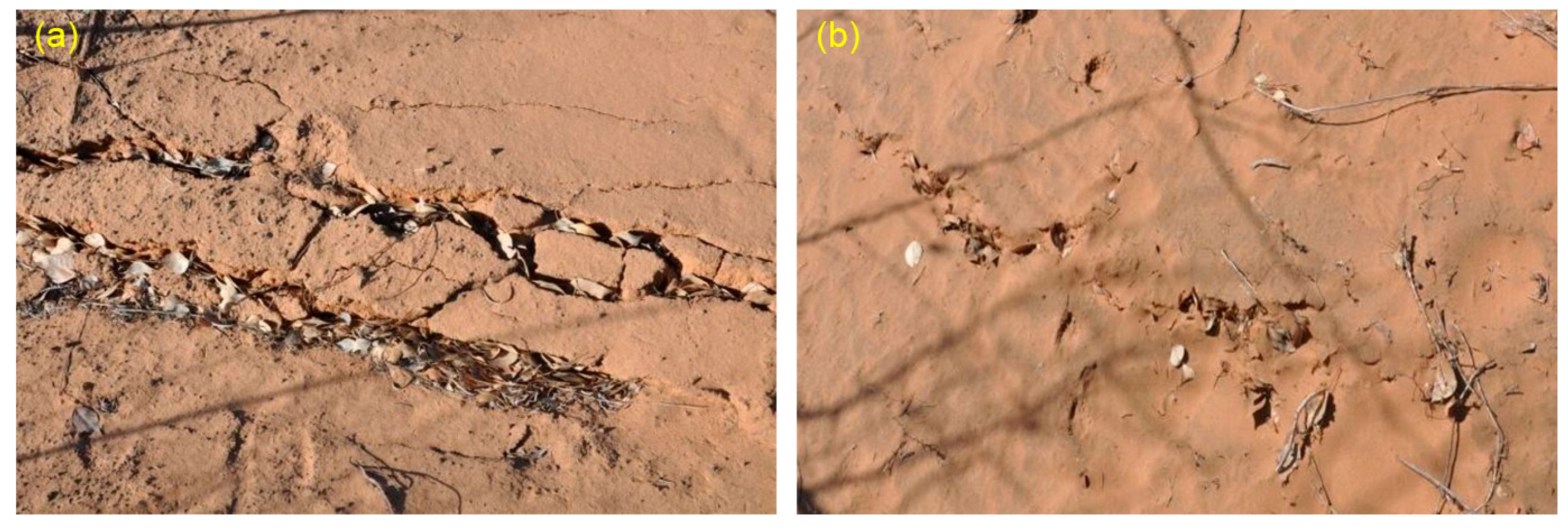
The topsoil of our study area is aeolian sandy soil, which has properties as easy weathering and high fluidity. According to Refs. [
4,
27,
52], such topsoil is advantageous to the restoration of the mining-damaged environment. For example, as illustrated in
Figure 7, the ground fissures are self-restored without human intervention within one month after their first appearance.
As this study uses existing industry standards, the distribution and extent of the ground damage are very dependent on the involved assessment indicators. If the vertical subsidence is used, the center of the subsided basin is with higher damage grade; otherwise, the lower grade appears around the center.
4.2. Ground Global Damage Extent Index (DEI)
The distribution figures of the damage grade can be used to gain intuition and judge the extent of ground damage as induced by the subsidence, but in a more subjective way. The intent is to find a more quantitative index to represent the extent of global damage of the entire subsidence range. More specifically, the goal is to use a single index to represent the damage extent caused from a given simulation test and then to study the influence of the coalface parameters on this index.
Both the damage areas and grades are considered to affect the index—DEI, which is defined as the ratio of the summation of all the products of the damage area and the relevant damage grade to the total subsidence area:
where
S10 is the area of the entire subsidence range (where the vertical subsidence >10 mm),
grd is the damage grade valued from 1 to
n (
n = 3 and 4 for timberland and buildings, respectively) and
Sgrd is the area of the ground surface at the damage grade
grd.
A higher DEI indicates a more significant extent of global ground damage. Because the amount of grade, the involved subsidence factors and the threshold values of the subsidence factors at each grade are different for different criteria (e.g.,
Table 5 vs.
Table 6), the DEI is calculated separately for buildings and timberland in each simulation test; the results are given in
Table 7. It should be noted that this index is not used to assess the damage grade of a specific point; the indexes obtained from different assessing criteria are not comparable.
4.3. Key Parameters of Coalface on Global Ground Damage
This study uses the ANOVA method to determine which of the four simulative parameters of the coalface affect the ground damage, i.e., to find out the so-called key parameters. This statistics method is used to determine the significances of factors on the research results (the DEI in this case) by analyzing the contributions of variations from different sources to the total variation.
Using the ANOVA functionality of Mathematica and taking the four coalface parameters in
Table 2 and the DEI results in
Table 7 from all 25 tests into account, the variance analysis tables are computed and given as
Table 8 and
Table 9 with respect to the DEI for building and timberland damage assessments, respectively.
In ANOVA, the zero hypothesis H0 is that the factors (Factors A, B, C and D) do not have influence on the DEI; the alternative hypothesis Ha is that one or more factors have influence on the DEI; and the significance level α is 0.01.
Taking the P-Value in
Table 8 and
Table 9 that are less than 0.01 as reliable, the key parameters of the coalface that affect the ground damage (the DEI) are not the same for buildings and timberland.
As illustrated in
Table 8, the factor A (length in the dip direction) and factor C (thickness) significantly influence the DEI, i.e., they are the key parameters of the coalface considering buildings on the ground. The relationship from fitting these two factors (the 2nd and 4th columns in
Table 2) and the simulated DEI (the 3rd column in
Table 7) using the least square method in Mathematica can be described by the following equation:
where
DEIbld is the DEI obtained from the building damage assessment,
A is the length of the coalface in the dip direction (factor A) and
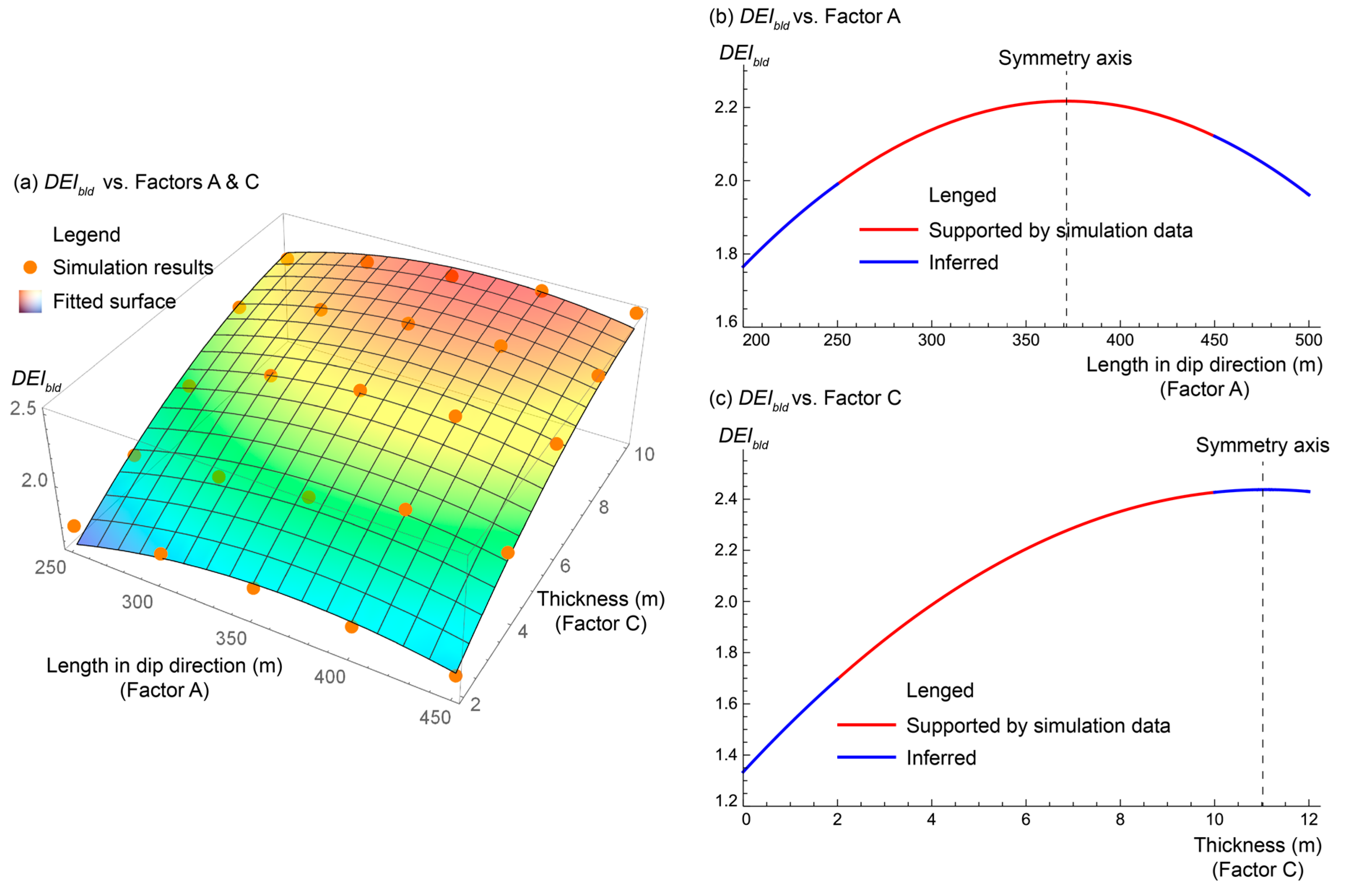
C is the thickness of the coalface (factor C). The DEI with respect to building as obtained by the simulations and the fitting equation are shown in
Figure 8a. The parts
and
in Equation (11) are plotted in
Figure 8b,c, respectively, for better understanding.
As illustrated in
Table 9, the factor C (thickness) significantly influences the index DEI, i.e., it is the key parameter of the coalface considering timberland on the ground. The relationship by fitting this factor (4th column in
Table 2) and the simulated DEI (4th column in
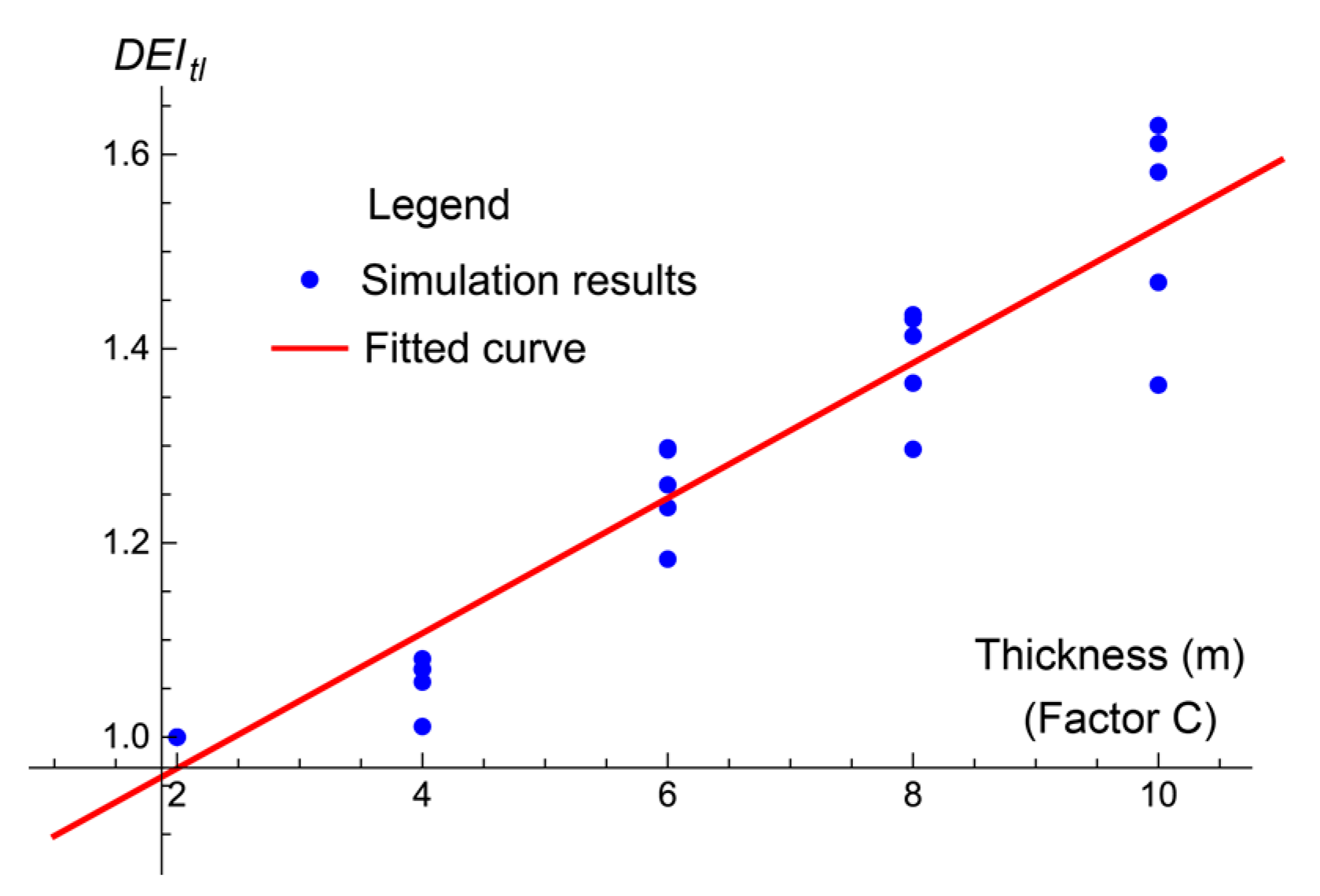
Table 7) using the least square method in Mathematica can be described by the following equation:
where
DEItl is the DEI obtained from the timberland damage assessment and
C is the thickness of the coalface (factor C). The DEI with respect to timberland as obtained by the simulations and the fitted equation are shown in
Figure 9.
4.4. Analyses and Discussions
The damage grade distribution shown in
Figure 6 and the results of the variance analysis in
Table 8,
Table 9 and
Figure 8,
Figure 9 based on both the building and timberland damage assessments indicate that:
(1) For different ground objects, the key parameters of the coalface on the ground damage are distinct.
Many studies [
4,
7,
8,
17,
19,
21,
27,
28,
29,
41,
53] have discussed the differences of mining-subsidence influences on different surface objects. The sensitive subsidence factors, damage grading method and the damage mechanisms are interested topics.
This paper is more like a reverse study, after the assessment of the ground damage, the assessed results are used to back analysis of the so-called key parameters of the coalface. For buildings, the length in the dip direction and the thickness of the coalface are the key parameters; for timberland, only the thickness of the coalface is the key parameter.
(2) When assessing the building damage, three ground subsidence deformations (slope, curvature and horizontal deformation) are considered. Higher grade damage occurs along the coalface edges.
The influence of the coalface length in the dip direction (factor A) on the extent of global ground damage (the DEI) can be represented by the
in Equation (11), which appears as a quadratic curve, as shown in
Figure 8b. As the coalface length in the dip direction increases, the DEI increases first before reaching its extreme value at a dip length of 371.17 m and then decreases. From the simulation experiments, when the length in the dip direction reaches 350 m, the excavation zone is considered to be critical. Therefore, the above rule can be summarized as follows. When the excavation is sub-critical, longer coalface lengths in the dip direction aggravate the global ground damage (increased DEI) due to the increased subsidence deformation. After the excavation becomes critical, longer coalface lengths in the dip direction increase the subsidence range, but the subsidence deformation does not increase (according to general subsidence theories [
54]). Therefore, the area with low damage grade(s) enlarges around the center of the subsidence range, which reduces the global damage extent (decreased DEI). In the Shendong coalfield, the mining and geological conditions are simple and favorable to design successive coalfaces in the dip direction to ensure the excavation inevitably becomes critical (or super-critical) after several coalfaces have been mined. The increased coalface length in the dip direction can accelerate the process of sub-critical to super-critical excavation, i.e., it is advantageous for ground protection. The simple conditions in the Shendong coalfield may cause the length in the dip direction of one super-large coalface to reach (or be close to) the demand value of critical excavation, which causes the appearance of an extreme DEI. This case should be avoided, so it is better not to set the dip length of the first mining coalface at around 350 m.
The influence of the coalface thickness (factor C) on the extent of global ground damage (the DEI) can be represented as the
in Equation (11), which is quadratic and similar to the length in the dip direction, as shown in
Figure 8c. The experimental range of the thickness is 2–10 m and is located at the left side of the curve where it monotonically increases. Therefore, it is determined that as the thickness of the coalface increases, the global ground damage aggravates (increased DEI) due to the increased subsidence deformations. However, when the thickness of the coalface is close to a certain value (11.09 m in this case, which is the peak of the curve), the rate of increase of the DEI slows. As the experimental thickness ranges from 2 to 10 m, the right side of the curve (where the thickness >11.09 m) is not supported by the experimental data and cannot be considered as the influencing characteristics on the DEI. Fortunately, the thickness of coalface in our studied coal mine is not such large, which is also uncommon in other mines.
(3) In the assessment on timberland damage, vertical subsidence and two ground subsidence deformations (slope and horizontal deformation) are considered. Higher grade damage occurs along the edges and around the center of the coalface.
From Equation (12), the mining thickness and the global ground damage (the DEI) are linearly related. As the coalface thickness increases, the global ground damage aggravates (increased DEI). Comparing the assessment criteria of the buildings and timberland (
Table 5 and
Table 6), it is found that the timberland can bear higher slopes and horizontal deformations than the buildings and also takes vertical subsidence into account. According to the normal subsidence rules, when the excavation zone is horizontal (or with a gentle slope) and becomes critical, the mining thickness and the maximum vertical subsidence have a linear relationship. Therefore, it is speculated that in the damage assessment of timberland, although the slope and horizontal deformation are considered in the assessment criteria, the vertical subsidence is the most sensitive factor.
(4) Although the relationship between the mining speed and the extent of ground damage is not found in this study, it cannot be arbitrarily concluded that they are not related. This gap may be due to the research method and/or the assessment criteria used in this study, which are not sensitive to the mining speed.
(5) The mining damage studies are gaining more attention nowadays. The existing industry criteria [
33,
50] and some research achievements [
7,
28,
53] are well applied in the damage assessment. These assessment methods intend to evaluate both the damage distribution and extent of the ground as precise as possible, thereby multi assessment indexes are employed. However, in this study, the damage extent is an intermediary to decide the key parameters of the coalface, it must be quantitative and simple. So, the damage index DEI first introduced herein is quite different from the other studies. It is employed to represent the global damage extent of the entire subsidence-influenced area.
5. Conclusions
An orthogonal design method was introduced into the numerical simulation experiments to study the ground damage caused by the super-large coalface in the Shendong coalfield.
An index DEI was introduced to assess the extent of global ground damage of an undermined model. It was defined as the ratio of the summation of all the products of the damage area and its relevant damage grade to the total subsidence area (where vertical subsidence >10 mm). A greater DEI signified more intense global damage occurs at the ground surface. The ANOVA method was then employed to determine the key parameters of the coalface that affect the DEI. There are two main achievements in this study.
(1) The key parameter(s) of a coalface on the ground damage
For different ground objects, the key parameters of the coalface and their influences on the DEI were distinct and described as follows.
The DEI for buildings was sensitive to the dip length and thickness of the coalface. As the dip length increased, the DEI (extent of global ground damage) increased when the excavation was sub-critical but decreased after the excavation became critical. As the thickness increased, the DEI increased, but its increase rate slowed and fell to zero (the DEI reached its extreme value) when the thickness reached approximately 11 m.
The DEI for timberland was sensitive to the thickness of the coalface. The relationship between the thickness and the DEI was positive and linear.
The above achievements were obtained from the conditions of our study area. Although the absolute values of the results may have limitations, the rules and trends of the ground damage caused by the excavation of super-large coalfaces may be used as a reference elsewhere.
(2) The Index DEI
The DEI is a new indicator in the research of mining subsidence damage. Compared with the existing damage assessment indexes aiming at assessing the damage extent of the ground points, this index is simpler, more macroscopic and is suitable to be applied in further analyses, e.g., the parameter optimization of the coalface in this paper. It also can be adopted in other studies concerning the global environment of the mining area.


