Abstract
Patients with neurological or orthopedic lesions require assistance during therapies with repetitive movements. NURSE (cassiNo-qUeretaro uppeR-limb aSsistive dEvice) is an arm movement aid device for both right- and left-upper limb. The device has a big workspace to conduct physical therapy or training on individuals including kids and elderly individuals, of any age and size. This paper describes the mechanism design of NURSE and presents a numerical procedure for testing the mechanism feasibility that includes a kinematic, dynamic, and FEM (Finite Element Method) analysis. The kinematic demonstrated that a big workspace is available in the device to reproduce therapeutic movements. The dynamic analysis shows that commercial motors for low power consumption can achieve the needed displacement, acceleration, speed, and torque. Finite Element Method showed that the mechanism can afford the upper limb weight with light-bars for a tiny design. This work has led to the construction of a NURSE prototype with a light structure of 2.6 kg fitting into a box of 35 × 45 × 30 cm. The latter facilitates portability as well as rehabilitation at home with a proper follow-up. The prototype presented a repeatability of ±1.3 cm that has been considered satisfactory for a device having components manufactured with 3D rapid prototyping technology.
1. Introduction
Life expectancy continues to increase, accompanied by motor disabilities in the elderly population, and exercising is an important way to prevent their depletion [1,2]. Particularly, neurological and orthopedic lesions can affect upper limb mobility [3]. Therefore, the restoration of the ordinary function of the upper limb is essential through therapy exercises [4].
The aim of the rehabilitation robotics is to assist and support medical activity during a therapy as well as to accelerate the patient recovery process and to maintain the human health. An early recovery of sick or injured people is important for their integration into daily life. Therefore, since patients require assistance during the execution of repetitive movements and robotic system advantage this process [5,6], a lot of devices have been developed to support the upper limb exercises. For example, in [7] a support system is projected to allow movement on vertical elbow flexion and shoulder/elbow horizontal flexion and extension. However, the device only conducts fundamental motions, but it does not carry out other paths. For the upper limb exercises another mobile device is suggested in [8]. The device is comprised of an H-shaped cable-driven machine, two motors, and a hand grip. The system has four guides that restrict the motion of the end-effector in a vertical line, a horizontal line and two 45-degree diagonal rows. The path movements include the shoulder and the elbow. Nevertheless, since mechanism paths are restricted by four guides that limit the end effector along right lines, it is impossible for the mechanism to do other exercises. Moreover, without the flexibility required to adapt the practice/therapy to individual needs all patients should carry out the same trajectories. In addition, the patient response can modify the tension of the wires because the unit has a cable-driven system. Another portable device is presented in [9]. The device is composed by a base plate, hydraulic damper, restrictor arm, actuator arm, elbow cup, and hand grip. The device can assist the internal and external rotations of both right and left shoulders. Using the device, the arm should be attached to the device so that the elbow is located in a fixed position and the hand should grasp a handle. The device can get a horizontal or inclined position. However, the device can only perform one exercise and it can only assist the shoulder joint but not the elbow.
Although existing systems have a large workspace, they are very difficult to carry, build, and wear. In [10], the authors proposed a planar three DoF (degrees of freedom) exoskeleton robot that assists horizontal motion for shoulder, elbow, and wrist. The exoskeleton is controlled by a cable-drive system. The user’s arm is located on the top of the robot structure. The distances between the axes can be adjusted for each subject. Nevertheless, since the apparatus requires a voluminous framework structure, transportation and construction is hard. The biomedical robot is furthermore adjustable only for the right upper limb, and the design has problems in aligning the mechanism joints with the upper limb joints. An exoskeleton powered by a cable is presented in [11]. However, the exoskeleton is hard to dress because its exoskeleton structure surrounds the upper limb. However, it offers additional exercises regarding the exoskeleton in [10]. Another example is presented in [12], where a biomedical device is proposed for a robotized rehabilitation for a human upper limb. The biomedical device is an exoskeleton type that is principally composed by two rigid rods that are associable with the forearm and the upper arm by joints with four degrees of freedom. This device has a bulky frame structure that is difficult to transport. In addition, the exoskeleton structure is hard to wear.
Commercial devices are currently also available for upper limb exercises. In [13,14], a commercial exoskeleton with ergonomically actuated shoulder is presented. However, it has voluminous bars and frame. In addition, it is hard to wear and it is expensive. In [15,16], a popular device that consists of a visual interface and a robotic arm to guide the patient’s arm along desired paths is presented. A five-bar mechanism is used to drive the robotic arm by two motors, which execute horizontal motions. In addition, a modular end-effector assists the wrist joint movements. However, the device is very complex and difficult to operate and requires well-trained staff to guarantee safe operations. Moreover, the device is expensive, heavyweight and it has a very tiny workspace for the exercises. In [17], a sophisticated commercial device based on the exoskeleton in [13,14] as described in [18] is presented. The exoskeleton has six degrees of freedom to perform 3D motions and a graphical interface for virtual interaction. However, this exoskeleton presents the similar disadvantages of the exoskeleton in [13,14]—a bulky frame, difficulty to wear, and costly. ReoGo is a commercial and portable robotic arm [19] that has a mechanism similar to a joystick. ReoGo performs two-or three-dimensional movements and it also has an interface for virtual interaction. The disadvantage of ReoGo is its small workspace. NeReBot is another device for arm therapy [20]. NeRebot is a cable-suspended device of three DoF with three cables whose end-effector moves inside a spatial working space. The robot cables are driven by three electric motors. The cables are connected to the patient’s upper limb by using an arm support whose end-effector moves inside a spatial working space. The structure to support the cables can be adjusted manually. The NeReBot performs repetitive passive movements of the upper limb and it can be used by having the user in a chair or a bed. However, NeRebot is heavy and presents some disadvantages [21]—it is bulky and some horizontal movements of the upper limb cannot be performed properly.
Rehabilitation centers often use the skateboard instrument to assist the training exercises for the upper limb [22]. The skateboard consists of a wheel board that enables horizontal movement. Using the skateboard, a therapist guides the movement of the patient’s arm and the patient does the movements by himself. The skateboard is an affordable system, but usually does not have a regulated movement. In [23], a portable device for arm therapy similar to a skateboard is proposed. The mechanism consists of a mobile platform with three spherical wheels. The platform is attached to the forearm and it can perform movements in a horizontal plane. The device has an optical tracking system that is composed of two optical mouse sensors. However, since the platform is not attached to a fixed frame the patient’s reaction can easily alter the reading of the mechanism positions.
As described in the above paragraphs, the existing devices has several issues. Table 1 shows a summary of advantageous and disadvantageous features of the referenced devices. Regarding exoskeletons and semi-exoskeletons in [10,11,12,13,14,17,18], despite offering a large workspace they present bulky frames that hinder its transport and its building. Most of them use of bulky links that must be moved by the motors requiring greater torque than if light links. In addition, the exoskeletons are difficult to wear since they should surround the patient’s arm as if it were a sleeve. Moreover, the joint axes of exoskeletons should be aligned with the anatomical axes of the human arm and it is hard to get it considering that the human arm sizes are different for each subject. In addition, it should be mechanically reconfigured for right and left human arm. On the other hand, the portable devices referred in [7,8,9,19] are portable devices with light frames which could eventually be used as home devices with the proper supervision of a specialist. However, they have predefined paths that cannot be modified due their mechanical shapes, thus the number of exercises or trajectories that they can offer is very limited. Although manipulator devices in [15,16] can perform several paths, they work with a limited workspace considering the human arm workspace on the horizontal plane and the mechanism sizes. In [23], the device is a controlled skateboard design that can be moved as the patient requires. However, since it is not attached to a fixed frame the patient’s reaction can easily alter the reading of the mechanism positions. Moreover, the device in [23] is a patented idea and practical designs or experiences are not available to consider its feasibility. On the other hand, the proposed solution in this work has aimed to design a mechanism that merges together most of the advantageous features of existing mechanisms but avoids the disadvantageous features that each one of them presents. The proposed device has been designed to offer a large workspace without bulky frames to guide both the left and right upper limbs without the need to be mechanically reconfigured, to follow desired paths by programming the device avoiding that the mechanical structure predetermine paths that cannot be modified by programming, to offer a light structure for portability and therefore facilitate rehabilitation at home with the proper tele-supervision of a specialist, to provide a design with light links reducing the load that the motors of the mechanism must move reducing the required torque and consequently the power consumption that is directly proportional, and to offer the possibility of programming different paths customized for people of different sizes and needs such as children and the elderly people without the need of mechanical reconfigurations or the need of a kid’s version design.

Table 1.
Summary of advantageous features (A.F.) and disadvantageous features (D.F.) of the referenced devices.
2. Mechanism Task
Medical experts at the Center of Rehabilitation of Queretaro in Mexico (CRIQ) reported that multiple training sessions during arm treatment are usually performed on a table where the patient’s arm is supported by a skateboard [22,24]. The exercises consist of performing horizontal movements on a suitable table while the skateboard supports the patient’s arm and the therapist assists the arm motion. However, existing devices that assist the arm motion on horizontal plane, as reported in the introduction section, have several issues that should be solved. Therefore, an innovative mechanism has been required to guide the human arm motion on a horizontal plane with advantages over the existing devices. The mechanism task is to guide the movements of the human arm along predefined paths on a horizontal plane.
A manipulator has been considered as an appropriate mechanism type to assist the arm exercises on horizontal plane since the patient’s hand could be assisted by the mechanism end-effector similar to when the therapist does it. So that, the mechanism end-effector should perform movements along X and Y coordinates and it should reach most of the workspace essential to perform upper limb exercises on a horizontal plane. The space needed for horizontal arm training has been estimated using mean anthropometric parameters for the upper limb lengths [25,26] (See Figure 1). The average length of the arm, from the shoulder to the middle of the hand, has been calculated as 667.5 mm. Consequently, the space required for horizontal arm training has a maximum height of 667.5 mm and a maximum width of 1335.0 mm. On the other hand, multiple exercises can be achieved by the upper limb on a horizontal plane as described in [22,24]. However, in order to test the proposed device, one exercise has been chosen. To carry out the exercise, the number eight path should be traced by the manipulator end-effector. The coordinated motions to carry out the number eight path is complex enough to test the proposed device [24]. X and Y references versus time to perform the exercise has been obtained from previous experiments whose results have been reported in [24,27] where arm exercises on horizontal plane were designed using several samples of healthy individuals and processing the references by regression analysis. Figure 2 shows X and Y cartesian coordinates to trace the number eight.
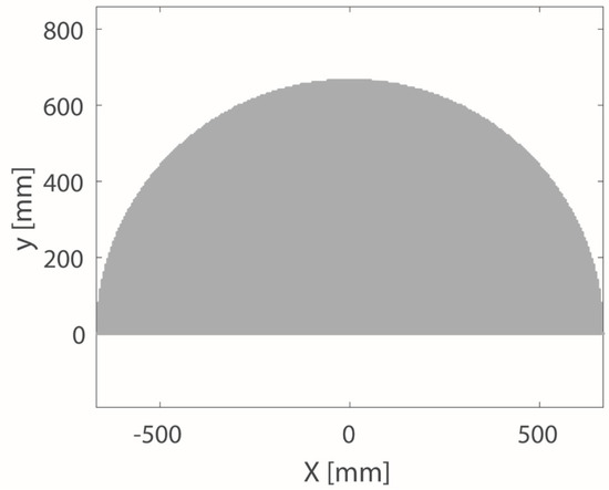
Figure 1.
Workspace of the upper limb on a horizontal plane.
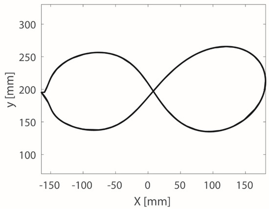
Figure 2.
X and Y cartesian coordinates to trace the number eight.
3. Kinematic Analysis and Design Parameters
To control an end-effector position consisting of cartesian compounds X and Y, two DoFs are needed. On the other hand, a planar mechanism is enough to perform movements on the planar workspace in Figure 1. Therefore, a planar mechanism of two DoFs has been proposed (See Figure 3). The suggested mechanism consists of by a five-bar and a pantograph mechanism. The pantograph was designed to enlarge the five-bar workspace and therefore to use tiny connections. The five-bar mechanism mobile bars are L1, L2, L3, and L4 and the pantograph mobile bars are L6, L7, L8, and L9. The bar L5 is the attachment structure set frame. Point E is the pantograph tracing point which is associated to the five-bar mechanism end-effector. Point F is the amplified tracing point to follow the arm exercise path. M1 and M2 are the active joints that will be actuated by motors and they are related with and angles, respectively. The distance H is defined as H = L1 = L2 = L3 = L4. It is important to notice that variable H is included in the kinematics formulation. The , , and angles are required for the kinematic analysis. The point A, E, and F are always aligned for any position of the pantograph so that a straight line connects the three points. The proposed mechanism has been protected by the patent in [28].
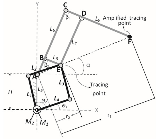
Figure 3.
Proposed mechanism for arm motion assistance.
The rotational movements of M1 and M2 were reduced from 0° to 180° to prevent physical collisions. In addition, in order to obtain the maximum possible workspace using the five-bar mechanism [29,30,31] the bars L1, L2, L3, and L4 have equal lengths so that L1= L2= L3= L4, and the joint M1 is aligned with joint M2. Distance |AC|/|AB| give the amplification scale of the pantograph. The dimensional ratios |BE|=|CD|; |BC|=|ED|; |AB|=|BE|; and |AC|=|CF| define the pantograph structure [32]. The mechanism end-effector should, according with the workspace in Figure 1, cover a maximum height of 720 mm and a maximum width of 1440 mm based on an about 5 cm safety factor. From Figure 3, the angle can be defined as:
where YF and XF are the coordinates of the point F (end-effector positions) with respect to the Cartesian reference frame. YF and XF are known inputs in the inverse kinematics. In Figure 3, the triangle formed by points A, C, and F can be defined by using law of cosines in the form:
On the other hand, by using the Pythagorean theorem, can be defined as:
then, replacing Equation (2) in Equation (1):
So that the angle β1 can be computed from Equation (4) in the form:
where is the angle between links L6 and L9. In a pantograph mechanism is defined as:
In addition, the triangle formed by points A, B, and E can be identify by using law of cosines in the form:
where |AB| is the distance between the point A and the point B. The variable can be isolated from Equation (7) as:
Then, the angle in Equation (8) can be substituted by from Equation (6). The angle is a known variable since it can be calculated using Equation (5). Therefore, Equation (8) can be rewritten as:
Since the angle and the variable can be respectively calculated using Equations (1) and (9), the Cartesian coordinates of the point E with respect to the Cartesian reference frame can be defined for both solutions in the form:
Using and values, the angular positions and of the active joints M1 and M2 can be computed for both solutions as follow:
where:
and:
where:
The inverse kinematics is formulated by Equations (12) and (16). Using the inverse kinematics equations, the mechanism workspace can be determined. However, first the link lengths must be defined so that the end-effector can cover most of the workspace of the human arm motion in Figure 1. Therefore, the limits of the mechanism workspace have been approximated by indicating a maximum height (in X-axis) of 720 mm and a maximum width of 1440 mm (in Y-axis) when a safety factor of approximately 5 cm is considered [24].
According to the limit of movement of M1 and M2 (0° to 180°), and the relationship between the bars (L1 = L2 = L3 = L4), five-bar can reach a maximum distance equivalent to the length of each symmetrical link L1, L2, L3, and L4. Thus, the link lengths of the five-bar should be equal to 720 mm to cover the needed workspace without taking in consideration the pantograph. Therefore, since the pantograph can amplify the workspace of the five-bar, a decreases scale of 1/4 has been implemented to the link lengths of five-bar, obtaining that L1 = L2= L3= L4 = (720 mm/4) = 180 mm.
Consequently, the pantograph needs to increase the five-bar workspace by a factor of 4 to cover the required workspace. Therefore, the amplification scale of the pantograph should be |AC|/|AB| = 4. Since the angles and have been delimited from 0° to 180°, the distances |AB|+|BE| should be equal to 180 mm so that the tracing point E reaches the usable workspace of the five-bar. According to the dimensional ratios of the pantograph, since |AB|=|BE| and |AB|+|BE| = 180mm, then |AB|=|BE| = 180 mm/2 = 90 mm; since |BE|=|CD|, then |CD| = 90 mm; since the amplification scales is defined by |AC|/|AB| = 4, then |AC| = 4 × 90 mm = 360 mm; since |AC|=|CF|, then |CF| = 360 mm; since |BC|=|AC| – |AB|, then |BC| = 360 mm – 90 mm = 270 mm; and since |BC| = |ED|, then |ED|= 270 mm. Subsequently, L6 = 360 mm, L7 = 270 mm, L8 = 90 mm, and L9 = 360 mm.
Since the link sizes were defined, the workspace can be calculated using Equations (12) and (16). Figure 4 shows the mechanism workspace (in black) versus the workspace of the upper limb motion on a horizontal plane (in grey). The circles in Figure 4 indicate the uncovered areas of the workspace of upper limb motion. It is important to notice that the patient should be located in a convenient and comfortable place in front to the end-effector (point F in Figure 3) at the opposite side of the active joints. The uncovered areas of the workspace of the upper limb motion are not necessary to perform the proposed exercise and the exercises reported in [24,27].
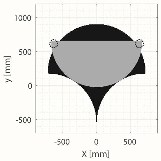
Figure 4.
Workspace of the upper limb motion on a horizontal plane (in grey) and mechanism workspace (in black).
The calculated workspace shown that the proposed mechanism design is able to cover most of the workspace of the human arm on horizontal plane using the proposed link sizes. Consequently, it proved the proposed mechanism need link sizes of maximum 360 mm to cover the required workspace allowing a compact design. In addition, it shown that arm exercises reported in [24,27] can be reproduced within the mechanism workspace since it is large enough.
4. Dynamic Analysis
The feasibility of the suggested linkage mechanism was evaluated by a dynamic analysis using ADAMS solver within SolidWoks software (version 2018, Dassault Systèmes, S.A., Suresnes, Francia) simulating the mechanism performs the exercise path showed in Figure 2 in Section 2. In the simulation setting, a 1060 aluminium alloy has been used for the mechanism links. Table 2 shows the assumed characteristics of the chosen material. The parameters of friction and gravity force are shown in Table 3. The simulation considers an integrator step size of 1.0 × 10⁻⁴, with a maximum value of 1.0 × 10⁻¹ and a minimum value of 1.0 × 10⁻¹¹, 800 frames per seconds and an accuracy of 1.0 × 10⁻⁹. A time of 8 seconds is required to perform the selected exercise path as reported in [24]. Considering the average weight of the upper limb [25,33], a force of 37 N has been applied in the amplified tracing point of the mechanism (Point F in Figure 3 in Section 3) perpendicular to the working plane (Z axis). It is important to note that the amplified tracing point of the mechanism (Point F in Figure 3 in Section 3) must track the desired exercise path showed in Figure 2, Section 2.

Table 2.
Characteristics of 1060 Aluminum alloy.

Table 3.
Body contact parameters for the simulation.
It is important to note that in this dynamic analysis the motors of the mechanism are simulated using the trend of velocities required to perform the trajectory to trace the number 8 as the input parameter, see Figure 5a. The dynamic analysis outcomes are the torque, angular displacement, and angular acceleration required by the simulated motors to perform the prescribed trajectory. Angular displacement, angular acceleration and torque obtained from the dynamic analysis are shown in Figure 5b–d, respectively. Table 4 shows the results for motor 1 obtained from the dynamic analysis as well as the maximum and minimum velocity used as input for motor 1. Table 5 shows the results for motor 2 obtained from the dynamic analysis as well as the maximum and minimum velocity used as input for motor 2. The dynamic simulation outcomes allow to choose the motors for the mechanism construction and to check the efficient operation.
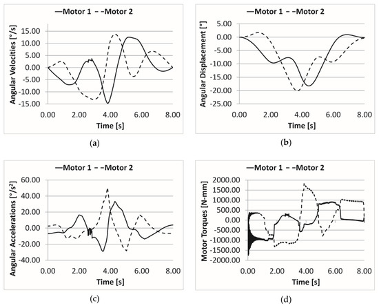
Figure 5.
Input velocities and computed results of the dynamic simulation where the mechanism perform the exercise to trace the number 8: (a) Input velocities; (b) Angular displacements; (c) Angular accelerations; and (d) Motors torques.

Table 4.
Dynamic analysis results for motor 1.

Table 5.
Dynamic analysis results for motor 2.
Referring to Figure 5, and the numerical values reported in Table 4 and Table 5, the angular displacements present a symmetric mechanism performance and the computed accelerations and torques values confirm the possibility to use inexpensive commercial motors. The proposed mechanism has a satisfactory behaviour in achieving the desired objective since it presents a smooth motion and limited torque (referring to plots in Figure 5). Therefore, according to the design and operations requirements, the proposed mechanism can be considered a feasible design to assist the human arm exercises. The mechanism can perform successfully the exercise to trace the number 8 with displacement, acceleration, velocity and torque achievable by commercial motors, referring to Figure 5. In addition, the required torque, shown in Figure 5d, allows a low power consumption to achieve the desired task. Even though the mechanism has been tested via simulation with a specific exercise, other exercises can be also performed by the mechanism within its workspace.
Since the assistive mechanism can perform trajectories of different sizes and shapes within its workspace, the exercises can be customized for people of any anthropometric sizes, including children and elderly people. In addition, the exercises can be customized for physical therapy, for treatments of injuries or diseases, for prevention, or for physical exercising.
5. FEM Analysis
Since the proposed mechanism should assist arm exercises that are normally performed over a work table, proper commercial spherical wheels have been added in the mechanical design in order to give stiffness to the linkage structure and use a work table as support (See Figure 6). Furthermore, an ergonomic interface has been studied and added to the structure to allow the patient to lean the arm and distribute its weight. The mechanism structure has also been attached to a fixed frame with “T” shape for a portable design that can be installed on a table or a flat plate. The fixed frame allows also to use flat motor or other rotational motors.
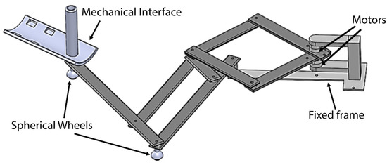
Figure 6.
A CAD design of the proposed mechanism including a mechanical interface and wheels.
A linear static FEM (Finite Element Method) analysis has been performed to test the feasibility of the prototype and to check the response of the proposed structure to the considered applied forces. All the device components have been considered as made of aluminium 1060 alloy with linear elastic isotropic properties as in Table 2. A soil has been considered during the FEM analysis in order to simulate the work table support for mechanism operation. Gravity force has been considered acting along the Z axis. The average weight of the arm has also been assumed as 37 N for the force acting on the mechanism end-effector during the simulation considering the average weight of the upper limb [25,33]. The horizontal forces that can come from the human arm have been considered negligible for the current static analysis. However, they can be considered in a future work using a dynamic FEM analysis. To analyse the model using the proper criteria a mesh is needed. Table 6 shows the mesh information.

Table 6.
Mesh information for FEM (Finite Element Method) analysis.
As Stress Analysis criterion, Von Mises stress function has been used as a measure of all stress components of a general 3-D state of stress. Von Mises stress function σvm, can be expressed by stress components in the form [34]:
where σ1, σ2, and σ3 are the three principal stresses acting on X, Y, and Z-axes of the body. Von Mises stress is a non-negative scalar stress measure that evaluates elasto-plastic properties. This number function represents a stress magnitude, which can be compared against the yield strength of the material in order to determine whether or not failure by yielding is predicted.
Using the maximum Von Mises stress criteria, [34], the condition of safe design can be expressed as:
If the Factor Of Safety (FOS) is 0 we are in a critical condition and if it is <1 the material failed. Displacement along Z, stress and FOS of the proposed mechanism have been obtained from the FEM analysis.
Figure 7a shows the mechanism displacement along Z axis that has a minimum value –1.60 mm and a maximum value of 0.73 mm. Therefore, the reached displacement along Z can be considered negligible.
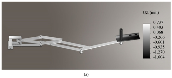
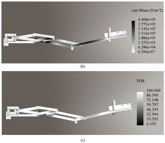
Figure 7.
Computed results from FEM analysis: (a) Compliant displacement; (b) Stress field; and (c) Factor Of Safety (FOS).
Figure 7b shows the computed stress that has a range between 6.39 × 10⁻⁷ N/m2 and 4.45 × 10⁶ N/m2. Therefore, the stress is very far from the yield limit of the material reported in Table 2. The stress results show that the structure is stiff and it can support the applied forces using light bars. Figure 7c shows the computed Factor Of Safety (FOS) check. The FOS values reach a minimum of 6.19 that can be seen in the red zones. Finally, the FOS check shows that no nodes reach failure since its minimum value is 6.19.
6. Lab Prototype
6.1. Mechanism Structure
The workspace, the dynamic analysis and the FEM analysis indicated that the proposed mechanism is a feasible design for upper limb motion assistance on horizontal plane. Therefore, a prototype of the mechanism structure has been built with aluminium alloy. The pieces required for assembling the bars and the motors have been printed by a 3D printer using PLA filament. Figure 8a shows the built prototype and Figure 8b shows a photography of the mechanism prototype while it is easily lifted by a person. Referring to Figure 8b, the mechanism in a retracted position making evident that it is a compact and portable prototype since it weighs only 2.6 kg and it fits into a box of 35 × 45 × 30 cm. As reported in [35] the portability is an important feature for the rehabilitation devices since the rehabilitation at home is necessary for patients that requires long time therapy such as chronic stroke survivor. On the other hand, it is important to note that the exercising is an important way to prevent motor disabilities in elderly people [1,2] as well as portable devices can facility the exercise at home. Figure 8c illustrates the user-mechanism interaction. Both right and left upper limbs can be assisting within the mechanism workspace.
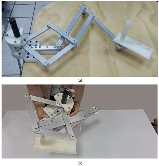
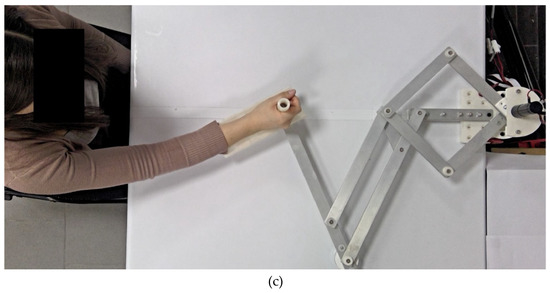
Figure 8.
Prototype of the proposed mechanism: (a) Lab prototype; (b) Mechanism prototype in retracted position while it is easily lifted by a person; and (c) User-mechanism interaction.
Two Maxon motor packages No. 438494 (maxon motor ag, Sachseln, Switzerland) [36] have been chosen to actuate the proposed mechanism in a lab prototype. Each motor package is composed by a motor, a planetary gearhead with a reduction of 71:1 and an encoder for feedback. The resolution of the encoder is 1000 ppr (pulses per revolution) and one turn of the gearhead axis corresponds to 284,000 counts of the encoder. The motor works with a supply of 24 V and a nominal current of 1.5 A. When the chosen motor is coupled to a gearhead, the package reaches a nominal torque of approximately 1657 N mm and a maximum intermittent torque at gear output of 6200 N mm that have been considered enough to carry out experiments with a lab prototype considering that in the dynamic analysis outcomes the torque required by the motors has a maximum peak value of 1821 N mm. In the future, improvements of the prototype and motors with a higher safety factor will be considered. The motor package reaches an angular displacement of 360° that is enough to perform the trajectory to trace the number 8 that requires a maximum displacement of 20.12° and to perform trajectories into the mechanism workspace in Figure 4 that requires a maximum angular displacement of 180°. The chosen motor package reaches the required angular acceleration to perform the required task as well as it has been tested using NMC (Networked Modular Control) Test Utility (Version 1.1, Jeffrey Kerr, LLC, Berkeley, CA, US) that is available for the PIC-SERVO SC control boards in [37]. On the other hand, the motor package reaches a maximum velocity of 818.87 °/s that is higher than the maximum velocity required to perform the trajectory to trace the number 8 that has a maximum value of 14.73 °/s.
6.2. Control Strategy
A control strategy based on a PID control has been developed to control the mechanism. Figure 9 shows a scheme of the designed control strategy where the mechanism has four operation modes: Joint Displacement Mode, Cartesian Displacement Mode, Exercise Mode, and Learning Mode. In the Joint Displacement mode, the mechanism is operated by commanding the desired positions of the active joints as function of the encoder counts so that the trajectory generator sends the signals for motor trajectory and the trajectory is filtered by the PID controller. In the Cartesian displacement mode, the mechanism is operated by commanding the Cartesian positions of the mechanism end-effector. Therefore, the motor positions are calculated using the inverse kinematics of the mechanism and the trajectory generator sends the signals for motor trajectory and the trajectory is then filtered by the PID controller. In the Exercise Mode, the mechanism is operated by commanding the path of the desired exercise. The four arm exercises reported in [27] are available in the Exercise Mode. Once the desired exercise is selected, the motor positions are calculated using the inverse kinematics of the mechanism and the trajectory generator sends the signals for the motor trajectory and the trajectory is then filtered by the PID controller. In the Learning Mode, the motor positions of the mechanism are stored while the user moves the mechanism along a desired path. Then, the trajectory generator sends the signals for the motor trajectory that is filtered by the PID controller.
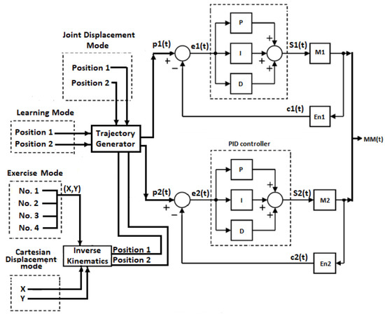
Figure 9.
The designed control strategy scheme.
Referring to Figure 9, the variables p1(t) and p2(t) correspond to the signals for the motor trajectories that are generated by the PIC-SERVO trajectory generator (Jeffrey Kerr, LLC, Berkeley, CA, US) according to the desired positions. The user can specify a desired velocity and acceleration if the default values of velocity and acceleration are not used. The variables (X, Y) correspond to the desired end-effector coordinates; e1(t) and e2(t) correspond to the error of the reached positions; En1 and En2 correspond to the encoders; c1(t) and c2(t) correspond to encoders counts; and M1 and M2 correspond to the motors; S1(t) and S2 (t) correspond to the signals send to the motors and MM (t) is the system output and it corresponds to the mechanism motion that is caused by the motor motion.
Two PIC-SERVO SC Motion Control Boards (Jeffrey Kerr, LLC, Berkeley, CA, US) [38] and an SSA-485 smart serial adapter (Jeffrey Kerr, LLC, Berkeley, CA, US) [39] are the selected main components of the control unit for the mechanism operation. Figure 10 shows the built control unit as connected to the designed mechanism. The PID gains of the PIC-SERVO boards have been tuned using the NMC Test Utility (Version 1.1, Jeffrey Kerr, LLC, Berkeley, CA, US) [37]. The control strategy has been coded in Visual C++ (Version 2005, Microsoft corporation, Redmond, WA, U.S.) together with a user interface. The developed device for arm motion assistance has been named NURSE (cassiNo-qUeretaro uppeR-limb aSsistive dEvice) and it is composed by a planar mechanism of two degrees of freedom, a control unit with PIC-SERVO control boards and a user interface that can be run using a computer, Figure 10.
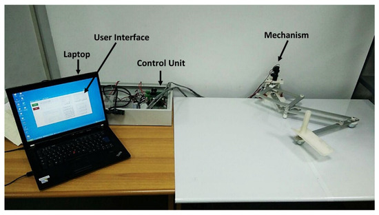
Figure 10.
The built control unit as connected to the designed mechanism.
6.3. Repeatibility Test
An experiment has been carried out in order to estimate the mechanism repeatability according with the Norm ISO 9283 available in [40], where the repeatability is defined as the measure of the ability of a robot to return to a same position and the accuracy is defined as the measure of the ability of a robot to reach a position with the minimum deviation with respect to the programed one. The experiment consists of sending the mechanism end-effector to five critical positions within its workspace during 30 times using a velocity of 396°/s and a load of 0.529 kg. Then, the reached positions are measured in order to apply the repeatability. The repeatability equation for a position [40], is defined as:
where corresponds to the average of the mean square error () of the reached positions and corresponds to the standard deviation of the reached positions. , , and are respectively defined [40] as:
where is the X coordinate of a reached position; is the Y coordinate of a reached position; is the average of the X coordinates of the reached positions, and is the average of the Y coordinates of the reached positions.
In order to determinate the five critical positions [24,40], a rectangle figure is traced within the mechanism workspace covering most of the workspace and the Cartesian coordinates of the four corners and the central point represent the five critical positions (See Figure 11).
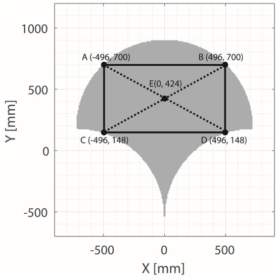
Figure 11.
The considered critical positions (A, B, C, D, and E points) within the mechanism workspace (in grey) with the reference rectangle.
Figure 12 shows the mechanism end-effector reaching the five critical positions. The coordinates of the experimental reached positions have been obtained using red markers on the required positions that are tracked by image processing. Figure 13 shows the reached positions by the mechanism end-effector versus the programmed critical positions A, B, C, D, and E. The repeatability has been successfully computed and it has been obtained that the mechanism has a repeatability of ±1.3 cm. The mechanism repeatability is satisfactory considering that the lab prototype has a low precision manufacture. It is important to note that the encoder error has presented a maximum value of 50 counts (0.063° of motor rotation) which is negligible considering that 284,000 counts are equivalent to 360° of motor rotation.
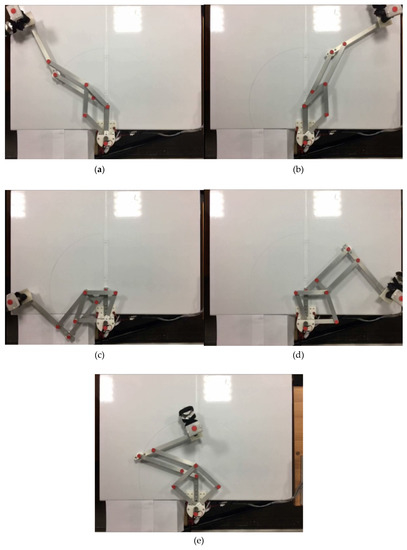
Figure 12.
NURSE (cassiNo-qUeretaro uppeR-limb aSsistive dEvice) end-effector on the two right critical positions in Figure 11: (a) Position A (-496, 700); (b) Position B (496, 700); (c) Position C (-496, 148); (d) Position D (496, 148); and (e) Position E (0, 424).
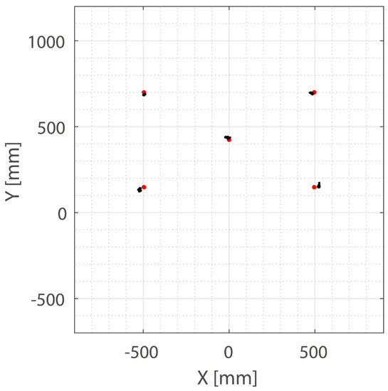
Figure 13.
Positions that have been reached by NURSE device during repeatability test (black points) versus the programed critical positions (red points).
An experimental characterization of NURSE device was carried out by the author using the lab prototype designed in this paper and since it comprised a detailed work it deserved an individual report that can be consulted with free access in [41]. Trajectories, linear accelerations, torque, and power consumption were considered in [41] to check the mechanism behaviour during the reproduction of arm therapy exercises. The experimental results in [41] showed that the proposed mechanism design is capable of reproducing successfully exercises for the upper limb with smooth movements and low power consumption. It is important to note that the article in [41] exposes only experiments with arm therapy exercises, thus the authors have considered important to publish the current paper with the detailed design process to obtain the NURSE device.
7. Conclusions
A feasible portable assistive mechanism has been designed to assist upper limbs exercises on a horizontal plane. A kinematic analysis has shown that a large workspace is available in the device to reproduce therapeutic movements covering most of the work space of the human arm in the horizontal plane. Dynamic analysis outcomes have registered a maximum angular displacement of 20.12°, a maximum angular acceleration of 50.32 °/s2, and a maximum torque of 1821 N mm that are required by the motors to perform the trajectory to trace the number 8. Commercial servomotors can reach the required angular displacement, angular acceleration, and the torque. FEM analysis shows the feasibility of the proposed linkage structure with a suitable response with respect to the considered applied forces presenting a maximum displacement along Z of 1.60 mm that is considered negligible, a maximum stress of 4.45 × 10⁶ N/m2 that is supported by the yield limit of the material, and a minimum FOS value of 6.19 that avoids material failure. NURSE repeatability with a value of ±1.3 cm has been considered satisfactory having components that have been manufactured using 3D rapid prototyping technology. The proposed device offers a large workspace without bulky frames and links unlike existing devices that offer large workspace but bulky frames and links. In addition, NURSE device can guide both the left and the right upper limb without the need to be mechanically reconfigured. Existing portable devices define their work trajectories through its mechanical structure restricting the number of trajectories that can follow instead NURSE structure allows perform several trajectories within its workspace that can be programmed from the control. The light structure of NURSE with a weight of 2.6 kg facilitates portability as well as rehabilitation at home with the proper follow-up of a specialist. Moreover, the light links of NURSE reduce the load that motors must move compared to having to move heavy links thereby reducing the required torque and the power consumption that are directly proportional. NURSE offers the possibility of programming different paths customized for people of different sizes and needs such as children and the elderly people without the need of mechanical reconfigurations or the need of a kid’s version design. The main novelty of NURSE is that it merges together in a single design many of the advantageous features of existing devices avoiding the disadvantageous features which makes NURSE a valuable device. It is important to note that this paper has been focused in the kinematic, dynamic and FEM analysis to get NURSE device and the prototype has been presented only to show that the design is feasible and can be built. Future works will address the control of NURSE and the development of a prototype with high precision manufacturing.
8. Patents
Chaparro-Rico, B. D. M.; Cafolla, D.; Ceccarelli, M.; Castillo-Castaneda, E, “Device for arm motion assistance”, Italian Patent No. 102016000107499, granted on March 12, 2019.
Author Contributions
Conceptualization, B.D.M.C.-R. and D.C.; methodology, B.D.M.C.-R.; software, B.D.M.C.-R.; validation, B.D.M.C.-R. and D.C.; formal analysis, B.D.M.C.-R. and D.C.; investigation, B.D.M.C.-R.; resources, B.D.M.C.-R., D.C., E.C.-C. and M.C.; data curation, B.D.M.C.-R.; writing—original draft preparation, B.D.M.C.-R. and D.C.; writing—review and editing, B.D.M.C.-R.; visualization, B.D.M.C.-R.; supervision, E.C.-C. and M.C.; project administration, B.D.M.C.-R. All authors have read and agreed to the published version of the manuscript.
Acknowledgments
The authors want to give a special acknowledgement to COFAA-IPN for covering the publication costs of the current article.
Conflicts of Interest
The authors declare no conflict of interest.
References
- Maciejasz, P.; Eschweiler, J.; Gerlach-Hahn, K.; Jansen-Troy, A.; Leonhardt, S. A survey on robotic devices for upper limb rehabilitation. J. Neuroeng. Rehabil. 2014, 11, 3. [Google Scholar] [CrossRef] [PubMed]
- World Health Organization (WHO). The Global Burden of Disease: 2004 Update; WHO, Geneva, Switzerland. Available online: http://www.who.int/healthinfo/global_burden_disease/2004_report_update/en/ (accessed on 12 February 2020).
- Skirven, T.M.; Osterman, A.L.; Fedorczyk, J.; Amadio, P.C. Rehabilitation of the Hand and Upper Extremity, 6th ed.; Elsevier Health Sciences: Toronto, ON, Canada, 2011; Volume 2, p. 2906. [Google Scholar]
- Rippe, J.M.; McCarthy, S.; Waite, M.A. The Joint Health Prescription: 8 Weeks to Stronger, Healthier, Younger Joints, Reprint ed.; Ballantine Books: New York, NY, USA, 2002; p. 208. [Google Scholar]
- Burgar, C.G.; Lum, P.S.; Shor, P.C.; Van der Loos, H.M. Development of robots for rehabilitation therapy: The Palo Alto VA/Stanford experience. J. Rehabil. Res. Dev. 2000, 37, 663–673. [Google Scholar] [PubMed]
- Lum, P.S.; Burgar, C.G.; Shor, P.C.; Majmundar, M.; Van der Loos, M. Robot-assisted movement training compared with conventional therapy techniques for the rehabilitation of upper-limb motor function after stroke. Arch. Phys Med. Rehabil. 2002, 83, 952–959. [Google Scholar] [CrossRef] [PubMed]
- Annisa, J.; Mohamaddan, S.; Jamaluddin, M.S.; Aliah, A.N.; Omar, A.; Helmy, H.; Norafizah, A. Development of Upper Limb Rehabilitation Robot Prototype for Home Setting. In Proceedings of the 5th Brunei International Conference on Engineering and Technology (BICET 2014); IET: Bandar Seri Begawan, Brunei, 2014; pp. 1–6. [Google Scholar] [CrossRef]
- Campolo, D.; Widjaja, F.; Klein Hubert, J. An Apparatus for Upper Body Movement. U.S. Patent Application 2015/0302777 A1, 22 October 2016. [Google Scholar]
- Binns, M.; Protas, E.D.; Avenarius, S. Shoulder Rehabilitation and Exercise Device. U.S. Patent No. US008251879B2, 28 August 2012. [Google Scholar]
- Ball, S.J.; Brown, I.E.; Scott, S.H. A Planar 3dof Robotic Exoskeleton for Rehabilitation and Assessment. In Proceedings of the 29th Annual Conference of the IEEE EMBS Cité Internationale, Lyon, France, 23–26 August 2007; IEEE: Paris, France, 2007; pp. 4024–4027. [Google Scholar] [CrossRef]
- Mao, Y.; Agrawal, S.K. Design of a Cable-Driven Arm Exoskeleton (CAREX) for Neural Rehabilitation. IEEE Trans. Robot. 2012, 28, 922–931. [Google Scholar] [CrossRef]
- Malosio, M.; Pedrocchi, N.; Molinari-Tosatti, L. Biomedical Device for Robotized Rehabilitation of a Human Upper Limb, Particularly for Neuromotor Rehabilitation of the Shoulder and Elbow Joint. U.S. Patent No. US8801639B2, 12 August 2014. [Google Scholar]
- Nef, T.; Guidali, M.; Riener, R. ARMin III–Arm Therapy Exoskeleton with an Ergonomic Shoulder Actuation. Appl. Bionics Biomech. 2009, 6, 127–142. [Google Scholar] [CrossRef]
- Brokaw, E.B.; Murray, T.; Nef, T.; Lum, P.S. Retraining of interjoint arm coordination after stroke using robot-assisted time-independent functional training. J. Rehabil. Res. Dev. 2011, 48, 299–316. [Google Scholar] [CrossRef] [PubMed]
- Krebs, H.I.; Ferraro, M.; Buerger, S.P.; Newbery, M.J.; Makiyama, A.; Sandmann, M.; Lynch, D.; Volpe, B.T.; Hogan, N. Rehabilitation robotics: Pilot trial of a spatial extension for MIT-Manus. J. NeuroEng. Rehabil. 2004, 1, 5. [Google Scholar] [CrossRef] [PubMed]
- Bionik. InMotion ARM™. Available online: https://www.bioniklabs.com/products/inmotion-arm (accessed on 12 February 2020).
- Hocoma. ArmeoPower. Available online: https://www.hocoma.com/solutions/armeo-power/ (accessed on 14 February 2020).
- Shing-Lo, H.; Quan-Xie, S. Exoskeleton Robots for Upper-Limb Rehabilitation: State of The Art and Future Prospects. Med. Eng. Phys. 2012, 34, 261–268. [Google Scholar] [CrossRef]
- Motorika. ReoGo. Available online: http://motorika.com/reogo/ (accessed on 14 February 2020).
- Rosati, G.; Gallina, P.; Masiero, S. Design, Implementation and Clinical Tests of a Wire-Based Robot for Neurorehabilitation. IEEE Trans. Neural Syst. Rehabil. Eng. 2007, 5, 560–569. [Google Scholar] [CrossRef] [PubMed]
- Rosati, G.; Gallina, P.; Masiero, S.; Rossi, A. Design of a New 5 D.O.F. Wire-Based Robot for Rehabilitation. In Proceedings of the 9th International Conference on Rehabilitation Robotics (ICORR 2005), Chicago, IL, USA, 28 June–1 July 2005; IEEE: Chicago, IL, USA, 2005; pp. 430–433. [Google Scholar] [CrossRef]
- Corona-Acosta, I.P. Development of a Mechatronic Device for Rehabilitation of the Upper Extremity (Shoulder-Elbow-Wrist). Master’s Thesis, Instituto Politécnico Nacional, Mexico City, Mexico, 2015. (In Spanish). [Google Scholar]
- Cavallaro, E.; Keller, T. Portable Device for Upper Limb Rehabilitation. European Patent Specification No. EP2298266A1, 3 March 2011. [Google Scholar]
- Chaparro-Rico, B.D. Design, Construction and Testing of NURSE, a Device for Arm Motion Assistance. Ph.D. Thesis, Instituto Politécnico Nacional, Mexico City, Mexico, Università degli Studi di Cassino e del Lazio Meridionale, Cassino, Italy, May 2018. [Google Scholar]
- Pineau, J.C.; Delamarche, P.; Bozinovic, S. Average Height of Adolescents in the Dinaric Alps. C. R. Biol. 2005, 328, 841–846. [Google Scholar] [CrossRef] [PubMed]
- Kapandji, I. The Physiology of the Joints, 6th ed.; Churchill Livingstone: New York, NY, USA, 2008; p. 352. [Google Scholar]
- Chaparro-Rico, B.D.; Cafolla, D.; Castillo-Castaneda, E.; Ceccarelli, M. Design of arm exercises for rehabilitation assistance. J. Eng. Res. accepted.
- Chaparro-Rico, B.D.M.; Cafolla, D.; Ceccarelli, M.; Castillo-Castañeda, E. Device for Arm Motion Assistance. Italian Patent No. 102016000107499, 12 March 2019. [Google Scholar]
- Liu, X.J.; Wang, J.; Zheng, H.J. Optimum Design of the 5R Symmetrical Parallel Manipulator with a Surrounded and Good-condition Workspace. Robot. Auton. Syst. 2006, 54, 221–233. [Google Scholar] [CrossRef]
- Chaparro-Rico, B.D.M.; Castillo-Castaneda, E. Design of a 2dof Parallel Mechanism to Assist Therapies for Knee Rehabilitation. Ing. Investig. 2016, 36, 98–104. [Google Scholar] [CrossRef]
- Chaparro-Rico, B.D.M.; Castillo-Castaneda, E.; Maldonado-Echegoyen, R. Design of a Parallel Mechanism for Knee Rehabilitation. In Multibody Mechatronic Systems, Mechanisms and Machine Science; Ceccarelli, M., Hernández Martinez, E., Eds.; Springer: Cham, Switzerland, 2015; Volume 25, pp. 501–510. [Google Scholar] [CrossRef]
- Signh, S. Theory of Machines: Kinematics and Dynamics; Pearson Education India: New Delhi, India, 2012; pp. 209–210. [Google Scholar]
- Hall, S.J. Basic Biomechanics, 6th ed.; McGraw Hill: New York, NY, USA, 2012; p. 538. [Google Scholar]
- Budynas, R.G.; Nisbett, J.K.; Shigley, J.E. Shigley’s Mechanical Engineering Design, 8th ed.; McGraw-Hill: New York, NY, USA, 2008; p. 216. [Google Scholar]
- Sulzer, J.S.; Peshkin, M.A.; Patton, J.L. Design of a Mobile, Inexpensive Device for Upper Extremity Rehabilitation at Home. In Proceedings of the 2007 IEEE 10th International Conference on Rehabilitation Robotics, Noordwijk, The Netherlands, 13–15 June 2007; IEEE: Noordwijk, The Netherlands, 2007; pp. 933–937. [Google Scholar] [CrossRef]
- Maxon. Motor Package Part Number 438494. Available online: http://www.maxonmotor.com/maxon/view/service_search;JSESSIONID=C10DAD509D61000BA5F86C9A1E2740A3.node1?query=438494 (accessed on 4 March 2020).
- Jeffrey Kerr, LLC. NMC Test Utility. Available online: http://www.jrkerr.com/software.html (accessed on 4 March 2020).
- Jeffrey Kerr, LLC. PIC-SERVO Motion Control. Available online: http://www.jrkerr.com/boards.html (accessed on 10 February 2020).
- Jeffrey Kerr, LLC. SSA-485 Smart Serial Adapter. Available online: http://www.jrkerr.com/ssa485.pdf (accessed on 10 February 2020).
- ISO International Organization for Standardization. ISO 9283:1998. Available online: https://www.iso.org/standard/22244.html (accessed on 10 February 2020).
- Chaparro-Rico, B.D.; Cafolla, D.; Ceccarelli, M.; Castillo-Castaneda, E. Experimental Characterization of NURSE, a Device for Arm Motion Guidance. J. Healthc. Eng. 2018, 2018, 9303282. [Google Scholar] [CrossRef] [PubMed]
© 2020 by the authors. Licensee MDPI, Basel, Switzerland. This article is an open access article distributed under the terms and conditions of the Creative Commons Attribution (CC BY) license (http://creativecommons.org/licenses/by/4.0/).