1. Introduction
In China, mineral resources provide the main energy sources for and raw materials for industrial production. With the rapid consumption of mineral resources, the construction of large-scale and large-capacity mining projects has become an inevitable trend. The continuous improvements in both mining intensity and mechanization have resulted in high concentrations of dust in production areas. People who work in such a production area are exposed to a high concentration of dust, which can cause pneumoconiosis or silicosis, either of which can seriously damage the miners’ health [
1]. It was reported that 57,000 miners were suffering from pneumoconiosis every year in China, with an average of 6000 miners dying each year [
2,
3]. Therefore, the research regarding dust control in mines has become a hot spot for many studies.
Various dust collecting technologies and measurements have been developed and applied to control dust in mines. From a study of Xie et al. [
4], the negative pressure secondary dust removal method can be applied for shearer dust suppression and the ultrasonic dust suppression system can be used for transportation areas for dust suppression. Nie et al. [
5] proposed a multi-directional rotating air curtain to prevent dust diffusion in tunneling headings. In another study of Nie et al. [
6], a novel external-spraying injection dedusting device was developed and discussed. The device can greatly reduce the amount of dust produced in the cutting process of a roadheader on a fully mechanized mining face. Ren et al. [
3] proposed a foam technology for dust control and applied it in an underground coal mine. Foam technology was also used for suppressing the rock dust driven by roadheaders [
7,
8]. In a study conducted by Li et al. [
9], dry-type filtration dust removal technology was designed for use in large tunnel construction. Hu et al. [
10] designed an atomization device to suppress the coal dust in underground roadways. The above-mentioned dust suppression technologies played an important role in dust control. The dust suppression efficiencies of these technologies ranged from 60% to 90%. However, to take a traditional method—water spraying—it has the shortcomings of high consumption of water, low efficiency for respirable dust [
11,
12] and high resistance [
13]. Although foam technology can effectively reduce respirable dust, the foam covered on the dust source will hinder the workers’ attention [
11]. Additionally, the cost of a foaming agent is high, which severely limits its application to roadway excavation [
8,
14,
15]. Ventilation methods are also very poor at eliminating dust in coal mine roadways [
16,
17].
Currently, some efficient wet dust collectors, such as Venturi wet dust collector, are generally used to control the dust in metal mines in China. However, due to its high resistance (1500–4000 Pa) and high energy consumption (8–35 kJ/m
3), the application effects are limited [
18]. Besides, although the total dust removal efficiency of wet dust collectors is as high as 95%, the corresponding suppression efficiency of respirable dust is only around 80% [
19]. The throat of Venturi wet dust collector is easily blocked and needs to be cleaned regularly, which does not satisfy the current requirements of energy saving and environmental protection [
20]. Due to the continuous improvement of national environmental awareness and dust emission standards, the current wet dust removal equipment can not satisfy the requirements of the current national dust emission standards. It is necessary to develop new technology to effectively solve the problem of dust pollution in the mining process.
In this study, a new dust collection device which is combined with swirling atomization and water-spray curtain technology was proposed. The performance of the swirling curtain dust collector (SCDC) was tested. This study will provide an important basis for the application of swirling curtain dust collection technology in mines, making it an effective method to improve the health and safety of miners.
2. Design of the Swirling Curtain Dust Collection Device
Figure 1 displays the illustrative diagram of the swirling curtain dust remover proposed in the study. The device is supported by four landing legs and mainly composed of a dust collector box, a spray device, a bidirectional swirling-dedusting-dewatering device and a dust slurry collector. As detailed in
Figure 1, the body of dust collector box is composed of an upper chamber and a lower one. The upper box is composed of an air inlet, a dust collecting chamber and a collecting port. The lower box is a cleaning room, and the side edge of the clean room is provided with an air outlet. The spray device is installed in the dust collecting room. The atomizing device consists of several ultrasonic atomizers and pressure sprayers according to the air volume of the dust collector. The dirty air enters the dust catcher from the intake port. The fine gaseous water mist produced by the ultrasonic atomizer captures and condenses the dust in the dust catcher, so that the particle size and weight of the dust increase, so it settles down. In order to increase the effect of dust removal and fog removal, fine particles of water mist produced by the pressure sprayer on the bottom part of the upper box further capture dust particles and water mist particles.
Figure 2 shows the image of the swirling curtain dust collector.
The dust slurry collector is arranged at the lower part of the cyclone, and the settled slurry is discharged through the drainage hole. The two-way cyclone dewatering device is set in the cyclone. Under the action of centrifugal force, the droplets entering the cyclone are swiftly thrown to the cylinder wall to form a water film. The water film further adheres to the dust on the cylinder wall and discharges the dust collector with water.
The operating principle of the proposed dust collector was listed as below:
- (1)
Firstly, dust airflow enters the ultrasonic atomizer and is fully mixed with the water spray from the ultrasonic atomizer. Because of the small particle size, large contact area and high evaporation rate of the water mist emitted by the ultrasonic atomizer, the water vapor in the dust-bearing area can be saturated quickly. Additionally the wetting condition of fine dust can be effectively improved. In order to increase the effect of dust removal and fog removal, the fine mist produced by the pressure sprayer on the upper part of the upper box further catches dust particles and water mist particles. This greatly strengthens the centrifugal separation and capture ability of dust.
- (2)
Then, the droplets and dust particles enter the cyclone through the collecting port along with the airflow. Swirling blades of the same shape but in opposite directions are installed at the intake and exhaust outlets of the swirl drum respectively. The swirling blades form a double swirl form, which keeps the airflow rotating until it is discharged. Besides, it forms an axial non-return swirl structure to prevent the dust from bouncing back. This greatly improves the effect of dust separation by centrifugation. The dust adhering to the wall of the cylinder is discharged from the dust collector along with the water through the slurry collector.
The swirling curtain dust collector is a kind of comprehensive wet dust collector. When dust airflow enters the dust collector, the movement characteristics of dust with different particle sizes in airflow space are different. The water curtain produced by ultrasonic nebulizer and pressure sprayer is combined with three mechanisms of collision, interception and diffusion to gather dust and form a mixture of dust and water. Then, the dust–water mixture is thrown into the wall of the cyclone and removed under the action of the centrifugal force of the cyclone. The water curtain is produced by an ultrasonic atomizer and pressure sprayer. Additionally, then dust is trapped by the water curtain through collision, interception and diffusion to form a mixture of dust and water.
As shown in
Figure 3 and
Figure 4, the swirling curtain dust removal technology covers the processes of gravity settlement, inertial collision, interception and capture, electrostatic capture, Brownian diffusion, condensation and cyclone centrifugal separation. This is consistent with the previous studies [
21,
22,
23].
3. Experimental Process
3.1. Experiments on the Atomization Effect of a Spray Device
Dust from the crushing workshop of a metal mine was sampled for experiments. In order to understand the properties of metal dust, the collected dust was scanned by electron microscopy (MLA650F; Magnification: 6–1,000,000×; maximum resolution: 1.0 nm). The sampled dust shape was shown in
Figure 5. The different colors respectively represent the mineral composition of dust, as shown in in
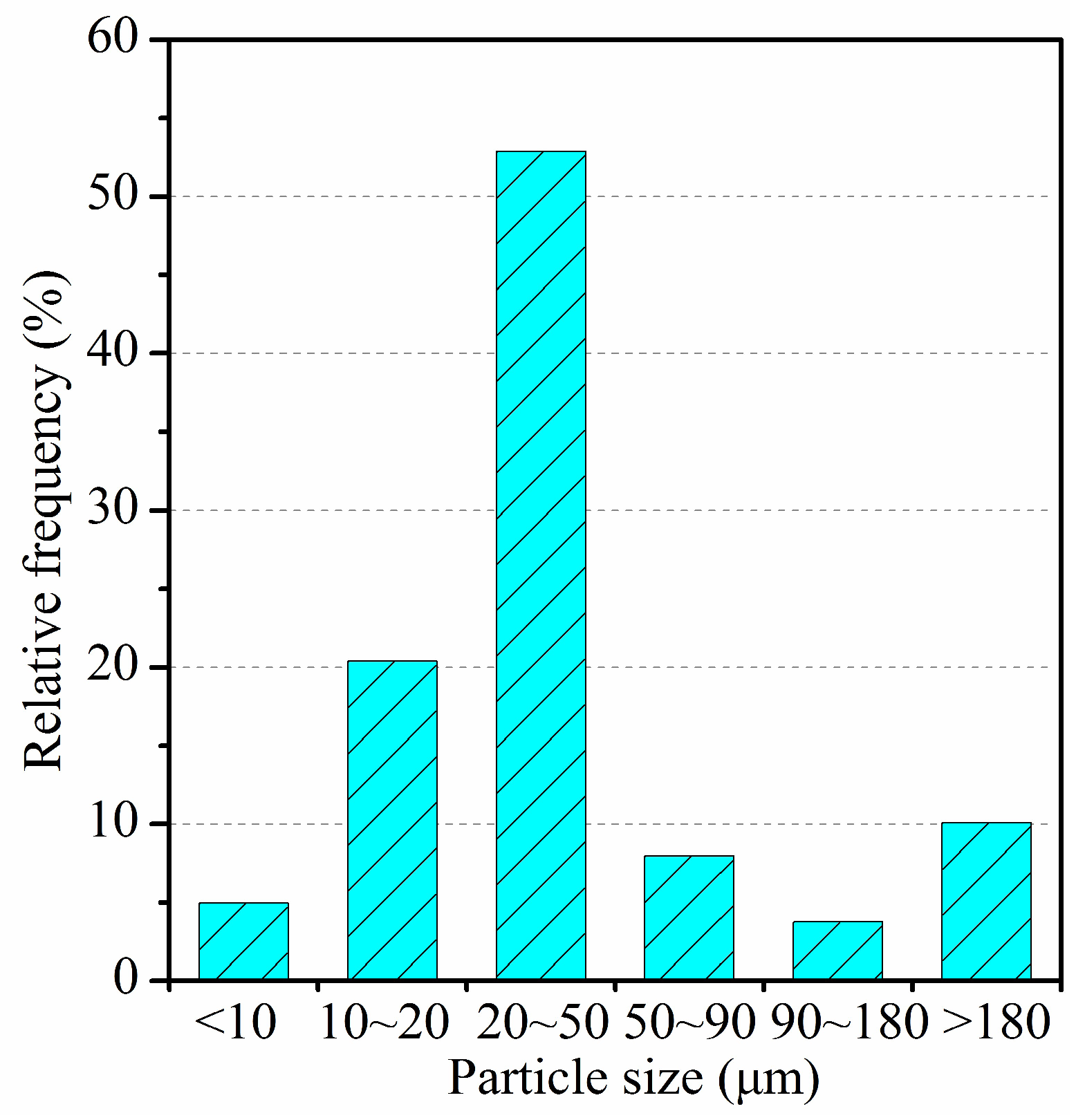
Table 1. It can be seen that dust is composed of many particles of different sizes and shapes, such as flakes, blocks, circles, needles, spheres and so on. The dust particles are pyrite dust particles mainly composed of iron (Fe), calcium (Ca) and sulfur (S). Most particles have different sizes in different directions. The irregularity of dust particles is beneficial to collision and condensation. The particle size distribution of sampled dust is shown in
Figure 6.
As shown in
Figure 6, the particle size of sampled metal dust mainly concentrates in the range of 10–50 μm. More than 78% of metal dust samples have a particle size of less than 50 μm.
3.1.1. Measurement of Atomization Parameters
The ultrasonic atomizer is made of brass. It has two interfaces, one connecting compressed air and the other connecting water. The interfaces are all 12.7 mm pipe threads. The effects of air pressure and water volume on atomization were investigated. The air pressure and water volume are directly collected through the pressure gauge and flowmeter installed in each pipeline. Based on the experimental results, the relationships between the pressure, water volume and the atomization parameters are analyzed, and the optimum working conditions of the atomizer are obtained.
The atomization parameters mainly include the dispersion and quantity of fog droplets. The parameters were measured by using split laser particle size analyzer (Winner 318A; test range: 1–323 μm; accuracy: <3%). The instrument adopts Fraunhofer diffraction principle and typical parallel optical path design. It is equipped with high-performance and high-power laser. It can meet the requirements of complex sampling environment and large particle size distribution (test range 1–323 μm). The sprayer is placed above the split spray laser particle sizer. When the water mist is ejected downward, the parameters of the mist flow within the test range are measured automatically in real time. The measurement of the atomization parameters is shown in
Figure 7.
During the experiments, the number and size distributions of water mist particles were measured in the test area. Due to the water mist particles emitted by the ultrasonic atomizer being very fine and easy to evaporate, the measurement of water fog particle size needs to be done in a certain relative humidity environment for a specific period. Therefore, the test time for measuring the water mist particle size could be controlled within 0.5–1 min to make the results more accurate.
3.1.2. Performance of Experimental Nozzles
Six types of nozzle were used for the experiment. The performances of the nozzles are shown in
Table 2. The results show that the spray angle of nozzle QA-107 is the largest (105°) and the jet range is relatively far away (2.1 m). It can capture dust in a wider range. In addition, its water consumption and water pressure are appropriate, and its economy is good. Based on these, it is reasonable to choose QA-107 to equip with the pressure sprayer.
3.2. Experiment for Dust Suppression
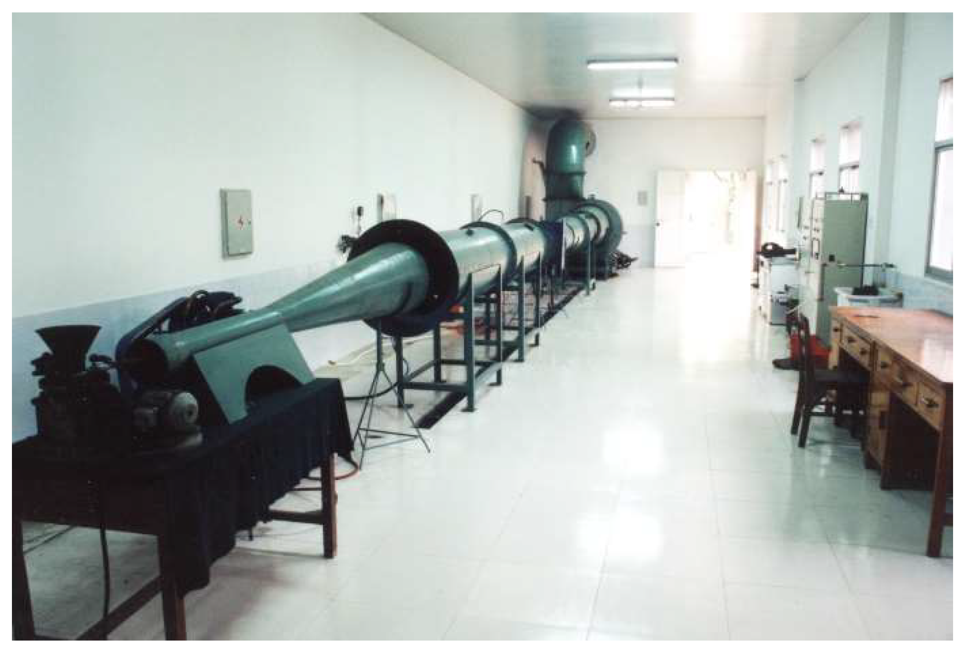
The experimental device of SCDC is shown in
Figure 8. The device consists of the following system: a dust generating system, an air supply system, a water supply system, a dust collector prototype (length: 1780 mm; width: 1585 mm; height: 3700 mm; handling air volume: 8000–10000 m
3/h; operation resistance: 500–1000 pa), a test system, a dehydration system, an air flow regulating valve, a centrifugal fan, a frequency converter and a sensor. The sensors of wind speed, wind pressure, temperature and humidity are set at the inlet and outlet of the dust collector, and the wind speed and resistance loss of the dust collector prototype are obtained.
In the experiment, the disc duster is used to produce dust, and the compressed air produced by the air compressor is used to eject a certain concentration of dust. The dust-laden air flow passes through the dust equalizing cylinder and enters the experimental air cylinder. The exhaust fan is a centrifugal fan (4-72 number 6C; flow: 7367–14734 m3/h; air pressure: 1389-881 Pa). Besides, the frequency converter is used to adjust the air flow and the occurrence of the duster.
4. Results and Discussion
4.1. Atomization Experiment Results
According to the principle of aerodynamics, when the dust airflow encounters water mist particles, the probability of water mist capturing dust in airflow is related to the size of water mist. When the particle size of water mist is large, the dust airflow will directly bypass the water mist; when the particle size of water mist is close to that of dust, it is easier for the two to collide, so the dust is captured. As shown in
Figure 6, the particle size of most metal dust is less than 50 μm. The optimum operating parameters of the ultrasonic atomizer for producing 1–50 μm dense gaseous water mist are studied in this study.
The temperature and relative humidity of the laboratory were about 20 °C and 90% respectively. For the ultrasonic atomizer, the main factors affecting the atomization effect are the pressure and water quantity of the atomizer. The effects of these two factors are considered separately during the experiment. The relationships between air pressure, water volume and fog parameters were analyzed comprehensively. Consequently, the optimum working conditions of the atomizer were obtained.
4.1.1. Effect of Air Pressure on Atomization
The experiment measuring the effect of air pressure on atomization was carried out under the conditions of water volume 20 L/h and water pressure 0.1–0.15 MPa. The results are shown in
Figure 9.
As shown in
Figure 9, there is no linear relationship between the number of droplets and the proportion of droplets below 50 μm and the air pressure. When the number of droplets is the largest, the atomization effect of ultrasonic atomizer is the best.
- (1)
When the water supply of the atomizer is constant, the number of droplets increases first and then decreases with the increase of air pressure. When the air pressure is 0.35 MPa, the number of droplets is the largest. The result is similar to a previous study performed by Gao et al. [
24].
- (2)
With the change of air pressure, the proportion of fog droplets below 50 μm has the same trend as the number of fog droplets. When the air pressure is 0.35 MPa, the proportion of fog droplets is the largest.
- (3)
When the water volume is constant, the droplet size is smaller—more droplets. Additionally, the droplets are well-distributed. Consequently, the corresponding atomization effect is quite good.
4.1.2. Effect of Air Pressure on Atomization
The effect of water volume on atomization was tested for under the air pressure of 0.35 MPa, as shown in
Figure 10.
As shown in
Figure 10, when the pressure is constant, the number of droplets will increase with the increase of water volume. Especially when the water volume is less than 30 L/h, the number of droplets increases significantly. When the amount of water is more than 30 L/h, the increasing trend of droplet number is very small, not even increasing with the increase of water volume. The proportion of fog droplets below 50 μm increases first and then decreases with the increase of water volume under the condition of constant air pressure.
- (1)
The number of fog droplets and the proportion of fog droplets below 50 μm increase with the increase of water content in a certain range. Therefore, increasing the amount of atomized water is conducive to improving the atomization effect.
- (2)
When the water content is more than 30 L/h, the droplet number increases very slowly, but the droplet size increases. Therefore, when the amount of water reaches a certain value, the atomization effect will begin to decline if the amount of water continues to increase.
In order to improve atomization effect, minimize water consumption and air pressure, and avoid the difficulty of equipment maintenance caused by high pressure and large water volume; the influential factors of air pressure and water volume should be considered comprehensively. Additionally, economical and reasonable air supply pressure and water supply quantity should be determined. The results show that the optimum operating conditions of the ultrasonic nebulizer are: air pressure 0.35 MPa, water volume 30 L/h.
4.2. Results of Dust Removal Efficiency
4.2.1. Relationship between Liquid–Gas Ratio and Dust Removal Efficiency
Keeping the velocity of dust airflow at 14.0 m/s, the relationships between different liquid–gas ratios and dust removal efficiency and resistance of SCDC are studied. The results are shown in
Figure 11.
With the increase of the liquid–gas ratio from 0.05 L/m
3 to 0.15 L/m
3, the total dust removal efficiency and the respirable dust removal efficiency of SCDC are both improved, with the latter increasing from 85.28% to 99.35%. Therefore, the increase of liquid–gas ratio is very significant for the dust removal efficiency of respirable dust. As shown in
Figure 11, the total dust removal efficiency is mainly not increased when the liquid–gas ratio is greater than 0.15 L/m
3. However, the respirable dust removal efficiency is decreased significantly. Thus, it can be concluded that the optimum liquid–gas ratio of a swirling curtain dust collector is 0.15 L/m
3.
4.2.2. Relationship between Wind Speed and Dust Removal Efficiency
During the experimental process, the speed of the air flow is regulated by adjusting the speed of the fan motor through the control system inverter. The working pressure and volume of the ultrasonic atomizer and the liquid gas ratio of the pressure sprayer remain unchanged. Dust removal efficiency and resistance of SCDC under different wind speeds were measured with constant water supply and pressure. The results are shown in
Figure 12 and
Figure 13.
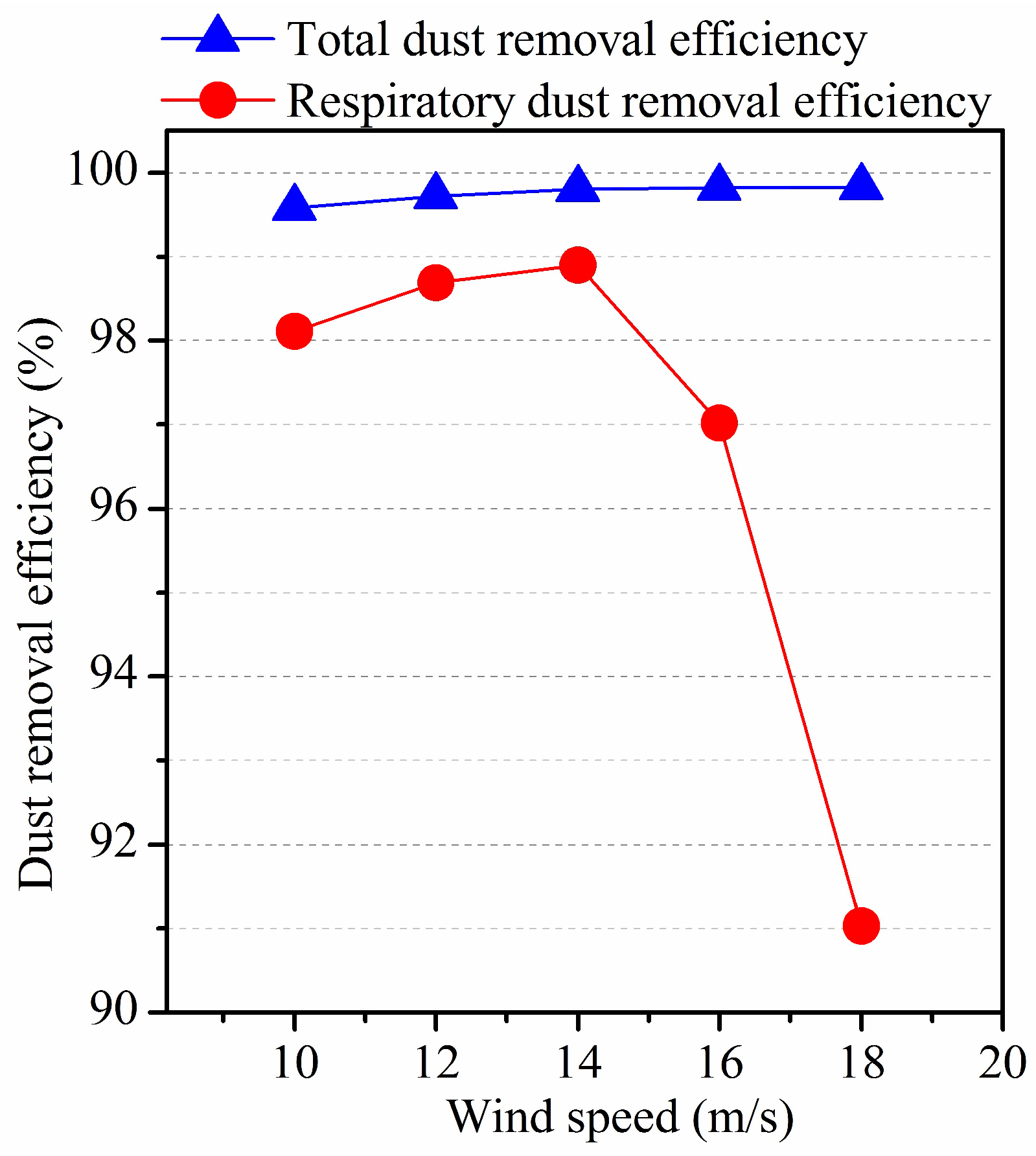
As presented in
Figure 12, the dust removal efficiency increases with the raising of wind speed. When the wind speed is over 14 m/s, the total dust removal efficiency increases slightly. On the contrary, the respirable dust removal efficiency decreases significantly. The main reason is that the wind speed is too high so that the dust-laden air stays in the cyclone for a very short time. Thus, a small part of the dust is carried away with the air flow. Dusty water mist particles cannot settle completely through centrifugation.
As shown in
Figure 13, the resistance of the dust collector also increases with the improvement of wind speed. When the wind speed reaches 16 m/s, the resistance increases rapidly as the wind speed continues to increase.
According to the above description, there is an optimum range of wind speed for SCDC, whose value is 14–16 m/s. Given this situation, the resistance of the dust collector is about 800–1000 Pa; the total dust removal efficiency is greater than 99.8%; and the respiratory dust removal efficiency is more than 97%.
5. Field Application
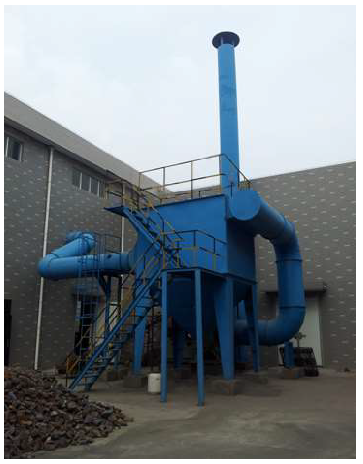
In order to study the dedusting effect of the swirling curtain dust collector, the measurements of dust concentration at number 4 and number 5 transfer stations in Luohe Iron Mine located in east China were performed. The number 4 and number 5 transfer stations were firstly designed to have a set of ultrasonic atomization dust suppression systems for dust removal of number 8 and number 9 belt conveyor head, and number 9 and number 10 belt conveyor feeding. However, the atomizer has been clogged up with dust and the dust removal effect is terrible. Thus, two sets of high-efficiency swirling curtain dust collectors are used for dust collecting in number 4 and number 5 transfer stations (XLWM-1.5, dust removal air volume: 15,000–17,000 m3/h, resistance: 800–1000 Pa). In addition, two fans were matched with air volume 18,904–22,999 m3/h and air pressure 3664–3488 Pa.
In order to evaluate the dedusting effects, four dust sampling points were placed when the transfer station was operating. Two of the points were positioned at the blanking area of number 8 and number 9 belt conveyor, and the other two were located at the end unit of number 9 and number 10 belt conveyor. The testing points were set at a height of 1.5 m above the ground. The concentrations of the dust were measured by using dust-measuring instrument (TH-880 F; sampling flow: 5–60 L/min; accuracy: ±2.5%) and inclined manometer (YYT-2000B; range: 0–2000 Pa; accuracy: 1%). For the purpose of reducing the measurement errors, three group tests were conducted. The mean value of several measurements was taken for analysis.
Table 3 lists the dust concentrations before/after installing the swirling curtain dust collector.
As shown in
Table 3, the dust concentration decreased from 32.7 mg/m
3 to 4.3 mg/m
3 on average, when the SCDC was adopted.
Table 4 shows the dust removal efficiency of SCDC used in number 4 and number 5 transfer stations.
The dust removal efficiency in both number 4 and number 5 transfer station was over 99.8%. The average dust concentration at the outlet of SCDC is far below 20 mg/m
3, which is stipulated by Chinese standard GB 28661-2012 [
25].
Figure 14 shows the comparison of dust distribution before/after SCDC used in transfer station of Luohe Iron Mine in China. Obviously, the application of SCDC is effective at reducing the dust in a transfer station.
Therefore, it could be concluded that the device designed in this study would be ideal for the production system of a mine.
6. Conclusions
A kind of swirling curtain dust collector (SCDC) was designed for removing dust produced in a metal mine. This dust collector consists of a dust collector box, a spray device, a bidirectional swirling-dedusting-dewatering device and a dust slurry collector. The performance of the SCDC was studied under different operating parameters. The main conclusions are as follows:
- (1)
The proposed device is a kind of comprehensive wet dust collector. After the dust airflow entered the dust collector, it was mixed with the water curtain produced by ultrasonic nebulizer and pressure sprayer. A mixture of dust and water was formed after collision, interception and diffusion. Finally, the dust-water mixture was thrown onto the cylinder wall and removed under the centrifugal action of the cyclone.
- (2)
The optimum working conditions of the device were as follows: air pressure: 0.35 MPa, water volume: 30 L/h; liquid–gas ratio: 0.15 L/m3; wind speed: 14–16 m/s. Under the above conditions, the suppression efficiency of total dust and respirable dust were over 99.8% and 97%, respectively.
- (3)
The proposed device was applied in Luohe Iron Mine located in China. It was installed on transfer station and the dust removal effect was evaluated comparatively. The results of the application measurements indicated that the mean dust concentration decreased from 32.7 mg/m3 to 4.3 mg/m3 when the SCDC was used. The dust removal efficiency was over 99.8%. The average dust concentration at the outlet of SCDC was less than 20 mg/m3, which is stipulated by Chinese standard GB 28661-2012. Based on the above discussion, the proposed device was an ideal device with which to replace the traditional Venturi wet scrubber. It is also suitable for a wider utilization.
Author Contributions
Conceptualization, G.L.; methodology, G.L.; investigation, G.L.; writing—original draft preparation, G.L. and J.H.; writing—review and editing, J.H. and X.H.; supervision, H.Q.; project administration, X.H. and H.Q. All authors have read and agreed to the published version of the manuscript.
Funding
This research was funded by the National Key R&D Program of China “Physicochemical dust removal technology and equipment in mining and transportation of metal and nonmetallic mines during the 13th Five-year Plan Period” (grant number 2017YFC0805204), the Science research project of Hunan Provincial Department of Education of China (grant number 18C0322) and the Doctoral Scientific Research Foundation of Hunan University of Science and Technology (grant number E51853).
Acknowledgments
This research was funded by the “Physicochemical dust removal technology and equipment in mining and transportation of metal and nonmetallic mines during the 13th Five-year Plan Period” (grant number 2017YFC0805204), the Science research project of Hunan Provincial Department of Education of China (grant number 18C0322) and the Doctoral Scientific Research China National Key R&D Program for the Foundation of Hunan University of Science and Technology (grant number E51853).
Conflicts of Interest
The authors declare no conflict of interest.
References
- Zhao, Y.; Chen, S.; Tan, X. The mechanism and application of dry dust removal technology in long tunnel construction. Mod. Tunn. Technol. 2014, 51, 200–205. [Google Scholar]
- Hu, S.; Zhuo, W.; Feng, G. Temporal and Spatial Distribution of Respirable Dust After Blasting of Coal Roadway Driving Faces: A Case Study. Minerals 2015, 5, 679–692. [Google Scholar] [CrossRef]
- Ren, W.; Wang, D.; Guo, Q.; Zuo, B. Application of foam technology for dust control in underground coal mine. Int. J. Min. Sci. Technol. 2014, 24, 13–16. [Google Scholar] [CrossRef]
- Xie, Y.; Fan, G.; Dai, J.; Song, X. New Respirable Dust Suppression Systems for Coal Mines. J. China Univ. Min. Technol. 2007, 17, 321–325. [Google Scholar] [CrossRef]
- Nie, W.; Liu, Y.; Cheng, W.; Zhou, G.; Xue, J.; Ma, X. Simulation experiment on multi-direction whirling air curtain preventing dust diffusion. J. Cent. South Univ. 2016, 47, 350–358. [Google Scholar]
- Wen, N.; Liu, Y.; Hao, W.; Wei, W.; Peng, H.; Peng, C.; Yun, H.; Hu, J. The development and testing of a novel external-spraying injection dedusting device for the heading machine in a fully-mechanized excavation face. Process Saf. Environ. Prot. 2017, 109, 716–731. [Google Scholar]
- Lu, X.; Zhu, H.; Wang, D. Investigation on the new design of foaming device used for dust suppression in underground coal mines. Powder Technol. 2017, 315, 270–275. [Google Scholar] [CrossRef]
- Wang, H.; Wang, D.; Ren, W.; Lu, X.; Han, F.; Zhang, Y. Application of foam to suppress rock dust in a large cross-section rock roadway driven with roadheader. Adv. Powder Technol. 2013, 24, 257–262. [Google Scholar] [CrossRef]
- Li, S.; Zhou, F.; Wang, F.; Xie, B. Application and research of dry-type filtration dust collection technology in large tunnel construction. Adv. Powder Technol. 2017, 28, 3213–3221. [Google Scholar]
- Hu, S.; Huang, Y.; Feng, G.; Shao, H.; Liao, Q.; Gao, Y.; Hu, F. Investigation on the design of atomization device for coal dust suppression in underground roadways. Process Saf. Environ. Prot. 2019, 129, 230–237. [Google Scholar] [CrossRef]
- Cheng, W.; Nie, W.; Zhou, G.; Yu, Y.; Ma, Y.; Xue, J. Research and practice on fluctuation water injection technology at low permeability coal seam. Saf. Sci. 2012, 50, 851–856. [Google Scholar] [CrossRef]
- Zhao, Z. Study of technology of variable-frequency pulse water infusion into coal seam. J. Min. Saf. Eng. 2008, 25, 486–489. [Google Scholar]
- Lu, X.; Wang, D.; Wang, H.; Hu, F.; Ren, W. Research and application of newly dedusting technology with gas-liquid two-phase mixing foaming. J. Saf. Sci. Technol. 2012, 8, 16–20. [Google Scholar]
- Wang, D.; Lu, X.; Wang, H.; Chen, M. A new design of foaming agent mixing device for a pneumatic foaming system used for mine dust suppression. Int. J. Min. Sci. Technol. 2016, 26, 187–192. [Google Scholar] [CrossRef]
- Lu, X.; Wang, D.; Xu, C.; Zhu, C.; Wei, S. Experimental investigation and field application of foam used for suppressing roadheader cutting hard rock in underground tunneling. Tunn. Undergr. Space Technol. 2015, 49, 1–8. [Google Scholar] [CrossRef]
- Shuai, S.; Yang, X.G.; Zhou, J.W. Numerical analysis of different ventilation schemes during the construction process of inclined tunnel groups at the Changheba Hydropower Station, China. Tunn. Undergr. Space Technol. 2016, 59, 157–169. [Google Scholar]
- Wei, N.; Jiang, Z.; Tian, D. Numerical simulation of the factors influencing dust in drilling tunnels: Its application. Int. J. Min. Sci. Technol. 2011, 21, 11–15. [Google Scholar] [CrossRef]
- Sun, B.; Cheng, W.; Wang, J.; Wang, H.; Ma, Y. Development of Venturi negative-pressure secondary dedust device and application of local spray closure technique. Adv. Powder Technol. 2019, 30, 42–54. [Google Scholar] [CrossRef]
- Li, G.; Wu, C. Research on mechanism and parameters optimization of ultrasonic atomization technique for dust removal. China Saf. Sci. J. 2015, 25, 108–113. [Google Scholar]
- Wang, Y.; Xu, K.; Wang, B.; Zhang, J. Hydrogen inhibition in a wet aluminum dust collection system using dichromate solution. RSC Adv. 2017, 7, 47867–47876. [Google Scholar] [CrossRef]
- Kirpalani, D.M.; Suzuki, K. Ethanol enrichment from ethanol–water mixtures using high frequency ultrasonic atomization. Ultrason. Sonochem. 2011, 18, 1012–1017. [Google Scholar] [CrossRef] [PubMed]
- Carlos, M.; Romo, K. A qualitative study of atmospheric aerosols and particles deposited on flat membrane surfaces by microscopy and other techniques. Powder Technol. 2006, 161, 235–241. [Google Scholar]
- Su-Ping, M.A.; Prof, A. Study on Efficiency of Dust Suppression by Mist Spray and Its Matched Parameters. China Saf. Sci. J. 2006, 16, 84–88. [Google Scholar]
- Gao, G.; Wang, C.; Kou, Z. Experimental studies on the spraying pattern of a swirl nozzle for coal dust control. Appl. Sci. 2018, 8, 1770. [Google Scholar] [CrossRef]
- GB 28661-2012. Emission Standard of Pollutants for Mining and Mineral Processing Industry; China Environmental Science Press: Beijing, China, 2012. [Google Scholar]
© 2020 by the authors. Licensee MDPI, Basel, Switzerland. This article is an open access article distributed under the terms and conditions of the Creative Commons Attribution (CC BY) license (http://creativecommons.org/licenses/by/4.0/).


