Article

Solving a System of Differential Equations Containing a Diffusion Equation with Nonlinear Terms on the Example of Laser Heating in Silicon

1
Department of Physics and OPTIMAS Research Center, Technical University of Kaiserslautern, 67663 Kaiserslautern, Germany
2
Institute of Physics and Center for Interdisciplinary Nanostructure Science and Technology (CINSaT), University of Kassel, 34125 Kassel, Germany
3
Center for Free-Electron Laser Science CFEL, Deutsches Elektronen-Synchrotron DESY, Notkestr. 85, 22607 Hamburg, Germany
4
P. N. Lebedev Physical Institute of Russian Acad. Sci., 119991 Moscow, Russia
*
Author to whom correspondence should be addressed.
Appl. Sci. 2020, 10(5), 1853; https://doi.org/10.3390/app10051853
Submission received: 18 November 2019 / Revised: 24 February 2020 / Accepted: 27 February 2020 / Published: 8 March 2020
(This article belongs to the Special Issue Ultrafast Electronic Dynamics in SolidsⅡ)

Abstract

:
We present a finite-difference integration algorithm for solution of a system of differential equations containing a diffusion equation with nonlinear terms. The approach is based on Crank–Nicolson method with predictor–corrector algorithm and provides high stability and precision. Using a specific example of short-pulse laser interaction with semiconductors, we give a detailed description of the method and apply it to the solution of the corresponding system of differential equations, one of which is a nonlinear diffusion equation. The calculated dynamics of the energy density and the number density of photoexcited free carriers upon the absorption of laser energy are presented for the irradiated thin silicon film. The energy conservation within 0.2 % has been achieved for the time step 10 8 times larger than that in case of the explicit scheme, for the chosen numerical setup. The implemented Fortran source code is available in the Supplementary Materials. We also present a few examples of successful application of the method demonstrating its benefits for the theoretical studies of laser–matter interaction problems. Finally, possible extension to 2 and 3 dimensions is discussed.

1. Introduction

Many phenomena occurring in nature for their investigation can be described via mathematical models based on time-dependent nonlinear diffusion equations [1]. Examples include genetics [2,3], image processing [4], quantum mechanics [5], and laser–material interactions [6]. Although during the last decades a big effort has been undertaken to find efficient numerical schemes for solution of the corresponding mathematical problem, some of the applications are still a challenging task. Specifically, the efforts in model implementation as well as their demands on the computational power during processing can substantially hinder the theoretical interpretation of the investigated problem. In this work, we consider an application of the nonlinear parabolic diffusion equation to describe the response of solids to an ultrashort laser pulse irradiation. Apart from the insights into the material structure, this topic is important for the description of laser machining [7,8,9] and nanostructuring experiments [10,11,12] with applications in biotechnology [13] and IT [14,15]. For metals, the problem may be mathematically formulated in the form of frequently used Two-Temperature Model (TTM) [16], whereas for semiconductors, a similar TTM-like approach has been proposed [17]. The latter is based on the system of partial differential equations, reflecting the conservation laws in the atomic subsystem of a solid and its electronic subsystem. Although it is relatively simple to apply an explicit finite-difference numerical scheme to solve such systems in metals [18] or semiconductors [19], the corresponding stability criteria demand the integration time steps to be small, causing high computational costs as a result. The main restriction on the time step often comes from the nonlinear diffusion equation describing the carrier heat conduction process [20]. One of the possibilities to increase the time step of diffusion equation is to use implicit or semi-implicit integration schemes. For instance, the Crank–Nicolson semi-implicit scheme [21,22] provides unconditionally stable solution when applied to linear diffusion equations. However, this approach is not directly applicable when nonlinear terms play an important role.
In this work, we present a semi-implicit finite-difference method for the solution of a system of differential equations—one of which is a diffusion equation with nonlinear terms—and apply it to model short laser pulse interaction with silicon. The presented approach is based on Crank–Nicolson method with predictor–corrector algorithm and provides high stability and precision. It has been already successfully applied for the investigation of ultrashort laser interaction with metals [23] and semiconductors [24,25,26]. Section 2 describes the theoretical model and presents the system of equations where a nonlinear diffusion equation results in strong restriction on the time step for the explicit integration algorithm. In Section 3, we give a detailed description of semi-implicit numerical solution scheme, which was modified with predictor–corrector algorithm to account for the nonlinearity in the diffusion equation. Further, in Section 4, the calculation results for a particular set of parameters are presented and the energy conservation versus the applied iteration time step is investigated. Section 5 mentions the existing works, in which this approach has been successfully utilized, and suggests possible improvements for the application of the presented approach in two-dimensional (2D) and three-dimensional (3D) cases. Finally, in Section 6, we give a summary of our results.

2. Model Description

To demonstrate the application of the finite-difference scheme, we use an example of laser irradiation on silicon. Below, we present the full set of nonlinear differential equations for the continuum description of electron density and electron/phonon energy density dynamics in silicon under ultrashort laser irradiation. For the derivation of the following expressions we refer to the works in [17] and [25]. Due to laser pulse irradiation (in this example Ti:Sapphire laser at 800 n m wavelength), free carriers are generated in the material, electrons in the conduction band, and holes in the valence band. Both types of carriers are assumed to quickly equilibrate in the corresponding bands and move together due to the Dember field preventing charge separation [27]. To each of them, we apply separate Fermi–Dirac distributions with different chemical potentials, ϕ e and ϕ h , for the electrons and holes, respectively, but with shared carrier density n and temperature T e (two-chemical potentials model). The reduced chemical potentials are defined as follows,
η e = ϕ e E C k B T e and η h = E V ϕ h k B T e ,
where E C and E V are the conduction and valence band energy levels, respectively, so the energy gap is E g = E C E V . The integration of the carrier distribution functions over the energy leads to the expressions for the carrier density (parabolic bands are assumed):
n = 2 m c * k B T e 2 π 2 3 2 F 1 2 η c ,
where subscript c stands as e for electrons and h for holes. The Fermi–Dirac integral is defined as
F ξ η c = 1 Γ ξ + 1 0 x ξ 1 + exp x η c d x .
The carrier current is the sum of contributions from the electrons and the holes:
J = D [ n + n k B T e H 1 2 1 2 η e + H 1 2 1 2 η h 1 E g + n T e 2 H 0 1 η e + H 0 1 η h H 1 2 1 2 η e + H 1 2 1 2 η h 3 2 T e ] ,
where H ζ ξ η c F ξ η c / F ζ η c and the ambipolar diffusion coefficient is
D = k B T e q e μ e μ h H 1 2 0 η e H 1 2 0 η h μ e H 1 2 0 η e + μ h H 1 2 0 η h H 1 2 1 2 η e + H 1 2 1 2 η h
with q e the elementary charge. Ambipolar energy flow is the sum of diffusion and thermal energy currents inside the carrier subsystem and can be written as
W = E g + 2 k B T e H 0 1 η e + H 0 1 η h J κ e + κ h T e .
The dynamics of semiconductors under the irradiation of ultrashort laser pulses can be modeled with the system of three continuum equations [17,28]: continuity equation for free carrier density and two coupled energy balance equations, one for the carriers and one for atoms:
n t + · J = S n γ n 3 + δ T e n ,
C e h T e t = S u · W C e h τ e p T e T a n t E g + 3 2 k B T e H 1 2 3 2 η e + H 1 2 3 2 η h n E g n n t + E g T a T a t 3 2 k B T e n n t 1 H 1 2 3 2 η e H 1 2 3 2 η e η e n + 1 H 1 2 3 2 η h H 1 2 1 2 η h η h n ,
C a T a t = · k a T a + C e h τ e p T e T a .
The meanings of symbols in Equations (7) to (9) are the following, S n is the source of new carriers (excitation rate of new carriers by the laser), S u describes the energy source (rate of laser energy absorption), and T a is atomic temperature. The terms on the right hand side of Equation (7) are responsible for the carrier generation, Auger recombination, and impact ionization, consequently. Equation (8) describes the energy balance in the photoexcited electron–hole pairs and is a nonlinear diffusion equation. The last Equation (9) describes the energy balance in the atomic subsystem. C e h is specific heat capacity of the electron–hole pairs:
C e h = 3 2 n k B [ H 1 2 3 2 η e + H 1 2 3 2 η h + T e η e T e 1 H 1 2 3 2 η e H 1 2 1 2 η e + T e η h T e 1 H 1 2 3 2 η h H 1 2 1 2 η h ] .
The total energy of electron–hole pairs consists of the energy gap and the kinetic energy of electrons and holes (taking into account the Fermi statistics),
u = n E g n , T e + 3 2 n k B T e H 1 2 3 2 η e + H 1 2 3 2 η h .
The parameters used in the calculations as well as the meanings of other symbols are presented in Table 1.
To present an example of the model application, we use the following source terms. The rate of free carrier density growth, S n , and the corresponding rate of their energy increase, S u , are given by
S n = α I a b s r , t ω + β I a b s 2 r , t 2 ω ,
S u = α I a b s r , t + β I a b s 2 r , t + Θ n I a b s r , t .
In the last two equations, the first and second terms on the right hand side represent the influence of one- and two-photon absorption, respectively, and the third term in the second equation represents the laser energy absorption by the excited free carriers.
One-dimensional (1D) laser heating problem is analyzed in this work. The laser is focused on the material surface. The corresponding form of laser intensity at the surface ( z = 0 ) in this case is
I a b s 0 , t = 1 R T a ς π Φ i n c t p exp ς t 3 t p / t p 2 ,
where Φ i n c is the incident fluence, ς = 4 ln 2 , and R ( T a ) is the reflectivity function (see Table 1). In the present calculations, the center of Gaussian pulse is shifted in time from the initial time, t = 0 , to 3 pulse duration times, 3 t p , which in turn is defined as the pulse width at the half of maximum.
The dependence of the laser pulse intensity, I a b s , on depth can be found upon the solution of differential equation of the attenuation process:
d I a b s d z = α I a b s z , t β I a b s 2 z , t Θ n I a b s z , t ,
where z is the depth into sample; the terms on the right side are responsible for one- and two-photon absorption, and for the free-carrier absorption processes.
Thus, from the system of Equations (7) to (9), we can fully determine the dynamics of n, T e , and T a in 1D using the following initial and boundary conditions, suitable for a free standing film:
T a z , 0 = T e z , 0 = 300   K , n z , 0 = n e q = 1 × 10 16   m 3 , ref . [ 29 ] , J 0 , t = J L , t = 0 , W 0 , t = W L , t = 0 , k a T a z 0 , t = k a T a z L , t = 0 ,
where L is the thickness of the sample.
Owing to its similarity with an ordinary well-known TTM model [16], but with an additional equation for free carriers density n, we refer to the described approach as nTTM model, as it was suggested in [24].

3. Numerical Solution Scheme

To solve the system of Equations (7) to (9), we utilize the finite difference grid mesh presented in Figure 1. Sample is divided into cells as indicated, and the local thermodynamic parameters are calculated in each cell. The spatial derivatives of n , T e , T a , J , W , k a T a z , and E g at the interior points are approximated with the central differences, and those at the boundaries are evaluated with the first-order approximation. Equations (7) and (9) are initially solved explicitly ( T T e ):
n i k + 1 n i k Δ t + J i k J i 1 k Δ x = ( S n ) i k γ ( n i k ) 3 + δ i k n i k ,
( C a ) i k ( T a ) i k + 1 ( T a ) i k Δ t = 1 ( Δ z ) 2 ( k a ) i + 1 2 k ( T i + 1 k T i k ) ( k a ) i 1 2 k ( T i k T i 1 k ) + ( C e h ) i k ( τ e p ) i k T i k ( T a ) i k ,
where index i is connected to the cell number (see Figure 1) and k to the moment of time.
Therefore, before solving Equation (8) we already have the predictions for n k + 1 and ( T a ) k + 1 . The approach is based on the Crank–Nicolson semi-implicit scheme [21,22]. Equation (8) can be rewritten in the following finite-difference form:
T i k + 1 T i k Δ t = ( 1 ψ ) f i k + ψ f i k + 1 .
The right-hand side contains parameter ψ , which can be 0 for explicit scheme, 1 for implicit, and 1 2 for semi-implicit. The function f i k can be found from:
( C e h ) i k f i k = ( S u ) i k W i k W i 1 k Δ z ( C e h ) i k ( τ e p ) i k T i k ( T a ) i k n t i k ( E g ) i k + 3 2 k B T i k H 1 2 3 2 ( η e ) + H 1 2 3 2 ( η h ) i k n i k E g n i k n t i k + E g T a i k T a t i k 3 2 k B T i k n i k n t i k × η e n i k 1 H 1 2 3 2 ( η e ) i k H 1 2 1 2 ( η e ) i k + η h n i k 1 H 1 2 3 2 ( η h ) i k H 1 2 1 2 ( η h ) i k ,
where W i k is defined according to Figure 1 (between the cells) and Equation (6):
W i k = ( E g ) i + 1 2 k + 2 k B T i + 1 2 k [ H 0 1 ( η e ) + H 0 1 ( η h ) ] i + 1 2 k × J i k ( k e + k h ) i + 1 2 k T i + 1 k T i k Δ z
Analogously, according to Figure 1 and Equation (4), the carrier current is
J i k = D i k [ n i + 1 k n i k Δ z + n i + 1 2 k k B T i + 1 2 k H 1 2 1 2 ( η e ) + H 1 2 1 2 ( η h ) i + 1 2 k 1 ( E g ) i + 1 k ( E g ) i k Δ z . + n i + 1 2 k T i + 1 2 k 2 H 0 1 ( η e ) + H 0 1 ( η h ) i + 1 2 k H 1 2 1 2 ( η e ) + H 1 2 1 2 ( η h ) i + 1 2 k 3 2 T i + 1 k T i k Δ z . ]
with
D i k = k B T i + 1 2 k q e μ e μ h ( H 1 2 0 η e ) i + 1 2 k ( H 1 2 0 η h ) i + 1 2 k μ e ( H 1 2 0 η e ) i + 1 2 k + μ h ( H 1 2 0 η h ) i + 1 2 k H 1 2 1 2 η e + H 1 2 1 2 η h i + 1 2 k .
Any function in between cells can be found by averaging
A i + 1 2 = 1 2 ( A i + A i + 1 ) .
The Fermi–Dirac integrals were calculated using GNU Scientific Library [40] and stored in the tables to speed up the calculations. η c n can be found by derivative of Equation (2) by the carrier density:
η c n = 1 2 2 π 2 m c * k B T e 3 2 1 F 1 2 ( η c ) ;
η c T e can be found by taking the derivative of Equation (2) by the electronic temperature:
n c T e = 3 2 n × ( T e ) 5 2 π 2 m c * k B 3 2 1 F 1 2 ( η c ) .
The boundary conditions can be rewritten in the finite-difference form as follows,
n 1 k + 1 n 1 k Δ t + 2 J 1 k Δ z = ( S n ) 1 k γ ( n 1 k ) 3 + δ 1 k n 1 k ;
( C a ) 1 k ( T a ) 1 k + 1 ( T a ) 1 k Δ t = 2 ( Δ z ) 2 ( k a ) 1 + 1 2 k ( T 2 k T 1 k ) + ( C e h ) 1 k ( τ e p ) 1 k T 1 k ( T a ) 1 k ;
T 1 k + 1 T 1 k Δ t = ( 1 ψ ) f 1 k + ψ f 1 k + 1
with
( C e h ) 1 k f 1 k = ( S u ) 1 k 2 W 1 k Δ z ( C e h ) 1 k ( τ e p ) 1 k T 1 k ( T a ) 1 k n t 1 k ( E g ) 1 k + 3 2 k B T 1 k H 1 2 3 2 ( η e ) + H 1 2 3 2 ( η h ) 1 k n 1 k E g n 1 k n t 1 k + E g T a 1 k T a t 1 k 3 2 k B T 1 k n 1 k n t 1 k × η e n 1 k 1 H 1 2 3 2 ( η e ) 1 k H 1 2 1 2 ( η e ) 1 k + η h n 1 k 1 H 1 2 3 2 ( η h ) 1 k H 1 2 1 2 ( η h ) 1 k ;
and on the other edge
n N k + 1 n N k Δ t 2 J N k Δ z = ( S n ) N k γ ( n N k ) 3 + δ N k n N k ;
( C a ) N k ( T a ) N k + 1 ( T a ) N k Δ t = 2 ( Δ z ) 2 ( k a ) N 1 2 k ( T N k T N 1 k ) + ( C e h ) N k ( τ e p ) N k T N k ( T a ) N k ;
T N k + 1 T N k Δ t = ( 1 ψ ) f N k + ψ f N k + 1
with
( C e h ) N k f N k = ( S u ) N k + 2 W N k Δ z ( C e h ) N k ( τ e p ) N k T N k ( T a ) N k n t N k ( E g ) N k + 3 2 k B T N k H 1 2 3 2 ( η e ) + H 1 2 3 2 ( η h ) N k n N k E g n N k n t N k + E g T a N k T a t N k 3 2 k B T N k n N k n t N k × η e n N k 1 H 1 2 3 2 ( η e ) N k H 1 2 1 2 ( η e ) N k + η h n N k 1 H 1 2 3 2 ( η h ) N k H 1 2 1 2 ( η h ) N k .
All the other equations and connections between variables at the boundaries stay the same and can be straightforwardly obtained by substituting i = 1 and i = N into Equations (17), (21), (25) and (26).
At the current time step, k, we do not have any information about the following parameters from the future time step k + 1 ,
T i 1 k + 1 , T i k + 1 , T i + 1 k + 1 , n t i k + 1 , T a t i k + 1 , ( S u ) i k + 1 , ( C e h ) i k + 1 , J i k + 1 , H 1 2 3 2 ( η e ) i k + 1 , H 1 2 3 2 ( η h ) i k + 1 , H 1 2 1 2 ( η e ) i k + 1 , H 1 2 1 2 ( η h ) i k + 1 , η e n i k + 1 , η h n i k + 1 , η e T e i k + 1 , η h T e i k + 1 .
Initially we set them all except the first three to be equal to the corresponding old values (at time step k):
A i k + 1 ( 0 ) = A i k .
Here, ( 0 ) means the 0th step of the corrector. With this assumption, Equation (19) becomes
a i T i 1 k + 1 + b i T i k + 1 + c i T i + 1 k + 1 = r i ,
which can be represented as a tridiagonal system of equations,
b 1 c 1 0 a 2 b 2 c 2 a 3 b 3 c N 1 0 0 a N b N × T 1 k + 1 T 2 k + 1 T N 1 k + 1 T N k + 1 = r 1 r 2 r N 1 r N ,
where
a i = ψ Δ t Δ z ( C e h ) i k + 1 k B [ H 0 1 ( η e ) + H 0 1 ( η h ) ] i 1 2 k + 1 × J i 1 k + 1 + ( k e + k h ) i 1 2 k + 1 / Δ z ,
b i = 1 ψ Δ t ( C e h ) i k + 1 × ( k B Δ z H 0 1 ( η e ) + H 0 1 ( η h ) i + 1 2 k + 1 × J i k + 1 + k B Δ z H 0 1 ( η e ) + H 0 1 ( η h ) i 1 2 k + 1 × J i 1 k + 1 . ( k e + k h ) i 1 2 k + 1 + ( k e + k h ) i + 1 2 k + 1 / ( Δ z ) 2 ( C e h ) i k + 1 / ( τ e p ) i k + 1 3 2 ( n t ) i k + 1 k B H 1 2 3 2 ( η e ) + H 1 2 3 2 ( η h ) i k + 1 3 2 k B n i k + 1 n t i k + 1 × η e n i k + 1 1 H 1 2 3 2 ( η e ) i k + 1 H 1 2 1 2 ( η e ) i k + 1 + η h n i k + 1 1 H 1 2 3 2 ( η h ) i k + 1 H 1 2 1 2 ( η h ) i k + 1 . ) ,
c i = ψ Δ t Δ z ( C e h ) i k + 1 k B [ H 0 1 ( η e ) + H 0 1 ( η h ) ] i + 1 2 k + 1 × J i k + 1 ( k e + k h ) i + 1 2 k + 1 / Δ z ,
r i = T i k + ( 1 ψ ) Δ t ( C e h ) i k f i k + ψ Δ t ( C e h ) i k + 1 × ( S i k + 1 ( E g ) i + 1 2 k + 1 × J i k + 1 Δ z + ( E g ) i 1 2 k + 1 × J i 1 k + 1 Δ z . + ( C e h ) i k + 1 ( τ e p ) i k + 1 ( T a ) i k + 1 ( n t ) i k + 1 ( E g ) i k + 1 n i k + 1 E g n i k + 1 n t i k + 1 + E g T a i k + 1 T a t i k + 1 )
for i = 2 , , N 1 , and the boundary conditions are
b 1 = 1 ψ Δ t ( C e h ) 1 k + 1 × ( k B Δ z H 0 1 ( η e ) + H 0 1 ( η h ) 1 k + 1 × J 1 k + 1 ( k e + k h ) 3 2 k + 1 ( Δ z ) 2 ( C e h ) 1 k + 1 / ( τ e p ) 1 k + 1 3 2 k B ( n t ) 1 k + 1 H 1 2 3 2 ( η e ) + H 1 2 3 2 ( η h ) 1 k + 1 3 2 k B n 1 k + 1 n t 1 k + 1 × η e n 1 k + 1 1 H 1 2 3 2 ( η e ) 1 k + 1 H 1 2 1 2 ( η e ) 1 k + 1 + η h n 1 k + 1 1 H 1 2 3 2 ( η h ) 1 k + 1 H 1 2 1 2 ( η h ) 1 k + 1 ) ,
c 1 = ψ 2 Δ t Δ z ( C e h ) 1 k + 1 k B [ H 0 1 ( η e ) + H 0 1 ( η h ) ] 3 2 k + 1 × J 1 k + 1 + ( k e + k h ) 3 2 k + 1 / Δ z ,
r 1 = T 1 k + ( 1 ψ ) Δ t f 1 k + ψ Δ t ( C e h ) 1 k + 1 × ( S 1 k + 1 2 ( E g ) 3 2 k + 1 × J 1 k + 1 Δ z + . ( C e h ) 1 k + 1 ( τ e p ) i 1 k + 1 ( T a ) 1 k + 1 n t 1 k + 1 ( E g ) 1 k + 1 n 1 k + 1 E g n 1 k + 1 n t 1 k + 1 + E g T a 1 k + 1 T a t 1 k + 1 )
and
a N = ψ Δ t Δ z ( C e h ) N k + 1 × 2 k B [ H 0 1 ( η e ) + H 0 1 ( η h ) ] N 1 2 k + 1 × J N 1 k + 1 + . ( k e + k h ) N 1 2 k + 1 / Δ z ,
b N = 1 ψ Δ t ( C e h ) N k + 1 × ( 2 k B Δ z H 0 1 ( η e ) + H 0 1 ( η h ) N 1 2 k + 1 × J N 1 k + 1 2 ( k e + k h ) N 1 2 k + 1 ( Δ z ) 2 ( C e h ) N k + 1 / ( τ e p ) N k + 1 3 2 k B n t N k + 1 H 1 2 3 2 ( η e ) + H 1 2 3 2 ( η h ) N k + 1 3 2 k B n N k + 1 n t N k + 1 × η e n N k + 1 1 H 1 2 3 2 ( η e ) N k + 1 H 1 2 1 2 ( η e ) N k + 1 + η h n N k + 1 1 H 1 2 3 2 ( η h ) N k + 1 H 1 2 1 2 ( η h ) N k + 1 ) ,
r N = T N k + ( 1 ψ ) Δ t f N k + ψ Δ t ( C e h ) N k + 1 × ( S N k + 1 + 2 ( E g ) N 1 2 k + 1 × J N 1 k + 1 Δ z + . ( C e h ) N k + 1 ( τ e p ) N k + 1 ( T a ) N k + 1 n t N k + 1 ( E g ) N k + 1 n N k + 1 E g n N k + 1 n t N k + 1 + E g T a N k + 1 T a t N k + 1 ) .
Such a system can be resolved with respect to T i k + 1 i = 1 N by using the well-known tridiagonal matrix algorithm [41].
We denote the electronic temperature calculated with assumption (36) as ( T i k + 1 ) ( 1 ) , showing with “ ( 1 ) ” the first correction step. This result allows to calculate the corrected new values of functions in list (35):
[ A i k + 1 ] ( 1 ) = A i ( T = [ T i k + 1 ] ( 1 ) ) .
For an improved precision, the corrected new values of n and T a can be calculated using the semi-implicit approach (instead of the explicit scheme, Equations (17) and (18), used for the predictor):
n i k + 1 ( 1 ) = n i k + ( 1 ψ ) Δ t n t i k + ψ Δ t n t i k + 1 ( 1 ) ,
( T a ) i k + 1 ( 1 ) = ( T a ) i k + ( 1 ψ ) Δ t T a t i k + ψ Δ t T a t i k + 1 ( 1 ) .
In turn, the corrected values allow to calculate ( T i k + 1 ) ( 2 ) from Equation (38) and so on. Owing to its similarity with predictor–corrector methods, we call it a “predictor–corrector” algorithm. With this approach, Equation (19) can be rewritten in the following form,
( a i ) ( l ) ( T i 1 k + 1 ) ( l + 1 ) + ( b i ) ( l ) ( T i k + 1 ) ( l + 1 ) + ( c i ) ( l ) ( T i + 1 k + 1 ) ( l + 1 ) = ( r i ) ( l ) , l = 0 , 1 , ,
where index ( l ) shows the current step of correction and ( l ) = ( 0 ) means the value is old, i.e., taken at time step k. This procedure continues until the difference between last two corrected values of electronic temperature is less than the demanded precision:
i = 1 N ( T i k + 1 ) ( l + 1 ) ( T i k + 1 ) ( l ) < ε .
It takes up to 200 corrections to reach the chosen precision of ε = 10 6 K during the laser pulse action, whereas when the laser is ended, 5 corrections are usually enough. The chosen numerical setup is discussed in the next section.

4. Calculation Example

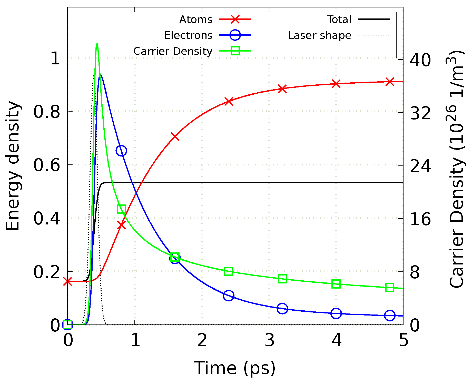
As an example of application of our algorithm to the described system of Equations (7) to (9), we perform the simulations of 800 nm thick silicon target’s response to ultrashort laser pulse irradiation. The parameters of the irradiation are 130 f s duration, 800 n m wavelength, and 0.26 J/cm2 incident fluence. For these conditions, the experimental melting threshold fluence is 0.27 J/cm2 [42], which is in agreement with the result of the nTTM model [43]. The value of fluence is chosen to be just below the melting threshold, providing the applicability of this simple model in the absence of phase transition processes. The sample was divided into 160 cells according to Figure 1. In Figure 2, we show the dynamics of electron–hole carrier density and electronic and atomic energy densities at the silicon surface. The shown energy density is scaled to the melting energy density, which is found to be 3.86 × 10 9 J/m3, according to the simulations. Though Equations (8) and (9) are written in terms of temperature of carriers and atoms, we plotted the corresponding energy densities instead, because their dynamics represents the energy flow between the subsystems and allows plotting the same scale for electrons and atoms, whereas electronic temperature is much higher than the atomic one (see also Figure 2 in [25]). In addition, this choice provides a possibility to show the energy conservation with the total average energy density of the sample (shown with black solid line).
The initial increase in the carrier density followed by the laser pulse is connected to the excitation of new carriers by one- and two-photon absorption processes. With time, the increase changes to the decay due to strong Auger recombination and diffusion processes. The strong peak in the electronic energy density is mostly connected to the free-carrier absorption. Finally, the thermal energy from electron–hole carriers is transferred to the atomic subsystem of the sample leading to gradual increase in the lattice energy density upon the electron–phonon equilibration.

5. Discussion

In case of the explicit scheme, a good guess for the time step requirement can be obtained from the von Neumann stability criterion [20], Δ t ( Δ x ) 2 2 D t h , where D t h is thermal diffusion coefficient, which is proportional to thermal conductivity k e and inversely proportional to the carrier heat capacity C e h . Under initial (prepulse) conditions, in the absence of free carriers, the latter tends to vanish (see Equation (10)), whereas the former is limited (see Table 1). After the laser irradiation starts, a quick increase of T e at initially low n (see also Figure 2 in [25]) leads to an abrupt increase of D t h , which influences the von Neumann stability criterion and limits the maximum possible time step for explicit integration methods. Consequently, if one applies an explicit finite-difference scheme for the numerical solution, the stability of Equation (8) limits the maximum possible time step to 0.5 × 10 19 s for the set of parameters published in [19]. Unfortunately, a mathematical error in [19] did not allow us to directly compare the results (specifically, in Equations (18) and (19) therein).
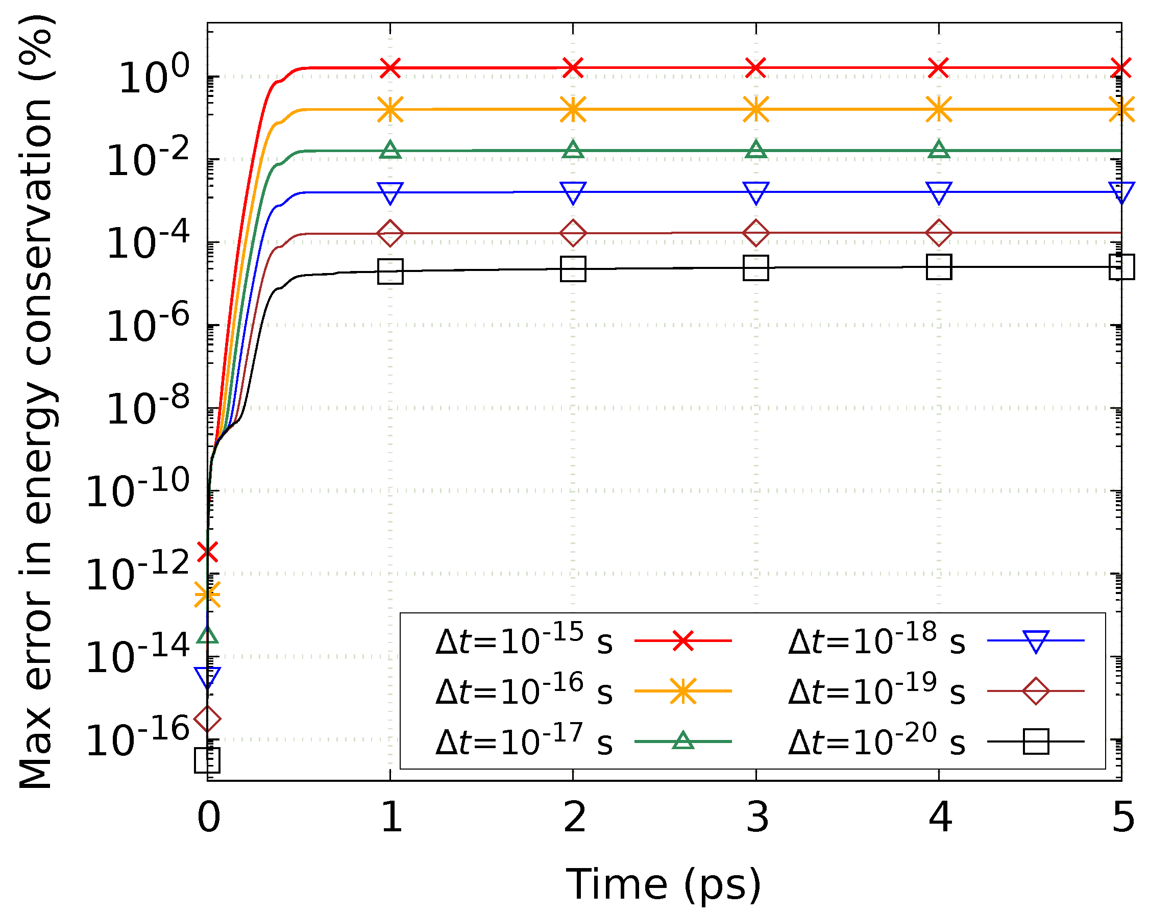
For the numerical setup presented here, according to our test calculations, the explicit scheme requires time steps as small as 1 × 10 24 s , making calculations too expensive. In contrast, the proposed semi-implicit numerical integration scheme provides a stable solution for time step as high as 1 × 10 16 s with the energy conservation about 0.16 % per simulation, Figure 3. At the same time, in case the calculation speed is critical, increasing the time step even higher is possible: 1 × 10 15 s provides the energy conservation within 1.6 %. Thus, the increase in the calculation speed of up to 10 9 times has been achieved, compared with the explicit finite-difference integration scheme.
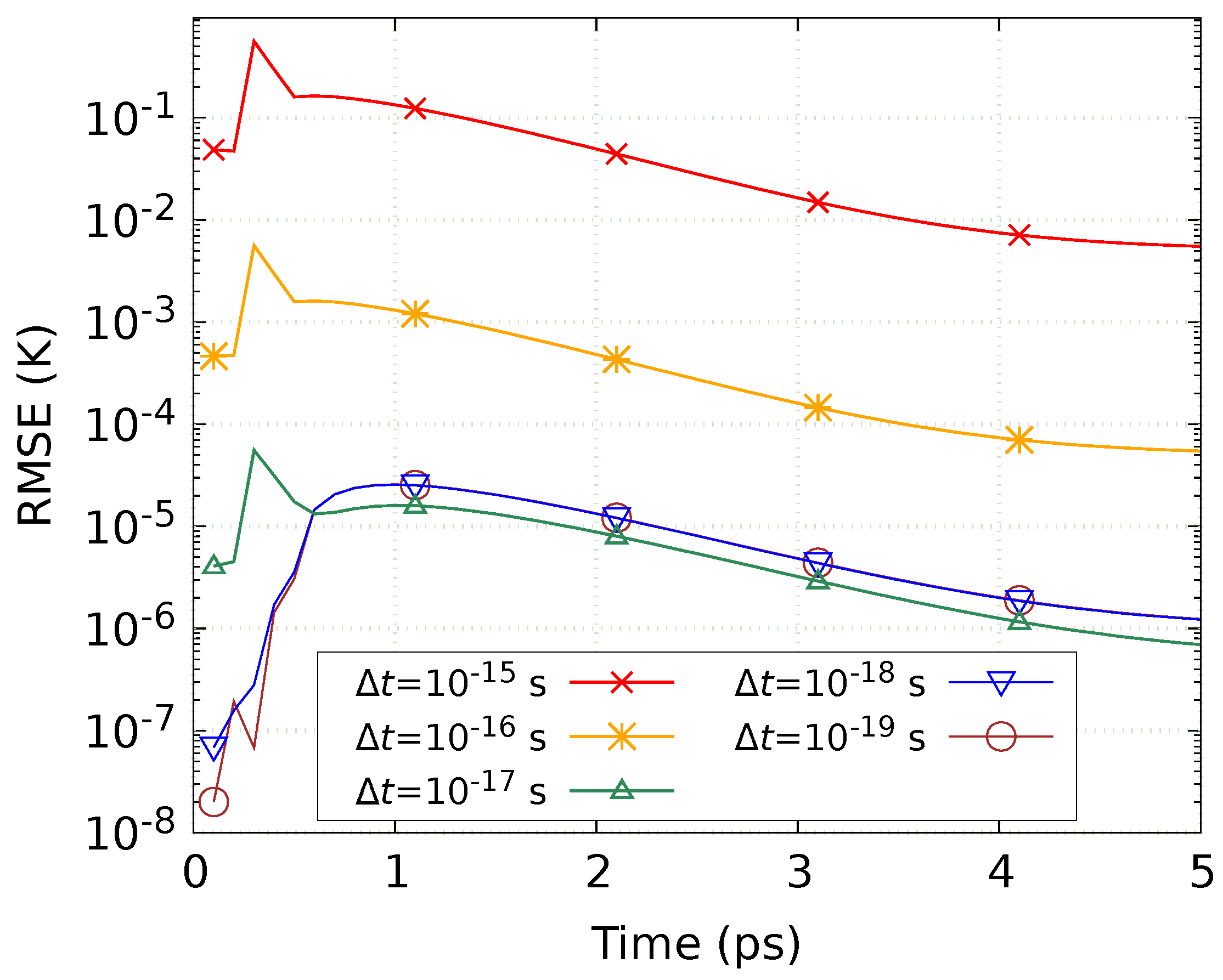
Figure 4 shows the evolution of root mean square error (RMSE) in the electronic temperature for different time steps. The calculation with time step of 1 × 10 20 s was used as a reference. Note that the chosen precision of the predictor–corrector ( 10 6 K) is relatively low and likely influences RMSE at low time steps, preventing further improvement in RMSE for time steps below Δ t = 1 × 10 17 s .
The time step is of course limited by the characteristic times of the involved physical processes, such as laser pulse duration, electron–phonon coupling time, and carrier recombination time. As long as it is much smaller than those mentioned above, the presented integration scheme is tested to be unconditionally stable.
This approach has been successfully applied earlier in order to investigate and improve the presented nTTM model [24]. In [25], we used the described scheme for the solution of the continuum part of the atomistic-continuum model MD-nTTM. The atomistic-continuum model describing the dynamics of gold targets under the ultrashort-pulse lasers also benefited from using the presented approach [23]. The high speed and precision of the scheme allowed to significantly decrease the computational costs of the corresponding simulations. Recently, Rathore et al. utilized the presented finite-difference scheme to simulate temporal evolution of photoinduced thermal strain in InSb [26].
In the mentioned applications, the corresponding system was solved in 1D, based on the assumption of wide laser spot in comparison with the lateral sizes of the computational setup [25]. Whenever it is not the case, one needs to solve the corresponding problem (the vector system of Equations (7) to (9)) in 2D or 3D case. According to the work in [44], the diffusion equation in 3D case can be solved in 3 subsequent steps, each of which involves implicit solution in only one direction (X, Y, or Z) and explicit scheme in the other two directions. In other words, one can use 1D implicit scheme three times: for X, Y, and Z directions separately and consequently. This approach is called alternating direction implicit method (ADI) and is also widely applied for the corresponding 2D problems [45]. Therefore, with appropriate modifications, the presented scheme should be applicable for the considered nonlinear problem in 2D and 3D cases as well.

6. Conclusions

We proposed the semi-implicit integration scheme for the solution of nonlinear diffusion equations or systems of equations containing nonlinear diffusion equations. The scheme is based on the Crank–Nicolson finite-difference integration method, modified with a predictor–corrector algorithm, according to Equation (52). The modification resulted in a possibility to solve nonlinear diffusion equations with high stability and precision. The implemented Fortran source code is available in the Supplementary Materials under the terms of the GNU General Public License version 3 or later.
In the presented example of the scheme application, we reached the speed up of the calculations (by the increase of the integration time step) by up to 10 8 times compared with the explicit scheme, keeping the error in energy conservation below 0.2 %. This error increases linearly with the time step. The algorithm is applicable in case the time step is much smaller than all the characteristic times of the involved physical processes. The existing applications that use the proposed scheme are mentioned and the possible extension for 2D and 3D cases is suggested.

Supplementary Materials

The following are available at https://www.mdpi.com/2076-3417/10/5/1853/s1.

Author Contributions

Conceptualization, D.I.; Data curation, V.L. and D.I.; Formal analysis, V.L. and D.I.; Funding acquisition, B.R., M.G., and D.I.; Investigation, V.L.; Methodology, V.L.; Project administration, B.R., M.G., and D.I.; Resources, B.R. and M.G.; Software, V.L. and D.I.; Supervision, B.R., M.G., and D.I.; Validation, V.L. and D.I.; Visualization, V.L.; Writing—original draft, V.L.; Writing—review & editing, V.L., B.R., M.G., and D.I. All authors have read and agreed to the published version of the manuscript.

Funding

This work was supported by the Deutsche Forschungsgemeinschaft grants IV 122/1-1, IV 122/2, and RE 1141/15-1.

Acknowledgments

The authors acknowledge Markus Nießen for the assistance in the development of the described solution scheme. The work was partly conducted at the Institute for Laser Technology (ILT), RWTH, Aachen, Germany, department of “Nonlinear Dynamics of Laser Processing (NLD)”, in the group of Wolfgang Schulz.

Conflicts of Interest

The authors declare no conflict of interest. The funders had no role in the design of the study; in the collection, analyses, or interpretation of data; in the writing of the manuscript; or in the decision to publish the results.

References

  1. Wu, Z.; Zhao, J.; Yin, J.; Li, H. Nonlinear Diffusion Equations; World Scientific: Singapore, 2001. [Google Scholar]
  2. McKane, A.; Waxman, D. Singular solutions of the diffusion equation of population genetics. J. Theor. Biol. 2007, 247, 849–858. [Google Scholar] [CrossRef] [Green Version]
  3. Bower, J.M.; Bolouri, H. Computational Modeling of Genetic and Biochemical Networks; MIT Press: Cambridge, MA, USA, 2004. [Google Scholar]
  4. Aubert, G.; Kornprobst, P. Mathematical Problems in Image Processing: Partial Differential Equations and the Calculus of Variations; Springer Science & Business Media: New York, NY, USA, 2006; Volume 147. [Google Scholar]
  5. Nagasawa, M. Schrödinger Equations and Diffusion Theory; Springer Science & Business Media: New York, NY, USA, 2012. [Google Scholar]
  6. Bäuerle, D.W. Laser Processing and Chemistry; Springer Science & Business Media: Berlin/Heidelberg, Germany, 2011. [Google Scholar]
  7. Liu, X.; Du, D.; Mourou, G. Laser ablation and micromachining with ultrashort laser pulses. Quantum Electron. IEEE J. 1997, 33, 1706–1716. [Google Scholar] [CrossRef]
  8. Chichkov, B.N.; Momma, C.; Nolte, S.; Von Alvensleben, F.; Tünnermann, A. Femtosecond, picosecond and nanosecond laser ablation of solids. Appl. Phys. A 1996, 63, 109–115. [Google Scholar] [CrossRef]
  9. Gattass, R.R.; Mazur, E. Femtosecond laser micromachining in transparent materials. Nat. Photonics 2008, 2, 219–225. [Google Scholar] [CrossRef]
  10. Chou, S.Y.; Keimel, C.; Gu, J. Ultrafast and direct imprint of nanostructures in silicon. Nature 2002, 417, 835–837. [Google Scholar] [CrossRef] [PubMed]
  11. Le Harzic, R.; Dörr, D.; Sauer, D.; Stracke, F.; Zimmermann, H. Generation of high spatial frequency ripples on silicon under ultrashort laser pulses irradiation. Appl. Phys. Lett. 2011, 98, 211905. [Google Scholar] [CrossRef]
  12. Huang, P.H.; Lai, H.Y. Nucleation and propagation of dislocations during nanopore lattice mending by laser annealing: Modified continuum-atomistic modeling. Phys. Rev. B 2008, 77, 125408. [Google Scholar] [CrossRef]
  13. Stratakis, E.; Ranella, A.; Fotakis, C. Biomimetic micro/nanostructured functional surfaces for microfluidic and tissue engineering applications. Biomicrofluidics 2011, 5, 013411. [Google Scholar] [CrossRef] [Green Version]
  14. Mathis, A.; Courvoisier, F.; Froehly, L.; Furfaro, L.; Jacquot, M.; Lacourt, P.A.; Dudley, J.M. Micromachining along a curve: Femtosecond laser micromachining of curved profiles in diamond and silicon using accelerating beams. Appl. Phys. Lett. 2012, 101, 071110. [Google Scholar] [CrossRef] [Green Version]
  15. Bhuyan, M.K.; Courvoisier, F.; Lacourt, P.A.; Jacquot, M.; Salut, R.; Furfaro, L.; Dudley, J.M. High aspect ratio nanochannel machining using single shot femtosecond Bessel beams. Appl. Phys. Lett. 2010, 97, 081102. [Google Scholar] [CrossRef]
  16. Anisimov, S.I.; Kapeliovich, B.L.; Perel’Man, T.L. Electron emission from metal surfaces exposed to ultrashort laser pulses. Zh. Eksp. Teor. Fiz 1974, 66, 375–377. [Google Scholar]
  17. Van Driel, H.M. Kinetics of high-density plasmas generated in Si by 1.06-and 0.53-mkm picosecond laser pulses. Phys. Rev. B 1987, 35, 8166. [Google Scholar] [CrossRef]
  18. Ivanov, D.S.; Zhigilei, L.V. Combined atomistic-continuum modeling of short-pulse laser melting and disintegration of metal films. Phys. Rev. B 2003, 68, 064114. [Google Scholar] [CrossRef] [Green Version]
  19. Chen, J.K.; Tzou, D.Y.; Beraun, J.E. Numerical investigation of ultrashort laser damage in semiconductors. Int. J. Heat Mass Transf. 2005, 48, 501–509. [Google Scholar] [CrossRef]
  20. Isaacson, E.; Keller, H.B. Analysis of Numerical Methods; Dover Publications: New York, NY, USA, 2012. [Google Scholar]
  21. Crank, J.; Nicolson, P. A practical method for numerical evaluation of solutions of partial differential equations of the heat-conduction type. Math. Proc. Camb. Philos. Soc. 1947, 43, 50–67. [Google Scholar] [CrossRef]
  22. Cebeci, T. Convective Heat Transfer; Springer: Berlin/Heidelberg, Germany, 2002; Volume 1. [Google Scholar]
  23. Ivanov, D.; Lipp, V.; Veiko, V.; Yakovlev, E.; Rethfeld, B.; Garcia, M. Molecular dynamics study of the short laser pulse ablation: Quality and efficiency in production. Appl. Phys. A 2014, 117, 2133–2141. [Google Scholar] [CrossRef]
  24. Rämer, A.; Osmani, O.; Rethfeld, B. Laser damage in silicon: Energy absorption, relaxation, and transport. J. Appl. Phys. 2014, 116, 053508. [Google Scholar] [CrossRef] [Green Version]
  25. Lipp, V.P.; Rethfeld, B.; Garcia, M.E.; Ivanov, D.S. Atomistic-continuum modeling of short laser pulse melting of Si targets. Phys. Rev. B 2014, 90, 245306. [Google Scholar] [CrossRef] [Green Version]
  26. Rathore, R.; Singhal, H.; Chakera, J. Temporal evolution of photoinduced thermal strain in InSb probed by ultra-short laser produced Cu Kα x-rays. J. Appl. Phys. 2019, 126, 105706. [Google Scholar] [CrossRef]
  27. Young, J.F.; Van Driel, H. Ambipolar diffusion of high-density electrons and holes in Ge, Si, and GaAs: Many-body effects. Phys. Rev. B 1982, 26, 2147. [Google Scholar] [CrossRef]
  28. Lietoila, A.; Gibbons, J.F. Computer modeling of the temperature rise and carrier concentration induced in silicon by nanosecond laser pulses. J. Appl. Phys. 1982, 53, 3207–3213. [Google Scholar] [CrossRef]
  29. Sproul, A.B.; Green, M.A. Improved value for the silicon intrinsic carrier concentration from 275 to 375 K. J. Appl. Phys. 1991, 70, 846–854. [Google Scholar] [CrossRef]
  30. Wood, R.F.; Giles, G.E. Macroscopic theory of pulsed-laser annealing. I. Thermal transport and melting. Phys. Rev. B 1981, 23, 2923. [Google Scholar] [CrossRef]
  31. Agassi, D. Phenomenological model for pisosecond-pulse laser annealing of semiconductors. J. Appl. Phys. 1984, 55, 4376–4383. [Google Scholar] [CrossRef]
  32. Thurmond, C.D. The standard thermodynamic functions for the formation of electrons and holes in Ge, Si, GaAs, and GaP. J. Electrochem. Soc. 1975, 122, 1133–1141. [Google Scholar] [CrossRef]
  33. Vankemmel, R.; Schoenmaker, W.; De Meyer, K. A unified wide temperature range model for the energy gap, the effective carrier mass and intrinsic concentration in silicon. Solid-State Electron. 1993, 36, 1379–1384. [Google Scholar] [CrossRef]
  34. Jellison, G.E., Jr.; Modine, F.A. Optical absorption of silicon between 1.6 and 4.7 eV at elevated temperatures. Appl. Phys. Lett. 1982, 41, 180–182. [Google Scholar] [CrossRef]
  35. Jellison, G.E., Jr.; Modine, F.A. Optical functions of silicon between 1.7 and 4.7 eV at elevated temperatures. Phys. Rev. B 1983, 27, 7466. [Google Scholar] [CrossRef]
  36. Dziewior, J.; Schmid, W. Auger coefficients for highly doped and highly excited silicon. Appl. Phys. Lett. 1977, 31, 346–348. [Google Scholar] [CrossRef]
  37. Geist, J.; Gladden, W.K. Transition rate for impact ionization in the approximation of a parabolic band structure. Phys. Rev. B 1983, 27, 4833. [Google Scholar] [CrossRef]
  38. Meyer, J.R.; Kruer, M.R.; Bartoli, F.J. Optical heating in semiconductors: Laser damage in Ge, Si, InSb, and GaAs. J. Appl. Phys. 1980, 51, 5513–5522. [Google Scholar] [CrossRef]
  39. Ioffe Physical-Technical Institute. Electronic Archive “New Semiconductor Materials. Characteristics and Properties”; Silicon Properties. Available online: http://www.ioffe.rssi.ru/SVA/NSM/Semicond/Si/ (accessed on 10 November 2019).
  40. Free Software Foundation. The GNU Scientific Library (gsl-1.15). Available online: https://www.gnu.org/software/gsl (accessed on 10 November 2019).
  41. Thomas, L. Elliptic Problems in Linear Differential Equations over a Network: Watson Scientific Computing Laboratory; Columbia Univ.: Columbia, NY, USA, 1949. [Google Scholar]
  42. Bonse, J.; Brzezinka, K.W.; Meixner, A.J. Modifying single-crystalline silicon by femtosecond laser pulses: An analysis by micro Raman spectroscopy, scanning laser microscopy and atomic force microscopy. Appl. Surf. Sci. 2004, 221, 215–230. [Google Scholar] [CrossRef]
  43. Lipp, V.P. Atomistic-Continuum Modeling of Ultrafast Laser-Induced Melting of Silicon Targets. Ph.D. Thesis, University of Kassel, Kassel, Germany, 2015. [Google Scholar]
  44. Wang, T.Y.; Lee, Y.M.; Chen, C.C.P. 3D thermal-ADI: An efficient chip-level transient thermal simulator. In Proceedings of the 2003 International Symposium on Physical Design, Monterey, CA, USA, 6–9 April 2003; ACM: New York, NY, USA, 2003; pp. 10–17. [Google Scholar]
  45. Peaceman, D.W.; Rachford, H.H., Jr. The numerical solution of parabolic and elliptic differential equations. J. Soc. Ind. Appl. Math. 1955, 3, 28–41. [Google Scholar] [CrossRef]
Figure 1. The finite-difference grid mesh for the solution of the nTTM model equations. Symbol “•” indicates the grid points for n, T e , T a , and E g ( i = 1 , 2 , , N ); symbol “×” indicates the grid points for J , W , D, and k a T a z ( j = 1 , 2 , , N + 1 ).
Applsci 10 01853 g001
Figure 2. Electron/lattice energy densities (divided by the melting energy density) and carrier density dynamics, according to the nTTM model, at the surface of silicon target of 800 nm width, followed by the 130 f s laser pulse at the incident fluence of 0 . 26 J/cm2. The total energy density, averaged through the whole sample, is shown with black solid line. The laser pulse shape, shown with black dotted line, is not in scale.
Applsci 10 01853 g002
Figure 3. Maximal relative error in energy conservation as a function of simulation time for six different time steps. The quantity is calculated from the difference between total absorbed fluence and the total energy in the system.
Applsci 10 01853 g003
Figure 4. Root mean square error in electronic temperature depending on time for different time steps. The calculation with time step of 1 × 10 20 s was used as a reference.
Applsci 10 01853 g004
Table 1. Model parameters.
Parameter NameValueCitation
Initial carrier density n 0 = 1 × 10 16 m 3 [29]
Initial lattice and
carrier temperature
T 0 = 300 K
Lattice specific heat C a = 1.978 × 10 6 + 3.54 × 10 2 T a 3.68 × 10 6 / T a 2 ,   J / ( m 3 K )
( T a in K)
[30]
Lattice thermal
conductivity
k a = 1.585 × 10 5 × T a 1.23 , W/(m · K) ( T a in K)[30]
Carrier thermal
conductivity
k e = k h = 3.47 × 10 18 + 4.45 × 10 16 T e , eV/(s m K)[31]
Indirect band gap E g = 1.170 4.73 × 10 4 T a 2 / ( T a + 636 ) 1.5 × 10 10 n 1 / 3
if 1.170 4.73 × 10 4 T a 2 / ( T a + 636 ) 1.5 × 10 10 n 1 / 3 0
and 0 otherwise, eV ( T a in K, n in m 3 )
[32]
[33]
Interband absorption
(taken from 694 n m laser)
α = 1.34 × 10 5 exp T a / 427 , m 1 [34]
Two-photon absorption β = 15 cm/GW[25]
Reflectivity R = 0.329 + 5 × 10 5 ( T a 300 ) ( T a in K)[35]
Auger recombination
coefficient
γ = 3.8 × 10 43 , m 6 /s[36]
Impact ionization
coefficient
δ = 3.6 × 10 10 exp 1.5 E g / k B T e , s 1 [37]
Free-carrier absorption
cross section
Θ = 2.91 × 10 22 T a / 300 , m 2 ( T a in K)[38]
Electron-phonon
relaxation time
τ e p = 0.5 × 10 12 1 + n / ( 2 × 10 27 ) , s (n in m 3 )[31]
Electron effective mass m e * = 0.36 m e [39]
Hole effective mass m h * = 0.81 m e [39]
Mobility of electrons
(taken at 1000 K)
μ e = 0.0085 m2/V · s[38]
Mobility of holes
(taken at 1000 K)
μ h = 0.0019 m2/V · s[38]