Abstract
In microgrids, paralleled converters can increase the system capacity and conversion efficiency but also generate zero-sequence circulating current, which will distort the AC-side current and increase power losses. Studies have shown that, for two paralleled three-phase voltage-source pulse width modulation (PWM) converters with common DC bus controlled by space vector PWM, the zero-sequence circulating current is mainly related to the difference of the zero-sequence duty ratio between the converters. Therefore, based on the traditional control ideal of zero-vector action time adjustment, this paper proposes a zero-sequence circulating current suppression strategy using proportional–integral quasi-resonant control and feedforward compensation control. Firstly, the dual-loop decoupled control was utilized in a single converter. Then, in order to reduce the amplitude and main harmonic components of the circulating current, a zero-vector duty ratio adjusting factor was initially generated by a proportional–integral quasi-resonant controller. Finally, to eliminate the difference of zero-sequence duty ratio between the converters, the adjusting factor was corrected by a feedforward compensation link. The simulation mode of Matlab/Simulink was constructed for the paralleled converters based on the proposed control strategy. The results verify that this strategy can effectively suppress the zero-sequence circulating current and improve power quality.
1. Introduction
With the wide application of distributed generations (DGs), such as photovoltaic and wind turbines in microgrids, power electronic technology has also rapidly developed [1,2,3]. Among them, the three-phase voltage-source pulse width modulation (PWM) converter has the advantages of high efficiency, low harmonics, simple topology, adjustable power factor, and various control methods. It is mainly used as the interface connected between the DG and the bus or the AC bus and the DC bus [4,5]. However, because the transmission efficiency of a single converter is constrained by semiconductor devices, switching frequencies, and other conditions, it cannot meet the actual demand of power conversion. To solve this problem, the modular parallel operation of converters has been applied in conditions of low voltage and high current [6].
The parallel operation of the power module can increase the system capacity and conversion efficiency as well as improve the stability and reliability of the grid [7,8,9]. However, due to the different hardware parameters between the parallel converters, their switching action cannot be fully synchronized, which will generate zero-sequence voltage. The voltage soon acts on the equivalent resistance between the converters to generate zero-sequence circulating current (ZSCC) [10]. The circulating current will increase the switching loss, reduce the efficiency of the system, increase the probability of converter failure and shutdown, and even destroy the whole system [11,12].
In order to further solve the problem of circulating current in parallel systems, scholars in China and abroad have put forward some active methods. Walker utilized a voltage source converter consisting of gate turn-off thyristors (GTOs) to connect the energy storage system to the AC bus [13]. In this converter, the active and reactive power can be managed independently and quickly by controlling the on/off of the current. Zhang et al. explained that the reason there is a path for ZSCC in the three-phase converter parallel system shown in some studies is because they ignore the magnetic couples caused by the three-pole reactors and the three-pole transformers [14]. Therefore, it is obvious that the addition of three-pole reactors and transformers at the output of the three-phase converter can block this path, which effectively suppresses the ZSCC. Borrega et al. designed a photovoltaic inverter that connects multiple parallel converters to inductors and transformers to reduce the zero-sequence voltage [15]. Bede et al. showed that adding a coupled inductor to the output of paralleled converters can reduce the circulating current. However, the authors also noted that the system is sensitive to low-order harmonics, and adopting proportional resonance (PR) control to improve the scheme can therefore result in better performance [16]. All the above methods take the measure of hardware isolation to block the current path to eliminate the circulating current. Although it is simple and easy, it requires the connection of additional hardware, which will increase the weight, volume, and cost of the system and reduce the system efficiency. Therefore, more and more modulation and control strategies have been proposed. Chen indicated that the zero-sequence problem is mostly caused by zero-sequence low-frequency harmonics. He therefore proposed a ZSCC control method based on harmonic elimination pulse width modulation (HEPWM) [17]. Similarly, a new selective harmonic elimination pulse width modulation (SHE-PWM) control technique was developed by Narimani and Moschopoulos, which can eliminate the ZSCC generated by paralleled modular voltage-source inverters (MVSIs) [18]. Although these modulation methods can reduce low-frequency and high-frequency circulating current, the high switching frequency will increase the switching loss and limit conversion efficiency. Hou put forward a multicarrier PWM technique for parallel three-phase active front-end converters (AFECs) [19]. Without using zero vectors to reduce the circulating current, this modulation synchronizes the output voltage of the converter by carrier phase shifting; however, this is so complex that it is not easy to realize. After analyzing the production principle of ZSCC, Ye et al. proposed a method to suppress it using a proportional–integral (PI) controller to regulate the zero-vector action time in a space vector pulse width modulation (SVPWM) controller [20]. This control scheme is simple to implement, but the PI technique is susceptible to different operating conditions [21]. Zhang et al. used a deadbeat controller instead of a PI controller, which further verified the correctness of the zero-vector action time adjustment method [22]. Zhang et al. improved the traditional PI control method by adding zero-vector feedforward to SVPWM control [23]. Li et al. divided the ZSCC into a small number of high-frequency components and a large number of low-frequency components. The high-frequency components were suppressed by a dual-carrier SVPWM, and a variety of low-frequency harmonics were controlled by a PR controller [24].
In view of the above analysis, this paper examines the ZSCC of two paralleled three-phase full-bridge voltage-source PWM converters with common DC bus and proposes a strategy to suppress ZSCC based on proportional–integral quasi-resonant (PIQR) control and feedforward compensation control. Firstly, for a single converter, the dual-loop decoupled control of inner current loop and outer voltage loop was used to generate the reference voltage, and the switching signal was generated by an SVPWM controller. Then, by establishing an equivalent physical model of ZSCC, the causes were analyzed. To reduce the amplitude and main harmonic components of the ZSCC, a zero-vector duty ratio adjusting factor was initially generated by the PIQR controller. Finally, for the purpose of eliminating the effect of the difference of the zero-sequence duty ratio on the system and improving the dynamic response of the zero-sequence current loop, a feedforward compensation controller was added to correct the adjusting factor. The simulation results showed that the proposed method could effectively reduce ZSCC, and its performance was better than the traditional PI control.
The rest of this paper is organized as follows. In Section 2, the voltage–current dual-loop decoupled control strategy of a single PWM converter is presented. Section 3 establishes the mathematical and physical models of paralleled PWM converters and analyzes the generation of ZSCC. The proposed control strategy in parallel systems is introduced in Section 4. Section 5 illustrates the simulation process and presents the results in detail. Section 6 concludes the paper.
2. Dual-Loop Decoupled Control Strategy of PWM Converter
The control of a single converter was the basis for studying the ZSCC problem. The three-phase full-bridge voltage-source PWM converter was used in this study. Its input is three-phase balanced AC current, and the output is DC current. Figure 1 illustrates the main circuit structure of this kind of converter [25], where is the voltage of the AC side, L is the filter inductance at the AC side, is the equivalent resistance of the converter, is the three-phase current at the AC side, is the three bridge arms, is the capacitor at the DC side, is the DC bus voltage, is the load current at the DC side, and is the DC-side resistance.
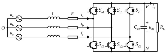
Figure 1.
Structure of three-phase voltage-source pulse width modulation (PWM) converter.
Assuming the negative pole of the DC-side capacitor as the reference point, the mathematical model of a single PWM converter shown in Figure 1 can be expressed as follows:
where is the neutral voltage at the AC side, and represents the output duty ratio of the three-phase bridge arm.
The above mathematical model of a converter in static three-phase coordinates is very intuitive. However, because the voltage and current on the AC side are time-varying AC variables, in order to realize the zero steady-state error control, it is necessary to change the three-phase sinusoidal quantities into DC quantities. At present, the transformation from three-phase static coordinate system ABC to two-phase synchronous rotating coordinate system d-q is mostly realized by three-dimensional coordinate transformation [26]. The d-q type mathematical model of the converter can be derived as follows:
where is the fundamental frequency of three-phase alternating current.
According to Equation (2), in the mathematical model of d-q reference frame, there is a coupling phenomenon between the d-axis component and the q-axis component, which leads to the inability to adjust the active and reactive components, respectively, of the system. Therefore, it is necessary to decouple these coupling terms. In addition, PI control was utilized in this study to achieve the goal of zero steady-state error tracking [27]. Based on these theories, the inner current control loop is as follows:
where and are the proportional and integral coefficients of the current loop PI controller, respectively, and and are the reference currents.
According to the instantaneous reactive power theory, affects the active power of the system, and affects the reactive power of the system. In order to achieve unit power operation, was set to zero in this study. Moreover, to realize the zero steady-state error control of the d-axis reference current, PI control was used to control the outer voltage loop to generate , which can be described as follows:
where and are the proportional and integral coefficients of the voltage loop PI controller, respectively, and is the reference voltage of the DC bus.
SVPWM is a pulse width modulation technique that has been improved by sinusoidal pulse width modulation (SPWM), which is often used for the control of three-phase bridge converters [28]. This modulation represents the eight working states of the three bridge arms with eight voltage space state vectors. The process of space vector composition is shown in Figure 2, where the state vector is the nonzero vector, and and are the zero vectors.
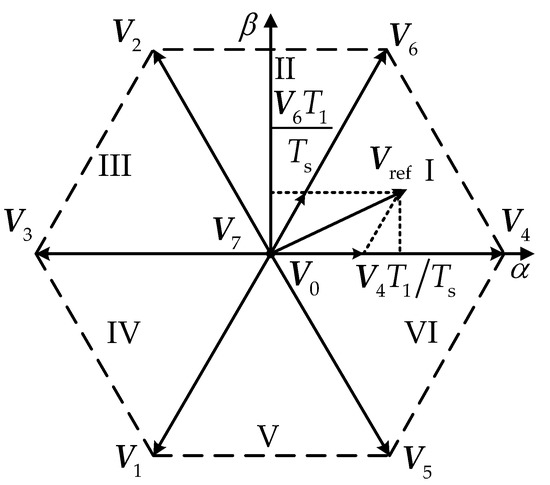
Figure 2.
Principle of space vector composition.
As depicted in Figure 2, the input reference voltage can be represented by two adjacent nonzero state vectors and zero vectors. As the specific working principle and implementation method of SVPWM have been introduced in detail in [29], they will not be repeated here. This modulation technique can not only improve the utilization rate of the voltage but also effectively reduce the switching frequency and improve the reliability of the system [30]. Therefore, in this study, SVPWM was used to control the switching of the converter.
Based on the above analysis, the dual-loop decoupled control strategy of the three-phase voltage-source PWM converter based on PI control and SVPWM control is illustrated in Figure 3.
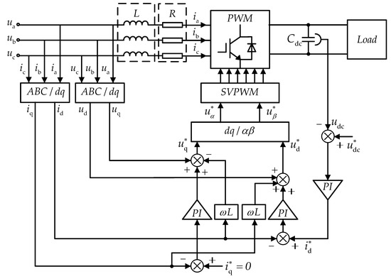
Figure 3.
Control block of three-phase PWM converter.
3. Analysis of ZSCC in Paralleled PWM Converters
The parallel system studied in this work consisted of two three-phase voltage-source PWM converters, as shown in Figure 1, connected to the common DC link, which is depicted in Figure 4.
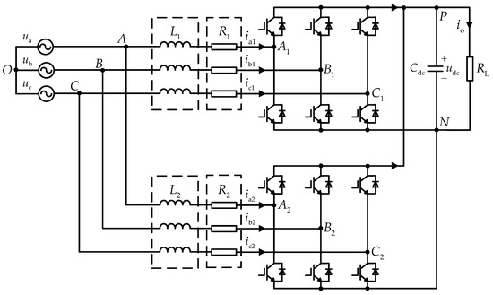
Figure 4.
Topology of two paralleled three-phase voltage-source PWM converters.
From Figure 4 and Equation (1), the average model of the parallel system in static three-phase coordinates can be expressed as follows:
where expressions with subscript “” refer to the related variables of the converter, .
For a single PWM converter, no ZSCC is generated because there is no circulating current path. However, when two converters are connected in parallel, a path will be formed. If a zero-sequence voltage exists, ZSCC will also be generated on the loop impedance. The ZSCC is defined in this study as follows:
where denotes the ZSCC of the module, . The ZSCC of Module 1 and the circulating current of Module 2 are equal in size and in opposite directions.
In the SVPWM control, because the third harmonic is injected, the sum of the output duty ratios of the three-phase bridge arms of the PWM converter will not be equal to zero. The zero-sequence duty ratio of the converter can be defined as follows:
The voltage of the three-phase alternating current was balanced in this study, which means that . Therefore, combining Equations (5)–(7) results in the following:
The equivalent mathematical model of ZSCC can be derived from Equation (8) as follows:
The physical circuital model of Equation (9) is shown in Figure 5, where denotes the zero-sequence voltage of the converter, .
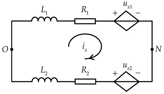
Figure 5.
Equivalent physical model of zero-sequence circulating current (ZSCC) in paralleled converters.
Figure 5 demonstrates that, when analyzing the ZSCC problem, each converter module can be equivalent to a branch in the physical circuit, and two branches can be combined into a circulating current path. It can be seen that the magnitude of ZSCC is related to the AC-side inductance, equivalent resistance, and zero-sequence voltage of the two branches, and controlling the zero-sequence voltage difference to zero is the key to eliminating ZSCC.
4. Control Strategy for Suppressing ZSCC
In this study, each converter in the parallel system adopted the dual-loop decoupled control strategy described in Section 2. Therefore, by synthesizing the key element of the ZSCC suppression shown in Figure 5, the zero-sequence voltage could be adjusted by controlling the zero-sequence duty ratio of the converter. When the zero-sequence duty ratios of the branches are equal, the zero-sequence voltages are equal, and the ZSCC is naturally suppressed. In addition, for two paralleled converters, only the zero-sequence duty ratio of one converter needs to be controlled to suppress the ZSCC of the entire system. Extending to the parallel system with converters, the suppression of ZSCC needs to control the zero-sequence duty ratios of converters.
As noted in Section 2, in space vector modulation, the zero-sequence duty ratio is related to the action time of the state vectors. Among them, two nonzero state vectors can uniquely determine a reference voltage vector under constant action time, and changing the action time of the zero-state vector will not affect the output voltage and current. Therefore, the zero-sequence duty ratio is usually regulated by controlling the zero-vector action time. Taking sector Ι as an example, the switching signal before and after adjustment in SVPWM control are presented in Figure 6, where the duty ratios of two nonzero vectors are and , respectively, and the duty ratio of zero vector is .
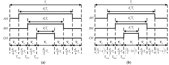
Figure 6.
Switching signals for space vector pulse width modulation (SVPWM) control in sector I: (a) before adjustment; (b) after adjustment.
As shown in Figure 6a, the zero-sequence duty ratio before adjustment can be expressed as follows:
According to Figure 6b, an adjusting factor is added to the duty ratio of zero vector in a PWM period. The action time of and are changed to and , respectively. After adjusting, the zero-sequence duty ratio can be described as follows:
Moreover, Figure 6b shows that adjusting the factor directly changes the switching time , , and of the state vector in SVPWM. The switching time after correcting can be derived as follows:
where should be within the range of , which means that the action time of the zero vector is not less than zero without changing the action time of the nonzero vector.
Substituting Equation (11) into Equation (9) can get the modified ZSCC model, which can be expressed as follows:
where represents the duty ratio of the related vector in the module, and denotes the zero-vector duty ratio adjusting factor of the module, .
In practical engineering, the equivalent resistance value of the converter is much smaller than its reactance value, so the and can be ignored [31]. Moreover, because only one converter is needed to control the entire ZSCC, is set to zero. What is more, the sum of the duty ratio of the two nonzero vectors and the zero vector is 1. Therefore, Equation (13) can be simplified as follows:
where .
In order to analyze the system function generating the ZSCC, the Laplace transform of Equation (14) is obtained as follows:
Therefore, Equation (15) shows that the generating system of ZSCC can be regarded as a first-order system with disturbance. In this system, the input is the adjusting factor, and the output is the ZSCC. For the first-order system, PI control is generally used. The input of the PI controller here is the difference between the actual value and the reference value of ZSCC, and the output is the adjusting factor. However, as shown in [32], the main low-frequency harmonics in ZSCC are the 3rd, 9th, and 15th. Hence, to suppress these harmonics, the resonant controller needs to be added to the PI control.
As the gain of an ideal resonant controller at the resonant frequency is infinite, which cannot be achieved in practice, the quasi-resonant controller is currently used the most [33]. This kind of controller can increase system bandwidth, suppress higher harmonics, and is easy to implement. In this study, a PI controller with quasi-resonant control (PIQR) was used. Its system function can be expressed as follows:
where and are the proportional and integral coefficients of the ZSCC control loop, respectively, is the resonance coefficient for suppressing the harmonic, is the cut-off angular frequency, and is the fundamental angular frequency of the AC-side voltage.
According to Equation (16), the generation of zero-vector duty ratio adjusting factor can be derived as follows:
where the ZSCC reference value is set to zero.
Due to the differences in line parameters, the currents on the branches of different converters are unequal, so the reference voltages generated by the current regulators are also different, which means nonzero vector duty ratio differences are bound to occur. It can be seen from Equation (15) that this difference will have a certain effect on the adjusting factor. However, the PIQR controller does not eliminate this disturbance, so this paper proposes a control strategy that combines a feedforward compensation scheme with PIQR. The improved adjusting factor generation can be expressed as follows:
The ZSCC control loop proposed in this paper and obtained according to Equation (18) is shown in Figure 7.
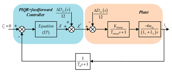
Figure 7.
Control block diagram of suppressing ZSCC in two paralleled converters using the proposed control strategy.
Based on the above analysis, the control strategy of the two parallel converter system is depicted in Figure 8. In this control scheme, the two converters are controlled by an independent voltage–current loop. The difference is that when the switching signal is generated through space vector modulation, the first converter uses the modulation method, as shown in Figure 6a, while the second converter needs to use the modulation method after adding the zero-vector adjusting factor, as shown in Figure 6b. First of all, the three-phase current on the first converter line is collected, and the ZSCC is calculated. Then, through the PIQR controller, zero-vector duty ratio adjusting factor is initially generated, and the 3rd, 9th, and 15th harmonics in the ZSCC are suppressed. Afterwards, the duty ratio of the nonzero vector in the SVPWM controller of the two converters is collected, and the disturbance variable is calculated. After multiplying the disturbance by the coefficient, it is used as the feedforward compensation regulating factor. Finally, the switching signal of the second converter is modified by this regulating factor.
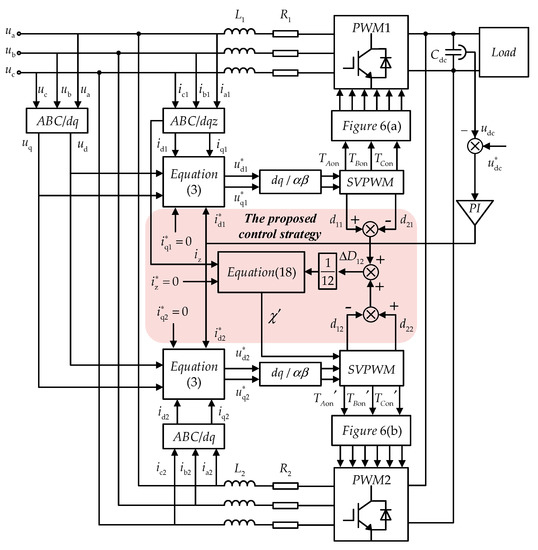
Figure 8.
Control system block diagram of paralleled converters.
5. Simulation and Analysis
In order to observe the rectification effect of the dual-loop decoupled control and verify the effectiveness of the proposed control strategy to suppress ZSCC, the parallel converter system shown in Figure 4 was performed on the MATLAB/Simulink R2016b platform, and three sets of simulation experiments were performed. The sampling period of the simulation platform was 10−6 s, and other simulation parameters of the parallel system are shown in Table 1.

Table 1.
Parameters for simulation of paralleled system.
From Table 1, it can be seen that in order to ensure that the AC-side line parameter difference is the only variable to study the circulating system, the other control parameters of the two converters in the system were kept completely equal, including the proportional and integral coefficient of the voltage–current loop, the switching period of the SVPWM controller, and so on.
5.1. Case 1
The control target of the converter was input current and output voltage, so it was necessary to verify the power conversion ability of the parallel converter. In this case, the filter inductance of the AC side was equal, and there was no ZSCC suppression measure. Here, , and other parameters were the same as those listed in Table 1. The experimental results of 0.3–0.6 s are presented in Figure 9.
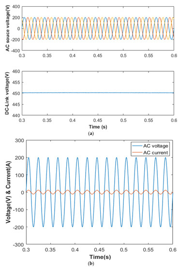
Figure 9.
Simulation waveforms in parallel system with equal inductance and without ZSCC suppression strategy: (a) waveform of rectification (input, three-phase AC-source voltage; output, DC voltage); (b) A-phase voltage and current waveform of converter 1.
As shown in Figure 9a, the peak value of the three-phase AC voltage source was 200 V. Through the converter, the output voltage could reach the rated voltage of 450 V and remain stable. In addition, as can be seen in Figure 9b, the phase of the input voltage and input current of the converter were basically the same, and the power factor angle was close to zero, indicating that the reactive power could be effectively suppressed.
5.2. Case 2
Theoretically, if the circuit parameters of two branches are identical, the switch of the PWM converter will be synchronized, so the zero-sequence duty ratio difference of the two converters will be zero. According to Equation (9), there will be no ZSCC in the system. In this case, the filter inductance of the AC side was equal, and the proposed control strategy was utilized, where and other parameters are same as those listed in Table 1. The parameters of the control strategy proposed in this paper are proportional coefficient , integral coefficient , resonance coefficient of the 3rd harmonic , resonance coefficient of the 9th harmonic , resonance coefficient of the 15th harmonic , and cut-off angular frequency rad/s. The ZSCC waveforms are shown in Figure 10.
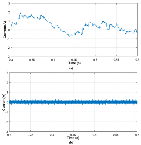
Figure 10.
ZSCC of parallel system in equal inductance condition: (a) without any ZSCC suppression strategy; (b) with the proposed ZSCC suppression strategy.
Figure 10a demonstrates that there was still a ZSCC in this case. However, the amplitude was small, and the peak-to-peak value between 0.3 and 0.6 s was 2.75 A. Therefore, it was impossible to make the switching time of the two converters exactly the same. As shown in Figure 10b, when the control strategy was added to the parallel system, the effect of reducing the ZSCC amplitude was obvious. The peak-to-peak value of ZSCC was 0.6 A. Compared with no control strategy, the ZSCC amplitude was reduced by 78%, which means that the control strategy proposed in this paper could effectively suppress ZSCC in this case.
5.3. Case 3
In practical engineering, the line parameters of the two branches are not exactly the same, so it is necessary to focus on the study of ZSCC when the filter inductance of the AC side is not equal. In this case, and . The ZSCC and the harmonics it contains are shown in Figure 11.
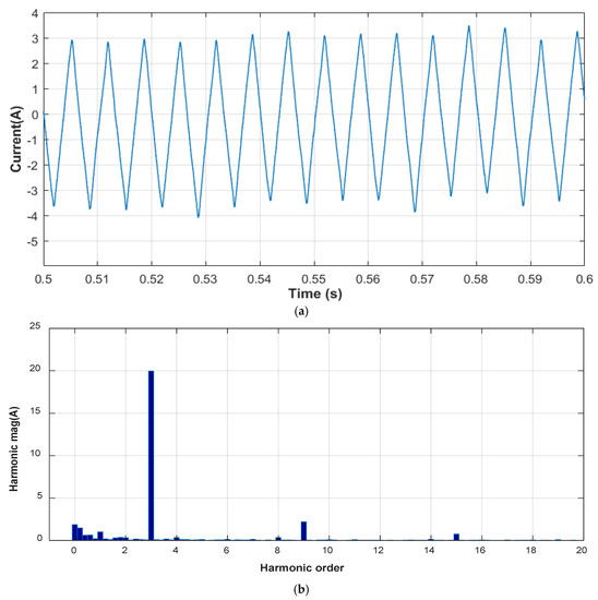
Figure 11.
Simulation waveforms in parallel system with unequal inductance and without ZSCC suppression strategy: (a) ZSCC of system; (b) harmonics contained in ZSCC.
It can be seen from Figure 11a that when the difference of inductance in the line increased, the ZSCC amplitude also increased, and the peak-to-peak value between 0.5 and 0.6 s was 7.6 A. Figure 11b is the spectrum of the ZSCC from 0.5 to 0.6 s after fast Fourier transform (FFT) with 50 Hz as the fundamental frequency. The following simulation adopted the same harmonic analysis method. According to Figure 11b, there were low harmonic components in the ZSCC without any measures, with the 3rd, 9th, and 15th harmonics the more prominent. Therefore, it is necessary to take measures to reduce the ZSCC amplitude and suppress low-frequency harmonic components.
The traditional PI control strategy is a common control method to suppress ZSCC, as noted in Section 1. Therefore, in order to compare the traditional control strategy and the PI control strategy proposed in this paper, the PI control strategy was first applied to control the ZSCC, and the experimental results were analyzed. The proportional coefficient and integral coefficient of the PI controller were set as 0.02 and 10, respectively. The simulation result is presented in Figure 12.
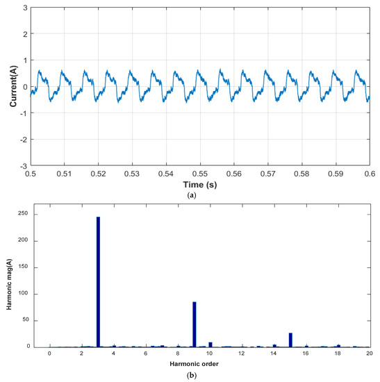
Figure 12.
Simulation waveforms in parallel system with unequal inductance and with traditional proportional–integral (PI) suppression strategy: (a) ZSCC of system; (b) harmonics contained in ZSCC.
As shown in Figure 12a, under the same conditions, the traditional PI suppression strategy could reduce the ZSCC to a certain extent, and the peak-to-peak value was 1.32 A. Compared with no control strategy, the ZSCC amplitude was reduced by 82.6%. However, according to Figure 12b, the PI strategy had no suppression effect on the harmonics in the ZSCC, and the amplitude of the low-frequency harmonics increased. These results show that the traditional PI suppression strategy is insufficient in suppressing ZSCC.
Theoretically, the control strategy proposed in this paper can reduce the ZSCC amplitude and also suppress the low-frequency harmonic components. Therefore, in order to verify its effectiveness, the control strategy proposed in this paper was added to the parallel system, and the simulation results of the ZSCC were observed and analyzed. For parameter setting, in order to maintain consistency with the above PI controller, the proportional and integral coefficients of the PIQR controller were the same as those of the PI controller. The other parameters were , , , rad/s. The simulation result is shown in Figure 13.
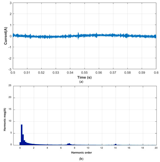
Figure 13.
Simulation waveforms in parallel system with unequal inductance and with the proposed suppression strategy: (a) ZSCC of system; (b) harmonics contained in ZSCC.
Figure 13a shows that the control strategy proposed in this paper could greatly reduce the ZSCC, and the peak-to-peak value was 0.63 A. The ZSCC amplitude with the proposed control strategy was 91.7% less than that without any control measures and 52.27% less than that with the traditional PI control strategy. As can be seen from Figure 13b, the proposed strategy could effectively suppress the specified harmonic components, while the influence on other harmonic components was small. In addition, the total harmonic distortion (THD) analysis of A-phase current on the AC side of Module 1 was carried out. The THD without the control strategy was 9.21%, the THD with the PI control algorithm was 4.40%, and the THD with the control strategy proposed in this paper was 4.23%.
According to the analysis of the above three cases, the control strategy proposed in this paper for the parallel operation of two converters could not only guarantee the output power quality but also effectively suppress the circulating current amplitude, reduce low-frequency harmonics, and improve input power quality when there is a ZSCC between the converters. Furthermore, compared to experimental results of the traditional PI control scheme, the proposed strategy performed better than traditional algorithms.
6. Conclusions
In order to solve the problem of ZSCC in paralleled converters, based on the traditional ZSCC control ideal of zero-vector action time adjustment, this paper proposes an improved ZSCC control strategy based on PIQR control and feedforward compensation control. Although the traditional PI control scheme can suppress the ZSCC amplitude to a certain extent, it cannot eliminate the low-frequency harmonic components with large amplitude. Therefore, a quasi-resonant controller was used to suppress the harmonic. Moreover, to eliminate the influence of the nonzero vector duty ratio between the converters on the zero-vector adjusting factor, a feedforward compensation link was added to the end of the PIQR controller. The experimental results show that the proposed control strategy is simple to implement, and compared with the PI control strategy, it can more effectively suppress the ZSCC amplitude, reduce low-frequency harmonics, and improve power quality.
In future work, we will do significant research on the following aspects. First, we will improve the control strategy proposed in this paper and apply it to a system with converters in parallel. Second, we will consider the control of ZSCC when the load on the DC side changes and conduct in-depth research.
Author Contributions
Conceptualization, Z.H.; methodology, Z.H.; software, Z.H.; validation, X.W. and B.J.; formal analysis, Z.H. and J.C.; investigation, Z.H. and J.C.; resources, B.J.; data curation, Z.H.; writing—original draft preparation, Z.H.; writing—review and editing, X.W.; visualization, Z.H.; supervision, B.J.; project administration, X.W. and B.J. All authors have read and agreed to the published version of the manuscript.
Funding
This research received no external funding.
Acknowledgments
We gratefully acknowledge the technical assistance of DL850E ScopeCorder.
Conflicts of Interest
The authors declare no conflict of interest.
References
- Li, X.L.; Guo, L.; Li, Y.W.; Guo, Z.; Hong, C.; Zhang, Y.; Wang, C.S. A Unified Control for the DC–AC Interlinking Converters in Hybrid AC/DC Microgrids. IEEE Trans. Smart Grid 2018, 9, 6540–6553. [Google Scholar] [CrossRef]
- Xiao, H.G.; Luo, A.; Shuai, Z.K.; Jin, G.B.; Huang, Y. An Improved Control Method for Multiple Bidirectional Power Converters in Hybrid AC/DC Microgrid. IEEE Trans. Smart Grid 2016, 7, 340–347. [Google Scholar] [CrossRef]
- Radwan, E.; Nour, M.; Awada, E.; Baniyounes, A. Fuzzy Logic Control for Low-Voltage Ride-Through Single-Phase Grid-Connected PV Inverter. Energies 2019, 12, 4796. [Google Scholar] [CrossRef]
- Loh, P.C.; Li, D.; Chai, Y.K.; Blaabjerg, F. Autonomous Control of Interlinking Converter With Energy Storage in Hybrid AC–DC Microgrid. IEEE Trans. Ind. Appl. 2013, 49, 1374–1382. [Google Scholar] [CrossRef]
- Karanayil, B.; Agelidis, V.G.; Pou, J. Performance Evaluation of Three-Phase Grid-Connected Photovoltaic Inverters Using Electrolytic or Polypropylene Film Capacitors. IEEE Trans. Sustain. Energy 2014, 5, 1297–1306. [Google Scholar] [CrossRef]
- Yang, P.C.; Xia, Y.H.; Yu, M.; Wei, W.; Peng, Y.G. A Decentralized Coordination Control Method for Parallel Bidirectional Power Converters in a Hybrid AC–DC Microgrid. IEEE Trans. Ind. Electron. 2018, 65, 6217–6228. [Google Scholar] [CrossRef]
- Liu, Z.; Liu, J.J.; Hou, X.Y.; Dou, Q.Y.; Xue, D.H.; Liu, T. Output Impedance Modeling and Stability Prediction of Three-Phase Paralleled Inverters with Master-Slave Sharing Scheme Based on Terminal Characteristics of Individual Inverters. IEEE Trans. Power Electron. 2016, 31, 5306–5320. [Google Scholar] [CrossRef]
- Hoang, T.T.G.; Wang, X.H.; Zhou, X.Z.; Tian, L.F.; Chen, W.C. Fractional proportional integral controller applied into two parallel 3-phase PWM rectifiers. In Proceedings of the 2017 IEEE 2nd Advanced Information Technology, Electronic and Automation Control Conference (IAEAC), Chongqing, China, 25–26 March 2017; pp. 9–13. [Google Scholar]
- Pan, C.T.; Liao, Y.H. Modeling and Coordinate Control of Circulating Currents in Parallel Three-Phase Boost Rectifiers. IEEE Trans. Ind. Electron. 2007, 54, 825–838. [Google Scholar] [CrossRef]
- Xiao, H.G.; Luo, A.; Wang, Y.C.; Tu, C.M.; Shuai, Z.K. A Circulating Current Control Method for Paralleled Inverters in Microgrids. Zhongguo Dianji Gongcheng Xuebao 2014, 34, 3098–3104. (In Chinese) [Google Scholar]
- Pan, C.T.; Liao, Y.H. Modeling and Control of Circulating Currents for Parallel Three-Phase Boost Rectifiers With Different Load Sharing. IEEE Trans. Ind. Electron. 2008, 55, 2776–2785. [Google Scholar]
- Zhu, R.W.; Liserre, M.; Chen, Z.; Wu, X.J. Zero-Sequence Voltage Modulation Strategy for Multiparallel Converters Circulating Current Suppression. IEEE Trans. Ind. Electron. 2017, 64, 1841–1852. [Google Scholar] [CrossRef]
- Walker, L.H. 10-MW GTO Converter for Battery Peaking Service. In Proceedings of the 1988 IEEE Industry Applications Society Annual Meeting, Pittsburgh, PA, USA, 2–7 October 1988; pp. 63–72. [Google Scholar]
- Zhang, Y.; Duan, S.X.; Kang, Y.; Chen, J. Research of Zero-sequence Circulating Currents Between Parallel Three-Phase Inverters. Zhongguo Dianji Gongcheng Xuebao 2006, 26, 62–67. (In Chinese) [Google Scholar]
- Borrega, M.; Marroyo, L.; Gonz´alez, R.; Balda, J.; Agorreta, J.L. Modeling and Control of a Master–Slave PV Inverter With N-Paralleled Inverters and Three-Phase Three-Limb Inductors. IEEE Trans. Power Electron. 2013, 28, 2842–2855. [Google Scholar] [CrossRef]
- Bede, L.; Gohil, G.; Ciobotaru, M.; Kerekes, T.; Teodorescu, R.; Agelidis, V.G. Circulating current controller for parallel interleaved converters using PR controllers. In Proceedings of the IECON 2015 -41st Annual Conference of the IEEE Industrial Electronics Society, Yokohama, Japan, 9–12 November 2015; pp. 3997–4002. [Google Scholar]
- Chen, T.P. Zero-Sequence Circulating Current Reduction Method for Parallel HEPWM Inverters between AC Bus and DC Bus. IEEE Trans. Ind. Electron. 2012, 59, 290–300. [Google Scholar] [CrossRef]
- Narimani, M.; Moschopoulos, G. Three-Phase Multi-Module VSIs Using SHE-PWM with Reduced Zero-Sequence Circulating Current. In Proceedings of the 2012 IEEE Energy Conversion Congress and Exposition (ECCE), Raleigh, NC, USA, 15–20 September 2012; pp. 2859–2865. [Google Scholar]
- Hou, C.C. A Multicarrier PWM for Parallel Three-Phase Active Front-End Converters. IEEE Trans. Power Electron. 2013, 28, 2753–2759. [Google Scholar] [CrossRef]
- Ye, Z.H.; Boroyevich, D.; Choi, J.Y.; Lee, F.C. Control of Circulating Current in Two Parallel Three-Phase Boost Rectifiers. IEEE Trans. Power Electron. 2002, 17, 609–615. [Google Scholar]
- Chen, H.; Xing, X.Y. Circulating Current Analysis and Suppression for Module Grid-Connected Inverters under Unbalanced Conditions. IEEE Access 2018, 6, 69120–69129. [Google Scholar] [CrossRef]
- Zhang, X.G.; Zhang, W.J.; Chen, J.M.; Xu, D.G. Deadbeat Control Strategy of Circulating Currents in Parallel Connection System of Three-Phase PWM Converter. IEEE Trans. Energy Convers. 2014, 29, 406–417. [Google Scholar]
- Zhang, X.G.; Wang, T.Y.; Wang, X.F.; Wang, G.L.; Chen, Z.; Xu, D.G. A Coordinate Control Strategy for Circulating Current Suppression in Multiparalleled Three-Phase Inverters. IEEE Trans. Ind. Electron. 2017, 64, 838–847. [Google Scholar] [CrossRef]
- Li, K.; Xu, H.B.; Ma, Q.; Ma, L.; Xin, X.S. Research on the control of zero-sequence circulating current of paralleled inverters based on Dual-carrier-modulator and PR control. In Proceedings of the 2014 IEEE Conference and Expo Transportation Electrification Asia-Pacific (ITEC Asia-Pacific), Beijing, China, 31 August–3 September 2014; pp. 1–7. [Google Scholar]
- Divya, E.; Gnanavadivel, J. Harmonic Elimination in three phase PWM rectifier using FPGA control. In Proceedings of the 2011 International Conference on Emerging Trends in Electrical and Computer Technology (ICETECT), Nagercoil, India, 23–24 March 2011; pp. 436–441. [Google Scholar]
- Kamran, H.; Shahid, A.K.; Alex, V.D.B.; Qadeer, U.H. Circulating Current Reduction in MMC-HVDC System Using Average Model. Appl. Sci. 2019, 9, 1383. [Google Scholar]
- Tounsi, K.; Djahbar, A.; Barkat, S.; Sanjeevikmar, P.; Atif, I. Extended Kalman Filter Based Sliding Mode Control of Parallel-Connected Two Five-Phase PMSM Drive System. Electronics 2018, 7, 14. [Google Scholar]
- Zhang, X.G.; Li, W.W.; Xiao, Y.; Wang, G.L.; Xu, D.G. Analysis and Suppression of Circulating Current Caused by Carrier Phase Difference in Parallel Voltage Source Inverters With SVPWM. IEEE Trans. Power Electron. 2018, 33, 11007–11020. [Google Scholar]
- Yang, G.J.; Sun, L.; Cui, N.Z.; Lu, Y.P. Study on Method of the Space Vector PWM. Zhongguo Dianji Gongcheng Xuebao 2001, 5, 79–83. (In Chinese) [Google Scholar]
- Chen, G.Q.; Kang, J.L.; Zhao, J.W. Numeric analysis and simulation of space vector pulse width modulation. Adv. Eng. Softw. 2013, 65, 60–65. [Google Scholar] [CrossRef]
- Wang, J.P.; Hu, F.Y.; Jiang, W.D.; Wang, W.; Gao, Y. Investigation of Zero Sequence Circulating Current Suppression for Parallel Three-Phase Grid-Connected Converters Without Communication. IEEE Trans. Ind. Electron. 2018, 65, 7620–7629. [Google Scholar] [CrossRef]
- Li, K.; Zheng, H.; Ma, L.; Han, T.; Liang, Z.F. Zero-sequence Circulating Current Inhibition of Paralleled Inverters Based on Active Zero State PWM and PR Control. Dianli Xitong Zidonghue 2015, 39, 126–131. (In Chinese) [Google Scholar]
- Yang, D.C.; Xu, Z.X.; Li, W.L.; Bu, F.B. Droop control strategy of the AC/DC hybrid micro-grid based on quasi-PR control. J. Eng. 2017, 2017, 2634–2642. [Google Scholar] [CrossRef]
© 2020 by the authors. Licensee MDPI, Basel, Switzerland. This article is an open access article distributed under the terms and conditions of the Creative Commons Attribution (CC BY) license (http://creativecommons.org/licenses/by/4.0/).