Article

Study on the Mechanical Responses of Plastic Pipes Made of High Density Polyethylene (HDPE) in Water Supply Network

by
Sorin Vlase
1,2,
Marin Marin
3,
Maria Luminița Scutaru
1,*,
Dumitru Daniel Scărlătescu
4 and
Carol Csatlos
5
1
Department of Mechanical Engineering, Transilvania University of Brașov, 500036 Brașov, Romania
2
Romanian Academy of Technical Sciences, 100230 Bucharest, Romania
3
Department of Mathematics, Transilvania University of Brașov, 500036 Brașov, Romania
4
Water Company, 500036 Brașov, Romania
5
Faculty of Food and Tourism, Transilvania University of Brașov, 500036 Brașov, Romania
*
Author to whom correspondence should be addressed.
Appl. Sci. 2020, 10(5), 1658; https://doi.org/10.3390/app10051658
Submission received: 8 January 2020 / Revised: 22 February 2020 / Accepted: 25 February 2020 / Published: 1 March 2020
(This article belongs to the Section Civil Engineering)

Abstract

:

Featured Application

The research results have direct practical applicability. The research topic was generated by designing the water supply network of the city with 300,000 inhabitants. The results obtained and the proposed solutions can be applied to similar water supply networks, the practical importance being significant if we consider that all the cities that are found in the modern world possesses water supply networks.

Abstract

This paper studies the mechanical behavior of high-density polyethylene (HDPE), from which the pipes used for water transport in water supply networks are manufactured. The study was generated by the practical problem of replacing and modernizing a water network of a city with 300,000 inhabitants. Of the numerous problems that have arisen and been solved by the group of researchers, only those referring to the mechanical behavior of the materials used for pipes are presented. HDPE, which is a thermoplastic material, is suitable for manufacturing the pipes used in water supply networks, having many advantages. Data on the mechanical properties of the material of which the pipe and elbow are made is obtained experimentally. The work involved the main steps required to design a water network, but the subject is not exhausted. The stresses in the polyethylene pipe are determined in two cases: buried in the ground and supported in a concrete massif. Thus, by calculation, the advantage offered by the second solution is justified. The crack of the pipes manufactured from HDPE is studied, taking into account the classical model used in the cracking process. A simulation of pipes and elbows cracking was made. The results obtained via MEF are useful for the users of the networks.

1. Introduction

The importance of water supply networks is huge for humanity. For this reason, obtaining simple but effective solutions for engineering practice, at an acceptable cost price, is an important objective for the designer and justifies the theme studied in this paper.
The use of pipes is widespread in the transport of liquids, especially for that of oil and gas, but also water needed by human communities. For example, for oil and gas transport alone, data from 2014 indicate a total pipeline length of approximately 3,500,000 km built into 120 countries of the world [1].
The pipe, as the main element of a supply network strictly necessary for the transport of water, was made, for more than two millennia, out of traditional materials that were common at the time in those communities where they were used (stone, ceramics, wood, metals, non-metals, etc.). Constructive variants of pipes, of different shapes and sizes and made of different materials, have been used by many and various civilizations that have followed one another throughout history, and countless artifacts can illustrate this development.
Water supply networks experienced great development, especially in the second half of the twentieth century when science and technology allowed for the emergence and production of plastics, which became the main materials of the pipes used in water supply networks. The most suitable and current plastic material used to produce the pipes needed for water transport in modern water-supply networks has been proven to be HDPE. The pipes and fittings obtained are characterized by a long service life, low maintenance costs, and their remarkable special strength and low weight. The HDPE pipes have many advantages in comparison to the classic ones used so far. Listing some of them ([2,3]): they allow a long service life; they do not need cathodic protection systems; there is no need for additional coating—internal or external—necessary for anti-corrosive protection; maintenance costs are low; the quality of the inner surface, very smooth, offers special hydraulic properties, which are maintained during the service; assembling them is easy, saving time on assembly; insured sealing is very good when required under high pressure; the pipe joints allow for angular deviations, thus making possible the changes of direction, without the use of special fittings; the weight is reduced when compared with concrete or metal pipes; the costs are reduced, thus ensuring a fast and cheap transport; large pipe lengths can be achieved, which is why few connections are required and thus can be installed quickly; the materials used are thermally stable, resulting that their properties will not change during temperature changes; the pipes that are marketed are odorless, tasteless, non-toxic and stable under the action of chemical agents or meteorological factors; aging is, in the case of these pipes, a very slow process; pipes made of polyethylene can be used in an assembly for a period of 50 years, if the pressures and temperatures recommended by the manufacturer are observed in service.
The behavior of HDPE material has been intensively studied in the last decades and, besides the reference work in the field [4], in recent years there have been intense studies to improve this material [5,6,7]. In [8] it is studied how the type of fiber can improve the mechanical properties of WPCs. It is observed that the addition of continuous fibers can increase the flexural, tensile and impact strength of the material by up to 83.1%, 47.3% and 713.4%, respectively. An analysis of the damping ratio shows that the interfacial bonding of glass-yarn reinforced WPCs has improved properties. It results that the addition of continuous fibers to WPCs, even if the volume ratio is low, recommends promoting their use as load-bearing engineered materials. The behavior of these materials in the case of differential ground motion resulting from various geohazards (differential settlement induced e.g., by excavations, tunneling or severe changes in water table) was studied in [9]. The structural response of a pipe having a 600-mm diameter HDPE and subjected to differential ground motions was investigated. Some calculus methods were verified using experimental tests. A new HDPE composite and its mechanical properties were presented in [10]. It is observed that the mechanical properties of the composite laminates were found to have improved to a large extent when compared to the usual standard HDPE laminates. New solutions to improve the mechanical properties of the HDPE are presented in [11,12,13,14,15].
The finite element method is usually used to determine the strange-stress field in the HDPE pipes. The visco-elastic constitutive model with Prony series was carried out to obtain a temperature field and the stress-stress field in the welding stages [16]. The use of the HDPE in the manufacture of pipes water supply network is presented in various papers. In the engineering practice the mechanical properties of classical HDPE pipes with different dimensions and shapes (U-type or V-type or L-type), are extremely important for the safety assessment. The value of the limit load, creep, low cycle or high cycle must be known. Some papers make theoretical and experimental studies in this field [17,18,19]. Using the pipe mechanical properties and characteristics, type of fill material, fill placement, the results and applying modified Iowa approaches results in the displacements and stress field in the pipe [20]. The numerical results, in this case, are very close to the experimental measurements. This model takes into deflections account the soil-pipe interaction. The problem of reliability of polymer pipes used in water supply network is studied in [21]. Using a J-integral method and elastoplastic fracture mechanics a crack pipe model was developed. It is interesting to mention that the water hammer phenomenon is to a large extent damped due to the large deformability of HDPE.
We can conclude that there are numerous works regarding the modeling and design of some water supply networks, using pipes made from HDPE [22,23,24]. However, the problem of designing and developing a new water supply system requires a careful analysis each time because the conditions to realize this network and the context are different, due to the physical, technical and geographical factors which may greatly differ in comparison with other cases already studied.

2. Materials and Methods

2.1. Diagram of a Water Supply Network

The water supply network of a city has a complex structure, consisting of water tanks, pumping stations, water treatment plants and the network pipeline system. The water, by its flow through pipes, leads to a hydrodynamic loading of the network and consequently, the water pipes are subjected to mechanical stresses. In the case of the pipeline network, there are points where the requests can become large, leading to the damage of the pipe, by ductile rupture or by breakage. These points are generally found at changes of direction, at connections or at pipes where the water pressure is very high, generally due to level differences. The behavior of pipes in water supply systems is studied in a number of works [25]. Thus, water companies frequently encounter problems related to the rehabilitation and extension of water supply systems due to the aging of the existing water network and housing development. An important parameter in the planning of these interventions in the water supply networks is the quality of the material used for the pipes, so as to ensure a long life as long as possible and the maintenance interventions to be made as little as possible. A model for the reliability of such a network is presented in [26]. It is interesting to note that a failure-repair process of such a network system can be considered an asymptotically homogenous Markov process. Another approach uses the Bayes theorem to simulate the failure rate of the water supply network [27]. This type of analysis is based on the failure rate index. In [28], he proposes a new concept of water treatment and of the water station. Using the topological diagram of the water supply network, it is possible to design a refined water resource allocation.
Figure 1 shows the diagram of a water supply network of a medium-sized city, with the highlight of the technological scheme.
The technological way of the water supply network is presented, as an example, in the following:
  • The water taken from the T. storage lake is treated in the Water Plant, and then, by gravity, it is sent to the storage tanks in D and to the pumping stations Z, H and, partially to R. From storage tank D, through gravitational pipelines, the water is transported to the city’s distribution network (Figure 1).
  • The water from the storage tank S, through a gravitational pipe, supplies the high-pressure area of the city’s distribution network.
  • The water from water sources (wells) ST, passed through pumping stations R, is charged into the storage tank L. and from there, through arteries in the distribution network of the municipality.
From storage tank L, through the tanks of PS and W, the water is introduced into the distribution network.

2.2. Types of HDPE Pipes Used in Water Supply Networks

Generally, polyethylene pipes (HDPE), for this type of network withstand pressure up to 20–50 atmospheres. The advantages of polyethylene pipes are: the minimum service life of the pipes is 40 years, the maximum service life is estimated at about 300 years; with similar dimensions, the weight of the HDPE pipes is more than 5 times less than the weight of the steel pipes; no additional protective measures are required when laying on the ground, as the material is highly resistant to corrosion and chemical attack; periodic maintenance is low; high resistance to hydraulic hammer shock due to the low elasticity of HDPE; the smooth inner surface of the pipes prevents sludge from being deposited on the walls, which means that the inside diameter of the pipes does not change during the operation of the pipe; when the liquid in the pipe freezes, the pipe will not break, as the material has the capacity to expand by 5%–7%. After defrosting, the pipes return to their original state; low thermal conductivity; the amount of condensation on the pipes and the heat losses are small; reliability of joints simplified technologies compared to steel pipes; the cost of the pipe in HDPE pipes is significantly lower than the steel pipes with similar parameters; eco-friendly; HDPE pipes are chemically inactive on contact, allowing them to be used in water supply systems. Figure 2 presents the types of HDPE pipes used in water supply networks, generally and studied in the paper.

2.3. Methods

In the paper, the Finite Element Method (FEM) was used to determine the field of the stress and strain in the pipes and elbow. In order to determine the mechanical characteristics of the used materials, mechanical traction-compression tests were performed using a universal testing machine. These were the main tools used to solve problems related to the design and construction of a water supply network for a city.

3. Experimental Determination of Mechanical Properties

In order to determine the mechanical properties of the HDPE pipes, mechanical tests were carried out on specimens made for this purpose from the pipes used in the water supply networks. The mechanical properties resulting from the experimental tests are of great practical importance, as they are necessary for the designers of the power supply networks and must be known for a numerical calculation of the stress field appearing in such pipes. In this study, tensile-compression tests, three- and four-point bending tests were made. The hysteretic behavior of the polyethylene pipes was studied at tensile-compression load. The values obtained from the tests were used in the finite element analysis of the pipes. We mention that the products made by the same manufacturer can have, in the case of HDPE, large variations of the mechanical properties and, for this reason, attempts to see which properties of each lot are required.
In the case of the HDPE pipes used in water supply networks, the samples are cut from the pipes, these having different diameters and thicknesses of the walls. For final distribution to customers, pipes with external diameters between 20–110 mm are used. For transport the arteries pipes with external diameters between 110–400 mm. For the main pipelines, pipes with external diameters between 400–1000 mm are used.
The specimens are cut from the pipes studied at a width of 10 mm and a length of 150 mm, their thickness being given by the thickness of the wall of the respective pipe.
For each specific characteristic, at least 12–15 samples are required. If a higher accuracy of the results is sought, the number of tested specimens is increased. The test speed is chosen so as to ensure a rate increase of the extension of approximately 1%–2% per minute. For the samples presented above, a test speed of 2 mm/min was adopted. The following sizes were determined: stress; deformation; Young’s modulus. The test speed must be maintained with a deviation of ±10%. The material tests were performed on the Lloyd LS 100, for traction/compression and on the Lloyd LR5K, for bending. The pipes Φ20 × 2, Φ63 × 4 and Φ90 × 6 (diameter x wall thickness in mm) were tested for traction. For pipes Φ20 × 2 specimens had dimensions (in mm) 150 × 10 × 2. The diagram stress-strain obtained experimentally for a specimen of this type of specimen is shown, for example, in Figure 3.
For HDPE pipes Φ63 × 4, specimens were 150 × 10 × 4 (Figure 4). The specimens were subjected to a test speed of 3 mm/min, using an extensometer. The following characteristics were determined: rigidity; Young’s module; normal stress at a maximum load; strain at a maximum load; deformation at maximum load.
Figure 5 shows some of the samples that were subjected to the tensile test and Figure 6 shows the extensometer used for this test.
Further tests were performed on pipes Φ90 × 6 where the specimens were cut to dimensions 150 × 10 × 6. The diagram stress-strain, mediated, is shown in Figure 7.
Figure 8 presents some samples of HDPE pipe Φ90 × 6 broken at traction.
The following mechanical characteristics have been determined on traction: Young’s modulus; maximum stress at traction; strain to maximum load.
The dispersion of elasticity modules for the set tested is quite large, which proves that the material is manufactured in a non-homogeneous manner. The average of these values, used later in the paper, is 1300 MPa.
Compression tests were performed for the HDPE pipe Φ90 × 6. For the other types of pipes previously studied the wall thickness is too small to be able to perform such tests. To perform the test, from a HDPE pipe Φ90 × 6 were cut, 15 specimens, dimension 150 × 10 × 6. The diagram stress-strain for one specimen is shown in Figure 9.
Figure 10 shows the test specimens used in the compression, after the test, and Figure 11 the extensometer used for this test.
The results of the compression tests, for some specimens in the batch, are shown in Figure 12.

4. Strain and Stress Field in the Elbow of the Pipes

The finite element method (MEF) allows for fast, accurate and low-cost results for problems related to the determination of stress and strain field in an elastic body. In such a manner various problems of great importance can be studied in engineering practice [29]. The method is consolidated and the results obtained in the field are materialized in commercial soft well known by experts [30]. For the structure to be analyzed further, it is necessary to use shell finite elements. In this way, information regarding the field of stress and strain of the loaded structure can be obtained quickly [31,32].

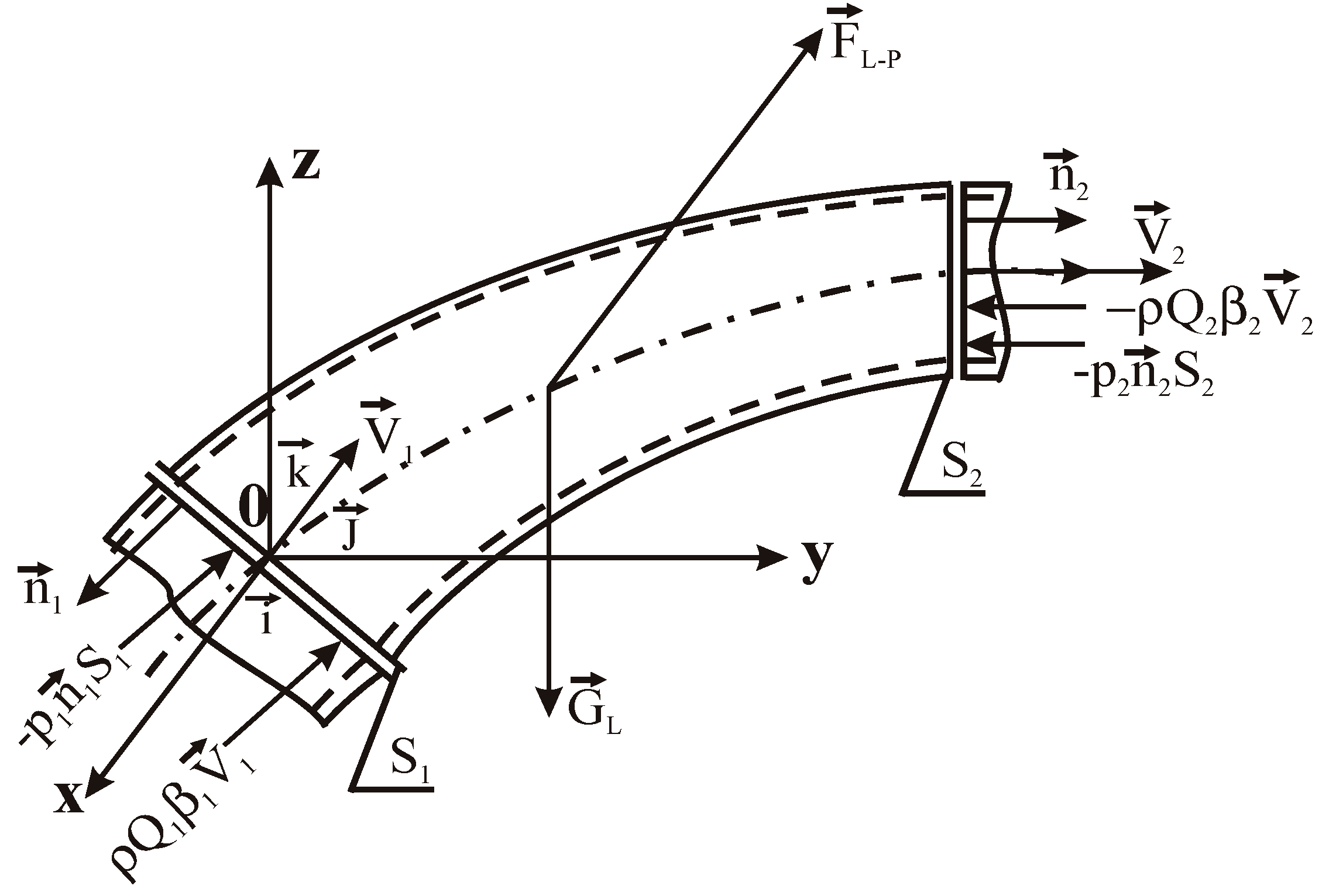
4.1. Analytical Calculus of the Hydrodynamic Force at an Angle α = 45°

Knowing that the hydraulic loads appear at the changes of direction of the pipe, the problem of the analytical calculus of the hydrodynamic force that appears in a corner of the network is studied ([33,34], in order to illustrate the level of the force to be supported by the anchor mass. The following shows the calculation of this force, exerted on an angle of angle α = 45° and of diameter d = 315 mm, located in the horizontal plane (Figure 13), through which water flows, having the flow rate Q = 300 l/s and the pressure p = 15 at. The purpose is to see the load in case of constant pressure flow, without taking into account the hydraulic losses. All of this is done in order to obtain the level of force to which the wall of the pipe must resist, as a justification of the objectives regarding the mechanical experiments and the modeling with the MEF of the elbow-massif assembly. The calculus methodology is the one used in [35].
The following will be used in the calculus:
  • the theorem of momentum to determine the hydrodynamic force on the wall of the pipe;
  • the continuity equation;
  • Bernoulli’s formula.
The theorem of momentum can be written:
ρ Q ( v 2 v 1 ) = R ( p 1 ) + R ( p 2 ) + R g R
Or:
F L P = ρ Q 1 β 1 v 1 ρ Q 2 β 2 v 2 p 1 n 1 s 1 p 2 n 2 s 2 + G L
And comparing with (1) it results:
F L P = R ; ρ Q 1 β 1 v 1 ρ Q 2 β 2 v 2 = ρ Q ( v 2 v 1 ) ;   ( if   β 1   =   β 2 )
p 1 n 1 s 1 = R ( p 1 ) ; p 2 n 2 s 2 = R ( p 2 ) ; G L = R g .
Projecting on the coordinate axes we have:
ρ Q ( v 2 cos α v 1 ) = p 1 π d 2 4 p 2 π d 2 4 cos α R x ; ρ Q ( v 2 sin α 0 ) = 0 p 2 π d 2 4 sin α R y .
From the equation of continuity the flow velocity is obtained:
v 1 = v 2 = v = 4 Q π d 2 = 4 300 10 3 π 0 , 315 2 = 3.849 m s .
From Bernoulli’s relation, considering that we have the elbow horizontally and that there are no losses in the elbow, it results:
p 1 = p 2 = p
Taking into account relations (6) and (7) and replacing them in relations (5), we obtain:
R x = ( 1 cos α ) ( p π d 2 4 + ρ Q v ) ; R y = sin α ( p π d 2 4 + ρ Q v ) .
Knowing that: 1 a t = 9.81 10 4 N m 2 and replacing values in relationships (8), it results:
R x = 5.001 10 4 ( N ) ;   R y = 8.96 10 4 ( N ) ;   R   =   R x 2   +   R Y 2   = 10 , 26.10 4 ( N ) .

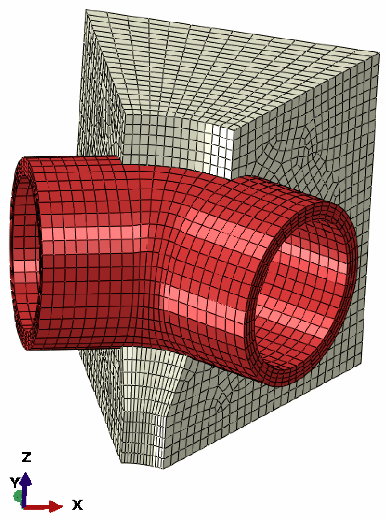
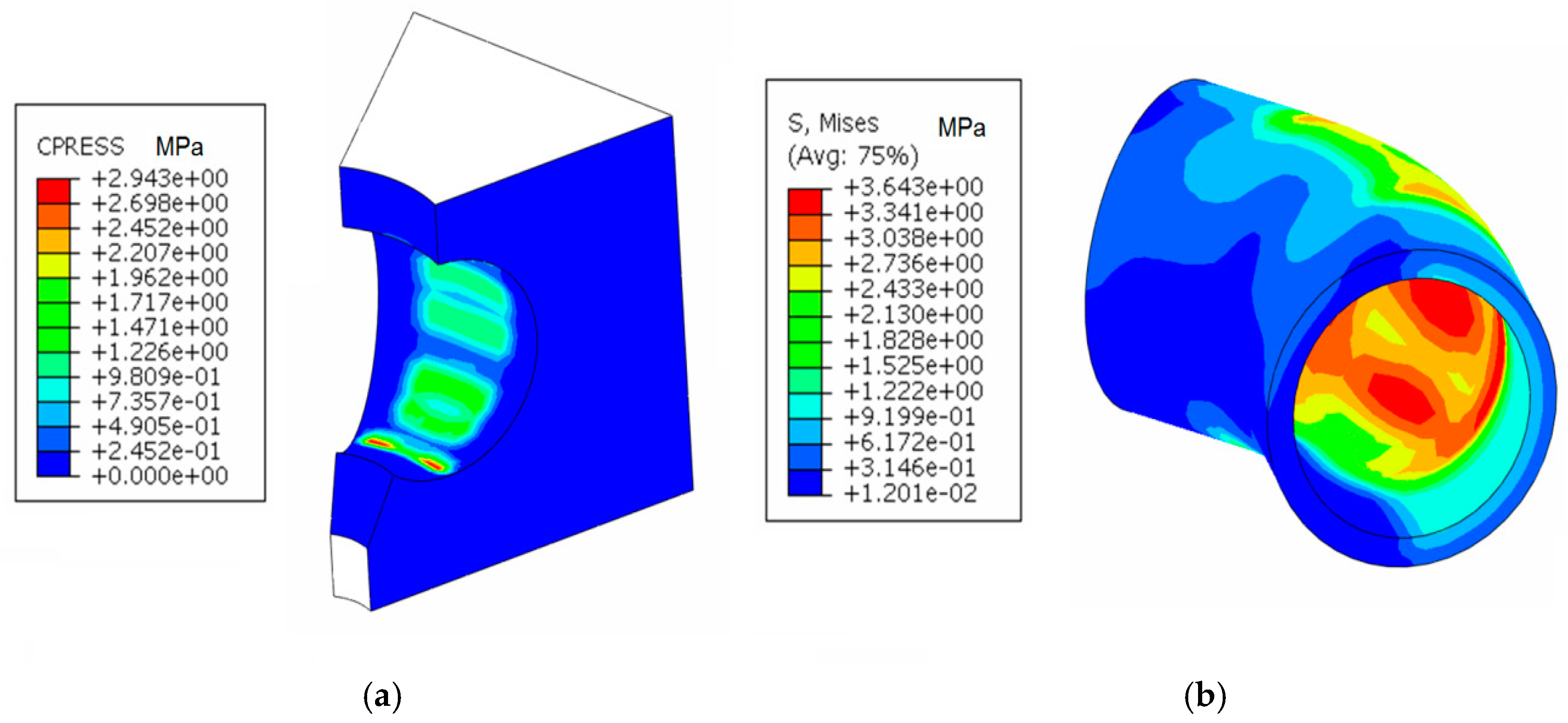
4.2. Structural Model of an Elbow in an Anchorage

The geometric model of an elbow made of HDPE and the discretization of the structural model having a concrete anchorage, are shown in Figure 14. The model has as input data:
  • The pressure inside the elbow, resulting from the analytical calculation, taken as a reference pressure perpendicular to the inner wall of the elbow;
  • Clamping: the ends of the elbow, the concrete anchor on the outside, so that all these degrees of freedom are canceled. Thus, for the performed analysis, the constraints regarding the clamping were imposed, through the input data, to the model.
The contact between the concrete massif and the elbow made of HDPE is considered frictionless. Also, for the sake of simplicity and for the transmission of forces, direct contact was considered.
Discretization of the structural model: total number of knots: 14,985; the total number of elements: 12,370 of which: −12,174 C3D8R type parallelepiped elements; −196 prismatic elements of type C3D6.
For greater accuracy, in the representation of the stresses in the elbow, four elements were used in thickness. The influences of the weight of the concrete, the elbow and the water column were not considered. The values taken for Young’s module are those obtained in the previous section. The following values were considered: density of concrete ρc = 2.3 Kg/m3, Young’s modulus Ec = 2000 MPa, Poisson’s ration νc = 0.2, density of HDPE ρm = 0.97 Kg/m3, Young’s modulus Em = 1300 MPa, Poisson’s ration νm = 0.33. The results of the numerical analysis with MEF of the elbow-massif anchorage assembly are presented in Figure 15. The calculus is made using the pressure of water pa = 5 MPa.
The stresses occurring in the concrete massif are represented in Figure 16, in MPa.
The stress in concrete: maximum 2.035 MPa << σ a = 20 MPa ( σ a is allowable stress). The concrete massif will not be destroyed due to the loads if is executed properly. Contact stress on the contact surface between the elbow and the massif is shown in Figure 17a, in MPa. The mean value of pressure on the surface is: p = 0.66878 MPa (Figure 17a).
The stresses that develop in the elbow are shown in Figure 17b, in MPa. The maximum stress in the elbow is 3.643 MPa << 21.9 MPa, which is the allowable stress of PE 100 type materials. The elbow is well dimensioned and, if properly mounted, it will not be destroyed due to the loads applied to the material in normal use.
Plastic deformation in the elbow is max 0.228% << 840% (breaking elongation of PE 100 type materials). Existing requests for material are not likely to destroy it [36,37,38]. If the elbow fabrication and assembly have been correctly executed and there are no inclusions, micro-cracks or other defects, the use in normal parameters does not destroy the integrity of the elbow material.

4.3. Comparative analysis of the Results Obtained with the MEF in the Case of Elbow DN 315, Buried in the Ground and Anchored in Concrete

Figure 18 presents the structural model MEF of the elbow buried in the ground. The following figures will present the results of the stress and strain analysis performed with MEF [39,40,41]. Three loading cases are analyzed: 1.5 MPa, 5 MPa, 50 MPa. In this section, the results for the 50 MPa load case are presented.
The obtained results, presented in Figure 19, Figure 20, Figure 21, Figure 22, Figure 23 and Figure 24, justify and validate the calculation of crack growth in the case of the elbow buried in the soil, where the stresses and strains are much higher than in the case of the elbow anchored in the concrete. The following values were considered: density of concrete ρc = 2.3 Kg/m3, Young’s modulus Ec = 17,000 MPa, Poisson’s ration νc = 0.15, density of soil ρg = 0.97 Kg/m3, Young’s modulus Eg = 50 MPa, Poisson’s ratio νg = 0.33.
The following numbers and types of elements were used to make the discretized model of the elbow buried in the ground: Number of elbow elements (tetrahedral) = 4933; Number of soil elements (tetrahedral) = 14,022.
The following numbers and types of elements were used to make the discretized model of the elbow anchored in the concrete massif: Number of elbow elements (tetrahedral) = 4933; Number of concrete elements (tetrahedral) = 17,545.

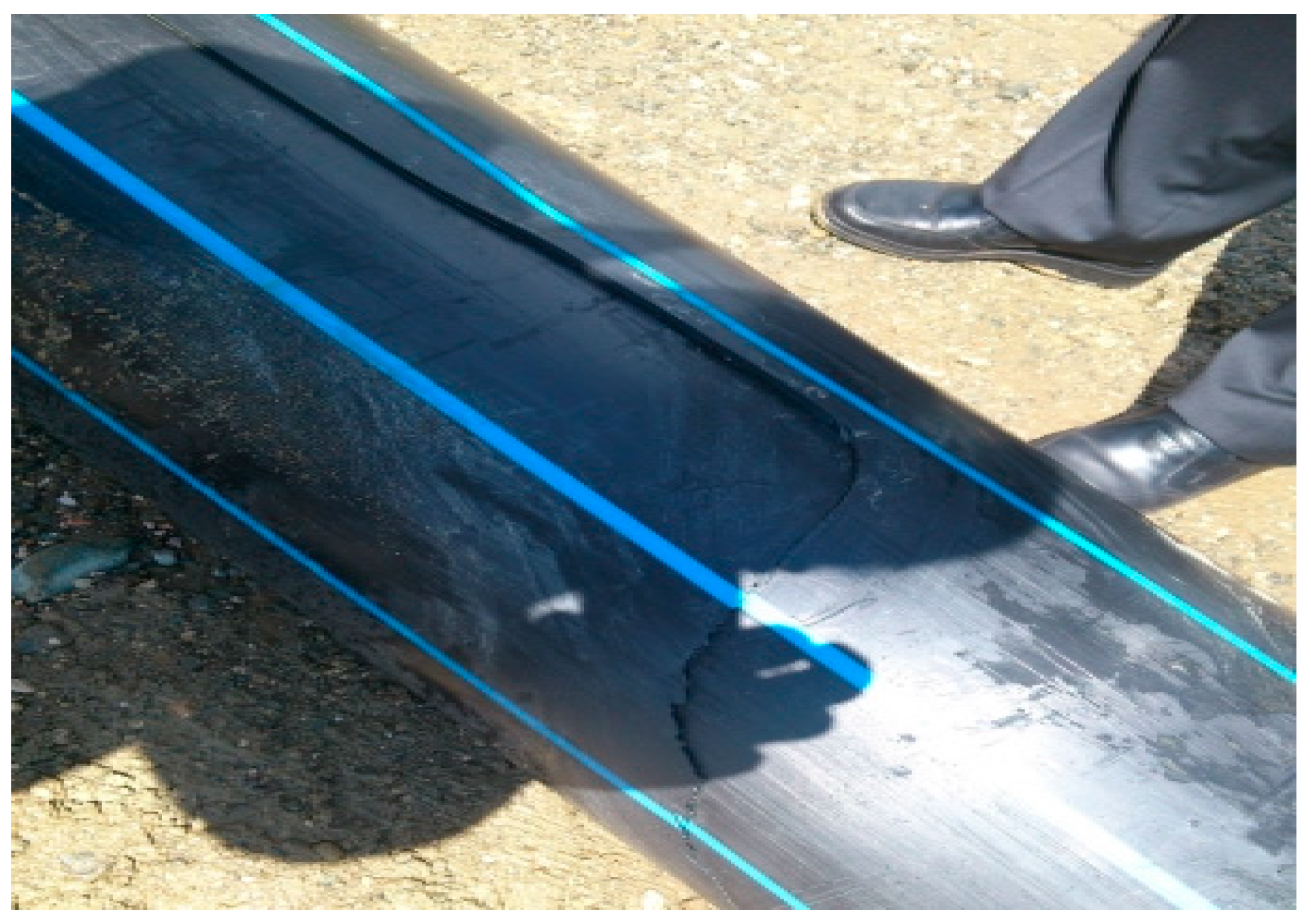
5. Results on HDPE Pipe Damage

Damage of buried pipes, made of HDPE polyethylene, can occur due to several factors [4], which can be grouped as follows:
  • Internal conditions (high pressure, fluctuating pressure, medium-transported temperature);
  • Installation-pipe laying (poor design, laying errors, material handling errors);
  • Damaged material (initial defects, incorrect choice of pipe material, previous crushing);
  • Geothermal forces (bark movements, seismic forces, flotation);
  • External loads (construction loads, heavy traffic, explosions).
In practice, deterioration of HDPE pipes occurs by ductile or brittle crack rupture due to flows [42,43]. A brittle crack is shown in Figure 25.

5.1. FEA of Pipe HDPE-DN 315 Subjected to a Hydraulic Pressure

The model required for the analysis has as input data the pressure inside the pipe, taken as a reference pressure, perpendicular to the inner wall of the pipe and the boundary conditions at the ends of the pipe. The data regarding the pipe, its geometry and its material are: external diameter Dext = 315 mm; internal diameter Dint = 257 mm; thickness t = 28.6; density ρ = 970 kg m3; Young’s modulus E = 1300 MPa; Poisson’s ratio ν = 0.33.
To perform the numerical analysis with MEF, using ABAQUS, the discretized model analysis of the pipe, presented in Figure 26a is created. The discretization was performed using C3D8R type parallelepiped elements. There were generated 2300 elements for the obtained model.

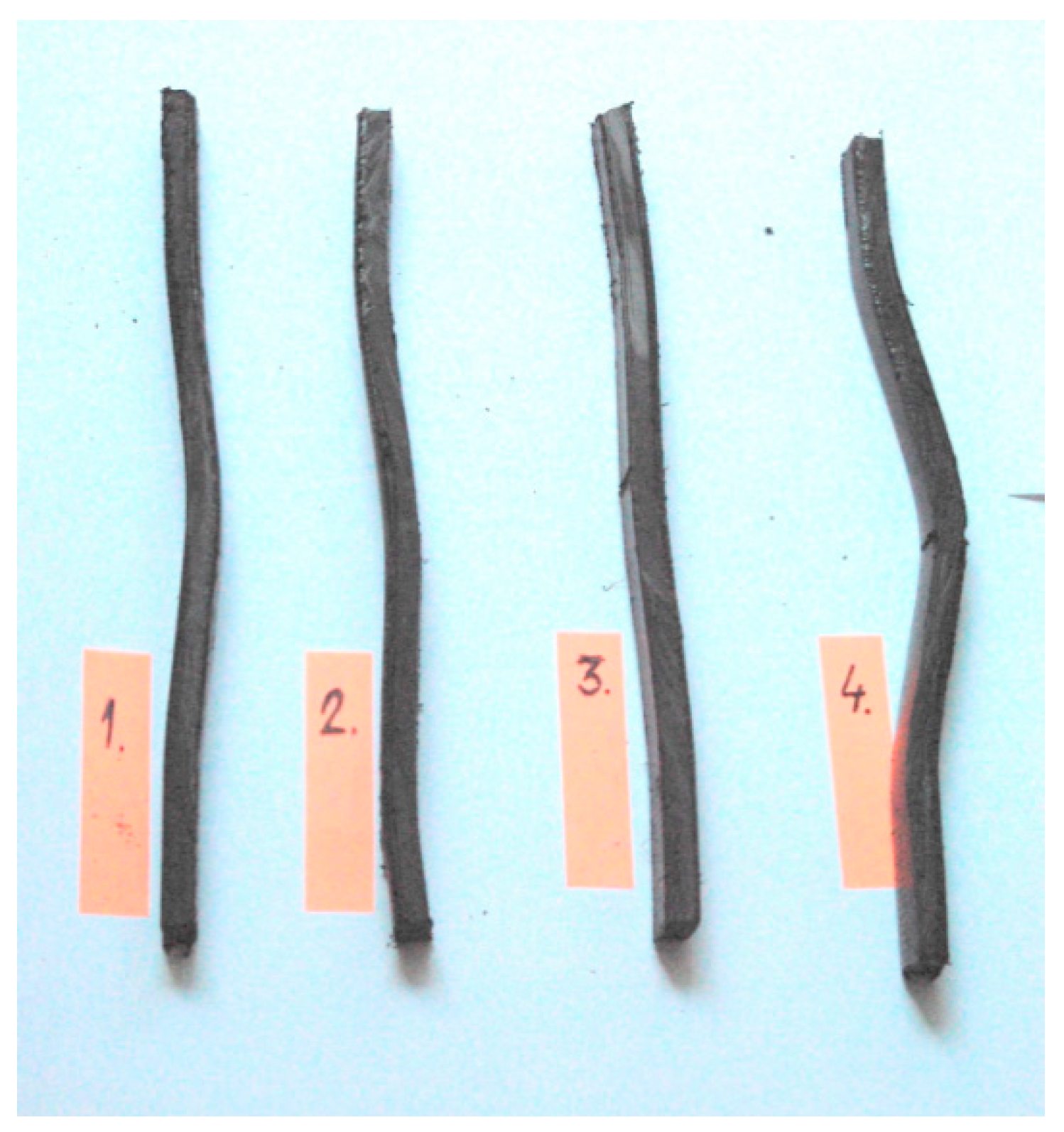
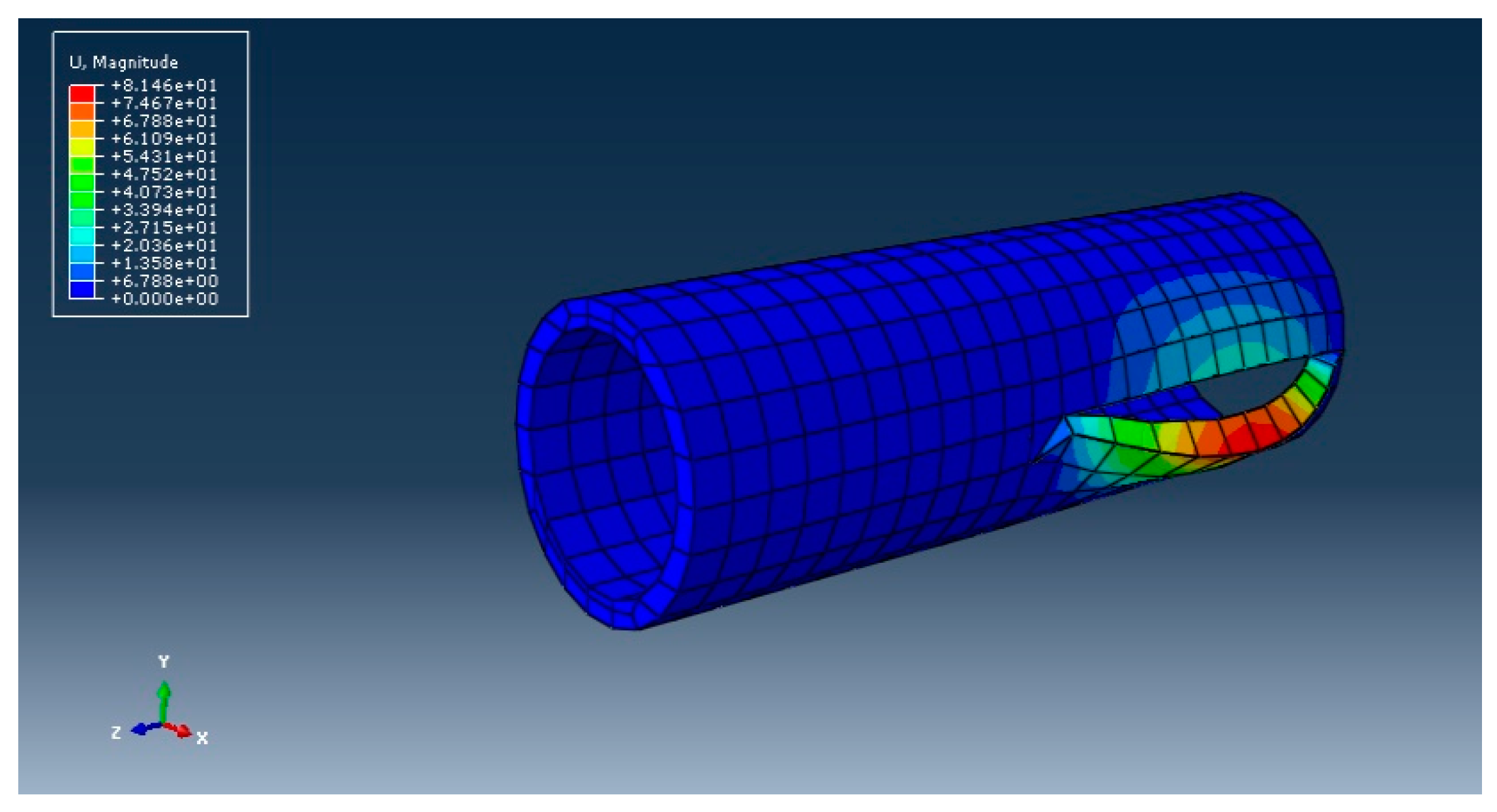
5.2. Simulation of the Ductile Crack of a Straight Pipe

In the following, a simulation of the ductile crack is made for a straight pipe. Currently, this type of pipe is not supported in concrete, but buried directly in the ground. As a result, the analysis of the pipe’s behavior when supported in a concrete massif was not done and there is no comparison between the two solutions (in this case, the current practice of civil engineers is to directly bury pipes in the ground). In the numerical analysis of the crack, Abaqus/CAE 6.14-5 is used with XFEM. The simulation is performed for DN90 distribution pipes and DN315 arteries. The geometric model of the pipe, necessary for the numerical analysis with MEF, will be created and the chosen material of the pipe is HDPE. The steps followed in this analysis are: Creating the solid; Creating the crack strip; Creating the section and setting material properties; Create an additional step for crack development; Create the crack-type interaction; Create the unitary assembly of solid and crack strip; Create the clamping; Create the load on inner surface; Model discretization (Figure 27); Choosing the output calculation parameters; Performing the simulation and obtaining the results. In the analysis of the pipes, only the stress and strain caused by the internal pressure to which they are subjected are considered.
It is now possible to present the cracked model in Figure 28. The crack is ductile and resembles the “parrot’s beak” described in [36]. The crack stress is 130 MPa >>> allowable stress of HDPE. The displacements of the nodes at the crack are presented in Figure 28, in mm.
For the study of the ductile crack of the DN pipes 90 the steps of the analysis are identical to those described previously. The discretized model, with the created interaction of the crack type, is presented in Figure 29a.
The presentation of the broken model is produced as shown in Figure 29b. The crack is ductile and resembles the parrot’s beak described in [36].

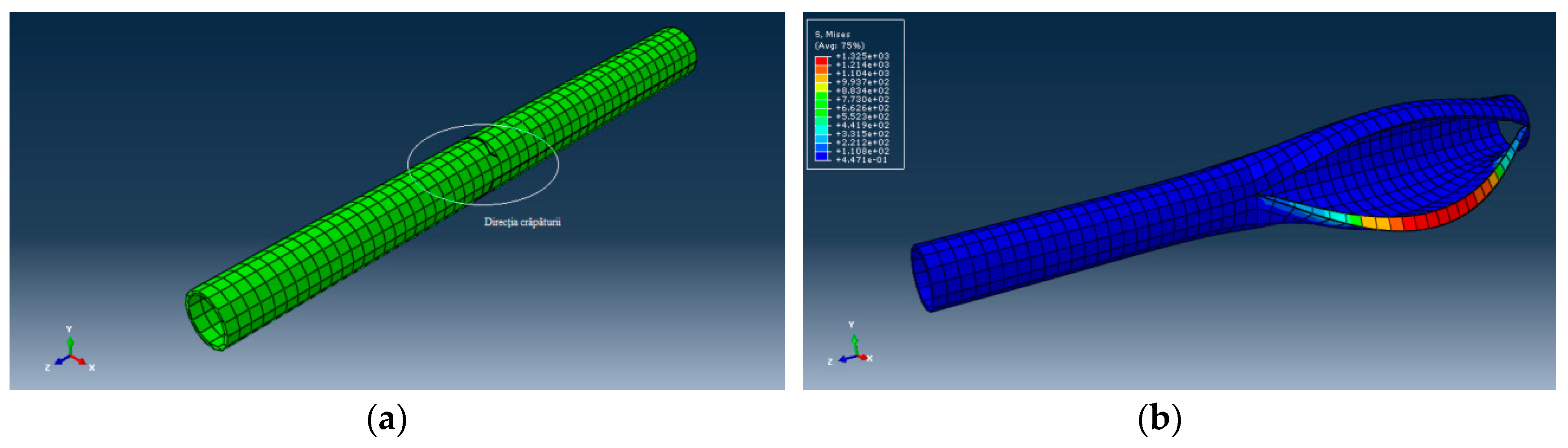
5.3. Study of the Crack of the Elbow DN 315 Buried in the Ground

The geometric model of the DN 315 elbow, made of HDPE, which is not supported in a concrete anchorage, is shown in Figure 30a. The discretized model of Figure 30b will be used to simulate elbow rupture.
The model of pressurized elbow DN 315, which has created the crack-type interaction, as well as the crack strip, is shown in Figure 30b. After performing the numerical analysis with the MEF it is possible to present the broken model. The rupture is ductile and occurs according to the mode shown in Figure 31b, using Abaqus/CAE 6.15 -XFEM.
The stress at which the crack occurred: 250.3 MPa > 21.9 MPa, which is the allowable stress [36] of PE materials (Figure 31).

6. Discussion and Conclusions

A comparison between an elbow buried in the ground and one anchored in a massif concrete was presented, showing the advantages of the solution of the elbow anchored in concrete. Using MEF, the stresses and strains that appear in the elbow-massif anchorage assembly, as well as in the pressurized pipe of the entire water supply network were determined.
From the analysis of the obtained results we can formulate the following conclusions:
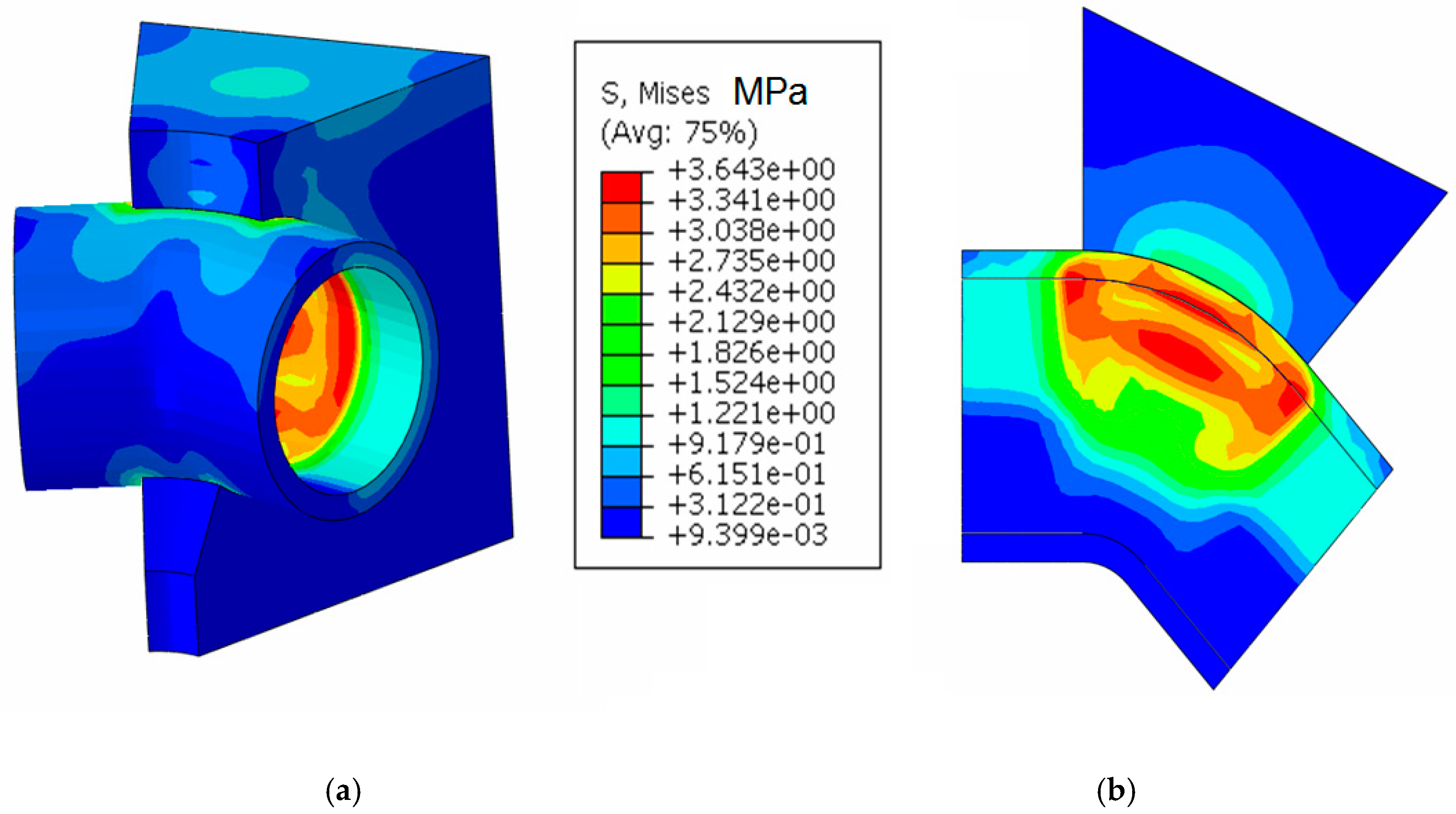
  • The maximum stress the concrete massif (Figure 16) was: σ max = 2.035 M P a < σ a = 20 M P a so that the concrete massif will not be destroyed due to the existing load;
  • The maximum stress in the elbow was σ max , = 3.643 M P a < σ a = 21.9 M P a so that the elbow will not be destroyed due to the working demands;
  • The plastic deformation in the elbow (Figure 17), at stretch, max 0.228 % << 840% which is the specific elongation at break for HDPE [36];
  • The comparison between elbow DN 315 buried in the ground and elbow DN 315 anchored in concrete mass, presented in Figure 19, Figure 20, Figure 21, Figure 22, Figure 23 and Figure 24, where the values of tension and deformation are shown in soil and concrete, justify anchoring the elbow in the concrete massif.
The results obtained during the work can be useful to a designer in the case of building a water supply network. They refer to pipes made of HDPE, a wide material used in practice. For the same pipe size, but coming from different manufacturers, a user can make the difference, not only based on the price but knowing the material characteristics resulting from mechanical tests. The paper presented very useful information for specialists who use polyethylene pipes. The results of the work can be materialized in:
  • The proposal of quality assurance and control systems for receiving pipes, which will comply in all respects with the conditions of the reference standards;
  • Elaboration of quality control procedures of the companies that manage the water networks, with the right of these companies to control or try the products they purchase during any stage of their manufacture, which can affect the quality of the products and also the possibility of testing the raw materials used in the manufacture of pipes or fittings;
  • Elaboration of storage techniques of all the information attesting the quality of the product delivered by a certain supplier and the possibility of comparing price/quality analysis, but also the knowledge of the mechanical characteristics, for similar products from different suppliers;
  • Introducing in the quality system the mention “the obligation of the supplier of plastic pipes to present the regression diagrams of the pipe material”;
  • The digital map of the network and the study of rings with specialized software (EPANET, WATERCAD);
  • Requesting an express requirement of the beneficiary of the plastic pipe—in the manufacture of the batch of pipes, molds, and samples of the same material as one of the pipes are made, known that for mechanical tests, the samples must have a certain form [36].
The obtained results and their benefits can be transferred to the designers of water supply networks, networks that are found in most localities in the areas of the modern world.

Author Contributions

Conceptualization, S.V., M.M., M.L.S.; methodology, S.V., D.D.S.; software, D.D.S. and M.L.S.; validation, S.V., M.M. and C.C.; formal analysis, S.V.; investigation, D.D.S. and M.L.S.; resources, D.D.S., S.V. and C.C.; data curation, D.D.S., M.L.S.; writing—original draft preparation, D.D.S. and M.L.S.; writing—review and editing, S.V., M.M. and C.C.; visualization, C.C.; supervision, S.V., M.M.; project administration, S.V.; funding acquisition, D.D.S., S.V. All authors have read and agreed to the published version of the manuscript.

Funding

This research was funded by WATER Company, Brasov.

Acknowledgments

We want to thank the reviewers who have read the manuscript carefully and have proposed pertinent corrections that have led to an improvement in our manuscript.

Conflicts of Interest

The authors declare no conflict of interest.

References

  1. Available online: https://www.youtube.com/watch?v=e7uypR7RUoQ (accessed on 2 January 2020).
  2. Available online: https://www.uponor.com/int/products/drinking-water-delivery/flexible-pipe-system (accessed on 2 January 2020).
  3. Available online: https://www.wavin.com/en-en/solutions/solutions-for-drinking-water (accessed on 2 January 2020).
  4. Williams, J.G. Fracture Mechanics of Polymers; Elis Horwood Limited: California, USA, 1984. [Google Scholar]
  5. Ayres, R.L. Basics of Polyethylene Manufacture Structureand Properties. In Proceedings of the American Gas Association Distribution Conference Anaheim, Los Angeles, CA, USA, 1981. [Google Scholar]
  6. Harper, C.A. Handbook of Plastics and Elastomers; Mc Graw-Hill Book Company: New York, NY, USA, 1975. [Google Scholar]
  7. Powell, P.C. Engineering with Polymers; Chapman and Hall: London, UK, 1982. [Google Scholar]
  8. Zhang, J.F.; Li, Y.; Xing, D.; Wang, Q.W.; Wang, H.G.; Koubaa, A. Reinforcement of continuous fibers for extruded wood-Flour/HDPE composites: Effects of fiber type and amount. Constr. Build. Mater. 2019, 228, 1–8. [Google Scholar] [CrossRef]
  9. Zhou, M.; Moore, I.D.; Lan, H.T. Experimental Study of Structural Response of Lined-Corrugated HDPE Pipe Subjected to Normal Fault. J. Geotech. Environ. Eng. 2019, 145, 04019117. [Google Scholar] [CrossRef]
  10. Sayem, A.M.; Haider, J.; Sayeed, M.A. Development and characterisation of multi-Layered jute fabric-Reinforced HDPE composites. J. Compos. Mater. 2019. [Google Scholar] [CrossRef]
  11. Kashfipour, M.A.; Guo, M.L.; Mu, L.W.; Mehra, N.; Cheng, Z.H.; Olivio, J.; Zhu, S.S.; Maia, J.M.; Zhu, J.H. Carbon nanofiber reinforced Co-Continuous HDPE/PMMA composites: Exploring the role of viscosity ratio on filler distribution and electrical/thermal properties. Compos. Sci. Technol. 2019, 184, 107859. [Google Scholar] [CrossRef]
  12. Gama, N.; Barros-Timmons, A.; Ferreira, A.; Evtuguin, D. Surface treatment of eucalyptus wood for improved HDPE composites properties. J. Appl. Polym. Sci. 2019, 48619. [Google Scholar] [CrossRef]
  13. Mosavi-Mirkolaei, S.T.; Najafi, S.K.; Tajvidi, M. Physical and Mechanical Properties of Wood-Plastic Composites Made with Microfibrillar Blends of LDPE, HDPE and PET. Fibers Polym. 2019, 20, 2156–2165. [Google Scholar] [CrossRef]
  14. Singh, N.; Singh, R.; Ahuja, I.P.S. Thermomechanical investigations of SiC and Al2O3-Reinforced HDPE. J. Thermoplast. Compos. Mater. 2019, 32, 1347–1360. [Google Scholar] [CrossRef]
  15. Awad, A.H.; Abd El-Wahab, A.A.; El-Gamsy, R.; Abdel-latif, M.H. A study of some thermal and mechanical properties of HDPE blend with marble and granite dust. Ain Shams Eng. J. 2019, 10, 353–358. [Google Scholar] [CrossRef]
  16. Sun, Y.; Jia, Y.F.; Haroon, M.; Lai, H.S.; Jiang, W.C.; Tu, S.T. Welding Residual Stress in HDPE Pipes: Measurement and Numerical Simulation. J. Press. Vessel Technol.-Trans. ASME 2019, 141, 041404. [Google Scholar] [CrossRef]
  17. Zheng, X.T.; Zhang, X.H.; Ma, L.W.; Wang, W.; Yu, J.Y. Mechanical characterization notched high density polyethylene (HDPE) pipe: Testing and prediction. Int. J. Press. Vessels Pip. 2019, 173, 11–19. [Google Scholar] [CrossRef]
  18. Majid, F.; Elghorba, M. Critical lifetime of HDPE pipes through damage and reliability models. J. Mech. Eng. Sci. 2019, 13, 5228–5241. [Google Scholar]
  19. Ghabeche, W.; Chaoui, K. An Investigation into Property Variances Between Outer and Inner HDPE Pipe Layers. Mechanika 2019, 25, 99–106. [Google Scholar] [CrossRef]
  20. Kilic, H.; Akinay, E. Investigation of Buried HDPE Pipe Deflection Behavior. Teknik Dergi 2018, 30, 9373–9398. [Google Scholar]
  21. Bouaziz, M.A.; Guidara, M.A.; Schmitt, C.; Hadj-Taieb, E.; Azari, Z.; Dmytrakh, I. Structural integrity analysis of HDPE pipes for water supplying network. Fatigue Fracture Eng. Mater. Struct. 2019, 42, 792–804. [Google Scholar] [CrossRef]
  22. Duan, H.-F.; Ghidaoui, M.S.; Lee, P.J.; Tung, Y.-K. Unsteady friction and visco-Elasticity in pipe fluid transients. J. Hydraul. Res. 2010, 48, 354–362. [Google Scholar] [CrossRef]
  23. Duan, H.F.; Ghidaoui, M.S.; Yeou-Koung, T. Energy Analysis of Viscoelasticity Effect in Pipe Fluid Transients. J. Appl. Mech. 2010, 77. [Google Scholar] [CrossRef]
  24. Pan, B.; Duan, H.F.; Meniconi, S.; Urbanowicz, K.; Che, T.C.; Brunone, B. Multistage frequency-Domain transient-Based method for the analysis of viscoelastic parameters of plastic pipes. J. Hydraul. Eng.–ASCE 2020, 146, 04019068. [Google Scholar] [CrossRef]
  25. Tscheikner-Gratl, F.; Sitzenfrei, R.; Rauch, W.; Kleidorfer, M. Enhancement of limited water supply network data for deterioration modelling and determination of rehabilitation rate. Struct. Infrastruct. Eng. 2018, 12, 366–380. [Google Scholar] [CrossRef]
  26. Malinowski, J. A Newly Developed Method for Computing Reliability Measures in a Water Supply Network. Oper. Res. Decis. 2016, 26, 49–64. [Google Scholar]
  27. Szpak, D.; Tchorzewska-Cieslak, B. Modelling of failure rate of water supply network using the Bayes theorem. In Proceedings of the 10TH Conference on Interdisciplinary Problems in Environmental Protection and Engineering EKO-DOK, Polanica-Zdrój, Poland, 16–18 April 2018; Volume 44, p. AR 00175. [Google Scholar]
  28. Zhang, S.H.; Yang, J.S.; Wan, Z.Y.; Yi, Y.J. Multi-Water Source Joint Scheduling Model Using a Refined Water Supply Network: Case Study of Tianjin. Water 2018, 10, 1580. [Google Scholar] [CrossRef] [Green Version]
  29. Hughes, T.J.R. The Finite Element Method: Linear Static and Dynamic Finite Element Analysis; Prentice Hall: Englewood Cliffs, NJ, USA, 2000. [Google Scholar]
  30. Available online: http://manual.1search.cc/search.php?utm_source=abaqus%20analysis%20user%27s%20manual%206.14%20vol%202%20pdf (accessed on 2 January 2020).
  31. Modrea, A.; Hebert, H.; Scǎrlǎtescu, D.D. FEM Applied to Determine the Stress-strain Field in the Tubes of the Water Supply Networks. Procedia Manuf. 2019, 32, 187–193. [Google Scholar] [CrossRef]
  32. Modrea, A.; Scǎrlǎtescu, D.D.; Gligor, A. Mechanical Behavior of the HDPE Tubes Used in Water Supply Networks Determined with the Four-Point Bending Test. Procedia Manuf. 2019, 32, 194–200. [Google Scholar] [CrossRef]
  33. Florea, J.; Seteanu, I.; Zidaru, G.; Pancutescu, V. Technical Description for Polyethylene Pipes. Fluid Mechanics and Hydropneumatic Machines; Didactic and Pedagogical Publishing House Bucharest: Bucharest, Romania, 1982. [Google Scholar]
  34. Bordeaşu, I.Ș.A. Theoretical Notions and Problems of Hydrodynamics, Pipes, Channels and Hydraulic Machines; Politehnica Publishing House: Timişoara, Romania, 2005. [Google Scholar]
  35. Bordeaşu, I.; Baciu., I.D. Applied Hydraulics. Hydrostatic. Theoretical Notions and Applications; Politehnica Publishing House: Romania, 2002. [Google Scholar]
  36. Available online: http://www.performancepipe.com/en-us/Documents/PPI%20Handbook.pdf (accessed on 2 January 2020).
  37. Dumitrescu, I.; Marşavina, L. Introduction to Fracture Mechanics; Mirton Publishing House: Timişoara, Romania, 2001. [Google Scholar]
  38. Posea, N.; Anghel, A.; Grigore, N.; Mincu, V. Statics and Dynamics of Pipeline Systems; Romanian Academy Publishing House: Bucharest, Romanian, 1996. [Google Scholar]
  39. Vlase, S.; Scărlătescu, D.D.; Scutaru, M.L. Stress Field in Tubes Made of High Density Polyethylene Used in Water Supply Systems. Acta Tech. Napoc. 2019, 62, 273–280. [Google Scholar]
  40. Vlase, S.; Scărlătescu, D.D.; Marin, M.; Öchsner, A. Finite Element Analysis of an Elbow Tube in Concrete Anchor Used in Water Supply Networks. J. Mater. Des. Appl. J. Mater. Des. Appl. 2019. [Google Scholar] [CrossRef]
  41. Scărlătescu, D.D.; Vlase, S.; Crisan, A. Traction Test to Determine the Behaviour of the Materials Used in Water Supply Networks. Acta Tech. Napoc. Ser.-Appl. Math. Mech. Eng. 2019, 62, 175–182. [Google Scholar]
  42. Rueda, F.; Marquez, A.; Otegni, J.L.; Frontini, P.M. Buckling collapse of HDPE liners. Experimental set-Up and FEM simulations. Thin-Walled Struct. 2016, 109, 103–112. [Google Scholar] [CrossRef]
  43. Citarella, R.; Lepore, M.; Maligno, A.; Shlyannikov, V. FEM simulation of a crack propagation in a round bar under combined tension and torsion fatigue loading. Fract. Struct. Integrit. 2015, 31, 138–147. [Google Scholar] [CrossRef] [Green Version]
Figure 1. The water supply network of a medium-sized city.
Applsci 10 01658 g001
Figure 2. Pipes of different sizes used in water supply networks (for connections, arteries and distribution).
Applsci 10 01658 g002
Figure 3. Diagram stress-strain for traction, tub Φ20 × 2.
Applsci 10 01658 g003
Figure 4. Diagram stress-strain for traction test, pipe Φ63 × 4.
Applsci 10 01658 g004
Figure 5. Specimens after traction test.
Applsci 10 01658 g005
Figure 6. Extensometer used in the experiment.
Applsci 10 01658 g006
Figure 7. Diagram stress-strain for traction test, pipe Φ90 × 6.
Applsci 10 01658 g007
Figure 8. Samples of HDPE pipe Φ90 × 6 broken at traction.
Applsci 10 01658 g008
Figure 9. Diagram stress-strain for compression test, pipe Φ90 × 6.
Applsci 10 01658 g009
Figure 10. Compression test specimens.
Applsci 10 01658 g010
Figure 11. Extensometer used.
Applsci 10 01658 g011
Figure 12. Diagram stress-strain for traction test, pipe Φ90 × 6.
Applsci 10 01658 g012
Figure 13. Pipe elbow in a horizontal plane [31].
Applsci 10 01658 g013
Figure 14. Discretization of the structural model.
Applsci 10 01658 g014
Figure 15. (a) Stress field in the assembly elbow-massif (b) Stress distribution in a section of the assembly.
Applsci 10 01658 g015
Figure 16. Stresses in the concrete massif.
Applsci 10 01658 g016
Figure 17. (a) Contact pressures on the surface of the massif; (b) Polyethylene elbow stresses.
Applsci 10 01658 g017
Figure 18. Structural model of the elbow buried in the soil.
Applsci 10 01658 g018
Figure 19. Displacements in a section of massif, in mm (load pressure 50 MPa).
Applsci 10 01658 g019
Figure 20. Displacements in elbow, in mm (load pressure 50 MPa).
Applsci 10 01658 g020
Figure 21. Displacements in section of elbow, in mm (load pressure 50 MPa).
Applsci 10 01658 g021
Figure 22. Pressure on the outer surface of elbow, in MPa (load pressure 50 MPa).
Applsci 10 01658 g022
Figure 23. Stresses von Mises in elbow, in MPa (load pressure 50 MPa).
Applsci 10 01658 g023
Figure 24. Stresses von Misses in elbow, in a section, in MPa (load pressure 50 MPa).
Applsci 10 01658 g024
Figure 25. Brittle crack of pipe (photo Scarlatescu).
Applsci 10 01658 g025
Figure 26. Results for the pipe DN 315.
Applsci 10 01658 g026
Figure 27. Crack analysis model of DN 315 pipe.
Applsci 10 01658 g027
Figure 28. Displacements of the nodes at the crack for the pipes DN315.
Applsci 10 01658 g028
Figure 29. (a) Crack analysis model of pipe DN 90 and (b) Broken model of pipes DN 90.
Applsci 10 01658 g029
Figure 30. (a) Geometrical model of the elbow DN 31; (b) FE model of the elbow DN 315.
Applsci 10 01658 g030
Figure 31. Elbow DN 315 after cracking.
Applsci 10 01658 g031

