Article

Virtual View Synthesis Based on Asymmetric Bidirectional DIBR for 3D Video and Free Viewpoint Video

Key Laboratory of Opto-electronics Information Technology (Tianjin University), Ministry of Education, School of Precision Instrument & Opto-electronics Engineering, Tianjin University, Tianjin 300072, China
*
Author to whom correspondence should be addressed.
Appl. Sci. 2020, 10(5), 1562; https://doi.org/10.3390/app10051562
Submission received: 31 January 2020 / Revised: 14 February 2020 / Accepted: 23 February 2020 / Published: 25 February 2020
(This article belongs to the Section Computing and Artificial Intelligence)

Abstract

:
Depth image-based rendering (DIBR) plays an important role in 3D video and free viewpoint video synthesis. However, artifacts might occur in the synthesized view due to viewpoint changes and stereo depth estimation errors. Holes are usually out-of-field regions and disocclusions, and filling them appropriately becomes a challenge. In this paper, a virtual view synthesis approach based on asymmetric bidirectional DIBR is proposed. A depth image preprocessing method is applied to detect and correct unreliable depth values around the foreground edges. For the primary view, all pixels are warped to the virtual view by the modified DIBR method. For the auxiliary view, only the selected regions are warped, which contain the contents that are not visible in the primary view. This approach reduces the computational cost and prevents irrelevant foreground pixels from being warped to the holes. During the merging process, a color correction approach is introduced to make the result appear more natural. In addition, a depth-guided inpainting method is proposed to handle the remaining holes in the merged image. Experimental results show that, compared with bidirectional DIBR, the proposed rendering method can reduce about 37% rendering time and achieve 97% hole reduction. In terms of visual quality and objective evaluation, our approach performs better than the previous methods.

1. Introduction

In recent years, three-dimensional (3D) video has become one of the most popular multimedia types. It can provide audience with an immersive visual experience [1]. Free viewpoint video (FVV) is regarded as an upgraded version of 3D video, which enable the users to freely choose the viewpoint within a certain range [2]. Accordingly, the capture and transmission of FVV requires a large number of cameras and expensive bandwidth [3]. In [4], a realtime compression architecture for 4D performance capture is proposed to realize real-time transmission of 3D data sets while achieving comparable visual quality and bitrate. An encoder that leverages an implicit representation is introduced to represent the observed geometry, as well as its changes through time. On the decoder side, a variational optimization that compensates for quantization residuals is applied to avoid the typical artifacts of block-based coding. In practical applications, it is difficult to configure cameras for all views to achieve free switching of viewpoints [5]. In this case, one practical way is to transmit only one or several key viewpoints, and the images of other views are synthesized at the receiving end. As described in [6], a wavelet approach allows the researcher to have information not only on frequencies but even on time. It can obtain all the frequencies which are present in a signal with a good resolution. Therefore, wavelet transform is helpful for 3D-image coding and compression, and improves the quality of data transmission. Pandey et al. [7] propose a virtual view synthesis method using a single Red-Green-Blue-Depth (RGBD) camera. It can generate novel renderings of the performer based on the past observations from multiple viewpoints and the current RGBD image from a fixed view. Lombardi et al. [8] present a modeling method for objects and scenes with a semi-transparent volume representation based on end-to-end learning from multi-view RGB images, and the virtual view can be synthesized based on the 3D model. However, these methods are implemented on the basis of machine learning or deep learning. Therefore, the collection of training data is very important and limits the applicable scenarios for view synthesis. For newly added scenes or insufficient training sets, the performance of algorithms based on machine learning will decrease. Depth image-based rendering (DIBR) is a reliable technique for view synthesis in these cases [9]. It introduces depth information into view synthesis and need not to reconstruct a 3D model. As shown in Figure 1, all pixels in the reference image are projected to the 3D world coordinate based on the depth value and camera parameters, forming a set of 3D point clouds. The resulting points are then reprojected into the target image plane based on the virtual camera parameters. This core process is called 3D warping.
In the 3D warping process, there would be some artifacts in the synthesized image, resulting in a reduction of visual quality. According to the causes and features, these artifacts can be divided into several types: ghosts, cracks, pixel overlap, and holes [10]. Ghosts are usually pixels on the foreground edges. In the depth acquisition process, they are given the background depth values, which makes the foreground edges in a depth image mismatched with that of the color image. Cracks are caused by rounding errors when warping 3D points to the target image. Due to the change of viewpoint in 3D warping, the occlusion relationship between objects in the scene has also changed, which is manifested in two forms. On the one hand, multiple pixels in the reference image may be projected into the same position in the virtual image, as shown in Figure 2. These pixels usually have different depth values, which means they are at different distances from the reference camera. Therefore, the proper approach should be introduced to maintain the correct occlusion relationship. On the other hand, background regions occluded by foreground objects might be exposed in the virtual view. Since no pixels are warped to these regions, large holes appear in the virtual image, called disocclusions [11]. Moreover, there is another type of hole known as the out-of-field region (OFR). This appears because the virtual view exceeds the capture range of reference view, resulting the region with no information on the edge of virtual image. Therefore, artifacts handling hole filling in particular are a key issue for view synthesis.
Generally, the hole-filling methods can be divided into two categories. The first is to preprocess the depth image by introducing a low-pass filter to reduce the hole size. The generation of disocclusion is related to the depth discontinuity between the foreground and the background. Large depth discontinuity usually causes a large disocclusion. Tam et al. [12] use a symmetric Gaussian filter to smooth the depth image, aiming to reduce the depth discontinuity on the foreground edge and remove isolated noise pixels. However, this method produces a rubber plate effect, which appears as an uneven enlargement of the object. An asymmetric Gaussian filter is proposed in [13] to overcome this problem and give stronger smoothness to depth discontinuity in a vertical direction. However, the regions that do not produce disocclusion are also smoothed, causing some distortion in the virtual image and reducing the visual quality of these regions. In this case, an edge-based smoothing filter is proposed to preprocess the foreground edge only [14]. Liu et al. [15] implement preprocessing in the transformed domain by applying a structure-aided filter. An adaptive filter can prevent the generation of hole or decrease hole size to some extent. The depth image-smoothing methods are suitable for small baseline configurations. They are hardly used in the large baseline situation. Moreover, OFRs are not caused by depth discontinuities, so they would not be prevented by the smoothing process.
The other type of method is to fill the holes by using the texture correlation of surrounding pixels. Inpainting-based methods are effective solutions to fill the unknown regions, such as Criminisi’s exemplar-based inpainting algorithm [16]. In this method, the filling priority is first computed based on the texture distribution of surrounding valid pixels, and then the best matching patch in the source region is searched and copied to the hole region. It can produce plausible results without introducing blurring effects. However, for disocclusion filling, as the exposed regions belong to the background, they should be filled with background texture. Directly applying the Criminisi’s method would cause some foreground textures to be sampled to fill the holes, resulting in foreground blending. To overcome this drawback, some methods optimize the inpainting process by introducing the depth features. In [17], the depth term is added in priority computation to give the patch with lower depth variance a higher priority, and depth weight is considered when searching for the best matching patch. However, this method requires the known depth image of virtual view, which is unrealistic in practical applications. Ahn et al. [18] synthesizes the virtual depth image in 3D warping, thereby providing depth information for the subsequent inpainting process. But when the depth value of foreground edge is inaccurate, ghosts would affect the hole-filling quality. A depth-based gray-level distance matching cost computation method is proposed in [19], but some artifacts might be produced due to the depth errors. In order to prevent the interference of foreground texture, some foreground segmentation methods are proposed [20,21,22]. The quality of the synthesized image through these methods is strongly dependent on the accuracy of foreground segmentation. This is a challenging task in some situations, such as the existence of multiple depth layers. Sometimes the seed points need to be manually identified.
In the case where more than one reference view is available, the hole filling would be easier than single-view rendering. Multiple views can cover a larger capture range, and the occluded regions in the primary view may be visible in the auxiliary view. Li et al. [23] verify that the hole size can be further reduced by using two or more auxiliary views. In [24], an improved multiview synthesis method is proposed. The virtual view is synthesized by rendering the two nearest views, and for disocclusion filling, the hole regions are filled by the information from all of the additional views. The whole synthesis process is conducted with triangles instead of single pixels. Color of the pixels inside the triangle is linearly interpolated based on the colors and positions of the respective vertices. This process can reduce the hole size, but for regions with rich textures, interpolation computations may cause a distortion of the structure and introduce blurring results. Correspondingly, warping all of the additional views increases the computational cost. In particular, as the number of auxiliary views increases, the area of hole that can be further filled by merging is greatly reduced. In addition, transmitting so much data requires higher bandwidth. Therefore, bidirectional rendering is still a common approach for view synthesis. For this method, some holes still remain after merging as they are not visible in both views. The holes caused by depth errors are also difficult to avoid. In [25], a modified Gaussian mixture model (GMM) method is proposed to build the background model, aiming to fill the remaining holes after weighted merging. This method cannot obtain the occluded background contents when the foreground objects are stationary. In [26], a horizontal background extrapolation method is applied to fill the holes. Although its computational complexity is low, pixel-based filling results lack realism, especially for complex backgrounds. Yao et al. [27] propose a depth-aided inpainting method to deal with the remaining holes. These bidirectional rendering methods perform the full 3D warping process for all the reference views. In fact, a large part of the regions is visible in both views. In [28], the virtual depth image is inpainted to search the hole regions in the auxiliary image, thus preventing the repeated warping of the common regions. But filling the holes in the depth image increases the computational complexity. The visual quality of a synthesized image depends on the accuracy of depth prediction.
In this paper, we propose an asymmetric bidirectional rendering method for virtual view synthesis. The main contributes are: (1) pixels around foreground edges are optimized in the primary depth image before 3D warping, which can correct the depth value of foreground edges and prevent the ghosts from appearing on disocclusion boundaries. (2) We combine forward and reverse 3D warping to explore the occlusion layer of the primary view in the auxiliary image. By contrast with the traditional method which warps the whole two images and blends them, our method only warps the primary image and the occlusion layer extracted from the auxiliary image. This process can reduce the computational cost a lot. During the merging process, color correction is applied to reduce the brightness difference between the two virtual images. (3) A depth-guided inpainting method is proposed to explore appropriate textures to fill the remaining holes. Compared with Criminisi’s inpainting method, we add the depth and background terms in the priority computation to identify and mask foreground edges. The search for the best matching patch is also updated to a computation that combines color and depth information in the surrounding region. The rest of this paper is organized as follows. A detailed description of the proposed approach is presented in Section 2. The experimental results and discussion are provided in Section 3. Finally, Section 4 concludes the paper and outlines future work.

2. Proposed Asymmetrical Bidirectional Rendering Approach

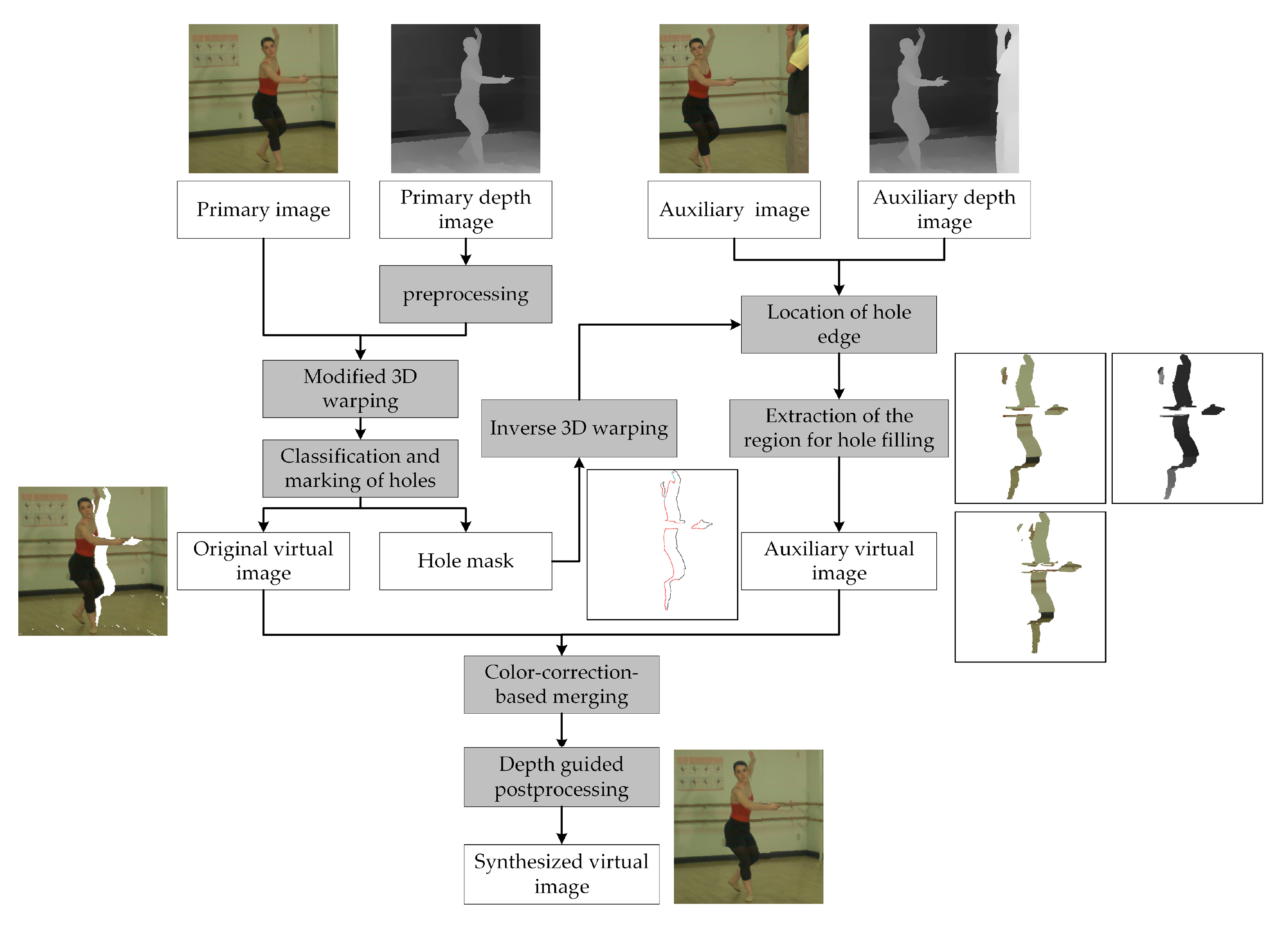
The flowchart of the proposed method is shown in Figure 3. Our framework mainly contains four parts: depth image preprocessing, asymmetric bidirectional rendering, color-correction-based merging, and depth-guided postprocessing. In the following, these approaches will be described in detail.

2.1. Depth-Image Preprocessing

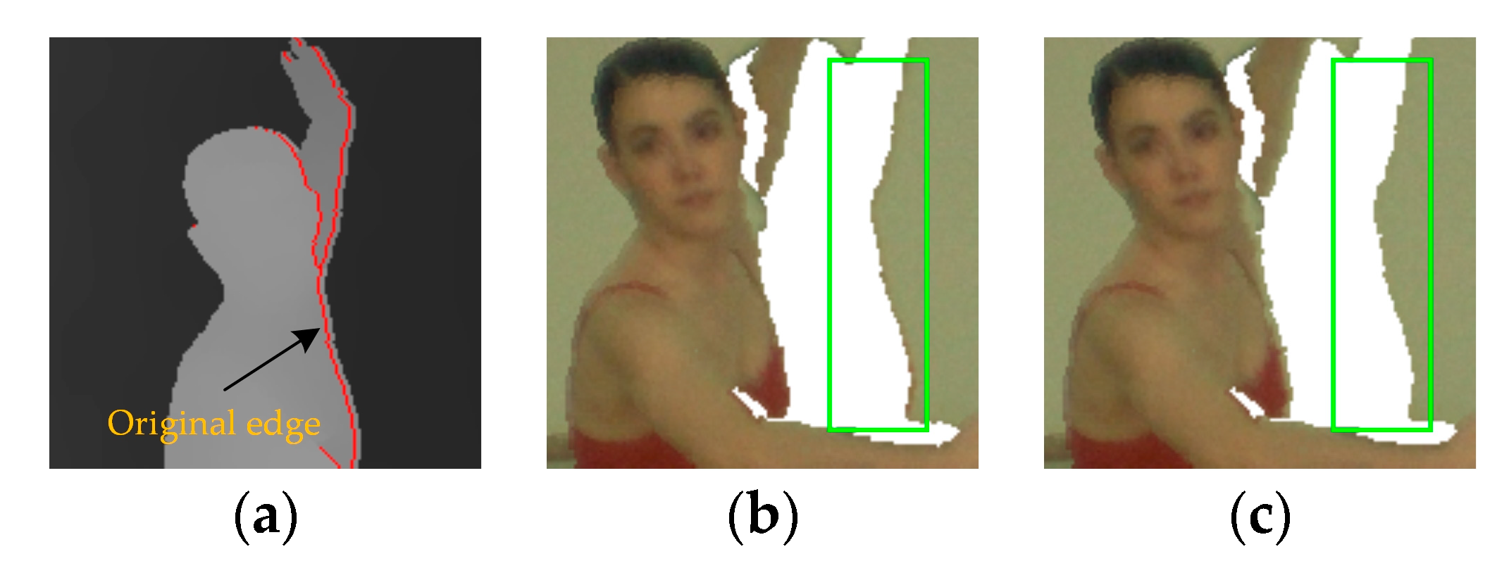
In general, disocclusions arise because of depth discontinuity between the foreground and background objects. The higher depth discontinuity leads to a larger disocclusion. As the baseline increases, the disocclusion area would increase until the entire foreground object is projected onto the new background. Therefore, accurate depth value is important for the synthesized image quality. Affected by the device accuracy and the deficient stereo matching algorithm, the depth value of the foreground edge might be coarse. This means that the edge of foreground in the depth image is mismatched with that of the color image, causing ghosts to appear around the disocclusion, as shown in Figure 4b. The mixture of foreground and background pixels on the disocclusion boundary reduces the visual quality and interferes with the background texture propagation in hole filling. Therefore, a local depth-image preprocessing approach is proposed to correct the depth value of the foreground edge.
The preprocessing process includes two steps: foreground edge detection and depth calibration. For the right synthesized image, disocclusions appear on the right side of foregrounds and located between the foreground and background. Therefore, only one side of the foreground edge needs to be extracted. Based on the principle of disocclusion generation, the relevant right foreground edge can be detected according to depth discontinuity and marked as follows:
E r = { 1 , d ( x , y ) d ( x , y + 1 ) > t 0 , otherwise ,
where d denotes the depth value; t represents the segmentation threshold and is set to 10 in the experiment. When the foreground edges that might produce ghosts are labeled, a one-dimensional template is used to process these pixels. For pixels in the template whose depth value is lower than the labeled pixel, its depth value is replaced by the labeled pixel’s depth value. This means that the edge of the foreground is extended to the background by a certain length. The size of template is set to 1 × 5 as the ghosts are usually 1–2 pixels wide. The preprocessing result is shown in Figure 4c. It can be seen that most of the ghosts are removed and projected onto the corresponding foreground edges. In the case of large baseline, ghosts may appear on both sides of the disocclusion, so similar pre-processing is necessary for the left edge of foreground. Since this process only modifies the local depth values of the image, the blurring effect would not be produced in the synthesized image. However, large holes are not obviously reduced, and further processing is necessary.

2.2. Asymmetrical Bidirectional Rendering

In the traditional bidirectional DIBR, the left and right reference views are used as input of 3D warping to synthesize the target virtual view respectively. The two synthesized images are then merged to fill the holes. In fact, a large part of area in the virtual image is commonly visible in the left and right reference views. These regions are warped twice during the bidirectional DIBR and increase the computational complexity. As the purpose of bidirectional DIBR is to obtain the missing texture of the holes in single view rendering, we reduce the computational cost by only warping the regions that are useful for hole filling. Hence, an asymmetrical bidirectional rendering approach is proposed in this paper. Based on the hole edge information in the single view rendering result, we explore the helpful textures in the auxiliary image to fill the holes and ignore those regions that may be repeatedly warped.
Set the left reference view as the primary view and the right reference view as the auxiliary view. The primary image and its processed depth image are first warped to the virtual view through the modified 3D warping [
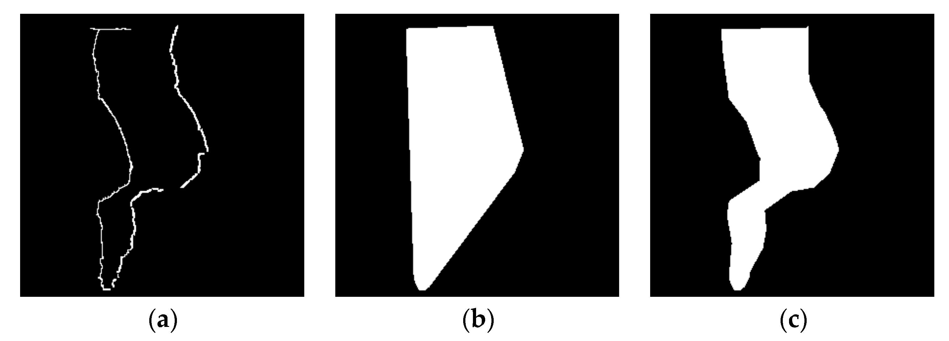
29]. During the warping process, cracks are filled by surrounding valid pixels. The overlapping pixels are sorted according to the depth value and the one with the highest depth value is selected for display. In addition, ghosts are removed in the depth preprocessing. Therefore, holes become the main problem in the synthesized image. With the movement of the viewpoint, the occlusion relationship between objects in the auxiliary view will change further compared with that in the virtual view, as shown in Figure 5. In this case, the hole in the virtual image can be effectively reduced by extracting the corresponding regions in the auxiliary image and warping them to the virtual view. Since the depth value of the hole is unknown, in this paper, we combine the valid pixels on the edge of the hole to extract the region to be warped in the auxiliary image.
The holes in the virtual image include disocclusions, OFRs, and other small holes caused by depth errors. The last type of holes usually appears inside the foreground or background objects and is characterized by the area size and edge pixel distribution. In our experiment, the hole size threshold is set to 80, and most of the pixels on the edge of the hole belong to the same type (foreground or background). As satisfactory results for filling this type of hole can be obtained by using the inpainting method, only the edges of the disocclusions and OFRs in the virtual image are marked and processed. For OFRs, since they occur on the edges of the virtual image, only part of the valid pixels on the hole edges can be determined. In order to obtain the approximate depth value of the rest, we assume that these edge pixels have the same depth values as those of the primary image when no new foreground objects appear on the edges. In this case, the depth value of all the pixels around the OFR can be determined and ready for subsequent inverse 3D warping.
For disocclusions, as they appear inside the virtual image, the valid pixels on the hole edge can be obtained directly. As shown in Figure 4c and Figure 5b, for the right-synthesized image, the right edge pixel of the disocclusion usually belongs to the background, while the left side may have both foreground and background pixels. For each row, it can be divided into two types: background–background (BG–BG) or foreground–background (FG–BG). For the former, since the background pixels around the foreground are always located at the same depth layer, the length of the disocclusion would be maintained in the auxiliary image. For the latter, as the pixels on both sides have different depth values, the distance between them will further increase in the auxiliary image, as shown in Figure 5c. So not all pixels inside the contour are helpful for hole filling. In the virtual image, the length of each disocclusion is recorded and the edge pixels of the disocclusion are classified based on the depth information. By applying the Laplacian operator to the primary depth image [30], the foreground edges of the disocclusion can be obtained and labeled as follows:
F ( x , y ) = { 1 , if ( Δ d ) w ( x , y ) < 0 0 , if ( Δ d ) w ( x , y ) > 0 , for ( x , y ) δ Ω d ,
where Δ d denotes the Laplacian of the depth image and ( Δ d ) w denotes the warped Laplacian image. δ Ω d represents the boundary of disocclusion. Based on the depth information, the edge pixels of the disocclusions and OFRs are back-warped into the auxiliary image, so the associated pixels can be located.
Based on the marked pixels through inverse 3D warping, the regions for hole filling are extracted in the auxiliary image, as shown in Figure 5c. For the disocclusion, starting from the right background edge, we extend to the left in the horizontal direction and mark the adjacent pixels as the selected pixels for warping. The length of the extension depends on the category of the left edge pixel. For BG–BG disocclusion, all the pixels between the left and right edges are selected. But for FG–BG disocclusion, the pixels of the hole length are selected for warping. As for the OFRs, since the edge pixels are located in the same depth layer, the selected pixels can be determined by extracting the pixels inside the contour. In this process, convex or concave hull extraction is optional. The result in Figure 6 shows that, for certain applications, the convex hull does not represent well the boundaries of a given set of points. The concept of alpha-shape is introduced as a solution to this problem, and other solutions, such as crust algorithms are also proposed. However, most of the proposed approaches address the reconstruction of surfaces from sets of points belonging to that surface and, therefore, are not optimized for the referred problem. Compared with the convex hull, the concave hull can better reflect the accurate shape of the contour and contain fewer selected pixels, thus reducing the computational cost. Hence, a concave hull extraction method based on K nearest neighbors [31] is applied in this paper to select the pixels for OFR filling. The K nearest neighbors extraction approach is able to deal with arbitrary sets of points by taking care of a few special cases. The “smoothness” of the computed hull can also be controlled by the user through the k parameter. Unlike the alpha-shape method, the modified K nearest neighbors approach can automatically adjust the value of k according to the distribution of the point set, instead of manually setting it based on the scene. In our experiment, the value of k starts from 3, and its value can be increased recursively in the extraction process until the given points are inside the computed polygon.
It is worth mentioning that most of the virtual views are synthesized through parallel rendering, that is, the virtual view is on the baseline formed by the primary and auxiliary views. In this way, the positional relationship between the left and right edges of the hole can be maintained in the auxiliary image, and almost all the OFRS can find the corresponding content in the auxiliary image. If there is a rotation relationship between the virtual view and reference views, the positional relationship between the edge pixels is changed after inverse 3D warping, and the extension approach mentioned above is no longer appropriate. In this case, the concave hull method is used to extract the warping regions for all types of holes to ensure that all helpful pixels are selected. In addition, to accommodate some possible depth changes and remove ghosts, the background edge of the selected regions is extended outward by using a morphological operation. Once all the selected regions are extracted, the auxiliary virtual image can be synthesized by the modified 3D warping.

2.3. Color Correction-Based Merging

Unlike single view rendering, asymmetric bidirectional rendering uses the two reference images to synthesize the target virtual image. Considering that there may be differences in brightness and color between the two images, some color-correction methods are proposed [24,32]. In these methods, two whole images are warped to the virtual view, and the ratio image is created for each virtual image. For pixels which are projected from both views, the color value of them is computed by blending the colors of two corresponding pixels. Then the ratio of these pixels are computed and inserted in the ratio image. For pixels only warped from the left or right reference image, their ratio values are obtained by computing the locally averaged ratio of the adjacent pixels. Then the color correction is performed based on the ratio image. However, in our method, only the occlusion layer in the auxiliary view is warped to the virtual view, the color correction process mentioned above is no longer applicable. Therefore, a modified merging approach based on color correction is proposed in this section. Since the virtual view is located between the left and right reference views, it can be assumed that the color difference among them is gradual. In our method, color correction is performed on the two synthesized images first, and then the contents of the auxiliary virtual image are copied to holes in the primary virtual image.
The color-correction process is performed in the Lab color space because it has a wider color gamut and better perceived uniformity. First we convert the two virtual images from Red-Green-Blue (RGB) color space to Lab color space. Compute the average L, a, and b of each image, as follows:
L ¯ i = 1 num i L i ( x , y ) , for ( x , y ) Ω i ,
a ¯ i = 1 num i a i ( x , y ) , for ( x , y ) Ω i ,
b ¯ i = 1 num i b i ( x , y ) , for ( x , y ) Ω i ,
where i = p , a represents the primary and auxiliary virtual image respectively, and num i denotes the number of valid pixels in the image. Then the overall mean of each channel is computed as:
L ¯ = L ¯ p + L ¯ a 2 , a ¯ = a ¯ p + a ¯ a 2 , b ¯ = b ¯ p + b ¯ a 2 ,
In the correction process, taking the L channel for example, the corrected result can be expressed as:
L i ( x , y ) = L ¯ L ¯ i L i ( x , y ) , for ( x , y ) Ω i , i = p , a ,
For the a and b channels, the same computation is performed. The processed images are converted from Lab color space to RGB color space. After color correction, the contents in the auxiliary virtual image are used to fill the holes. The merging process can be expressed as follows:
I ( x , y ) = { I p ( x , y ) , I p ( x , y ) Ω I a ( x , y ) , I p ( x , y ) Ω ,
where I p ( x , y ) and I a ( x , y ) are the corresponding pixels in the primary and auxiliary images, respectively, and I ( x , y ) represents the merging result. During the merging, in order to prevent the ghosts, the pixels on the background edge of the disocclusions are replaced with corresponding valid pixels in the auxiliary image, as:
I ( x , y ) = I a ( x , y ) , for ( x , y ) δ Ω d & & F ( x , y ) = 0 ,
The local comparison results of direct merging and color correction-based merging are shown in 
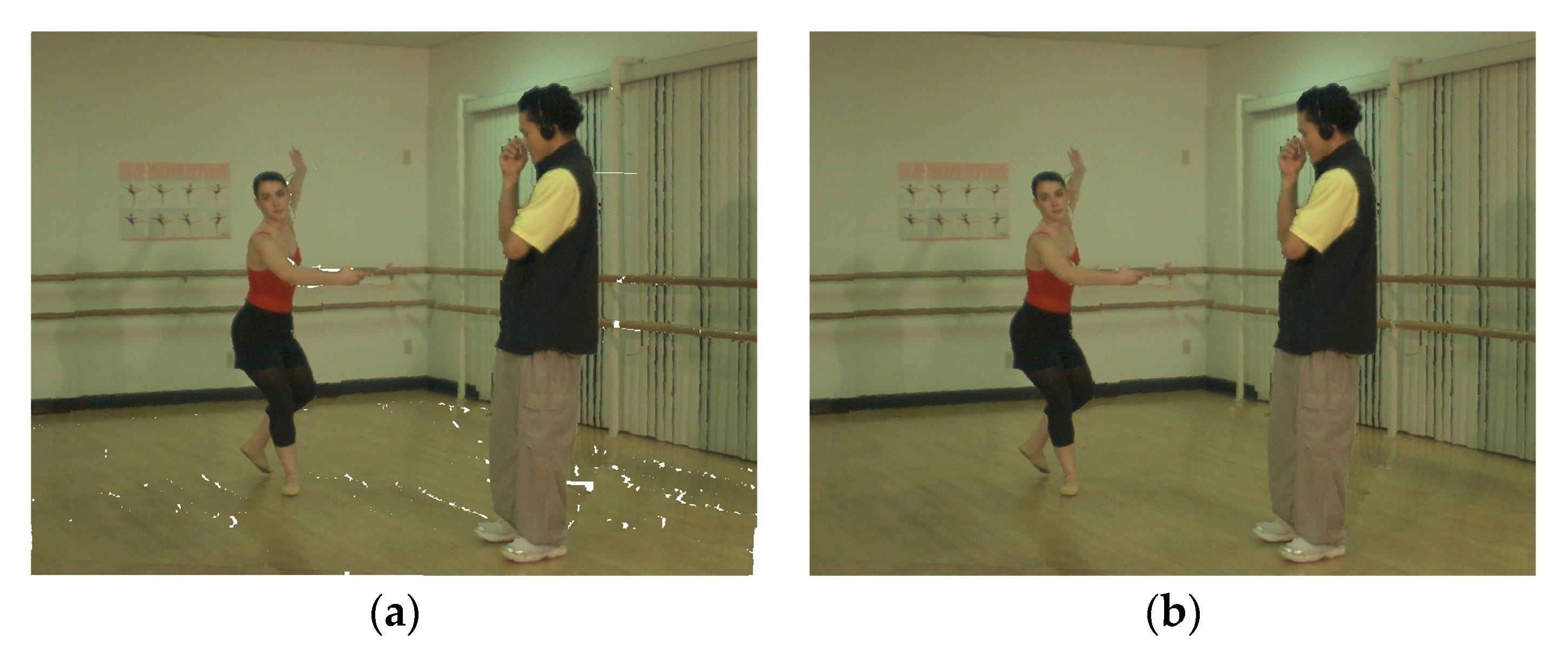
Figure 7. Compared with direct merging, the proposed merging approach reduces the abrupt changes in brightness, and makes the texture transition more natural. The overall result is shown in Figure 8a. It can be seen that the proposed asymmetric bidirectional rendering can significantly reduce the holes in the virtual image. Note that even in the bidirectional rendering, there are still holes in the virtual image because some occluded regions are not visible in both reference views. In addition, the holes caused by depth errors are also waiting to be filled.

2.4. Depth-Guided Postprocessing

This part is mainly to deal with the remaining holes after image merging. As mentioned in Section 1, Criminisi’s method [16] is not very suitable for filling these holes, because some foreground textures might be sampled to fill the disocclusions. For this task, a depth-guided inpainting method is proposed to fill the remaining holes. As the depth value can reflect that the object belongs to the foreground or background to some extent, depth information is introduced to guide the filling process.
Like Criminisi’s method [16], the depth-guided inpainting method includes three core steps: priority computation, patch matching, and priority update. The priority computation is performed on all the edge pixels of holes. For pixel p on the hole edge δ Ω , Ψ p denotes the square template centered at p . The priority of pixel p is computed as follows:
P ( p ) = [ C ( p ) · D ( p ) · Z ( p ) ] B ( p ) + ε ,
where C ( p ) and D ( p ) are the confidence term and data term as defined in [16]. Z ( p ) is depth term, which reflects the depth value of p . B ( p ) is background term, which is used to identify foreground pixels on the disocclusion edges. The two newly introduced terms are defined as follows:
Z ( p ) = d max q Ψ p Φ d ( q ) | Ψ p Φ | d max d min ,
B ( p ) = { 0 , for p δ Ω d & & F ( p ) = 1 1 , otherwise ,
where Φ denotes the source region. d max and d min are the highest and lowest non-zero depth values in the depth image. The depth term tends to give a higher priority to background pixels with lower depth value. The background term can prevent the disocclusion filling from starting from the foreground edge, even if the relevant pixels have higher confidence and texture complexity. In addition, in order to avoid the situation where the priority is equal to 0, a little parameter ε is added to Equation (10) and is set as 0.00001.
After all priorities on δ Ω are computed, the patch Ψ p ^ with the highest priority would be filled first. Considering that content with similar depth value is more suitable for filling holes in the patch, depth information is used to search for the best matching patch. The candidate patch with the smallest matching cost is represented as:
Ψ q ^ = arg min Ψ q Φ [ SSD color ( Ψ p ^ , Ψ q ) + SSD depth ( Ψ p ^ , Ψ q ) ] ,
where Φ is the search region, SSD is the sum of squared differences of the valid pixels in two patches. The content in Ψ q ^ is copied to the empty region in Ψ p ^ . After each iteration, the priority items are updated to accommodate the new valid information. The above steps are repeated until all remaining holes are filled. The filling result is shown in Figure 8b, which does not introduce the blurring effect.

3. Experimental Results and Discussion

In our experiments, the proposed method is run on a PC with Intel Core i5 (3.7 GHz) and 32 GB memory. Five public multiview video-plus-depth (MVD) sequences (“Ballet” and “Breakdancers” [33], “Dancer” [34], “Shark” [35], “Kendo” [36]) and six public still image-plus-depth sequences from the Middlebury Stereo Data Sets [37] are used to evaluate the performance of the proposed method. The parameters of the data sets are shown in Table 1. All camera parameters of the data sets are known, including internal and external parameters. For MVD sequences, the synthesized view is named after the tested sequence and projection information. For example, the image warped from view 4 and view 2 to view 3 of Ballet is named as BA3.

3.1. Evaluation of Asymmetric Bidirectional Rendering

In order to evaluate the efficiency of the proposed asymmetric bidirectional rendering approach, we use single-view rendering (SVR), bidirectional rendering (BR), and asymmetric bidirectional rendering (ABR) to synthesize the target view. The SVR uses the primary view as the reference view. Table 2 shows the size of the holes in the virtual image, which is measured by counting the number of holes’ pixels. It can be seen that most of the holes can be filled with contents in the auxiliary image. Compared with the BR that completely warps two reference images, the proposed approach only warps the regions that are helpful for hole filling. Although the hole reduction by the proposed approach is generally less than the BR, the rendering efficiency can be significantly improved, and all the remaining holes would be filled in the postprocessing. For the Breakdancers sequence, the hole size in BR3 with a large baseline is larger than BR4. Due to the lower depth quality of this sequence, hole reduction performance of the proposed approach is not as good as that on Ballet.
Figure 9 shows the partial comparison result of three rendering methods. Disocclusions and OFRs can be significantly reduced by BR and ABR. Due to the added color correction and ghost removal, the subjective visual quality of the ABR appears better than that of the BR in some cases. By selectively warping the auxiliary image, some foreground content with the wrong depth value can be effectively prevented from being warped to the disocclusions. On this basis, we compute the rendering time of three methods and the comparison results are shown in Figure 10. As the still image data is a standard parallel configuration, the image coordinates of the same 3D point in different views only have differences in horizontal coordinates, so the computational complexity is lower and the rendering speed is faster than that of MVD sequences. The BR warps the whole two images and its rendering time is about twice that of SVR. In contrast, the proposed rendering approach can achieve 97% hole reduction compared with the BR and reduce the rendering time by 37% on average. This is because the proposed approach warps the entire primary image and the local contents of the auxiliary image, thereby improving the rendering efficiency.

3.2. Subjective and Objective Evaluation of the Synthesized View

In order to evaluate the performance of the proposed method subjectively and objectively, in this section the results of the proposed method are compared with Criminisi’s method [16], Ahn’s method [18], Kao’s method [19], Li’s method [26] and Yao’s method [27]. For video sequence rendering, the results of subjective comparison between the proposed and previous methods are shown in Figure 11. In terms of visual quality, the proposed method performs better than others. In Criminisi’s method, as the depth information is not considered, the hole-filling process is performed on both the foreground and background sides, resulting in the propagation of the foreground texture, as shown in Figure 11a. In Ahn’s method, affected by the depth error, some defects appear around the foreground objects, as shown in Figure 11b. In Kao’s method, depth preprocessing is introduced to reduce ghosts, but some unexpected foreground textures are sampled to fill the disocclusion due to the mismatch of depth value, as shown in Figure 11c. In Li’s method, horizontal background extrapolation is very sensitive to artifacts, especially when both sides of the disocclusion are foreground pixels, as shown in Figure 11d. Furthermore, pixel-based extrapolation looks unnatural and is not suitable for complex textures. In Yao’s method, some unreasonable regions are produced, as shown in Figure 11e. This is because the level regularity term formed by the inverse variance cannot accurately distinguish the foreground and background, especially for the multiple depth layers. The proposed method successfully removes most of the artifacts and shows more plausible results in Figure 11f. The depth-guided postprocessing method can effectively maintain the edges of foreground objects without introducing blurring regions.
In terms of objective evaluation, peak signal-to-noise ratio (PSNR), structural similarity (SSIM) [38], feature similarity index (color) (FSIMc) [39], and visual saliency-induced index (VSI) [40] are used in our experiments to evaluate the objective quality of the synthesized views. PSNR measures the difference in pixels between two images. SSIM compares the structural similarity of the two images. FSIMc and VSI focus on the gradient and color features. The objective comparison results of the seven synthesized views by different methods are shown in Table 3 and Table 4. Higher PSNR value represents better image quality, while SSIM, FSIMc, and VSI are all normalized to 0–1. The results show that the proposed method achieves the best overall performance. taking the scenario BA3 for example, the proposed method surpasses the previous methods by 0.75–1.69dB in average PSNR. Likewise, there is evident promotion in terms of SSIM, FSIMc, and VSI.
For image sequence rendering, the subjective comparison results are shown in Figure 12. Based on the parallel configuration, most of the OFRs are filled in the merging process. In disocclusion filling, the results of the proposed method look the most likely the truth textures, while other methods contain some unrealistic contents and foreground penetration. In terms of objective evaluation, Table 5 and Table 6 show the comparison results for the still-image sequences. The proposed algorithm obtains a better evaluation on the basis of the four indicators, proving that the proposed method is robust and can adapt to the scene changes to some extent.

4. Conclusions

This paper presents a virtual view synthesis method based on asymmetric bidirectional rendering. Compared with single-view rendering, bidirectional rendering can use the effective contents in auxiliary view to fill holes in the virtual view. In order to reduce the computational cost of fully warping the two reference images, an asymmetric bidirectional rendering approach is proposed. The selected regions are extracted by marking the hole edges in the virtual image and locating them in the auxiliary image. Since only the content that is helpful for hole filling is warped, the proposed method can effectively reduce the computational complexity while maintaining the hole-filling effect. To improve the visual quality, depth-image preprocessing is introduced to correct the depth value of foreground edges and color correction is performed before image merging. In addition, for hole regions that are not visible in both reference views, a depth-guided inpainting method is proposed to fill them. The depth information is introduced to improve the priority of background pixels and maintain the contour of the foreground. The experimental results verify that the proposed method can effectively reduce the rendering complexity, and obtain satisfactory results subjectively and objectively. The method in this paper mainly focuses on the improvement of imaging quality and rendering efficiency. There is still a gap between the proposed method and the real-time rendering. In future work, we will consider combining software and hardware to further improve rendering efficiency, such as introducing Graphics Processing Unit (GPU) and Field-Programmable Gate Array (FPGA). Deep learning can provide some inspiration for disocclusion filling. It can improve the adaptability of the scene through a large number of training processes, and present more realistic results in shorter computing time. Moreover, some non-parametric algorithms have been proposed for concave hull extraction in recent years. As they do not obtain the best parameters through iteration, the efficiency and accuracy of extracting the hole layer would be improved to some extent.

Author Contributions

Conceptualization, H.L.; methodology, H.L. and Y.W.; software, H.L.; validation, H.L., H.X. and S.R.; data curation, H.L.; writing—original draft preparation, X.C. and Y.W.; writing—review and editing, X.C., H.L. and H.C.; supervision, X.C.; project administration, X.C. and Y.W. All authors have read and agreed to the published version of the manuscript.

Funding

This research was funded by the National Major Project of Scientific and Technical Supporting Programs of China during the 13th Five-year Plan Period, grant number 2017YFC0109702, 2017YFC0109901 and 2018YFC0116202.

Acknowledgments

The authors would like to thank the Interactive Visual Media Group at Microsoft Research for making the MSR 3D Video Dataset publicly available.

Conflicts of Interest

The authors declare no conflict of interest.

References

  1. Yin, S.; Dong, H.; Jiang, G.; Liu, L.; Wei, S. A Novel 2D-to-3D Video Conversion Method Using Time-Coherent Depth Maps. Sensors 2015, 15, 15246–15264. [Google Scholar] [CrossRef] [PubMed] [Green Version]
  2. Tanimoto, M. FTV: Free-viewpoint Television. Signal Process. Image Commun. 2012, 27, 555–570. [Google Scholar] [CrossRef]
  3. Tech, G.; Chen, Y.; Müller, K.; Ohm, J.-R.; Vetro, A.; Wang, Y.-K. Overview of the Multiview and 3D Extensions of High Efficiency Video Coding. IEEE Trans. Circuits Syst. Video Technol. 2015, 26, 35–49. [Google Scholar] [CrossRef] [Green Version]
  4. Tang, D.; Bouaziz, S.; Izadi, S.; Tagliasacchi, A.; Dou, M.; Lincoln, P.; Davidson, P.; Guo, K.; Taylor, J.; Fanello, S.; et al. Real-time compression and streaming of 4D performances. ACM Trans. Graph. 2018, 37, 1–11. [Google Scholar] [CrossRef] [Green Version]
  5. Rahaman, D.M.M.; Paul, M. Virtual View Synthesis for Free Viewpoint Video and Multiview Video Compression using Gaussian Mixture Modelling. IEEE Trans. Image Process. 2017, 27, 1190–1201. [Google Scholar] [CrossRef]
  6. Pucciarelli, G. Wavelet Analysis in Volcanology: The Case of Phlegrean Fields. J. Environ. Sci. Eng. A 2017, 6, 300–307. [Google Scholar]
  7. Pandey, R.; Keskin, C.; Izadi, S.; Fanello, S.; Tkach, A.; Yang, S.; Pidlypenskyi, P.; Taylor, J.; Martin-Brualla, R.; Tagliasacchi, A.; et al. Volumetric Capture of Humans With a Single RGBD Camera via Semi-Parametric Learning. In Proceedings of the 2019 IEEE/CVF Conference on Computer Vision and Pattern Recognition (CVPR), Long Beach, CA, USA, 15–20 June 2019; pp. 9701–9710. [Google Scholar]
  8. Lombardi, S.; Simon, T.; Saragih, J.; Schwartz, G.; Lehrmann, A.; Sheikh, Y. Neural volumes: Learning Dynamic Renderable Volumes from images. ACM Trans. Graph. 2019, 38, 1–14. [Google Scholar] [CrossRef] [Green Version]
  9. Fehn, C. Depth-image-based rendering (DIBR), compression and transmission for a new approach on 3D-TV. In Stereoscopic Displays and Virtual Reality Systems Xi; Woods, A.J., Merritt, J.O., Benton, S.A., Bolas, M.T., Eds.; Spie-Int Soc Optical Engineering: Bellingham, DC, USA, 2004; Volume 5291, pp. 93–104. [Google Scholar]
  10. Muddala, S.M.; Sjöström, M.; Olsson, R. Virtual view synthesis using layered depth image generation and depth-based inpainting for filling disocclusions and translucent disocclusions. J. Vis. Commun. Image Represent. 2016, 38, 351–366. [Google Scholar] [CrossRef] [Green Version]
  11. Luo, G.; Zhu, Y.; Li, Z.; Zhang, L. A Hole Filling Approach Based on Background Reconstruction for View Synthesis in 3D Video. In Proceedings of the 2016 IEEE Conference on Computer Vision and Pattern Recognition (CVPR), Las Vegas, NV, USA, 27–30 June 2016; pp. 1781–1789. [Google Scholar]
  12. Tam, W.J.; Alain, G.; Zhang, L.; Martin, T.; Renaud, R. Smoothing depth maps for improved steroscopic image quality. Optics East 2004, 5599, 162–172. [Google Scholar]
  13. Zhang, L.; Tam, W. Stereoscopic Image Generation Based on Depth Images for 3D TV. IEEE Trans. Broadcast. 2005, 51, 191–199. [Google Scholar] [CrossRef]
  14. Chen, L.-G.; Chang, Y.-L.; Lin, S.-F.; Ding, L.-F. Efficient Depth Image Based Rendering with Edge Dependent Depth Filter and Interpolation. In Proceedings of the 2005 IEEE International Conference on Multimedia and Expo, Amsterdam, The Netherlands, 6 July 2005; pp. 1314–1317. [Google Scholar]
  15. Liu, W.; Ma, L.; Qiu, B.; Cui, M.; Ding, J. An efficient depth map preprocessing method based on structure-aided domain transform smoothing for 3D view generation. PLoS ONE 2017, 12, e0175910. [Google Scholar] [CrossRef] [PubMed] [Green Version]
  16. Criminisi, A.; Perez, P.; Toyama, K. Region Filling and Object Removal by Exemplar-Based Image Inpainting. IEEE Trans. Image Process. 2004, 13, 1200–1212. [Google Scholar] [CrossRef] [PubMed]
  17. Daribo, I.; Saito, H. A Novel Inpainting-Based Layered Depth Video for 3DTV. IEEE Trans. Broadcast. 2011, 57, 533–541. [Google Scholar] [CrossRef]
  18. Ahn, I.; Kim, C. A Novel Depth-Based Virtual View Synthesis Method for Free Viewpoint Video. IEEE Trans. Broadcast. 2013, 59, 614–626. [Google Scholar] [CrossRef]
  19. Kao, C.-C. Stereoscopic image generation with depth image based rendering. Multimed. Tools Appl. 2016, 76, 12981–12999. [Google Scholar] [CrossRef]
  20. Han, D.; Chen, H.; Tu, C.; Xu, Y. View synthesis using foreground object extraction for disparity control and image inpainting. J. Vis. Commun. Image Represent. 2018, 56, 287–295. [Google Scholar] [CrossRef]
  21. De Oliveira, A.Q.; Walter, M.; Jung, C.R. An Artifact-Type Aware DIBR Method for View Synthesis. IEEE Signal Process. Lett. 2018, 25, 1705–1709. [Google Scholar] [CrossRef]
  22. Luo, G.; Zhu, Y. Foreground Removal Approach for Hole Filling in 3D Video and FVV Synthesis. IEEE Trans. Circuits Syst. Video Technol. 2017, 27, 2118–2131. [Google Scholar] [CrossRef]
  23. Li, S.; Zhu, C.; Sun, M.-T. Hole Filling With Multiple Reference Views in DIBR View Synthesis. IEEE Trans. Multimedia 2018, 20, 1948–1959. [Google Scholar] [CrossRef] [Green Version]
  24. Dziembowski, A.; Grzelka, A.; Mieloch, D.; Stankiewicz, O.; Wegner, K.; Domanski, M. Multiview synthesis —Improved view synthesis for virtual navigation. In Proceedings of the 2016 Picture Coding Symposium (PCS), Nuremberg, Germany, 4–7 December 2016; pp. 1–5. [Google Scholar]
  25. Deng, Z.; Wang, M. Reliability-Based View Synthesis for Free Viewpoint Video. Appl. Sci. 2018, 8, 823. [Google Scholar] [CrossRef] [Green Version]
  26. Li, Y.; Claesen, L.; Huang, K.; Zhao, M. A Real-Time High-Quality Complete System for Depth Image-Based Rendering on FPGA. IEEE Trans. Circuits Syst. Video Technol. 2018, 29, 1179–1193. [Google Scholar] [CrossRef]
  27. Yao, L.; Han, Y.; Li, X. Fast and high-quality virtual view synthesis from multi-view plus depth videos. Multimed. Tools Appl. 2019, 78, 19325–19340. [Google Scholar] [CrossRef]
  28. Zhu, S.; Xu, H.; Yan, L. An Improved Depth Image Based Virtual View Synthesis Method for Interactive 3D Video. IEEE Access 2019, 7, 115171–115180. [Google Scholar] [CrossRef]
  29. Chen, X.; Liang, H.; Xu, H.; Ren, S.; Cai, H.; Wang, Y. Artifact Handling Based on Depth Image for View Synthesis. Appl. Sci. 2019, 9, 1834. [Google Scholar] [CrossRef] [Green Version]
  30. Lim, H.; Kim, Y.S.; Lee, S.; Choi, O.; Kim, J.D.K.; Kim, C. Bi-layer inpainting for novel view synthesis. In Proceedings of the 2011 18th IEEE International Conference on Image Processing, Brussels, Belgium, 11–14 September 2011; pp. 1089–1092. [Google Scholar]
  31. Moreira, A.; Santos, M.Y. Concave hull: A K-NEAREST neighbours approach for the computation of the region occupied by a set of points. In Proceedings of the Insticc-Inst Syst Technologies Information Control & Communication, Setubal, Portugal, 8–11 March 2007; pp. 61–68. [Google Scholar]
  32. Dziembowski, A.; Domański, M. Adapive color correction in virtual view synthesis. In Proceedings of the 2018-3DTV-Conference: The True Vision-Capture, Transmission and Display of 3D Video (3DTV-CON), Helsinki, Finland, 3–5 June 2018; pp. 1–4. [Google Scholar]
  33. Zitnick, C.L.; Kang, S.B.; Uyttendaele, M.; Winder, S.; Szeliski, R. High-quality video view interpolation using a layered representation. ACM Trans. Graph. 2004, 23, 600–608. [Google Scholar] [CrossRef]
  34. Common Test Conditions of 3DV Core Experiments. Available online: ftp://mpeg3dv.research.nokia.com (accessed on 27 July 2013).
  35. National Institute of Information and Communications Technology. Available online: ftp://ftp.merl.com (accessed on 8 August 2013).
  36. Nagoya University Multi-View Sequences. Available online: http://www.fujii.nuee.nagoya-u.ac.jp/multiview-data/ (accessed on 24 January 2018).
  37. Scharstein, D.; Pal, C. Learning Conditional Random Fields for Stereo. In Proceedings of the 2007 IEEE Conference on Computer Vision and Pattern Recognition, Minneapolis, MN, USA, 17–22 June 2007; pp. 1–8. [Google Scholar]
  38. Wang, Z.; Bovik, A.C.; Sheikh, H.R.; Simoncelli, E.P. Image quality assessment: From error visibility to structural similarity. IEEE Trans. Image Process. 2004, 13, 600–612. [Google Scholar] [CrossRef] [Green Version]
  39. Zhang, L.; Zhang, K.; Mou, X.; Zhang, L. FSIM: A Feature Similarity Index for Image Quality Assessment. IEEE Trans. Image Process. 2011, 20, 2378–2386. [Google Scholar] [CrossRef] [Green Version]
  40. Zhang, L.; Shen, Y.; Li, H. VSI: A Visual Saliency-Induced Index for Perceptual Image Quality Assessment. IEEE Trans. Image Process. 2014, 23, 4270–4281. [Google Scholar] [CrossRef] [Green Version]
Figure 1. Illustration of the three-dimensional (3D) warping.
Applsci 10 01562 g001
Figure 2. Schematic diagram of artifact generation.
Applsci 10 01562 g002
Figure 3. Flowchart of the proposed method.
Applsci 10 01562 g003
Figure 4. Results of depth image preprocessing: (a) processed depth image; (b) warped image without depth image preprocessing; and (c) warped image with processed depth image.
Applsci 10 01562 g004
Figure 5. Extraction of the region for hole filling: (a) primary image; (b) original virtual image; and (c) extraction of the warping region in the auxiliary image.
Applsci 10 01562 g005
Figure 6. Comparison of circumscribed polygon extraction methods: (a) hole edge pixels; (b) result of convex hull; and (c) result of concave hull.
Applsci 10 01562 g006
Figure 7. Magnified results of the direct merging and color correction-based merging: (a) direct merging; and (b) color correction-based merging.
Applsci 10 01562 g007
Figure 8. Result of depth guided postprocessing: (a) merging result; and (b) postprocessing result.
Applsci 10 01562 g008
Figure 9. Comparison result of different rendering methods. Images from left to right denote the synthesized images by SVR, BR and ABR: (a) Ballet (b) Breakdancers; (c) Baby1; and (d) Aloe.
Applsci 10 01562 g009
Figure 10. Rendering time comparisons on testing data sets: (a) multiview video-plus-depth (MVD) sequences; and (b) still-image data sets.
Applsci 10 01562 g010
Figure 11. Visual quality comparison results of synthesized view for MVD sequences: (a) Criminisi’s method; (b) Ahn’s method; (c) Kao’s method; (d) Li’s method; (e) Yao’s method; (f) proposed method; and (g) ground truth.
Applsci 10 01562 g011
Figure 12. Visual quality comparison results of synthesized view for still image data sets: (a) Criminisi’s method; (b) Ahn’s method; (c) Kao’s method; (d) Li’s method; (e) Yao’s method; (f) proposed method; and (g) ground truth.
Applsci 10 01562 g012
Table 1. Parameters of data sets.
NameResolutionPrimary ViewAuxiliary ViewTarget View
Ballet1024 × 768View4View2View3
Ballet1024 × 768View6View4View5
Breakdancers1024 × 768View5View1View3
Breakdancers1024 × 768View5View3View4
Dancer1920 × 1088View1View9View5
Shark1920 × 1088View1View9View5
Kendo1024 × 768View1View5View3
Baby11240 × 1110View1View5View4
Books1390 × 1110View1View5View4
Art1390 × 1110View1View5View4
Aloe1282 × 1110View1View5View4
Reindeer1342 × 1110View1View5View4
Lampshade11300 × 1110View1View5View4
Table 2. Hole-size comparison of different methods.
DatasetHole SizeHole Reduction
SVRBRABRBRABR
BA399,1283479531196.49%94.64%
BA5108,5496255677294.24%93.76%
BR367,917655711,04990.35%83.73%
BR433,9975165819384.81%75.90%
DA550,385884310,52082.45%79.12%
SH599,857974611,63390.24%88.35%
KE331,7232338292892.63%90.77%
Baby1101,6136124625293.97%93.85%
Books148,1278298911694.40%93.84%
Art269,03318,94222,09692.96%91.79%
Aloe181,23637,69544,86879.20%75.24%
Reindeer225,95612,30213,43994.56%94.05%
Lampshade1174,33434,08545,79980.45%73.73%
Table 3. Peak signal-to-noise ratio (PSNR) and structural similarity (SSIM) comparison results for MVD sequences.
Test SequencePSNRSSIM
[16][18][19][26][27]Proposed[16][18][19][26][27]Proposed
BA331.2731.5231.6131.9832.2132.960.85770.85840.85880.86070.86110.8615
BA530.7730.8030.8631.3231.2631.410.84020.84130.84310.84390.84360.8443
BR331.0531.1231.1531.2631.2431.520.79680.79770.79790.79820.79810.7992
BR431.7531.8131.8032.5232.3032.740.81620.81790.81830.82090.82040.8219
DA537.6137.6837.7237.9938.1238.330.94030.94240.94370.94550.94590.9465
SH539.1239.4339.3839.5439.6939.810.93860.94120.94040.94310.94380.9451
KE333.1933.6433.7233.8834.0634.120.87430.87620.87660.87780.87870.8799
Table 4. Feature similarity index (color) (FSIMc) and visual saliency-induced index (VSI) comparison results for MVD sequences.
Test SequenceFSIMcVSI
[16][18][19][26][27]Proposed[16][18][19][26][27]Proposed
BA30.95390.95430.95580.95600.95660.95730.99160.99180.99190.99220.99230.9926
BA50.94910.94930.95050.95230.95100.95360.98920.98940.98950.98980.98980.9901
BR30.93570.93620.93690.93750.93720.93780.98920.98930.98950.98970.98960.9897
BR40.95840.96090.96190.96450.96370.96610.99200.99250.99270.99360.99320.9941
DA50.96510.96590.96880.97510.97490.97630.99550.99640.99680.99750.99790.9987
SH50.97270.97460.97390.97550.97640.97880.99250.99430.99370.99540.99610.9969
KE30.95380.95520.95440.95640.95710.95790.98740.98890.98860.99090.99070.9915
Table 5. PSNR and SSIM comparison results for still-image data sets.
Data Set PSNRSSIM
[16][18][19][26][27]Proposed[16][18][19][26][27]Proposed
Baby130.2330.3830.4130.5030.5230.570.87040.87100.87140.87190.87210.8724
Books25.9226.2426.2126.3326.3026.430.83800.83920.83890.84020.84050.8421
Art27.7928.3428.2728.5428.4428.730.87290.87840.87550.87800.87710.8783
Aloe25.9926.4926.4526.8426.8126.980.81490.81740.81480.82060.81920.8236
Reindeer29.0329.2229.1329.4629.3729.490.85810.85940.85910.85990.85970.8602
Lampshade132.6632.7332.7933.4133.1233.490.94130.94240.94310.94600.94570.9464
Table 6. FSIMc and VSI comparison results for still-image data sets.
Data SetFSIMcVSI
[16][18][19][26][27]Proposed[16][18][19][26][27]Proposed
Baby10.96010.96130.96160.96270.96350.96420.99100.99150.99140.99210.99270.9929
Books0.95630.95840.95790.95800.95920.96120.98720.98750.98740.98810.98840.9889
Art0.96190.96420.96450.96580.96610.96650.98710.98810.98920.98910.98980.9905
Aloe0.95380.95580.95740.96410.96370.96590.98750.98800.98790.98970.98930.9902
Reindeer0.97070.97170.97010.97240.97190.97250.99380.99410.99360.99430.99400.9943
Lampshade10.96760.96880.97060.97630.97580.97720.99400.99690.99690.99860.99750.9987

