Article

Effect of Mass-Center Position of Spinal Segment on Dynamic Performances of Quadruped Bounding with a Flexible-Articulated Spine

1
School of Mechanical and Electronic Engineering, Wuhan University of Technology, 122 Luoshi Road, Hongshan District, Wuhan 430070, China
2
China Nuclear Power Operation Technology Corporation, Ltd., Wuhan 430070, China
*
Author to whom correspondence should be addressed.
Appl. Sci. 2020, 10(4), 1491; https://doi.org/10.3390/app10041491
Submission received: 8 January 2020 / Revised: 17 February 2020 / Accepted: 17 February 2020 / Published: 21 February 2020

Abstract

:
Driven by the layout design of devices arranged on the spine of quadruped robot which has a symmetry spine with a flexible joint, we explore the effect of mass-center position of spinal segment (MCPSS) on dynamic performances of quadruped bounding. A simplified model is introduced with MCPSS set as an independent parameter. Periodically quadruped bounding motions are generated to calculate different dynamic performances related to different MCPSS at the low, medium, and high horizontal speeds, respectively. The results indicate MCPSS corresponding to the optimal or suboptimal dynamic performances mainly gather at two positions: the hip joint and the geometric center of spinal segment. MCPSS near the hip joint leads to the largest stride period, stride length, and spinal oscillation-margin at all speeds. The smallest duty factor can also be obtained at the medium and high speeds. These improved inherent characteristics offer advantages in leg-orientation control and fast movement effectively. MCPSS near the geometric center of spinal segment brings the best self-stability, the smallest mass-center vertical fluctuation, and the smallest maximum foot-end force at all speeds, which should greatly enhance resistances to vertical jitters and reduce torque-demands of joint-drivers. This study should give useful suggestions to robot designs in reality.

1. Introduction

The previous researches have revealed that some terrestrial quadruped mammals adopt their flexible spines to improve motion performances, especially in asymmetrical gait [1,2]. For example, the spinal motion can increase stride length, provide auxiliary power to legs, improve energy efficiency, etc. Inspired by these biomechanical discoveries, the flexible spines are introduced into quadruped robots such as Planar-quadruped [3], Kitty-robot [4], MIT-cheetah I [5,6], Bobcat-robot [7], Lynx-robot [8], etc. Among them, the quadruped robot with a flexible-articulated spine is a special type because its easiness for modeling and calculating.
As we all know, the simplified model is an effective tool for theoretical research without a fine platform. The simplified model of a quadruped robot with a flexible-articulated spine is introduced to analyze the effect of the spine on performances of quadruped motion popularly. For example, Wei et al. [9] compared two quadruped models, one with a rigid spine and another with a passively flexible-articulated spine, to find that the flexible spine is superior to a rigid spine in decreasing the mass-center vertical fluctuation, foot-end force and energy consumption. Callen Fisher et al. [10] adopted sagittal simplified models of quadruped robot to compare different spine morphologies in terms of stride average acceleration, and it is found that the articulated spine is not superior to the prismatic spine with respect to this performance. Yesilevskiy and Remy [11] adopted similar models to support that the flexible-articulated spine can increase maximum possible speed and improve energy efficiency for quadruped robot in asymmetrical gaits.
In addition, some researches show that the spinal structural parameters are important factors of spinal benefits to dynamic performances. Cao and Poulakakis [12] established a passively quadruped model in dimensionless form and pointed out that the self-stability of quadruped bounding benefits from certain stiffness combinations of leg and spine, larger moment-inertia about the mass-center of spinal segment and longer spinal segment. Their subsequent study [13] has further shown that the increased spinal stiffness leads to a higher stride frequency, and the larger ratio of spinal mass to the total mass of quadruped robot benefits to higher horizontal speed and energy efficiency. Nie et al. [14] found that the appropriately decreasing ratio of front body-mass to rear body-mass can enhance the locomotion performance of quadruped bounding with an articulated spine without scarfing motion stability. Phan et al. [15] discovered that the asymmetric segmented spine helps the quadruped robot run more efficiently than the symmetric segmented spine. Pouya et al. [16] compared two quadruped models, one with a passive spine and another with an active spine, to find that decreasing spinal stiffness benefits to higher energy efficiency only when the spine is actuated.
To the best of the author’s knowledge, the mass-center position of spinal segment (MCPSS, not the mass-center position of the whole spine) was preset as constant in almost all researches on quadruped robots with a flexible-articulated spine. However, different arrangements of devices such as actuators, batteries, and transmission components on spinal segments can lead to different MCPSS, which would change the natural behavior and dynamics performance of this type of quadruped robots. Zou’s research [17] indicates that the mass-center position of the spine has important influences on dynamic performances of quadruped bounding. Although the quadruped model in his study has a rigid spine, the result shows that the mass-center position of the spine is a very important factor to dynamic performances of quadruped bounding. Nie’s study [14] obtains similar discoveries in quadruped bounding with a flexible-articulated spine. Moreover, inspired by nature, where neither of the anterior and posterior spinal segment of almost terrestrially quadruped mammals is evenly mass-distributed, we guess that MCPSS may also have important influences on dynamic performances. In addition, the effect of MCPSS on dynamic performances of quadruped bounding is still lacking of research at present.
The contributions of this study are exploring the effect of MCPSS on dynamic performances of the quadruped bounding with a flexible-articulated spine. A large number of periodic bounding motions with different MCPSS are generated at the low, medium and high horizontal speeds, respectively. The dynamic performances calculated subsequently are to be related to different MCPSS. The analyses consider the resulting diversity due to different horizontal speeds. This study should provide suggestions to the layout design of devices arranged on spinal segments of quadruped robots in reality. The remainder of this paper is organized as follows. The simplified model and dynamics model of quadruped bounding in the dimensionless form are established in Section 2. The periodically quadruped bounding with different MCPSS at different horizontal speeds are generated in Section 3. The relations between MCPSS with dynamic performances are analyzed in Section 4. The paper is discussed and concluded in Section 5.

2. Quadruped Bounding Model with a Flexible-Articulated Spine

To explore the effect of MCPSS on dynamic performances, the quadruped bounding model is established mathematically based on a simplified sagittal-plane model with a flexible-articulated spine. MCPSS is set as an independent structural parameter in this model. In addition, in order to improve the calculating efficiency and result-universality of this study, all parameters are normalized in dimensionless form.

2.1. Sagittal Simplified Model

A quadruped bounding model with a flexible-articulated spine is introduced in the sagittal plane, as shown in Figure 1. In this model, the spine consists of two equal rigid segments: one anterior segment and another posterior segment. The two rigid spinal segments are connected by a massless linear-rotational spring which intends to introduce flexibility in the spine, and MCPSS is set as an independent structural parameter. In addition, three hypotheses are set up. The first is that the two legs are replaced by the same massless linear springs; the second is that there are no slippages of legs in contact with the ground; the third is that no inputs and controls are added, that is, the model is passive. Despite the simplicity of this model, this model is capable of capturing the natural behaviors of quadruped bounding and is advantageous to reflect the effect of structural characteristics on dynamic performances centrally [12].
For every leg, the stiffness and nominal length of leg are denoted by k l and l 0 , respectively. The anterior and posterior legs are configured by the real-time length l a , l p , the real-time angle γ a , γ p with respect to the ground, and the real-time angle φ a , φ p with respect to the corresponding spinal segment, respectively. For every spinal segment, the stiffness, the total length, the mass, and the moment of inertia about its mass-center are denoted by k s , d , m , and J c , respectively. The pitch angles of the anterior and posterior spinal segments are denoted by θ a and θ p , respectively. The spinal joint is located by coordinates x s and z s . In addition, the distance between the mass-center of every spinal segment with the spinal joint is d c . MCPSS is defined as the ratio of d c to d , and denoted by λ . So
λ = d c / d 0 d c d , 0 < d
where it can be seen that λ [ 0 , 1 ] in this study. In particular, values 0, 0.5, 1 of λ correspond to MCPSS being at the spinal joint, the geometric center of spinal segment, and the hip joint, respectively.

2.2. Hybrid Dynamics of Quadruped Bounding

Only a suitable combination of movements of continuous states and the renewals of discrete states can generate periodically quadruped bounding. The hybrid dynamics of quadruped bounding are shown in this section, which is presented by the dynamics equation of continuous states and event-function-based renewal formulas of discrete states together.

2.2.1. Dynamics Equation of Continuous States

The modeling method proposed by Remy [18] is adopted to obtain a uniform dynamics equation of continuous states. In this model, the continuous states chosen as generalized coordinates are the same and are denoted by q c o n , whatever the phase of quadruped bounding is. In this study, q c o n = [ x s , z s , θ a , θ p ] .
The dynamics equation of continuous states is established completely according to the phase transitions of the leg shown in Figure 2 [18,19], but not the phase transitions of the quadruped robot [12], which makes the dynamics calculation more simple and convenient. Based on the Newton–Euler method, the dynamics equation of continuous states in state space can be presented as
M ( q c o n ) q ¨ c o n + V ( q c o n , q ˙ c o n ) q ˙ c o n + G ( q c o n ) = F l ( q c o n )
where M , V , G , and F l represent mass matrix, vector of centrifugal force and Coriolis force, vector of gravitational forces, and vector of foot forces, respectively. In this model, the continuous states are denoted by Q c o n
Q c o n = [ q c o n , q ˙ c o n ]

2.2.2. Trigger of Events and Renewal of Discrete states

That the trigger of events alternates with the renewal of related discrete states constantly is an important characteristic of the quadruped motion. Based on Figure 2, the event functions and renewal formulas of discrete states of quadruped bounding are to be presented in this section.
  • Trigger of the touchdown-event and renewal of related discrete states
When the vertical distance between foot-end with ground decreases to zero monotonously, the touchdown-event is triggered. The touchdown-event functions of the anterior and posterior legs are denoted by f a 01 and f p 01 , respectively. The corresponding trigger condition can be expressed as
f i 01 = 0 ,   f ˙ i 01 < 0 ,   p h a s e i = 1 , i [ a , p ] ,
where
f a 01 = ( z s + d sin ( θ a ) ) l 0 cos ( γ a t d )
f p 01 = ( z s d sin ( θ p ) ) l 0 cos ( γ p t d )
where γ a t d and γ p t d are the touchdown angle of the anterior and posterior legs, respectively. p h a s e a and p h a s e p denote the current phase of the anterior and posterior legs, respectively.
The related discrete states including the phase and the horizontal coordinate of touchdown position of leg renew at the moment the touchdown event is triggered. The renewal formulas corresponding to the anterior and posterior legs are
p h a s e a 2 ,   x a t d x s + d cos ( θ a ) + l 0 sin ( γ a t d )
p h a s e p 2 ,   x p t d x s d cos ( θ p ) + l 0 sin ( γ p t d )
respectively, where x a t d and x p t d denote the horizontal coordinate of touchdown position of anterior and posterior legs, respectively. The symbol ‘ ’ represents the transition of discrete states, and the following are all the same.
  • Trigger of liftoff-event and renewal of related discrete states
When the gap between the current length with the nominal length of a leg increases to zero monotonously, the liftoff-event is triggered. The liftoff-event functions of the anterior and posterior legs are denoted by f a 02 and f p 02 , respectively. The corresponding trigger condition can be expressed as
f i 02 = 0 ,   f ˙ i 02 > 0 ,   p h a s e i = 2 ,   i [ a , p ]
where
f a 02 = ( z s + d sin ( θ a ) ) / cos ( γ a ) l 0
f p 02 = ( z s d sin ( θ p ) ) / cos ( γ p ) l 0
The related discrete states including the phase and the termination time of following climbout phase of leg renew at the moment the liftoff event is triggered. The renewal formulas corresponding to anterior and posterior leg are
p h a s e a 3 ,   t s a t r a + Δ t r
p h a s e p 3 ,   t s p t r p + Δ t r
respectively, where t s a and t s p are the termination times of climbout phase of the anterior and posterior legs, respectively. t r a and t r p are the termination times of stance phase of the anterior and posterior legs, respectively. Δ t r is the duration of climbout phase of every leg.
• Trigger of flying-event and renewal of related discrete states
When the gap between the current time and the termination time of climbout phase of a leg increases to zero monotonously, the flying-event is triggered. The flying-event functions of the anterior and posterior legs are denoted by f a 03 and f p 03 , respectively. The corresponding trigger condition can be presented as
f i 03 = 0 ,   f ˙ i 03 > 0 ,   p h a s e i = 3 ,   i [ a , p ]
where
f a 03 = t t s a
f p 03 = t t s p
where t is the real time.
The related discrete state including the phase of leg renews at the moment the flying-event is triggered. The renewal formulas corresponding to the anterior and posterior legs, respectively, are
p h a s e a 1
p h a s e p 1

2.3. Parameters Normalization in a Dimensionless Form

In this study, the system parameters include structural parameters, timing parameter, motion states and their derivatives to time. These parameters are normalized in a dimensionless form to reduce parameter dimension and make the target results available to quadruped robots with different sizes. The total length L ( L = 2 d ), the total mass M ( M = 2 m ) of the spine, and the acceleration of gravity g are selected as the geometric scale, the mass scale, and the acceleration scale of gravity, respectively. The timing scale can be derived as τ = L / g . In this paper, all the parameters in a dimensionless form can be identified by the superscript ‘*’. For example, m * , d * , x s * , x ˙ s * , x ¨ s * , and t r a * are the dimensionless form of m, d , x s , x ˙ s , x ¨ s , and t r a , respectively.

3. Periodically Quadruped Bounding with Different MCPSS

To explore the effect of MCPSS on dynamic performances, a large number of periodically quadruped bounding with different MCPSS need to be obtained at different horizontal speeds respectively. It is worth noting that adding the conditions of different horizontal speeds aims to consider the possibly greatly potential diversity of target result due to different horizontal speeds. At first, the combination of the structural parameters including m * , d * , J c * , l 0 * , k s * , k l * , and total mechanical energy E * should be preset separately at different horizontal speeds. However, m * , d * , J c * , and l 0 * are given in this paper, but the combination of k s * , k l * , and E * need to be determined separately at different horizontal speeds. The determination is also based on the generation method of periodically quadruped bounding with k s * , k l * , and E * set as parameters to be optimized.

3.1. Generation Method of Periodically Quadruped Bounding

Based on the generation method of periodically quadruped bounding proposed by Remy et al. [16], the periodically quadruped bounding with a flexible-articulated spine can be generated. In this method, the parameters preset and the parameters to be optimized in a dimensionless form are denoted by X p r e * and X o p t * , respectively. The solution of dynamics equations of quadruped bounding is the main core. The periodicity of quadruped bounding can be judged by adopting the Poincare mapping [20], and the Poincare section in this study is selected at the moment the posterior leg just lifts off the ground. The relationship of continuous states of two continuous periods at the Poincare section can be expressed by
k + 1 Q c o n * = P ( k Q c o n * )
where P represents the Poincare mapping function. The periodically quadruped bounding is generated only if the motion states of two continuous periods at the Poincare section are the same, that is,
k Q c o n * P ( k Q c o n * ) = 0
The aforementioned generation of periodically quadruped bounding can be implemented through numerical optimization which adopts the function named ode45 and Particle Swarm Optimization (PSO) [21] in MATLAB.

3.2. Determination of Preset Parameters

In this paper, the remaining preset parameters including k s * , k l * , E * are determined based on the generation of periodically quadruped bounding. In this optimization work,
X p r e * = [ m * , d * , λ , J c * , l 0 * , x ˙ s i n * ]
X o p t * = [ k s * , k l * , γ a t d * , γ p t d * , Δ t r * , x s i n * , z s i n * , θ a i n * , θ p i n * , z ˙ s i n * , θ ˙ a i n * , θ ˙ p i n * ]
It is worth noting that MCPSS is fixed at the geometric center of spinal segment ( d c * = 0.25 , λ = 0.5 ) in this part of work. In addition, different horizontal speeds of the spinal joint are adopted to distinguish different horizontal speeds of the quadruped robot, which is feasible because the larger horizontal speed of the quadruped robot corresponds to the larger horizontal speed of spinal joint approximately in the Poincare section. In this paper, the numerical values of x ˙ s i n * constitute an arithmetic series which is from 1.8 to 3.0 with a tolerance of 0.1. E * can be obtained by the formula
E = m * x s * + 2 m * g * z s * + 1 2 J c * ( ( θ ˙ a * ) 2 + ( θ ˙ p * ) 2 ) + m * g * ( sin θ a * θ p * ) + 1 2 k s * ( θ a * θ p * ) 2 1 2 m * d c * ( θ ˙ p * sin θ p * θ ˙ a * sin θ a * )
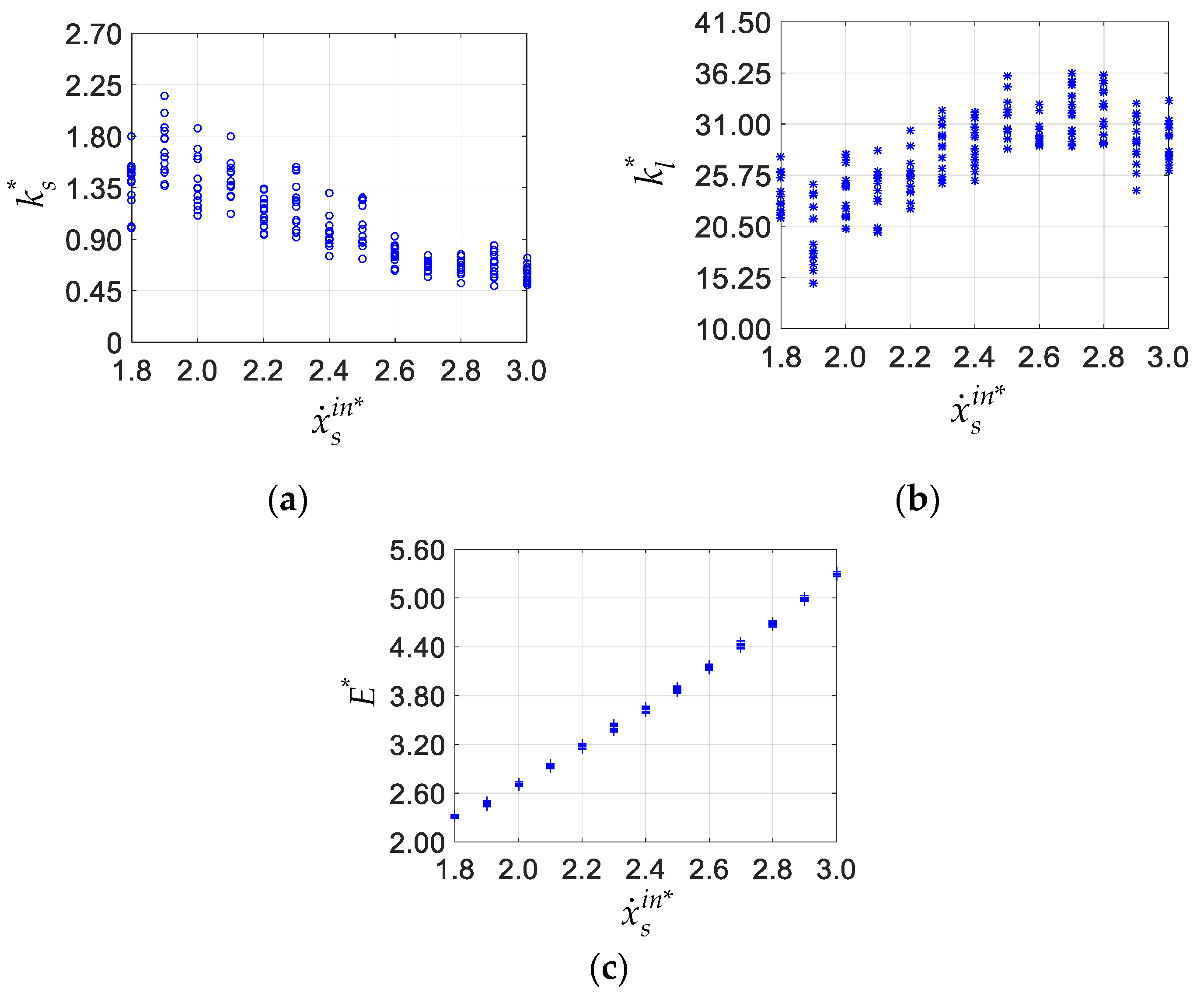
The given values of m * , d * , J c * , and l 0 * are shown in Table 1. Through optimization calculation, a large number of periodically quadruped bounding are generated at different horizontal speeds respectively. Different combinations of k s * , k l * , and E * obtained are shown in Figure 3. However, only one combination of k s * , k l * , and E * is needed with respect to every horizontal speed in the following target work. In this paper, the combination with the best self-stability is chosen. For the following target work, the values 1.8, 2.4, and 3.0 are chosen to represent the low, medium, and high horizontal speeds, respectively. The corresponding combinations of k s * , k l * , and E * are shown in Table 2.

3.3. Periodically Quadruped Bounding with Ddifferent MCPSS

To generate the periodically quadruped bounding with different MCPSS, the other structural parameters and the total mechanical energy are preset as fixed values. The combination of the stiffness of leg, the stiffness of spinal joint and the total mechanical energy are given in Table 2 at the low (1.8), medium (2.4), and high (3.0) horizontal speeds, respectively. To the optimization itself, the parameters preset and to be optimized are
X p r e * = [ m * , d * , λ , J c * , l 0 * , k s * , k l * , x ˙ s i n * ]
X o p t * = [ γ a t d * , γ p t d * , Δ t r * , x s i n * , θ a i n * , θ p i n * , z ˙ s i n * , θ ˙ a i n * , θ ˙ p i n * ]
where z s i n * is not included in X o p t * because of the supplementary constraint as Equation (23). The values of λ constitute an arithmetic series from 0 to 1 with a tolerance of 0.1, which represents MCPSS varies from the spinal joint to hip joint. After the parameters to be optimized ( X o p t * ) are obtained, all the initial conditions including the continuous and discrete states, with the structural parameters, can generate a periodically quadruped bounding.
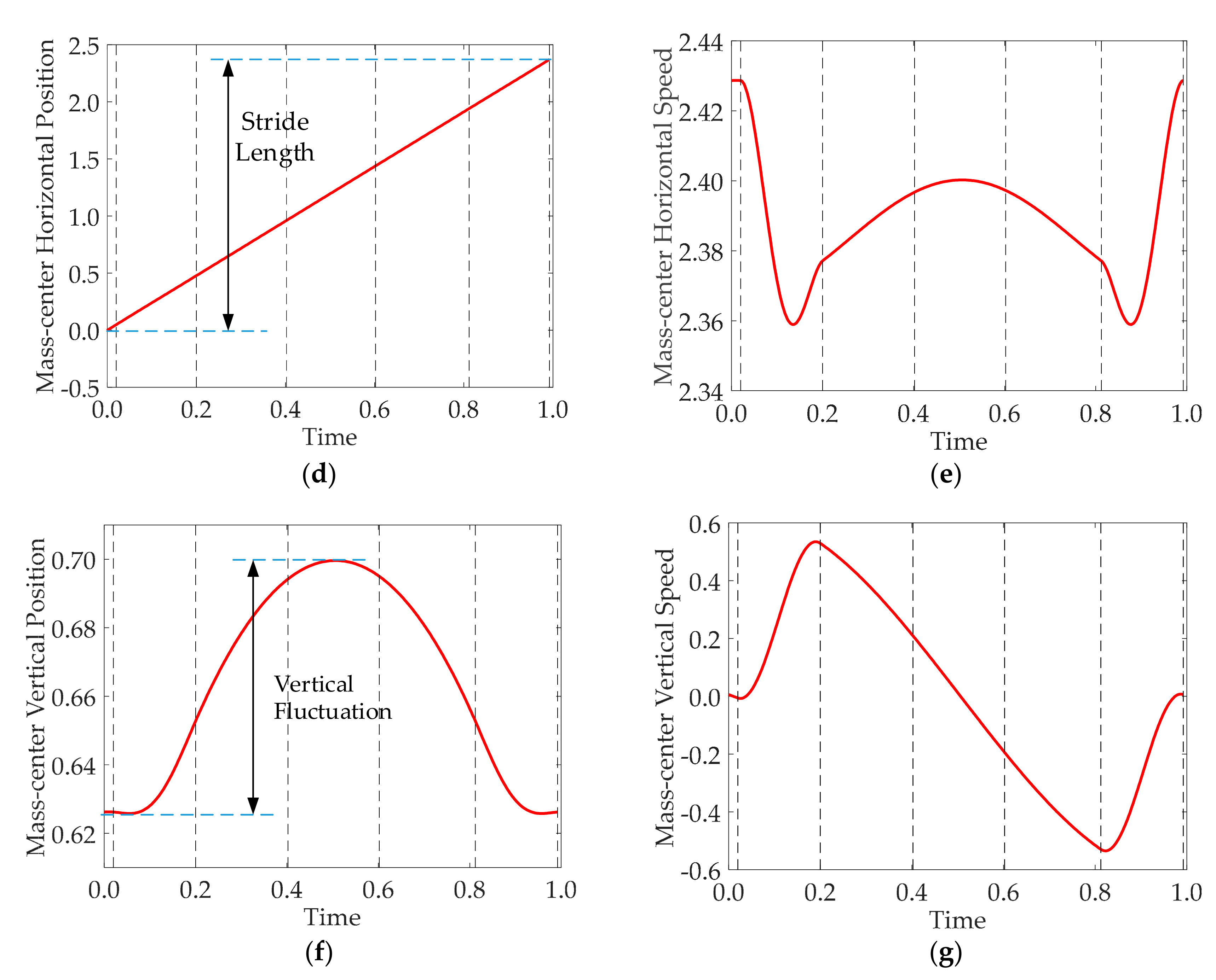
An instance of periodically quadruped bounding in one whole period with ‘ λ = 0.5 ’ and ’ x ˙ s i n * = 2.4 ’ is shown in Figure 4. The snapshots of quadruped bounding in the whole period are shown in Figure 4a. These snapshots correspond to the triggers of leg events. That is, the quadruped bounding motion experiences these events successively: liftoff of anterior legs (a), touchdown of posterior legs (b), liftoff of posterior legs (c), flying of anterior legs (d), flying of posterior leg (e), touchdown of anterior (f), and liftoff of anterior legs (g). Through further calculations, the evolution of the spinal pitch angles, the foot-end force, and the position and speed of the mass center can be obtained, as shown in Figure 4b–g.
In this instance of periodically quadruped bounding, the pitch angle of the spinal joint is found to be about 0, when the anterior legs touchdown the ground or the posterior legs liftoff the ground, as shown in Figure 4b. This reveals that almost all the spinal elastic potential energy is released to absorb the impact energy between the anterior legs with the ground, or make the quadruped robot obtain the maximum forward speed after the posterior legs lift off the ground. Probably due to the symmetrical structure of the quadruped bounding model about the spinal joint, the foot-end force of the anterior and posterior legs varies same, as shown in Figure 4c, except their touchdown and liftoff times are different. The mass center of the quadruped robot surely moves forward, but its vertical position increases first and then decreases periodically, as shown in Figure 4d,f, respectively. The mass center undergoes two horizontal accelerations and decelerations, most likely due to the separate interaction between the anterior and posterior legs with the ground, with the coordination of the spinal flexion and extension, as shown in Figure 4e. The mass center fluctuates vertically with one single peak and valley nearly, and a special phenomenon also present small jitters before and after the posterior legs touchdown the ground. It is very sure that different initial conditions will generate different instances of quadruped bounding motions. At least ten instances are obtained at every MCPSS at the low, medium, and high horizontal speeds, respectively.

4. Results and Discussion

A large number of the periodically quadruped bounding motions with different MCPSS are generated at the low, medium, and high horizontal speeds, respectively. Then, large amounts data about dynamic performances which includes the motion stability, gait characteristics, the spinal oscillation, the energy distribution of the total mechanical energy, the mass-center vertical fluctuation and the maximum foot-end force can be quantified numerically. Subsequently, the relation between every dynamic performance with different MCPSS can be analyzed at different horizontal speeds. The analyses are hoped to capture the obvious advantages and disadvantages of dynamic performances at certain MCPSS, and it is best to form a certain collection of some similar performances.

4.1. Motion Stability

The motion stability analyzed in this study refers to the method ever adopted by Cao and Poulakakis [12]. When the fixed point Q ^ c o n * (the generated continuous states at the Poincare section) is subjected to a small disturbance at the Poincare section, the increments of the continuous states k Q c o n * and k + 1 Q c o n * (the Left superscripts ‘k’ and ‘k+1’ correspond to the kth and (k+1)th period, respectively) to the fixed point Q ^ c o n * can be related by
k + 1 Q c o n * Q ^ c o n * = A ( k Q c o n * Q ^ c o n * )
at the Poincare section, where A is the Poincare matrix. The maximum eigenvalue ρ ( A ) of the matrix A is calculated to reflect the motion stability. The smaller ρ ( A ) is, the more stable the quadruped bounding is. It is worth noting that this motion stability reflects self-stability in fact because of no external inputs and controls in all joints of this model. As mentioned earlier, this simplified model is used to capture the motion stability of the natural behavior of quadruped bounding.
The effect of MCPSS on the motion stability is presented at the low, medium and high horizontal speeds, respectively, as shown in Figure 5. It can be seen that the quadruped bounding shows better stability with faster horizontal speed. The stability gets worsen as MCPSS moves from the geometric center of spinal segment ( λ = 0.5 ) to hip joint ( λ = 1 ) at all speeds, and the worsen trend increases gradually obviously. Moreover, when MCPSS moves from the spinal joint ( λ = 0 ) to the geometric center of spinal segment, the motion stability remains a small change at the medium or high speeds, but the stability gets better evidently at the low speed. That is, the motion stability corresponding to MCPSS being at the geometric center of spinal segment can be used as the optimal or suboptimal solution at all speeds.

4.2. Gait Characteristics

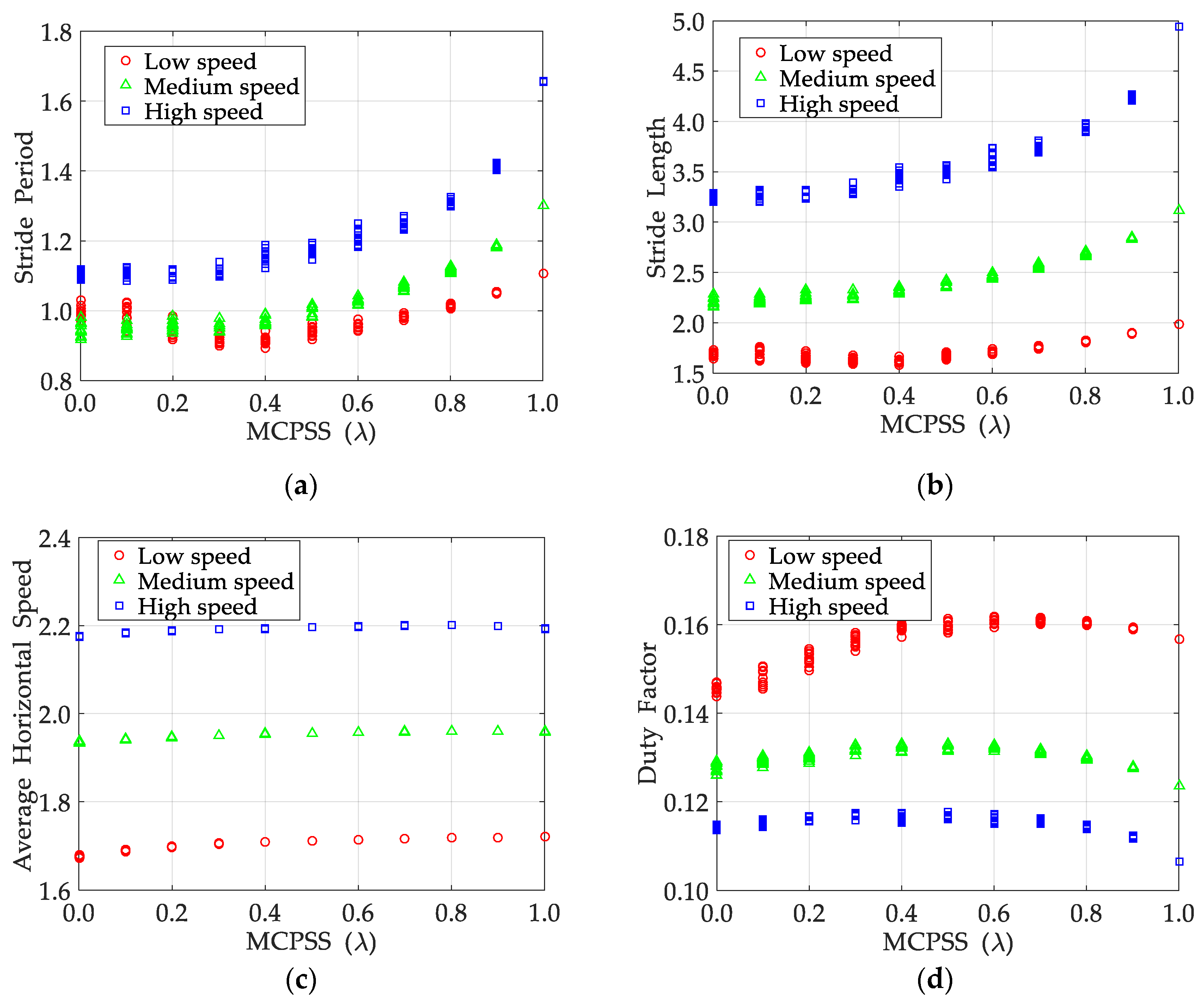
The effect of MCPSS on the gait characteristics are investigated in this section. The gait characteristics include the stride period, the stride length, the average horizontal speed, and the duty factor in this study. The relation of every gait characteristic with MCPSS is analyzed at the low, medium, and high horizontal speeds, respectively.
The stride period is the duration of a complete period. It can be obtained by calculating the time difference between two continuous periods at the Poincare section, as shown in Figure 6a. When the horizontal speed is low, the stride period gets shorter first until λ = 0.4 and then increases, and the changes remain small. When the horizontal speed is medium and high, the shorter distance between MCPSS and hip joint causes a monotonic increase of stride period, and this trend gets very obviously when MCPSS is near the hip joint. For example, the stride period as MCPSS being at the hip joint is 44%, 28%, and 15% than that as MCPSS being at the geometric center of spinal segment at the high, medium, and low horizontal speeds, respectively. These so longer stride periods are more beneficial to leg-orientation control for the following step.
The stride length can be calculated by the horizontal movement distance of the spinal joint in a whole period. It can be seen from Figure 6b that the stride length keeps increasing as MCPSS moves from the spinal joint towards the hip joint, and the increasing trend gets more obviously gradually. In particular, the effect of MCPSS on the stride length becomes more significant as speed increases. For example, stride length corresponding to MCPSS being at the hip joint is 14.8%, 36.24%, and 50.32% than that with MCPSS being at the spinal joint at the low, medium, and high speeds, respectively. The stride length corresponding to MCPSS being at the hip joint is 1%, 6%, and 8.5% than that with MCPSS being at the spinal joint at the low, medium and high speeds, respectively. Adjusting MCPSS towards the hip joint is favorable for faster quadruped bounding.
The average horizontal speed can be obtained easily by dividing stride length and stride period, as shown in Figure 6c. It can be found that the average horizontal speed maintains a small increase as MCPSS moves from the spinal joint towards the hip joint at all speeds. The average horizontal speed corresponding to MCPSS being at the hip joint is about 7.2%, 2.7%, and 1.2% higher than that corresponding to MCPSS being at the spinal joint at the low, medium and high speeds, respectively. Although the stride length increases obviously, but the increasing amount of the average horizontal speed is always small on the whole, which is probably due to the obviously increased stride period. These findings indicate that the effect has a light influence on the average horizontal speed of quadruped bounding at all speeds.
The duty factor is defined as the ratio of the duration of leg contacting with the ground to the whole stride period. The smaller duty factor is more beneficial to faster motion and better acceleration performance. Figure 6d shows the effect of MCPSS on the duty factor of leg at the low, medium, and high horizontal speeds, respectively. The anterior and posterior legs are found to have the same duty factor due to the asymmetric structure of the quadruped robot. So, only the effect of MCPSS on the anterior leg is presented. It can be seen that the duty factor with respect to different MCPSS show a single peak at all speeds. MCPSS being at peaks of duty factor are all near the geometric center of spinal segment. In particular, considering the duty factor for faster quadruped bounding and better acceleration characteristics, the MCPSS being near the spinal joint is a better choice at low speed, but the MCPSS being near the hip joint at medium and high speeds.
Based on these analyses, it can be seen that horizontal speed is an important factor in the effect of MCPSS on duty dynamics, such as the different optimal MCPSS at different speeds. Moreover, on the whole, MCPSS being near the hip joint is beneficial to leg-orientation control and faster movement, especially when quadruped bounding is fast relatively.

4.3. Spinal Oscillation

The spinal oscillation is an important characteristic of quadruped bounding with a flexible-articulated spine. It is defined as the positive difference between the maximum and minimum spinal pitch angles. It has been known that MCPSS influences greatly on gait characteristics such as stride period, stride length and duty factor. The spinal motion is coupled with the gait characteristics, so the spinal oscillation should be influenced obviously by MCPSS.
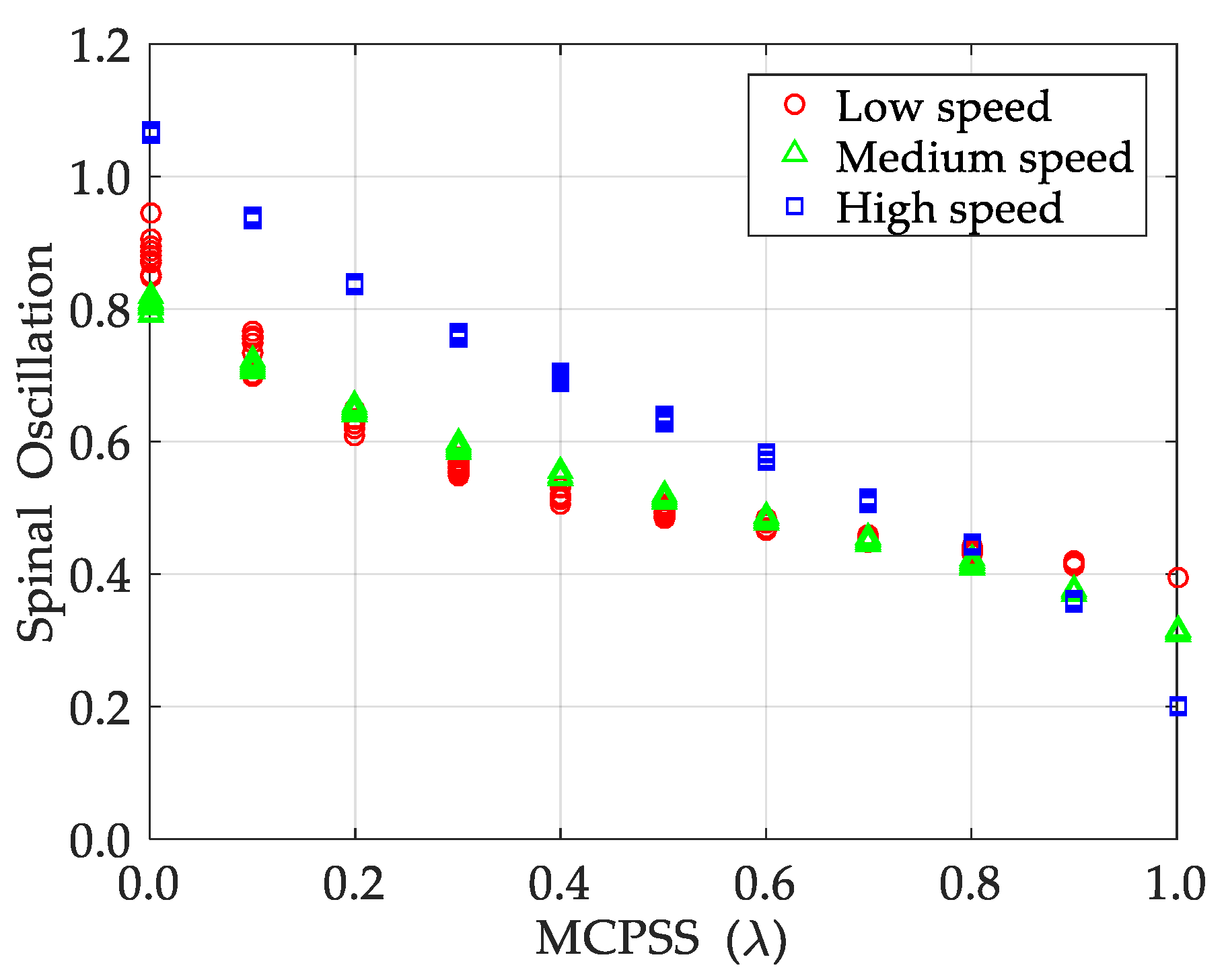
The relation between the spinal oscillation with MCPSS is shown in Figure 7 at the low, medium, and high horizontal speeds, respectively. It can be seen that the spinal oscillation decreases monotonously as MCPSS moves from the spinal joint towards the hip joint at all speeds. In particular, for quadruped bounding at low and medium speeds, the decreasing trend of spinal oscillation becomes slower gradually, especially after MCPSS crosses over the geometric center of spinal segment. For quadruped bounding at high speed, the decreasing trend maintains almost constantly. Based on these finds, it can be obtained that the spinal oscillation with respect to MCPSS being at the spinal joint and the hip joint is about 1.07 and 0.20, respectively, at high speed. The latter is 81% less than the former. Similarly, the corresponding ratio is about 58% and 61% at the low and medium speeds, respectively. Therefore, the effect of MCPSS on spinal oscillation is very obvious at any speed. Significantly, the decreased spinal oscillation can provide enough margin of spinal oscillation for faster and more efficient quadruped bounding. So, adjusting MCPSS from the spinal joint towards the hip joint is greatly meaningful, especially when the quadruped bounding moves fast relatively.

4.4. Energy Distribution

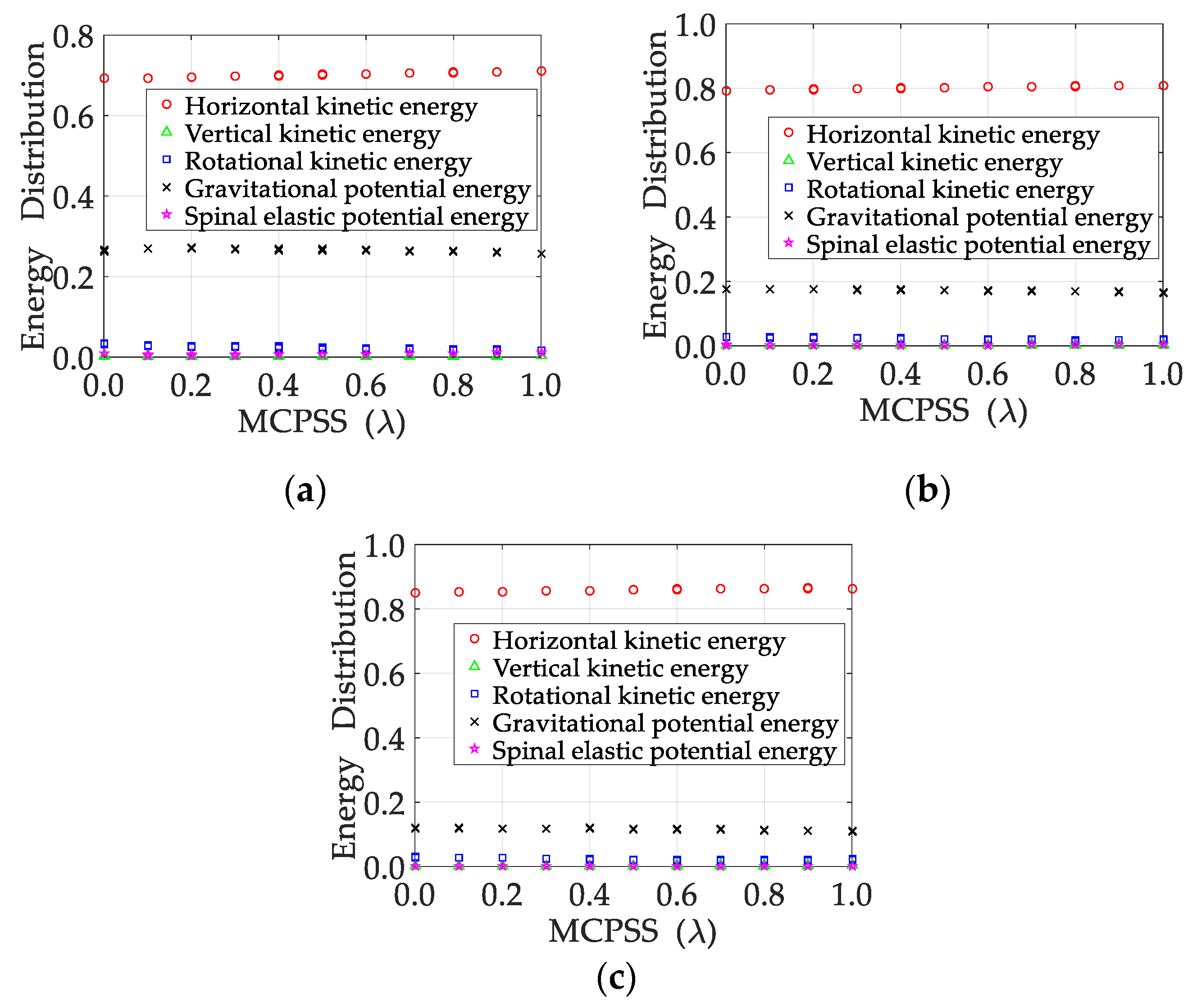
In this study, we observe that the horizontal speed of quadruped bounding is also maximum exactly at the Poincare section in a complete period. The distribution change of total mechanical energy can be seen as the internal cause of the changes of average maximum speed and other observable motion states. In this section, the effect of MCPSS on dynamic performances is to be explored from an energy perspective. The relation between MCPSS with the distribution of the total mechanical energy at the Poincare section is presented in Figure 8. The total mechanical energy consists of horizontal kinetic energy, vertical kinetic energy, rotational kinetic energy, spinal elastic potential energy, legged elastic potential energy, and the gravitational potential energy. The legged elastic potential energy is preset zero because the lengths of legs are all nominal at the Poincare section, so it is not presented in this figure.
It can be seen that, wherever MCPSS is, the horizontal kinetic energy and gravitational potential energy account for almost the main of the total mechanical energy; moreover, although the gravitational potential energy and rotational kinetic energy present observably monotonic decrease as the MCPSS moves from the spinal joint towards hip joint, but the changes are both very small. Therefore, it indicates that the varied MCPSS shows a light influence on the energy distribution of the total mechanical energy at the Poincare section.

4.5. Mass-Center Vertical Fluctuation

The mass-center vertical fluctuation is defined as the difference between the maximum with the minimum mass-center height of quadruped robot in the whole period of quadruped bounding. The smaller mass-center vertical fluctuation leads to more stable vertical motion, which represents a better resistance to vertical jitter.
The relation between MCPSS with mass-center vertical fluctuation is shown in Figure 9. It can be seen that the effect of MCPSS on mass-center vertical fluctuation is obvious at high speed, but implicit at low and medium speeds on the whole. Moreover, the mass-center vertical fluctuation presents the single valley variation as MCPSS moves from spinal joint to hip joint. The valley value of mass-center vertical fluctuation corresponds to MCPSS being near the geometric center of spinal segment at all speeds. In more detail, MCPSS with respect to the smallest mass-center vertical fluctuation corresponds to λ = 0.4 at low speed, and λ = 0.6 at medium and high speeds. Significantly, when the quadruped bounding is very fast horizontally, MCPSS being at the hip joint will cause considerable mass-center vertical fluctuations at all speeds. On the whole, MCPSS near the geometric center of spinal joint is an attractive choice with respect to mass-center vertical fluctuation, which can maintain a better resistance to the vertical jitter.

4.6. Maximum Foot-End Force

The maximum foot-end force is an important performance of quadruped bounding, which indirectly relates to the torque cost of joint drivers. The relation between MCPSS with maximum foot-end force is shown in Figure 10. It can be seen that the maximum foot-end force presents a single valley change, when MCPSS moves from the spinal joint towards the hip joint. In particular, MCPSS with respect to the valley value of maximum foot-end force are all near the geometric center of spinal segment at all speeds. Moreover, as the horizontal speed gets larger, MCPSS near hip joint leads to larger foot-end forces. Especially when the quadruped bounding is relative fast, the maximum foot-end force corresponding to MCPSS at the hip joint is almost 25% larger than that corresponding to MCPSS at the geometric center of spinal joint. On the whole, MCPSS near the geometric center of spinal joint is an ideal choice, which should decrease the high torque-demand for joint-drivers in reality.

4.7. Discussion

The results show that considering different horizontal speeds in target results is surely necessary. The change laws of some dynamic performances vary greatly at different horizontal speeds, even though the change of MCPSS remains same. For example, when MCPSS moves from the spinal joint to the geometric center of spinal segment gradually, the motion stability presents a monotonous decrease obviously at the low speed, but maintains a minor increase nearly at the medium and high speeds. For another example, when MCPSS moves from the geometric center of spinal segment to the hip joint gradually, the decrease of the spinal oscillation is more obviously at the high speed than at the low speed. In a word, the effect of the MCPSS on dynamic performances of quadruped bounding is significantly influenced by the horizontal speeds.
More importantly, the results at different horizontal speeds together make the optimal or suboptimal MCPSS more prominent with respect to the dynamic performances. That is, a certain MCPSS benefits a set of dynamic performances at any horizontal speed, and another MCPSS benefits another set of dynamic performances at any horizontal speed. With MCPSS near the hip joint, the stride period facilitates the leg-orientation control best, and the stride length, average horizontal speed, and horizontal kinetic energy benefit the fast horizontal bounding the most, and the minimum spinal oscillation also gives the largest margin of spinal pitch angle. They are satisfied at any horizontal speeds. The smallest duty factor is also obtained at the medium and high horizontal speeds when MCPSS is at the hip joint, which also support the fast horizontal bounding. All these show that MCPSS near the hip joint is best for the fast horizontal movement and leg-orientation control of the quadruped bounding. However, when MCPSS is near the geometric center of spinal segment, the smallest maximum foot-end force and the smallest mass-center vertical fluctuation are both obtained at any horizontal speeds, which can significantly enhance the resistance to the vertical jitter and reduce the high torque-demand of joint-drivers. The above results make the hip joint and the geometric center of spinal segment as two best positions for the corresponding dynamic performances.
Furtherly, for most real quadruped robots similar to the simplified quadruped model in this paper, the best MCPSS should be between the spinal joint and the geometric center of spinal segment, because most dynamic performances usually need to be met with equal importance. More simulations and experiments are needed to determine the best MCPSS for real quadruped robots.

5. Conclusions

In this paper, the effect of MCPSS on dynamic performances of quadruped bounding with a flexible-articulated spine is studied. A sagittal simplified model of the quadruped bounding is introduced to capture its dynamics characteristics, and MCPSS is set as an independent parameter. All the system parameters are normalized in a dimensionless form to make the target results available to this type of quadruped robots with different sizes. A large number of periodically quadruped bounding are generated to calculate the relations between dynamic performances with MCPSS at the low, medium, and high horizontal speeds, respectively.
The results show that the effect of MCPSS on dynamic performances of quadruped bounding is obviously influenced by the horizontal speeds. More importantly, the results indicate that MCPSS corresponding to the optimal or suboptimal dynamic performances mainly gather at two positions: the hip joint and the geometric center of spinal segment. MCPSS near the hip joint is best for the fast horizontal movement and leg-orientation control of the quadruped bounding, but MCPSS near the geometric center of spinal segment can significantly enhance the resistance to the vertical jitter and reduce the high torque-demand of joint-drivers. In addition, for a real quadruped robot, the optimal MCPSS should be between the hip joint and the geometric center of spinal segment.
This study can give helpful suggestions to the layout design of devices arranged on the flexible spine of this type of quadruped robot. Further research can consider more general quadruped robots with an asymmetrically segmented spine and two independent MCPSS. The comparisons of the effect mechanism of MCPSS on dynamic performances between the bounding and galloping gaits are also worth investigating.

Author Contributions

Conceptualization, S.Z. and Y.T.; investigation, S.Z. and Y.T.; methodology, S.Z. and Z.L.; software, P.W.; supervision, H.Y.; writing—original draft preparation, S.Z. and Y.T.; writing—review and editing, S.Z., T.L. and J.L. All authors have read and agreed to the published version of the manuscript.

Funding

This research was funded by Beijing Advanced Innovation Center for Intelligent Robots and Systems, Beijing, China, grant number 2019IRS18; This research was also funded by National Natural Science Foundation, China, grant number 91848102.

Conflicts of Interest

The authors declare no conflict of interest.

References

  1. English, A.W. The functions of the lumbar spine during stepping in the cat. J. Morphol. 1980, 165, 55–66. [Google Scholar] [CrossRef] [PubMed]
  2. Alexander, R.; Dimery, N.J.; Ker, R. Elastic structures in the back and their role in galloping in some mammals. J. Zool. 1985, 207, 467–482. [Google Scholar] [CrossRef]
  3. Lesser, K.F. Locomotion Experiments on a Planar Quadruped Robot with Articulated Spine. Master’s Thesis, MIT, Cambridge, MA, USA, 1996. [Google Scholar]
  4. Zhao, Q.; Ellenberger, B.; Sumioka, H.; Sandy, T.; Pfeifer, R. The effect of spine actuation and stiffness on a pneumatically-driven quadruped robot for cheetah-like locomotion. In Proceedings of the IEEE International Conference on Robotics and Biomimetics (ROBIO), Shenzhen, China, 12–14 December 2013. [Google Scholar]
  5. Seok, S.; Wang, A.; Chuah, M.Y.; Hyun, D.J.; Lee, J.; Otten, D.M.; Lang, J.H.; Kim, S. Design principles for energy-efficient legged locomotion and implementation on the MIT cheetah robot. IEEE-ASME Trans. Mechatron. 2015, 20, 1117–1129. [Google Scholar] [CrossRef] [Green Version]
  6. Hyun, D.J.; Lee, J.; Park, S.; Kim, S. Implementation of trot-to-gallop transition and subsequent gallop on the MIT Cheetah I. Int. J. Robot. Res. 2016, 35, 1627–1650. [Google Scholar] [CrossRef]
  7. Khoramshahi, M.; Sprowitz, A.; Tuleut, A.; Ahmadabadi, M.N.; Ijspeert, A.J. Benefits of an active spine supported bounding locomotion with a small compliant quadruped robot. In Proceedings of the IEEE International Conference on Robotics and Automation (ICRA), Karlsruhe, Germany, 6–10 May 2013. [Google Scholar]
  8. Eckert, P.; Sprowitz, A.; Witte, H.; Ijspeert, A.J. Comparing the effect of different spine and leg designs for a small bounding quadruped robot. In Proceedings of the IEEE International Conference on Robotics and Automation (ICRA), Seattle, Washington, 26–30 May 2015. [Google Scholar]
  9. Wei, X.H.; Wang, C.L.; Long, Y.J.; Wang, S.G. The effect of spine on the bounding dynamic performance of legged system. Adv. Robot. 2015, 29, 973–987. [Google Scholar] [CrossRef]
  10. Callen, F.; Stacey, S.; Amir, P. The Effect of Spine Morphology on Rapid Acceleration in Quadruped Robots. In Proceedings of the IEEE/RSJ International Conference on Intelligent Robots and Systems (IROS), Vancouver, BC, Canada, 24–28 September 2017. [Google Scholar]
  11. Yesilevskiy, Y.; Yang, W.; Remy, C.D. Spine morphology and energetics: How principles from nature apply to robotics. Bioinspir. Biomim. 2018, 13, 036002. [Google Scholar] [CrossRef]
  12. Cao, Q.; Poulakakis, I. Quadrupedal bounding with a segmented flexible torso: Passive stability and feedback control. Bioinspir. Biomim. 2013, 8, 046007. [Google Scholar] [CrossRef] [PubMed] [Green Version]
  13. Cao, Q.; Poulakakis, I. On the energetics of quadrupedal running: Predicting the metabolic cost of transport via a flexible-torso model. Bioinspir. Biomim. 2015, 10, 056008. [Google Scholar] [CrossRef] [Green Version]
  14. Nie, H.; Sun, R.L.; Xiong, C.H. The effect of asymmetrical body-mass distribution on the stability and dynamics of quadruped bounding with articulated spine. In Proceedings of the 8th International Conference on Intelligent Robotics and Applications (ICIRA), Portsmouth, UK, 24–27 August 2015. [Google Scholar]
  15. Phan, L.T.; Lee, Y.H.; Kim, D.Y.; Lee, H.; Choi, H.R. Hybrid quadruped bounding with a passive compliant spine and asymmetric segmented body. In Proceedings of the 2016 IEEE/RSJ International Conference on Intelligent Robots and Systems (IROS), Daejeon, South Korea, 9–14 October 2016. [Google Scholar]
  16. Pouya, S.; Khodabakhsh, M.; Spröwitz, A.; Ijspeert, A. Spinal joint compliance and actuation in a simulated bounding quadruped robot. Auton. Robot. 2017, 41, 437–452. [Google Scholar] [CrossRef]
  17. Zou, H.; Schmiedeler, J.P. The effect of asymmetrical body-mass distribution on the stability and dynamics of quadruped bounding. IEEE Trans. Robot. 2006, 22, 711–723. [Google Scholar]
  18. Remy, C.D.; Buffinton, K.; Siegwart, R. A MATLAB framework for efficient gait creation. In Proceedings of the IEEE/RSJ International Conference on Intelligent Robots and Systems (IROS), San Francisco, CA, USA, 25–30 September 2011. [Google Scholar]
  19. Li, Z.; Tan, Y.G.; Wu, P.; Zeng, S. The compliant effect of controlled spine on interaction with the ground in quadruped trotting. Proc. Inst. Mech. Eng. Part I J. Syst. Control Eng. 2020, 234, 27–45. [Google Scholar] [CrossRef]
  20. Guckenheimer, J.; Holmes, P. Nonlinear Oscillations, Dynamical Systems, and Bifurcations of Vector Fields; Springer: New York, NY, USA, 1983. [Google Scholar]
  21. Clerc, M.; Kennedy, J. The particle swarm-explosion, stability, and convergence in a multidimensional complex space. IEEE Trans. Evol. Comput. 2002, 6, 58–73. [Google Scholar] [CrossRef] [Green Version]
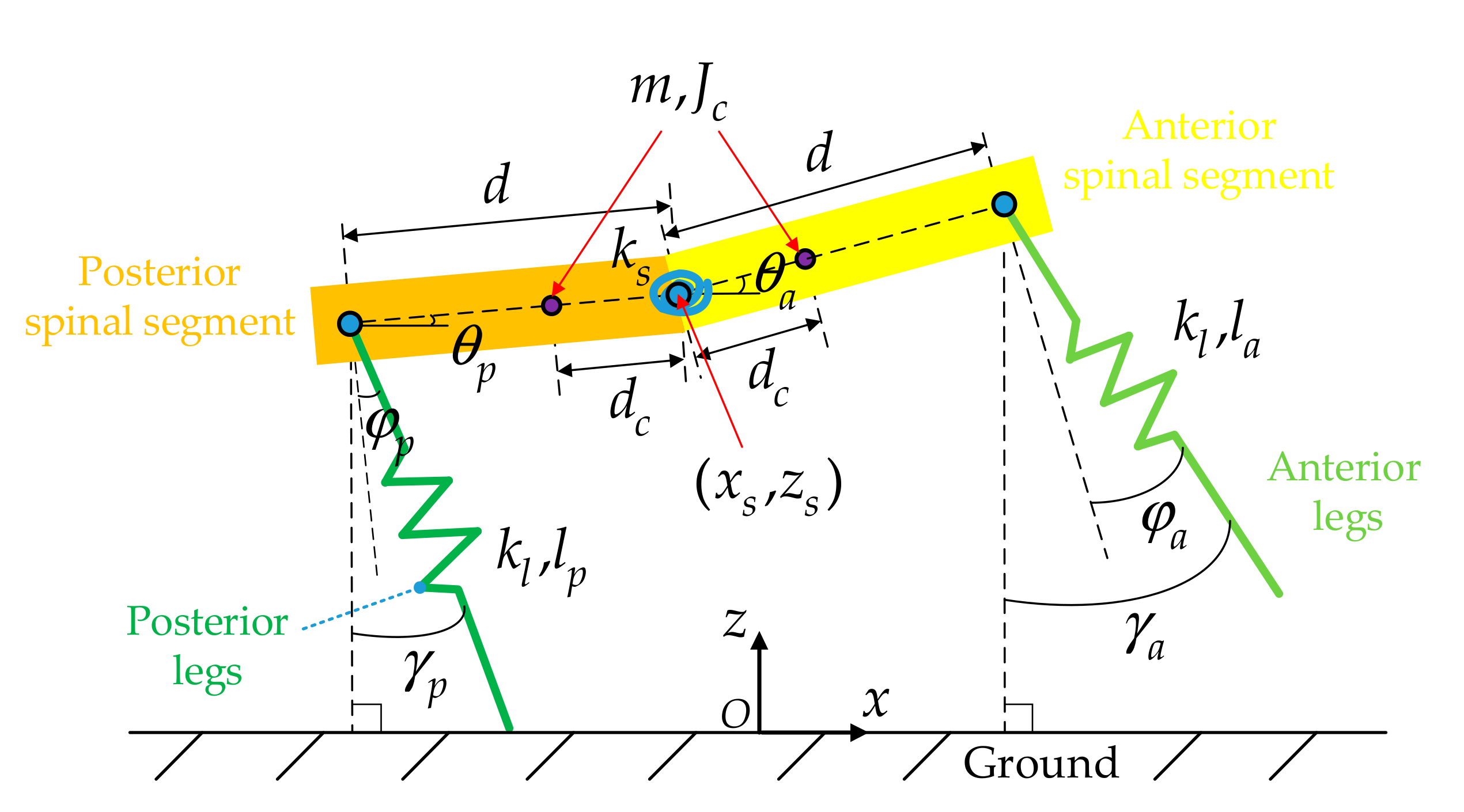
Figure 1. A sagittal simplified model of quadruped bounding with a flexible-articulated spine.
Applsci 10 01491 g001
Figure 2. Phase transitions of every leg. The anterior and posterior legs are distinguished by subscript ‘ a ’, ’ p ’, respectively. The motion of the whole period of every leg is divided into two stages (stance stage and swing stage) or three phases (flight phase, stance phase, and climbout phase). The leg-phase (blue blocks) which can be identified by ‘1’, ‘2’, and ’3’ transits with the event-trigger (purple words) which can be identified by ‘01’, ’02’, and ’03’.
Applsci 10 01491 g002
Figure 3. Relations of the stiffness of the spinal joint ( k s * ), the stiffness of leg ( k l * ), and the total mechanical energy ( E * ) with different horizontal speeds at the Poincare section ( x ˙ s i n * ): (a) k s * with x ˙ s i n * ; (b) k l * with x ˙ s i n * ; (c) E * with x ˙ s i n * .
Applsci 10 01491 g003
Figure 4. (a) Snapshots of quadruped bounding during a whole period. From (a) to (g): liftoff of anterior legs, touchdown of posterior legs, liftoff of posterior legs, flying of anterior legs, flying of posterior legs, touchdown of anterior legs, liftoff of anterior legs. (b) Evolution of the pitch angles of the anterior spinal segment (green dotted), the posterior spinal segment (blue dotted), and the spinal joint (red solid) of quadruped bounding in the whole period; letters correspond to the snapshots in (a). (c) Evolution of the foot-end forces of the anterior and posterior legs. (d) Evolution of the mass-center horizontal position. (e) Evolution of the mass-center horizontal speed. (f) Evolution of the mass-center vertical position. (g) Evolution of mass-center vertical speed. The vertical dotted line signifies the same events in (a).
Applsci 10 01491 g004aApplsci 10 01491 g004b
Figure 5. Relation between motion stability with different mass-center position of spinal segment (MCPSS) at the low (red circle), medium (green triangle), and high (blue quadrilateral) horizontal speeds, respectively.
Applsci 10 01491 g005
Figure 6. Relations between MCPSS with gait characteristics including the stride period (a), the stride length (b), the average horizontal speed (c), and the duty factor (d). The red circle, green triangle, and blue quadrilateral correspond to the low, medium, and high horizontal speeds, respectively.
Applsci 10 01491 g006
Figure 7. Relation between MCPSS with the spinal oscillation at the low (red circle), medium (green triangle), and high (blue quadrilateral) horizontal speeds, respectively.
Applsci 10 01491 g007
Figure 8. Relations between MCPSS with the energy distribution of the total mechanical energy of quadruped bounding at the Poincare section shown at the low (a), medium (b), and high (c) horizontal speeds, respectively.
Applsci 10 01491 g008
Figure 9. Relation between MCPSS with the mass-center vertical fluctuation at the low (red circle), medium (green triangle), and high (blue quadrilateral) horizontal speeds, respectively.
Applsci 10 01491 g009
Figure 10. Relation between MCPSS with the maximum foot-end force at the low (red circle), medium (green triangle), and high (blue quadrilateral) horizontal speeds, respectively.
Applsci 10 01491 g010
Table 1. The given values of m * , d * , J c * , and l 0 * .
ParametersValues
m * 0.5
d * 0.5
J c * 0.0878
l 0 * 0.6522
Table 2. The chosen combination of k s * , k l * , and E * at the low ( x ˙ s i n * = 1.8 ), medium ( x ˙ s i n * = 2.4 ), and high ( x ˙ s i n * = 3.0 ) horizontal speeds, respectively.
ParameterValue
x ˙ s i n * 1.82.43.0
k s * 1.411.020.62
k l * 22.0931.9733.43
E * 2.343.635.30