Effect of Bentonite Addition on the Properties of Fly Ash as a Material for Landfill Sealing Layers


Abstract
1. Introduction
2. Materials and Methods
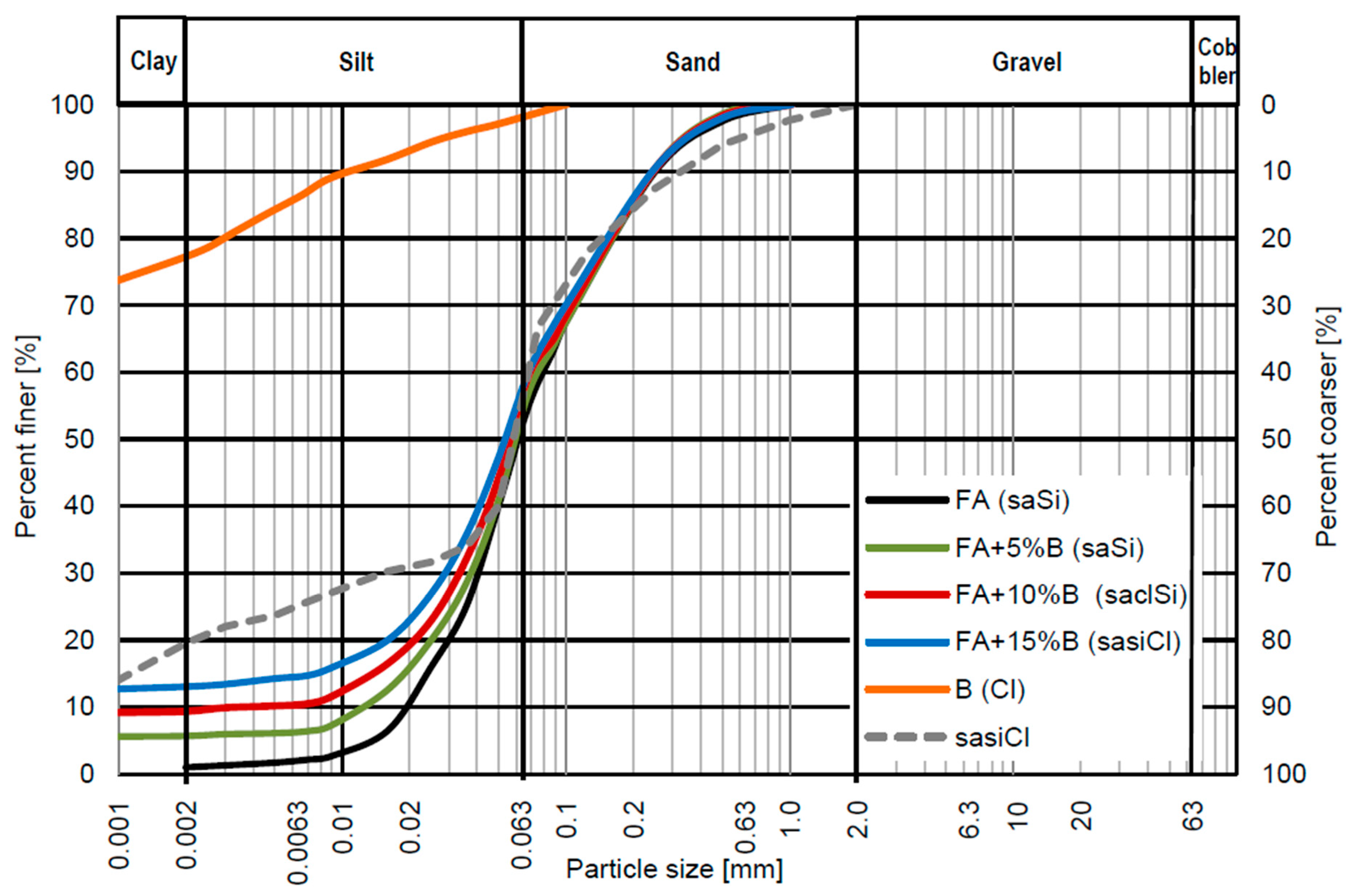
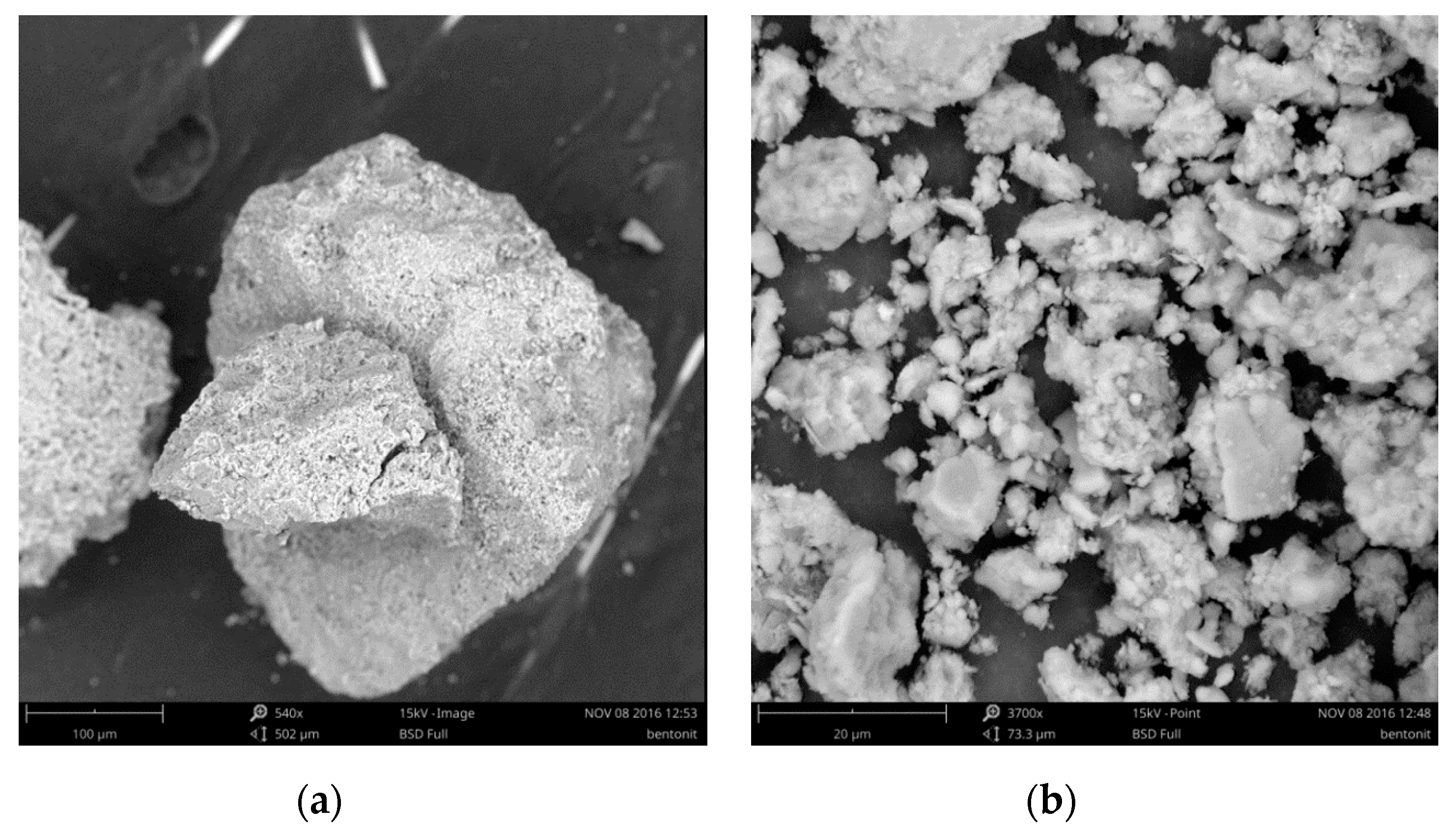
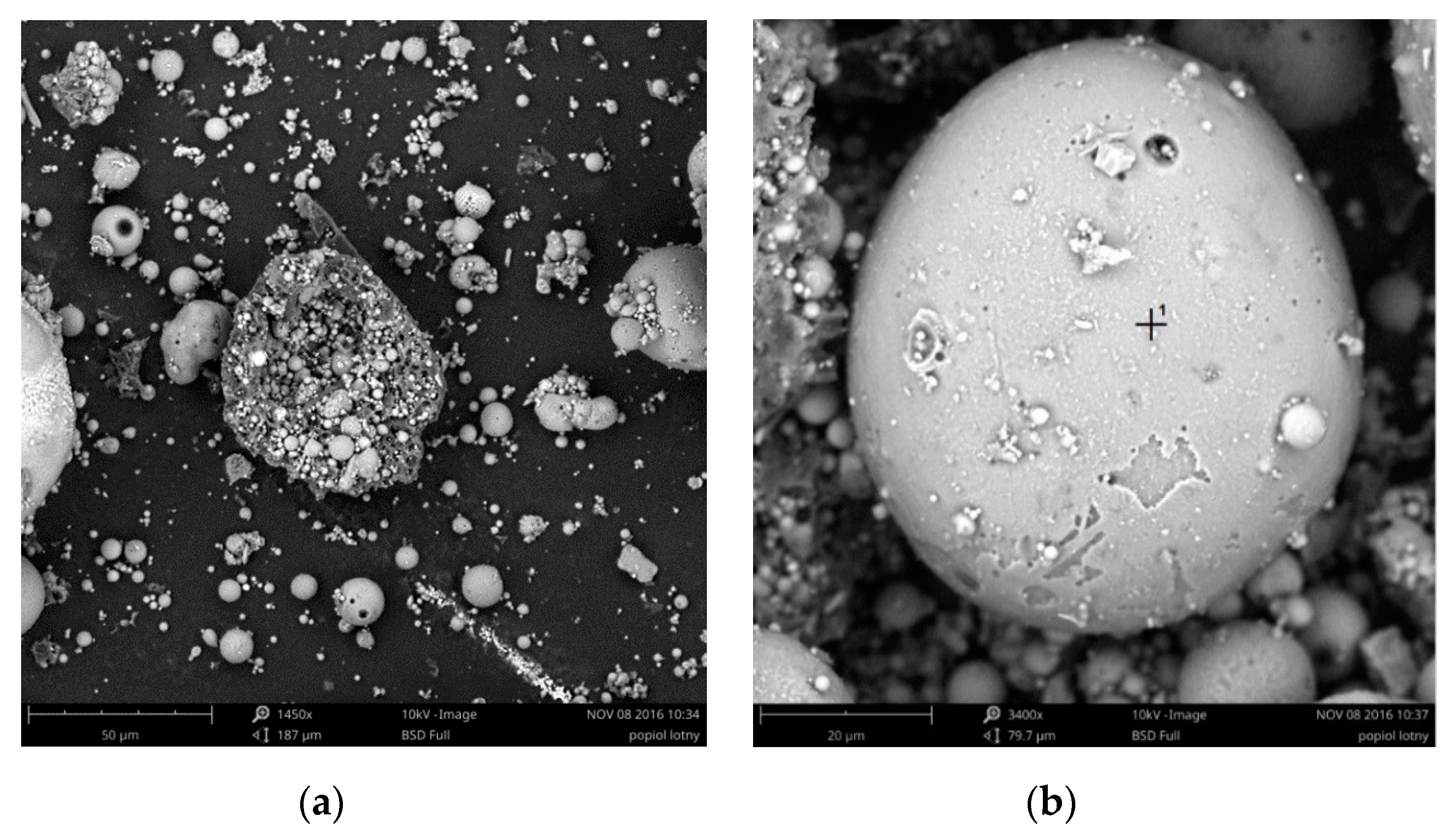
2.1. Materials
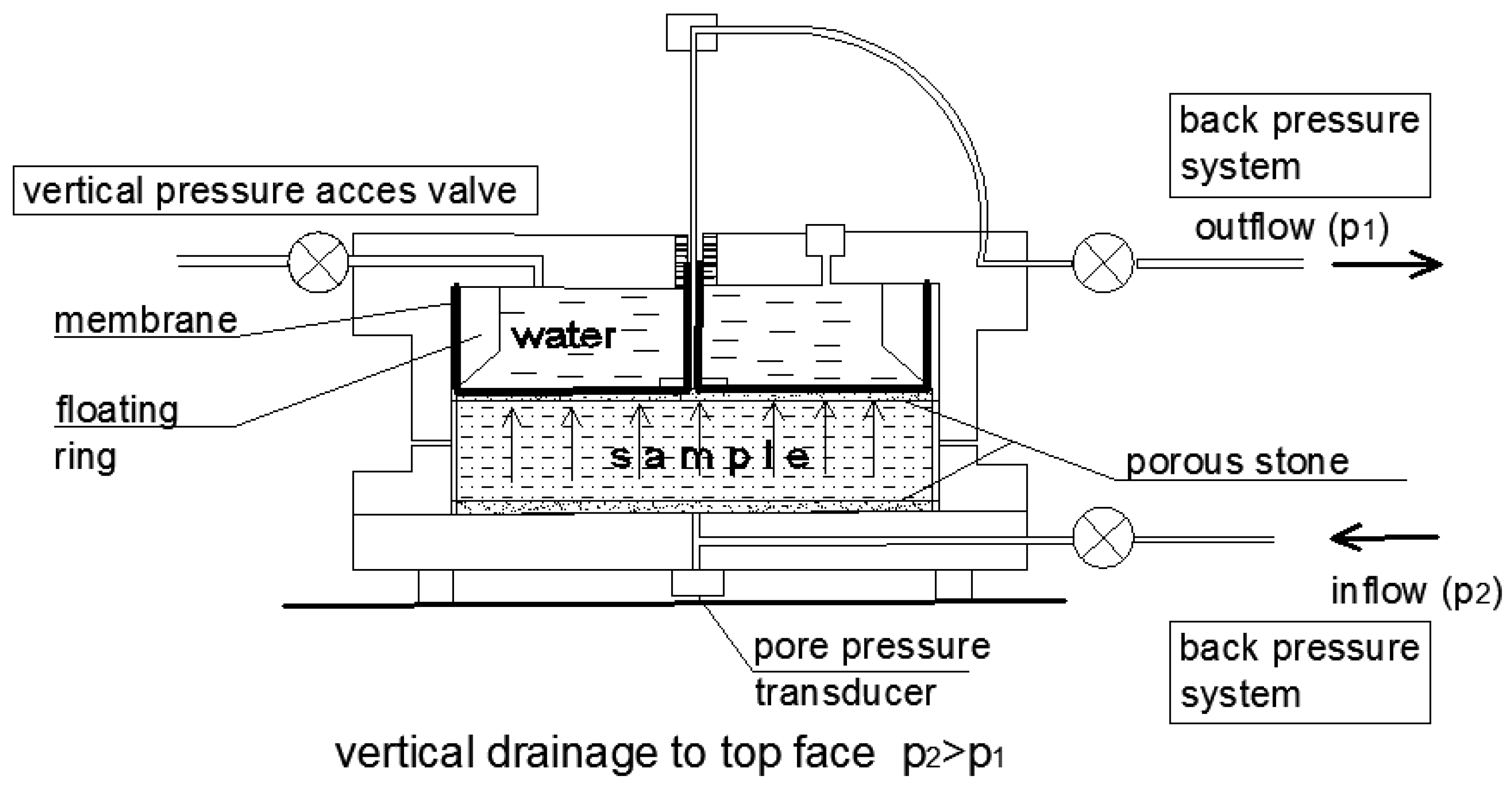
2.2. Methods
3. Results and Discussion
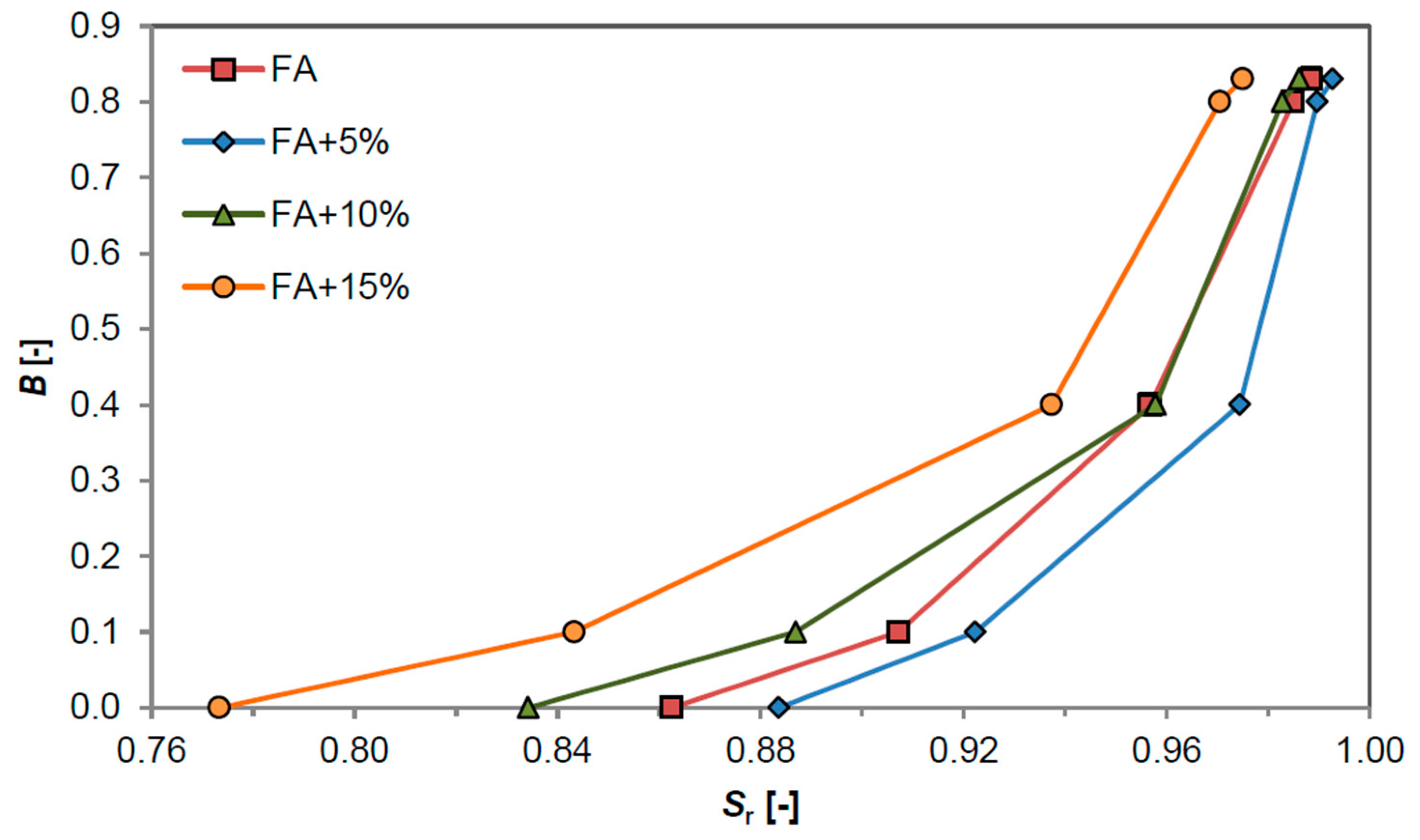
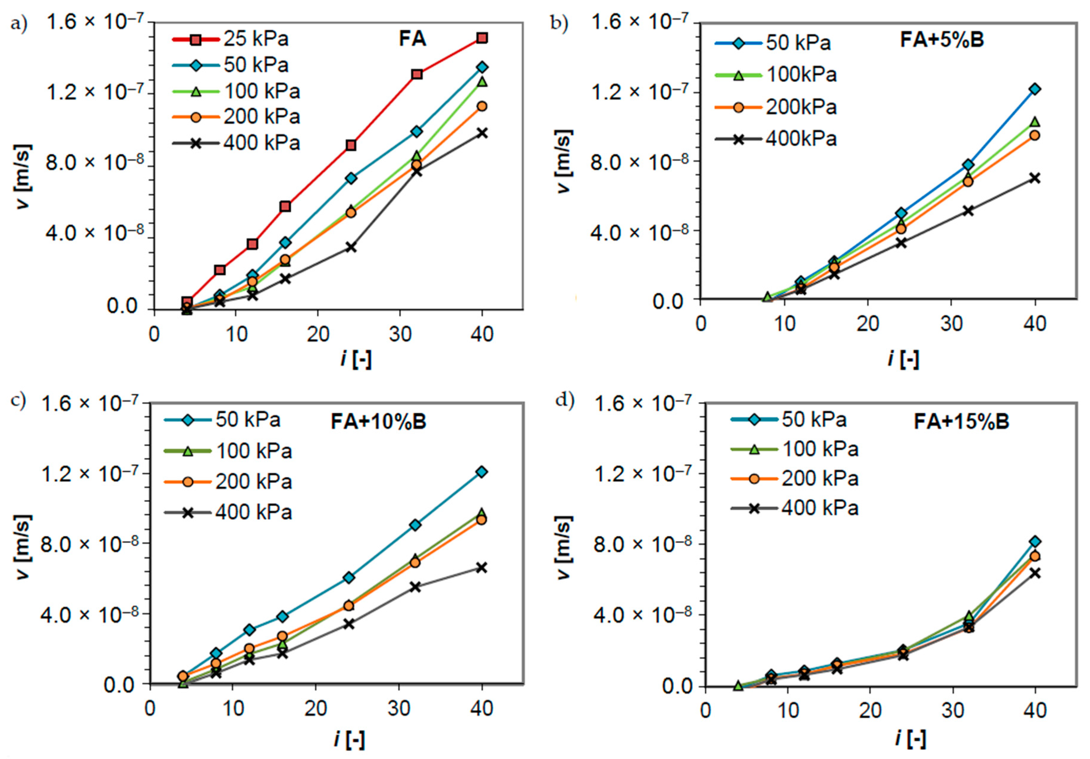
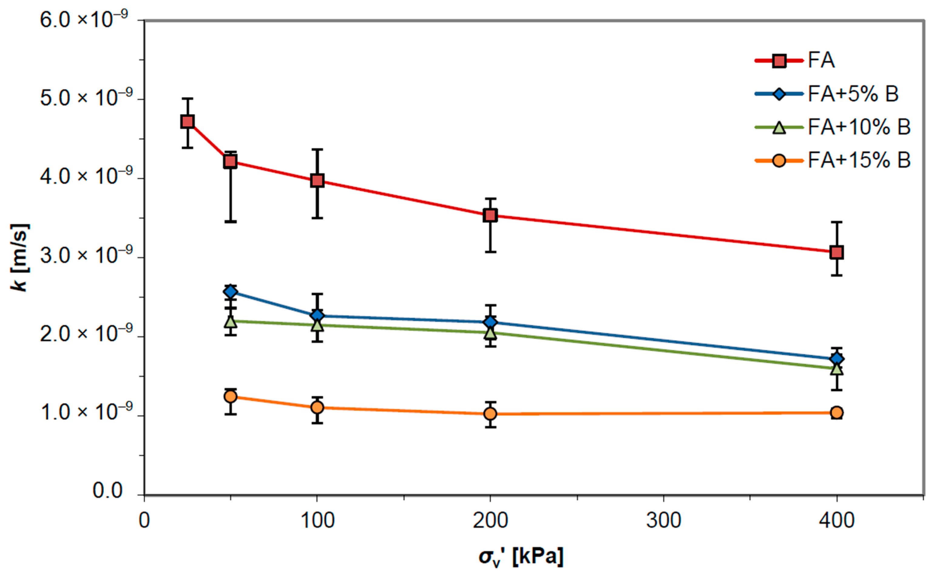
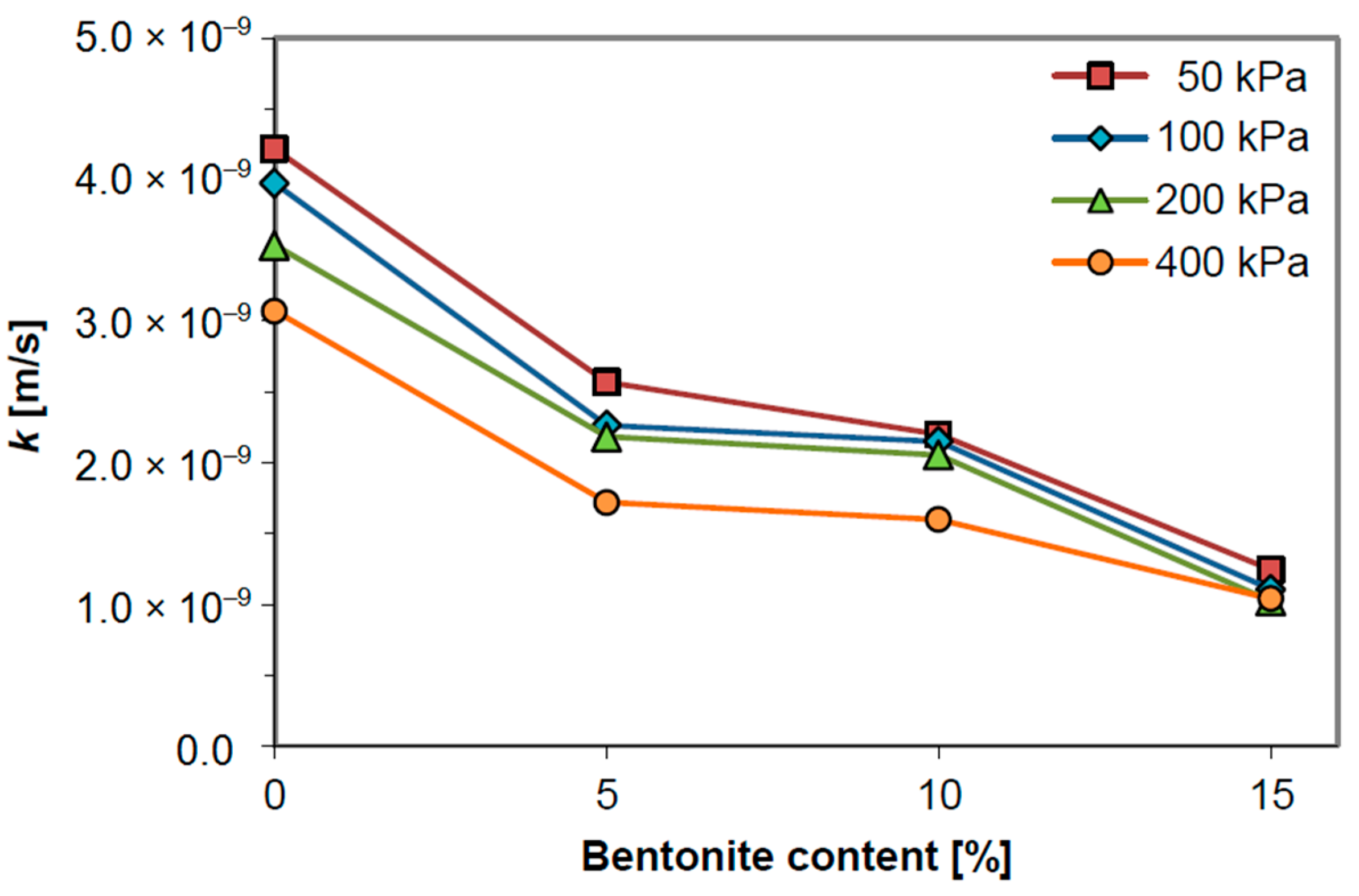
3.1. Hydraulic Conductivity
3.2. Cohesive Soil
4. Conclusions
- Bentonite addition to fly ash causes a decrease in optimal moisture content (OMC) and an increase in maximum dry density (MDD) of the mixes. The specific density of fly ash and fly ash mixes is lower than for natural soils.
- The specific surface area increased with the amount of bentonite addition to the fly ash.
- With the addition of bentonite to fly ash, hydraulic conductivity of the mixture is decreased compared to that of fly ash alone. Samples with bentonite addition in the amount of 5%, 10% and 15% by dry weight tested at i = 32 and σ’ = 400 kPa resulted in the decrease in hydraulic conductivity value: about twice, twice and three times in relation to the fly ash, respectively. The hydraulic conductivity values of fly ash may be reduced to the values ≤1.0 × 10⁻⁹ m/s with 15% of bentonite addition and it meets the criteria of a compacted liner and cover materials in terms of hydraulic conductivity.
- Fly ash and fly ash-bentonite mixtures with a lower amount of bentonite meets the requirement for the sealing layers of landfill of inert wastes, where the hydraulic conductivity k should have a value equal or lower than 1.0 × 10⁻⁷ m/s.
- Hydraulic conductivity of fly ash and fly ash-bentonite mixtures should be tested under conditions of a fully saturated sample in order to produce reliable results.
- The lowest values of hydraulic conductivity were obtained for sandy silty clay, which was caused by its higher specific surface area in relation to fly ash-bentonite mixtures.
Funding
Conflicts of Interest
References
- Daniel, D.E. Geotechnical Practice for Waste Disposal; David, E.D., Ed.; Chapman & Hall: London, UK, 1997. [Google Scholar]
- Daniel, D.E.; Koerner, R.M. Waste Containment Facilities. In Guidance for Construction, Quality Assurance and Quality Control of Liner and Cover Systems; ASCE Press: New York, NY, USA, 1995. [Google Scholar]
- Shackelford, C.D.; Benson, C.H.; Katsumi, T.; Edil, T.B.; Lin, L. Evaluating the hydraulic conductivity of GCLs permeated with non-standard liquids. Geotext. Geomembr. 2000, 18, 137–161. [Google Scholar] [CrossRef]
- Bonaparte, R.; Daniel, D.; Koerner, R. Assessment and Recommendations for Improving the Performance of Waste Containment Systems; CR-821448-01-0; Environmental Protection Agency: Washington, DC, USA, 2002. [Google Scholar]
- Rowe, R.K.; Quigley, R.M.; Brachman, R.W.I.; Booker, J.R. Barrier Systems for Waste Disposal Facilities, 2nd ed.; Taylor & Francis: London, UK, 2004. [Google Scholar]
- European Union (EU). Council Directive 99/31/EC of 26 April 1999 on the Landfill of Waste; Council of the European Union: Brussels, Belgium, 1999. [Google Scholar]
- Wysokiński, L. (Ed.) Principles of Assessing the Suitability of Cohesive Soils of Poland for the Construction of Mineral Insulating Barriers; ITB, Ministry of Environment: Warsaw, Poland, 2007. (In Polish) [Google Scholar]
- Leonards, G.A.; Bailey, B. Pulverized coal ash as structural fill. J. Geotech. Eng. 1982, 108, 517–531. [Google Scholar]
- Kim, B.; Prezzi, M.; Salgado, R. Geotechnical properties of fly and bottom ash mixtures for use in highway embankments. J. Geotech. Geoenviron. Eng. 2005, 131, 914–924. [Google Scholar] [CrossRef]
- Behera, B.; Mishra, M.K. California bearing ratio and brazilian tensile strength of mine overburden-fly ash-lime mixtures for mine haul road construction. Geotech. Geol. Eng. 2012, 30, 449–459. [Google Scholar] [CrossRef]
- Pandian, N.S. Fly ash characterization with reference to geotechnical applications. J. Ind. Inst. Sci. 2004, 84, 189–216. [Google Scholar]
- Rai, A.K.; Paul, B.; Singh, G. A study on backfill properties and use of fly ash for highway embankments. J. Adv. Lab. Res. Biol. 2010, 1, 110–114. [Google Scholar]
- Sear, L.K.A. Properties and use of coal fly ash. In A Valuable Industrial By-Product; Thomas Telford Ltd.: London, UK, 2001. [Google Scholar]
- Zabielska-Adamska, K. Fly Ash as a Barrier Material; Bialystok University of Technology Publishing House: Białystok, Poland, 2006. (In Polish) [Google Scholar]
- LaGrega, M.D.; Buckingham, P.L.; Evans, J.C. Hazards Waste Management; McGraw-Hill Inc.: New York, NY, USA, 1994. [Google Scholar]
- Yao, Z.; Ji, X.; Sarker, P.; Tang, J.; Ge, L.; Xia, M.; Xi, Y. A comprehensive review on the applications of coal fly ash. Earth-Sci. Rev. 2015, 141, 105–121. [Google Scholar] [CrossRef]
- Edil, T.B.; Sandstrom, L.K.; Berthouex, P.M. Interaction of inorganic leachate with compacted pozzolanic fly ash. J. Geotech. Geoenviron. Eng. 1992, 118, 1410–1430. [Google Scholar] [CrossRef]
- Prashanth, J.P.; Sivapullaiah, P.V.; Sridharan, A. Pozzolanic fly ash as a hydraulic barrier in land fills. Eng. Geol. 2001, 60, 245–252. [Google Scholar] [CrossRef]
- El Moudni El Alami, S.; Moussaoui, R.; Monkade, M.; Lahlou, K.; Hasheminejad, N.; Margaritis, A.; Van den bergh, W.; Vuye, C. Lime Treatment of Coal Bottom Ash for Use in Road Pavements: Application to El Jadida Zone in Morocco. Materials 2019, 12, 2674. [Google Scholar] [CrossRef]
- Samanta, M. Investigation on geomechanical behaviour and microstructure of cement-stabilized fly ash. Int. J. Geotech. Eng. 2018, 12, 449–461. [Google Scholar] [CrossRef]
- Mollamahmutoğlu, M.; Yilmaz, Y. Potential use of fly ash and bentonite mixture as liner or cover at waste disposal areas. Environ. Geol. 2001, 40, 1316–1324. [Google Scholar] [CrossRef]
- Palmer, B.; Edil, T.B.; Benson, C. Liners for waste containment constructed with class F and C fly ashes. J. Hazard. Mater. 2000, 76, 193–216. [Google Scholar] [CrossRef]
- Sivapullaiah, P.V.; Lakshmikantha, H. Properties of Fly Ash as Hydraulic Barrier. Soil Sedim. Contamin. 2004, 13, 391–406. [Google Scholar] [CrossRef]
- Srikanth, V.; Mishra, A.K. A laboratory study on the geotechnical characteristics of sand–bentonite mixtures and the role of particle size of sand. Int. J. Geosynth. Ground Eng. 2016, 3, 1–10. [Google Scholar] [CrossRef]
- Meier, A.J.; Shackelford, C.D. Membrane behavior of compacted sand–bentonite mixture. Can. Geotech. J. 2017, 9, 1284–1299. [Google Scholar] [CrossRef]
- Shackelford, C.; Glade, M. Constant-flow and constant gradient permeability on sand-bentonite-fly ash mixtures. In Hydraulic Conductivity and Waste Contaminant Transport in Soil; Daniel, D., Trautwein, S., Eds.; ASTM: Philadelphia, PA, USA, 1985; pp. 521–545. [Google Scholar]
- Elmashad, M.M.A. Improving the geotechnical behavior of sand through cohesive admixtures. Water Sci. 2018, 32, 67–78. [Google Scholar] [CrossRef]
- Nguyen, L.C.; Chu, H.L.; Ho, L.S. Soil treatment by bentonite and fly ash for liners of waste landfill: A case study in Vietnam. Int. J. GEOMATE 2019, 17, 315–322. [Google Scholar] [CrossRef]
- Sobti, J.; Singh, S.K. Hydraulic conductivity and compressibility characteristics of bentonite enriched soils as a barrier material for landfills. Innov. Infrastruct. Solut. 2017, 12, 1–13. [Google Scholar] [CrossRef]
- Zabielska-Adamska, K.; Wasil, M. Tensile strength of barrier material. In Proceedings of the 10th International Conference “Environmental Engineering”, Vilnius, Lithuania, 27–28 April 2017. [Google Scholar]
- ISO 14688-2:2017. Geotechnical Investigation and Testing—Identification and Classification of Soil—Part 2: Principles for a Classification; ISO: Geneva, Switzerland, 2017. [Google Scholar]
- Rowe, R.K.; Quigley, R.M.; Booker, J.R. Clayey Barrier Systems for Waste Disposal Facilities; CRC Press, Taylor and Francis: Boca Raton, FL, USA, 1997; ISBN 9780419226000. [Google Scholar]
- ASTM C618. Standard Specification for Coal Fly Ash and Raw or Calcined Natural Pozzolan for Use in Concrete; American Society for Testing and Materials: West Conshohocken, PA, USA, 2015. [Google Scholar]
- Cokca, E.; Yilmaz, Z. Use of rubber and bentonite added fly ash as a liner material. Waste Manag. 2004, 24, 153–164. [Google Scholar] [CrossRef]
- PN EN 13286-2:2010 AC 2014. Unbound and Hydraulically Bound Mixtures—Part 2: Test Methods for Laboratory Reference Density and Water Content—Proctor Compaction; Polish Committee for Standardization: Warsaw, Poland, 2014. [Google Scholar]
- Zabielska-Adamska, K. Laboratory Compaction of Fly Ash and Fly Ash with Cement Additions. J. Hazard. Mater. 2008, 151, 481–489. [Google Scholar] [CrossRef] [PubMed]
- BS 1377-6:1990. Methods of Test for Soils for Civil Engineering Purposes. Part 6. Consolidation and Permeability Tests in Hydraulic Cells and with Pore Pressure Measurement; British Standard Institution: London, UK, 1990. [Google Scholar]
- Skempton, A.W. The pore-pressure coefficients A and B. Géotechnique 1954, 4, 143–147. [Google Scholar] [CrossRef]
- Lipiński, M.J.; Wdowska, M.K. Saturation criteria for heavy overconsolidated cohesive soils. Ann. Warsaw Univ. Life Sci. SGGW Land Reclam. 2010, 42, 295–302. [Google Scholar] [CrossRef]
- Shahu, J.; Yudhbir, T.; Kameswara Rao, N.S.V. Effective stress behavior of quasi-saturated compacted cohesive soils. J. Geotech. Geoenviron. Eng. 1999, 125, 322–329. [Google Scholar] [CrossRef]
- Cartwright, K.; Hensel, B.R. Hydrogeology. In Geotechnical Practice for Waste Disposal; Daniel, D.E., Ed.; Chapman & Hall: London, UK, 1997; pp. 66–93. [Google Scholar]
- Craig, R.F. Craig’s Soil Mechanics, 7th ed; Spoon Press: New York, NY, USA, 2004. [Google Scholar]
- Hansbo, S. Consolidation equation valid for both Darcian and non-Darcian flow. Géotechnique 2001, 51, 51–54. [Google Scholar] [CrossRef]
- Hansbo, S. Deviation from Darcy’s law observed in one dimensional consolidation. Géotechnique 2003, 53, 601–605. [Google Scholar] [CrossRef]
- Lambe, T. The Permeability of Compacted Fine-Grained Soils; Special Technical Publication No. 163; American Society of Testing and Materials (ASTM): Philadelphia, Pa, USA, 1964; pp. 56–67. [Google Scholar]
- Liu, C.N.; Gilbert, R.B.; Thiel, R.S.; Wright, S.G. What is an appropriate factor of safety for landfill cover slopes. In Proceedings of the Geosynthetics ‘97 Conference, Lang Beach, Industrial Fabrics Association International, Roseville, MN, USA, 11–13 March 1997; pp. 48–496. [Google Scholar]
- Bonaparte, R.; Yanful, E.K. Covers for waste. In Geotechnical and Geoenvironmental Engineering Handbook; Rowe, R.K., Ed.; Springer: Boston, MA, USA, 2001; pp. 825–877. ISBN 978-1-4615-1729-0. [Google Scholar]
- Nhan, C.T.; Graydon, J.W.; Kirk, D.W. Utilizing coal fly ash as a landfill barrier material. Waste Manag. 1996, 16, 587–595. [Google Scholar] [CrossRef]
- European Technical Committee No. 8 (ETC 8). Geotechnics of Landfill Design and Remedial Works—Technical Recommendation GLR; Ernst and Sohn: Berlin, Germany, 1993. [Google Scholar]
- Zabielska-Adamska, K. One-dimensional compression and swelling of compacted fly ash. Geotech. Res. 2018, 5, 96–105. [Google Scholar] [CrossRef]
- Santamarina, J.C.; Klein, K.A.; Wang, Y.H.; Prencke, E. Specific surface: Determination and relevance. Can. Geotech. J. 2002, 39, 233–241. [Google Scholar] [CrossRef]
- Farrar, D.; Coleman, J. The correlation of surface area with other properties of nineteen British clay soils. J. Soil Sci. 1967, 18, 118–124. [Google Scholar] [CrossRef]
- Mbonimpa, M.; Aubertin, M.; Chapuis, R.P.; Busiére, B. Practical pedotransfer functions for estimating the saturated hydraulic conductivity. Geotech. Geol. Eng. 2002, 20, 235–259. [Google Scholar] [CrossRef]
- Chapuis, R.P.; Aubertin, M. On the use of the Kozeny-Carman equation to predict the hydraulic conductivity of soils. Can. Geotech. J. 2003, 40, 616–628. [Google Scholar] [CrossRef]
- Chapuis, R.P.; Aubertin, M. Predicting the Coefficient of Permeability od Soils using the Kozeny-Carman Equation; Report EPM–RT–2003-03; Département des génies civil, géologique et des mines, École Polytechnique de Montréal: Montreal, QC, Canada, 2003. [Google Scholar]
- Steiakakis, E.; Gamvroudis, C.; Alevizos, G. Kozeny-Carman equation and hydraulic conductivity of compacted clayey soils. Geomatrials 2012, 2, 37–41. [Google Scholar] [CrossRef]


| Element | FA | B | Chemical Compound | FA | B |
|---|---|---|---|---|---|
| Si | 22.4% | 31.1% | SiO2 | 43.3% | 71.6% |
| Al | 15.8% | 7.7% | Al2O3 | 31.8% | 18.4% |
| Ca | 0.8% | 1.9% | C | 15.8% | – |
| An | – | 1.5% | K2O | 3.4% | – |
| Mg | 1.0% | 1.0% | Fe2O3 | 1.8% | – |
| K | 2.5% | – | MgO | 2.2% | 2.6% |
| Fe | 1.9% | – | CaO | 1.1% | 3.1% |
| C | 3.5% | – | TiO2 | 0.6% | – |
| Ti | 0.6% | – | Na2O | – | 4.3% |
| Tested Material | Specific Density ρs (Mg/m3) | Compaction Parameters | Specific Surface Area Ss (m2/g) | |
|---|---|---|---|---|
| Optimum Moisture Content (OMC) (%) | Maximum Dry Density (MDD) (Mg/m3) | |||
| FA | 2.18 | 40.0 | 1.073 | 21.01 |
| FA+5%B | 2.18 | 39.0 | 1.100 | 42.24 |
| FA+10%B | 2.22 | 36.3 | 1.118 | 57.90 |
| FA+15%B | 2.24 | 33.0 | 1.134 | 67.73 |
| sasiCl | 2.68 | 14.0 | 1.950 | 102.58 |
© 2020 by the author. Licensee MDPI, Basel, Switzerland. This article is an open access article distributed under the terms and conditions of the Creative Commons Attribution (CC BY) license (http://creativecommons.org/licenses/by/4.0/).
Share and Cite
Wasil, M. Effect of Bentonite Addition on the Properties of Fly Ash as a Material for Landfill Sealing Layers. Appl. Sci. 2020, 10, 1488. https://doi.org/10.3390/app10041488
Wasil M. Effect of Bentonite Addition on the Properties of Fly Ash as a Material for Landfill Sealing Layers. Applied Sciences. 2020; 10(4):1488. https://doi.org/10.3390/app10041488
Chicago/Turabian StyleWasil, Mariola. 2020. "Effect of Bentonite Addition on the Properties of Fly Ash as a Material for Landfill Sealing Layers" Applied Sciences 10, no. 4: 1488. https://doi.org/10.3390/app10041488
APA StyleWasil, M. (2020). Effect of Bentonite Addition on the Properties of Fly Ash as a Material for Landfill Sealing Layers. Applied Sciences, 10(4), 1488. https://doi.org/10.3390/app10041488