Article

Analysis of the Dynamic Characteristics of the Muzzle Flow Field and Investigation of the Influence of Projectile Nose Shape

Department of Arms and control, Army Academy of Armored Forces, Beijing 100072, China
*
Author to whom correspondence should be addressed.
Appl. Sci. 2020, 10(4), 1468; https://doi.org/10.3390/app10041468
Submission received: 15 January 2020 / Revised: 15 February 2020 / Accepted: 18 February 2020 / Published: 21 February 2020
(This article belongs to the Section Applied Physics General)

Abstract

:
In the present work, a numerical study of the dynamic processes occurring during projectile ejection from the open-end of a gun into ambient air was performed. The two-dimensional unsteady Navier–Stokes equations, assuming axisymmetric flow, were solved using an AUSM+ discrete scheme implemented with dynamic mesh boundary conditions. Five cases were carried out in the present study. First, two test cases were simulated to validate the numerical algorithms. The last three cases were used to investigate the blast flow field induced by the projectile nose shapes of flat-nosed, cone-nosed, and blunt-nosed projectiles. The study shows that some wave processes, such as shock–shock interactions, separated flow generation, and the Richtmyer–Meshkov Instability, are changed obviously with the change of projectile shape. The present study aims to deepen the understanding of the dynamic processes of unsteady muzzle flow during the projectile ejection.

1. Introduction

The dynamic characteristics of the muzzle flow field are closely associated with the firing process of the gun. For example, the effect of muzzle jet flow on the barrel influences the recoil of the barrel. The shock wave field of the muzzle may cause damage to neighbouring equipment and personnel. Therefore, numerous scholars have conducted research on this topic [1,2,3]. With the the development of high-performance computing and accurate numerical approaches, studying complex wave system using computational fluid dynamics (CFD) has become an important means to analyze the dynamic characteristics of muzzle flow fields. Different scholars have used various projectile model shapes for studying muzzle flow field. Jiang Z et al. [4,5] used a flat-nosed model to study the dynamic processes of the flow field such as shock-wave and jet-flow interactions, shock–shock interactions, shock-wave/contact-surface interactions, and shock wave reflections. Jiang X et al. [6,7] studied the integrative process of a flat-nosed projectile accelerated by high-pressure gas to shoot out at a supersonic speed based on ALE (Arbitrary Lagrangian Eulerian) equations and a second-order precision Roe method that adopted chimera grids and a dynamic mesh. Zhuo et al. [8,9] used a cone nose model and simulated the non-equilibrium Euler equations with dynamic overlapped grids. Lei et al. [10] studied the effect of gun recoil motion on the muzzle flow field using a cone nose model and CFD simulations of the axisymmetric Euler equations. Trąbiński R et al. [11,12] analyzed the dynamic characteristics of the flow field around a projectile when it was a cone-nose model flying out of the barrel with and without the muzzle device, respectively. Wu et al. [13] studied the dynamic development and spatial distribution characteristics of the muzzle jet-flow wave system using a least-squares explicit meshless method based on a linear basis function. In that work, the numerical simulation of the muzzle flow field was performed considering a large displacement moving boundary and non-equilibrium chemical reactions. Li et al. [14,15] studied the muzzle-flow field characteristics of a 300-mm DAVIS gun at speeds of 1730 m/s and 794 m/s with a blunt-nose model. The simulation in that work utilized the realizable k-ε turbulence model and a dynamic mesh which coupled the interior ballistic and the after-effect period. Carson et al. [16] determined a minimum overpressure scheme for a blunt-nosed projectile by studying the effect of gunpowder gas leakage to the projectile front caused by a bulge or leak channel added at different positions of the rear of a muzzle-loaded cannon. Takahiro Ukai [17] studied the flight attitude and flow field visualization of a spherical projectile by using shadowgraph and direct photography and near-field pressure measurements. Using these approaches, the shock interaction around the projectile was captured. Y. Kikuchi [18] studied the instability and production mechanism of the bow shock wave (BSW) at the projectile front for a projectile moving in low specific-heat ratio gas at high speeds using both experiments and numerical simulations. Huang Zhen-Gui [19] investigated the sabot discard behaviour after projectile ejection from the muzzle at a Mach number 4.0 using the six-degrees-of-freedom (6DOF) rigid-body motion equations and 3D compressible flow equations implemented on a dynamic, unstructured tetrahedral mesh.
Presently, the common projectile models include flat-nosed models, blunt-nosed models, and nosed cone models. The existing relevant literature does not typically describe reasons regarding the choice of projectile shape. Additionally, no work has systematically analyzed the relationships and differences among them. The purpose of the present work is to study the effect of projectile nose shapes on the dynamic characteristics of the muzzle flow field under identical firing conditions. The results of this work will provide a reference for the investigation of the influence of the shock wave induced by the projectile on the muzzle flow field.
This paper employs the finite volume method to discretize the two-dimensional Navier–Stokes (N–S) equations for turbulent and viscous flow. The flight process of the projectile is simulated using the 2nd-order accuracy AUSM+ scheme and a structured dynamic meshing technique. To ensure the validity and credibility of the numerical approach and simulation model adopted in this paper, an experimental test case of the diffraction of a shock wave discharged from the open end of a shock tube into ambient air is conducted. To validate the boundary conditions of the dynamic mesh during the projectile motion, an experiment of a projectile flight was also conducted. After the numerical models are validated, three further cases are considered with various projectile nose shapes. The resulting transient phenomena observed in the numerical simulations are presented in a time sequence of pressure and density contours. The development process of the flow field and shock waves is analyzed in detail from the point of view of shock-wave dynamics, and dynamic characteristic differences of the muzzle flow field with different projectile nose shapes.

2. Numerical Methods

2.1. Governing Equations

Since the flow at the muzzle is hypersonic, compressible N–S equations are selected as the governing equations. Based on the continuum hypothesis, by neglecting body force and heat sources, the dimensionless two-dimensional axisymmetric unsteady compressible N–S equations in Cartesian coordinates can be expressed as:
U t + F x + G y + H = 1 Re ( F v x + 1 y δ y δ G v y + H v )
where
U = [ ρ ρ u ρ v e ] , F = [ ρ u ρ u 2 + p ρ u v ( e + p ) u ] , G = [ ρ v ρ u v + p ρ v 2 ( e + p ) v ] , H = δ y [ ρ v ρ u v ρ v 2 ( e + p ) v ] , F v = [ 0 τ x x τ x y τ x x u + τ x y v q x ] , G v = [ 0 τ y x τ y y τ y x u + τ y y v q y ] , H v = [ 0 0 τ θ θ 0 ] ,
Here, ρ , p , u and v are the density, pressure, x-velocity, and y-velocity, respectively. The coefficient δ determines the flow type. For two-dimensional axisymmetric flow, δ = 1 . Re is Reynolds number which is given by, Re = ρ 0 u 0 D μ 0 , where ρ 0 , u 0 and μ 0 are the flow properties at the jet entrance center, and D denotes muzzle diameter. e is the internal energy per unit mass, e = p γ 1 + 1 2 ρ ( u 2 + v 2 ) , where γ is specific heat ratio of gas qx and qy are the heat flux in the x and y directions, respectively, and are given by q x = k T x , q y = k T y , where k is the thermal conductivity. Finally, τ x x ( τ x y , τ y x , τ y y , τ θ θ ) are the viscous stresses, and are given by:
{ τ x x = 2 μ 3 ( u x + v y + v y ) + 2 μ v x τ y y = 2 μ 3 ( u x + v y + v r ) + 2 μ v y τ x y = τ y x = μ ( u y + v x ) τ θ θ = 2 μ v y 2 μ 3 ( u x + v y )
The viscosity coefficient μ is given by:
μ = μ L + μ T
where μ L is the molecular viscosity coefficient which can be obtained by Sutherland’s law. Sutherland’s law is given by μ L = T 3 2 1 + T s / T T + T s / T , where T s is the Sutherland constant, which is T s = 124 K when the medium is air. The turbulent viscosity, μ T , is given by the turbulence model. The value of μ T is obtained by solving the transport equations of turbulence kinetic energy ( k ) and turbulence dissipation rate ( ε ). In this paper, the muzzle jet flow problem is solved using the realizable k ε two-equation model, which is suitable for non-homogeneous turbulence.
In addition to the N–S equations, a gas state equation is needed. For a perfect gas, the dimensionless gas state equation is:
P = 1 γ M a 2 ρ T
where Ma is Mach number of flow and T is the temperature.

2.2. Numerical Methods

FVM (Finite Volume Method) based discretization usually uses advanced reconstruction methods to solve for inviscid fluxes. The AUSM+ scheme obtains mesh interface flux by advancing the calculation based on the reconstruction of the solutions of both sides of the mesh interface. This approach is characterized by small dissipation in the viscous layer and high definition for shock waves. The basic idea of the AUSM+ scheme is to split the inviscid flux term into a convective flux term, and a pressure flux term [20]. The interface flux using this approach is as follows:
F 1 / 2 , AUSM + = c f ( M L + | β = 1 / 8 ψ L + M R | β = 1 / 8 ψ R ) + ( P L + | α = 3 / 16 P L + P R + | α = 3 / 16 P R )
where 1/2 denotes the mesh interface, and the subscripts L or R denote variables on the left and right side of the control volume interface, respectively. The definitions used in this model are given below:
c f = min ( c fL , c fR ) , where:
c f , L = { 1 2 [ γ p L + B L B L ρ L + ( γ p L + B L · B L ρ L ) 2 4 γ p L B n , L 2 ρ L 2 ] } 1 2 ; c f , R = { 1 2 [ γ p R + B R B R ρ L + ( γ p R + B R B R ρ R ) 2 4 γ p R B n , R 2 ρ R 2 ] } 1 2 ;
The convective flux term, M ± , and that of pressure term, P ± , are respectively assigned as:
M β = 1 / 8 ± = { ± 1 4 ( M ± 1 ) 2 ± 1 8 ( M 2 1 ) 2 , | M | 1 ; 1 2 ( M ± | M | ) , | M | > 1 ; P α = 3 / 16 ± = { ± 1 4 ( M ± 1 ) 2 ( 2 M ) ± 3 16 M ( M 2 1 ) 2 , | M | 1 ; 1 2 ( 1 ± sgn ( M ) ) , | M | > 1 ;
In order to match the high spatial accuracy, the 2nd-order Runge–Kutta method was applied for temporal discretization. Given the semi-discretization equation is d u d t = L h ( u ) where L h ( u ) denotes spatial discretization operator, the temporal discretization scheme is given by:
u j ( 1 ) = u j n + Δ t L h u j n , u j n + 1 = 1 2 ( u j n + u j ( 1 ) ) + 1 2 Δ t L h u ( 1 ) .

2.3. Computational Model

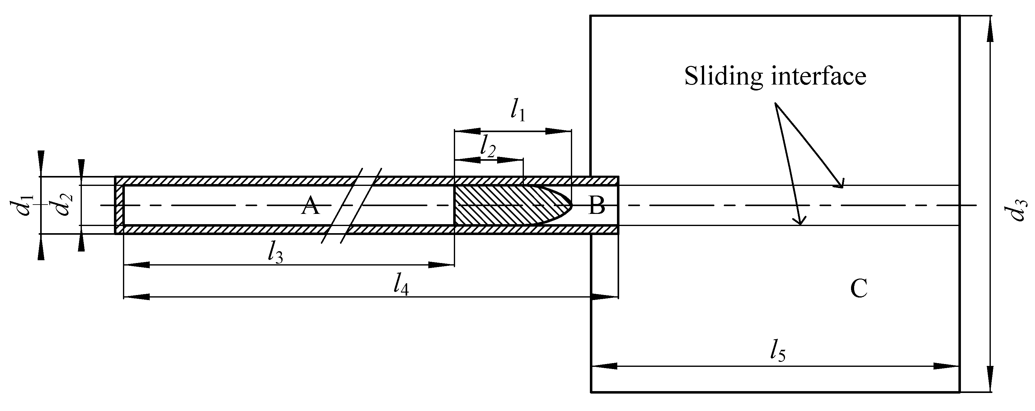
The tank gun investigated in this paper is a musket barrel. Therefore, only the translation along the bore axis is considered for the projectile. A structured mesh is adopted to avoid excessive numerical dissipation, which can be caused by unstructured meshes. The update scheme of the dynamic mesh uses a dynamic layering model. The computational domain model of the projectile motion is shown in Figure 1, The computation fluid domain is divided into three zones (zones A, B, and C). Zones A, B, and C represent the region inside the bore behind the projectile, the region inside the bore in front of the projectile, and the region outside of the bore, respectively. To perform the simulation, sliding interfaces are added to divide the computation fluid domain into a fixed mesh zone, a dynamic mesh zone for barrel recoil and a dynamic mesh zone for the projectile motion which consists of the fluid domains within the bore and extends to the domain edge along the axis. The values of the parameters in Figure 1 are shown in Table 1.
In the present work, three projectile models, namely, a flat-nosed, blunt-nosed, and cone-nosed projectiles, were studied. The relationships and differences of the dynamic characteristics of the muzzle flow field for the different nose shapes were studied. The values of the parameters of each model are given in Table 2. To enhance the accuracy of the shock wave capturing near the projectile nose and base, the mesh around these regions are locally refined. The computational meshes around each of the three different-shaped projectiles are shown in Figure 2. Through a grid independence study, it was determined that the necessary number of mesh cells in the computational fluid domain was 619,740.

2.4. Boundary Conditions and Initial Conditions

Numerical boundaries in Figure 1 are applied as follows: the barrel and the projectile apply fixed adiabatic and moving adiabatic wall boundary conditions, respectively; the edges of the C zone use a free boundary condition; the axis of the barrel is treated as symmetry axis boundary condition, and thus only the upper half of the domain is calculated due to symmetry; to reduce the effect of reflected waves caused by computational domain boundaries on the flow field, non-reflecting boundary conditions are applied at the inflow and outflow boundaries.
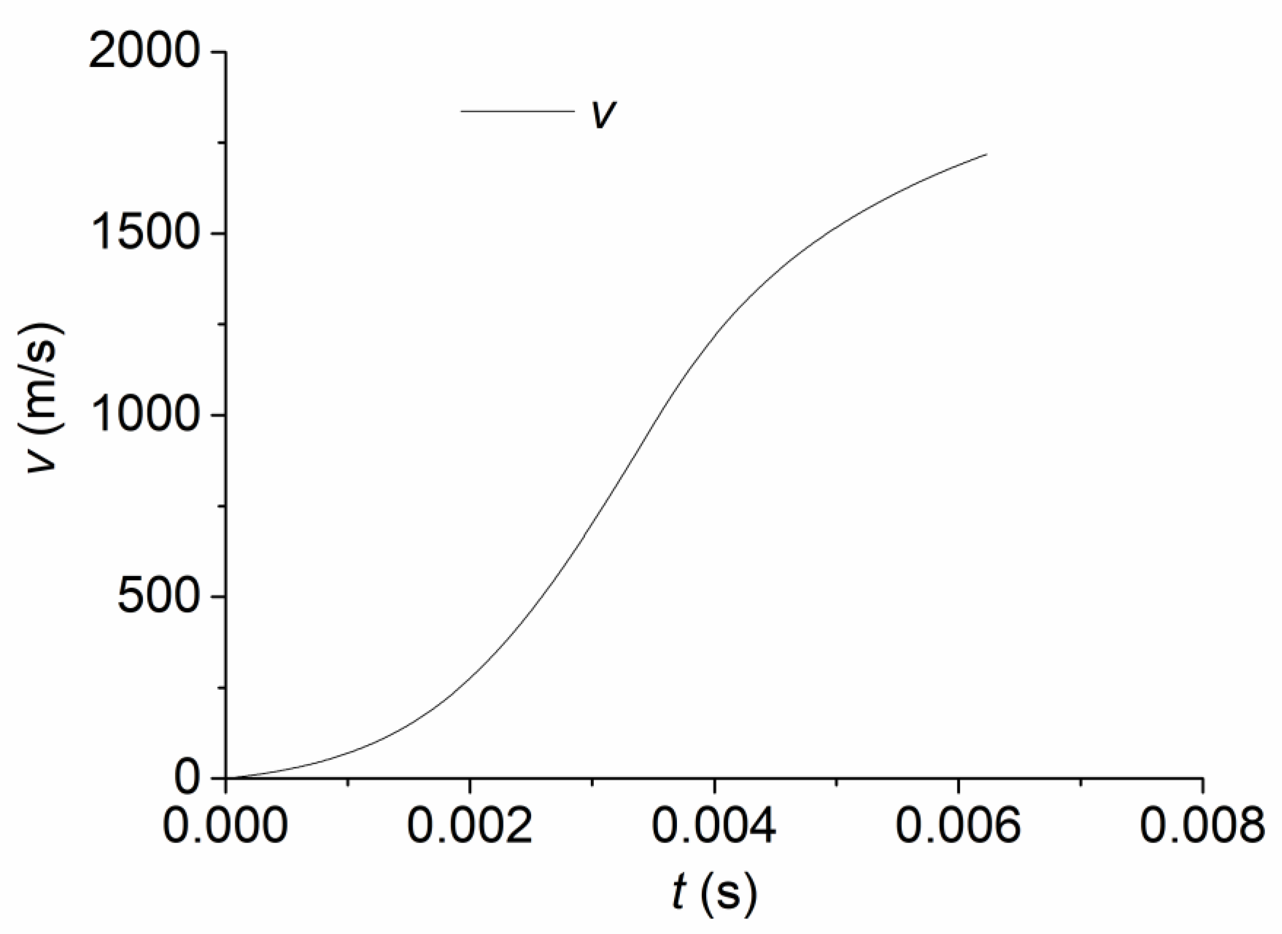
The variation of the projectile velocity moving in the bore can be derived using the interior ballistic equation. Based on this, combined with Rankine–Hugoniot relations and standard adiabatic shock relations, the characteristics of the initial flow field between the projectile nose and the muzzle, as well as the location of the projectile, can be obtained. From the projectile velocity-time curve derived from classical interior ballistics theory (as shown in Figure 3), the distance from the projectile base to the bore bottom when the initial shock wave arrives at the muzzle is obtained as l3 = 5540 mm. In the simulations, this point in time is used as the initial time (t = 0). The initial conditions of the region behind the projectile (zone A), such as the distributions of initial pressure and velocity along the bore, were obtained from the interior ballistic calculation. The initial flow field of zone B was obtained from a calculation of the flow field between the projectile front and the initial shock wave. The initial parameter distributions of zone A and zone B are shown in Figure 4. Besides, the gas in zone C is treated as an ideal gas with a temperature of T = 293 K, a pressure of Pa = 1.013 × 10⁵ Pa, and a molecular weight of 23.5. During numerical simulations, the projectile speed will subsequently vary according to Newton′s laws of motion.
For the convenience of discussion and analysis of shock-wave phenomena, in the following figures acronyms are used to identify certain phenomena. Namely, SW for shock wave, PSW for precursor shock wave, SSW for secondary shock wave, CS for contact surface, SL for shear layer, BSW for bow shock wave, LSW for leading shock wave, DSW for diffraction shock wave.

3. Comparison to Experiment

The development of muzzle flow field is primarily determined by two phenomena, namely, the diffraction of the shock wave at the muzzle and the bow shock in front of the supersonic projectile. It is difficult to capture both of these features in a single experiment. Therefore a shock-tube experiment and a projectile-flight experiment corresponding to Case 1 and Case 2, were conducted separately to validate the numerical methods and computational models used in this paper.
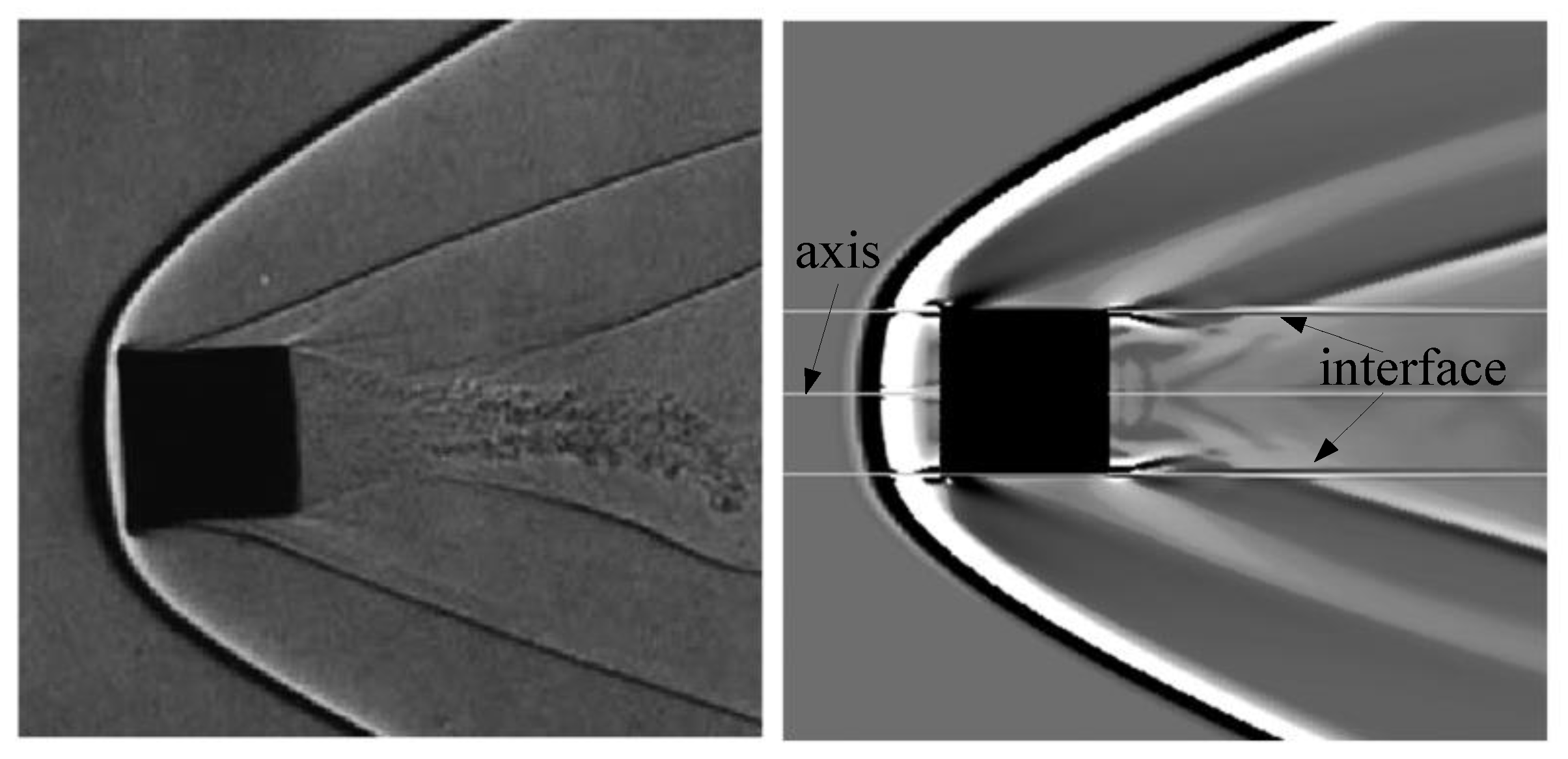
Firstly, in the shock tube experiment, the shock wave propagates from the bore to the ambient air at Ma = 1.6 and causes edge diffraction surrounding the exit. The computational domain and the boundary conditions are the same as those shown in Figure 1. The numerical Schlieren result, compared to the experimental result in the literature [21] is shown in Figure 5. The left side of the figure shows the experimental result while the right side shows the numerical result. From the figure, it can be observed that both the number and distribution of streaks agree between the two results with the exception of limited trivial differences in features. Therefore, the validity of the methods and models employed in this paper is confirmed.
Secondly, a computational model similar to the present work (barrel not considered) was used to simulate the horizontal flight of a projectile at Ma = 3.6. The numerical results are compared to experimental results in the literature [22] as shown in Figure 6. The left side of the figure shows the experimental results, and the right side shows the present numerical results. Good consistency between the numerical results and the experimental ones can be observed in the figure. Therefore, the dynamic mesh and boundary conditions are validated.

4. Calculation Results and Discussion

The following discussion considers the shock–contact surface, shock–shock, and projectile–shock interactions for different shapes of projectiles, and the generation process of the bow shock wave in detail.

4.1. Case 3: Flat-Nosed Projectile

The results sorted with respect to time for Case 3 are shown in Figure 7. In order to distinguish the contact surface and shock waves, the figure is divided along the axis of symmetry. The upper half of the figure shows the pressure contour, and the lower half shows the density contour. The numbers of contour levels are set 50 and 70 for pressure contours and density contours, respectively, in order to make the features of interest more prominent.
Figure 7a shows the muzzle flow field characteristics at t = 0.271 ms. At this time the projectile is located close to the muzzle, the airstream rushes out of the barrel and forms the first-blast around the muzzle. The high-speed airstream shears the still air outside the bore after the ejection from the muzzle and forms the SL. A low-pressure zone is then formed in the rear region, which causes the airstream to flow in reverse towards the external wall of the barrel and forms the primary vortex ring. After ejection from the muzzle, the precursor shock wave (PSW) develops nearly spherically in the air. The front of the SSW and CS develop spherically along the axis. In the radial direction, under the effect of the primary vortex ring, the edge of the SSW is entrained into the low-pressure vortex core, and the “coronal” front is formed. The CS is then entrained into the vicinity of the muzzle so that the air initially in the bore and in front of the projectile is restrained. Therefore, the area between the muzzle and the SSW forms an under-expanded region.
Figure 7b shows the muzzle flow field characteristics at t = 0.472 ms when part of the projectile has exited the muzzle and the first blast further develops in the external flow field continuously. The energy of the first-blast attenuates gradually during its propagation and replenishing energy is impeded due to the “blocking” effect of the projectile on the gas behind the projectile. Therefore, the flow characteristics begin to weaken. This weakening causes the attenuation of the primary vortex ring, declined propagation speed of the PSW, declined height of the SSW, and reduced the range of the CS. Since the movement of the projectile is faster than that of SSW, the projectile gradually catches up to the SSW and squeezes the under-expanded region, causing reduced volume and a corresponding increased density in this region. As the projectile moves, the small vortex formed around the corner point of the muzzle by the initial jet flow is absorbed by the sidewall of the projectile and moves with it. Simultaneously, the SSW deforms under the squeezing effect of the airstream in front of the projectile.
Figure 7c shows the muzzle flow field characteristics at t = 0.590 ms when the projectile base exits the muzzle and the gunpowder gas in the bore begins to exit which forms the second-blast. The second blast is composed of the LSW, the SSW and the CS. Among these, the CS of the second blast separates the airstream disturbed by the first-blast from the second-blast flow field. A non-circular wavefront is created at this moment because the second blast moves through the non-uniform flow field caused by the first blast. When the projectile nose is located in the expanded region, because of the high airstream velocity and subsonic movement of the projectile relative to the airstream, the BSW does not appear at the projectile nose. When the projectile nose rushes out of the SSW of the first blast, the movement relative to the air in front of the projectile becomes supersonic. Therefore, a detached BSW with high intensity is formed in front of the projectile nose. The SSW diffracts at the corner of the projectile, causing a drastic change in the flow field near the corner and producing a vortex. The vortex moves backwards along the projectile wall under the effect of the detached boundary layer flow induced by the BSW and drives the backward movement of the SSW. Additionally, the CS becomes rarefied during its propagation prior to reaching the BSW.
Figure 7d represents the muzzle flow field characteristics at t = 0.671 ms when the BSW is about to encounter the PSW. At this point, the second blast continues to expand. Since its axial velocity is greater than that of the projectile, the gas stream surpasses the projectile base. From Figure 7c the rightward movement of the second blast and leftward movement of the SSW of the first-blast exist along the sidewall of the projectile. These two shock waves encounter and interact with each other in Figure 7d, causing the deformation of the LSW. The CS of the first blast is distorted under the effect of the BSW.
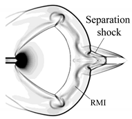
Figure 7e shows the muzzle flow-field characteristics at t = 0.736 ms. From the principle of wave superposition, the SSW of the first-blast and that of the second blast move towards each other and maintain their respective characteristics. A disturbance is created at the point of intersection that then propagates radially. The first triple-point is caused at the point of intersection by the BSW catching up with the PSW. The velocity of the gas jet flow is far greater than that of the projectile. Therefore, the airstream behind the projectile is compressed, and the projectile base shock wave is formed. When the separated flow encounters the LSW, the wavefront is distorted. Due to the high velocity of the projectile, the intensity of the BSW is high, and the velocity and pressure of the separated flow behind the wave are also high. After the separated flow of the boundary layer is formed, a positive pressure gradient is formed on the side of the projectile. This pressure gradient drives the separation point upstream until a balance is reached. A concave reversed flow occurs at the separation point, and a separation shock wave is produced at the reversed point and intersects the LSW.
Figure 7f shows the muzzle flow field characteristics at t = 0.989 ms when the LSW is about to catch up with the PSW. At this moment, the SSWs formed in the two blasts are combined and form a new shock wave. The disturbance causes the upper edge of the SL of the second-blast to twist. With the attenuation of the wave and the decline of the powder gas ejected from the bore, the velocity of the wave reduces. The SSW of the second blast is gradually separated from the projectile. When the projectile exits the shock cell, the shock wave diffracts at the tail of the projectile. This leads to the absorption of the CS of the second blast on the rear of the diffraction waves. After the LSW sweeps through the non-uniform region behind the PSW, the Richtmyer–Meshkov instability (RMI) phenomenon is induced and evolves with the movement of the LSW.
Figure 7g shows the muzzle flow field characteristics at t = 1.091 ms when the LSW merges with the PSW and interacts with the BSW to form the second triple-point. At this moment, the first triple-point vanishes. The diffraction shock waves at the projectile base gradually converge at the axis of symmetry and form a cylindrical shock focusing effect at the projectile base. The shock waves then detach from the projectile base, gradually vanish, and eventually form a stable bottle shock wave in the muzzle region at t = 1.371 ms, as shown in Figure 7h. Moreover, the separation shock wave settles at the middle of the sidewall of the projectile.
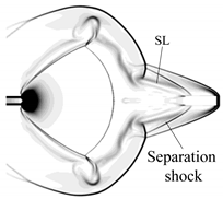
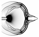
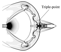
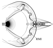
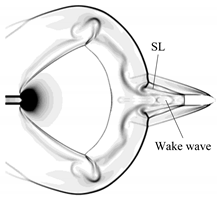
Figure 7f–h show the development of what appears to be a RMI. The RMI occurs when an interface separating two different fluids is impulsively accelerated. After the shock impact, the interface is hydrodynamically unstable and eventually turbulent mixing dominates the flow [23]. The instability is induced by the LSW. When the LSW sweeps over the CS of the first-blast in the radial direction, the instability develops very quickly and becomes significant. The interaction between the separated flow and the CS aggravates the instability to some extent. The generation of the RMI can be observed more clearly from Schlieren images, which indicate the density gradient. Table 3 shows the time sequence of Schlieren photos of the RMI development obtained using numerical simulation in time sequence, corresponding to t = 1.091 ms, t = 1.615 ms and t = 1.833 ms. It can be observed from the photos that at t = 1.091 ms, in the vicinity of the CS, only a small disturbance exists. The disturbance then develops rapidly and causes the rotation and distortion of the CS.
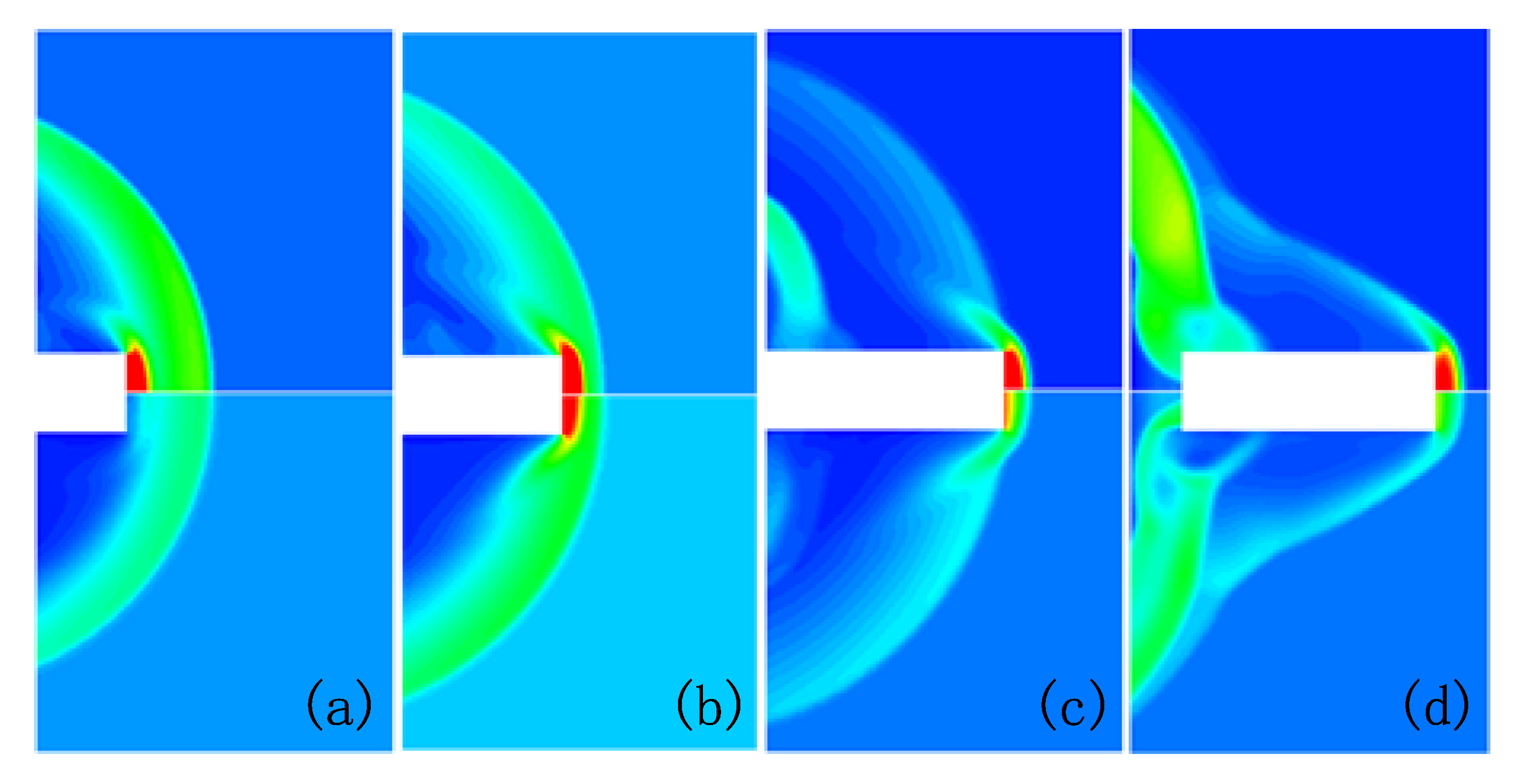
In addition, Figure 7c–f show the process of the BSW being created, chasing, and surpassing the PSW, from t = 0. 590 ms to t = 0. 989 ms. To illustrate this process more directly, the contours around the projectile nose at these time are depicted in Figure 8. The upper half and the lower half of the figure are separated by the axis of symmetry and correspond to pressure and density contours, respectively. In Figure 8a, when the projectile moves, under the flow stagnation effects, the density and the pressure rise in the region between the front of the projectile and the BSW. However, the projectile is located between the SSW and the CS. Therefore, the density and pressure of the front region of the projectile are relatively low. The maximum values of pressure and density in this region are 0.2 MPa and 1.7 kg/m3, respectively. The forward-moving projectile compresses the air between the BSW and the PSW, causing a drastic increase in density and pressure. The pressure and density reach maximum values of 5.4 MPa and 10.4 kg/m3, respectively, as shown in Figure 8b. At this moment, the BSW begins to merge with the PSW, which leads to an augmentation of the shock wave intensity. In Figure 8c, the projectile has caught up with PSW, and the intensity of the BSW reaches its maximum, corresponding to a maximum pressure of 5.7 MPa and a maximum density of 15 kg/m3 in front of the projectile. Then, the projectile flies steadily in the undisturbed air, and the expansion waves between the BSW and the projectile nose are reflected in this region and finally vanish. This process causes the formation of the BSW adapted with the relative velocity of the projectile. This implies the end of the transient process and the formation of a relatively stable flow field and the BSW in front of the projectile. The corresponding maximum pressure and maximum density in front of the projectile at this time are 4.2 MPa and 11 kg/m3, respectively. Additionally, the series of fan-shaped expansion waves caused at the inflection ahead of the projectile result in a rapid decline of the pressure behind the inflection. Therefore, the projectile nose resistance is primarily due to the BSW created ahead of the projectile.

4.2. Case 4: Cone-Nosed Projectile

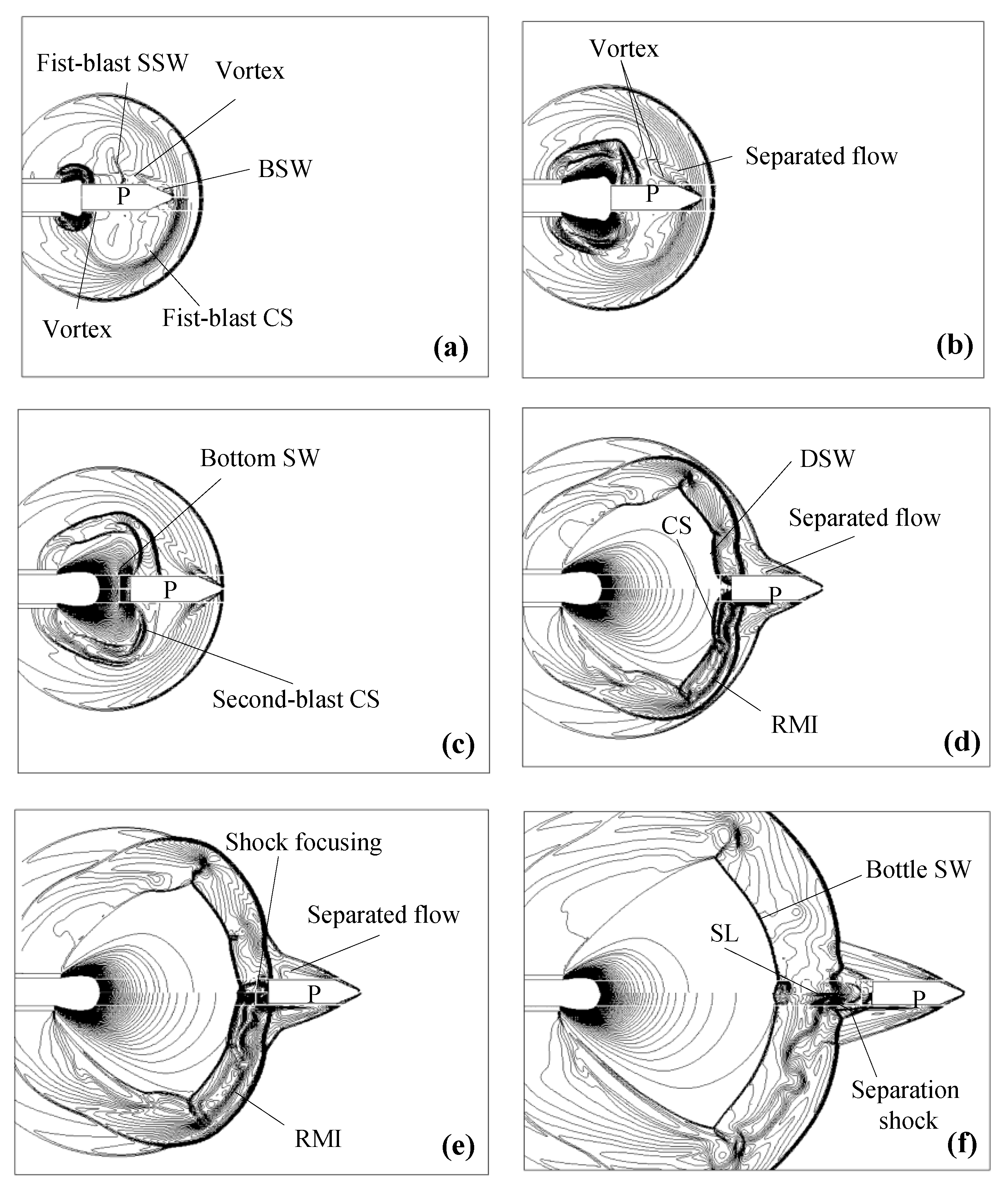
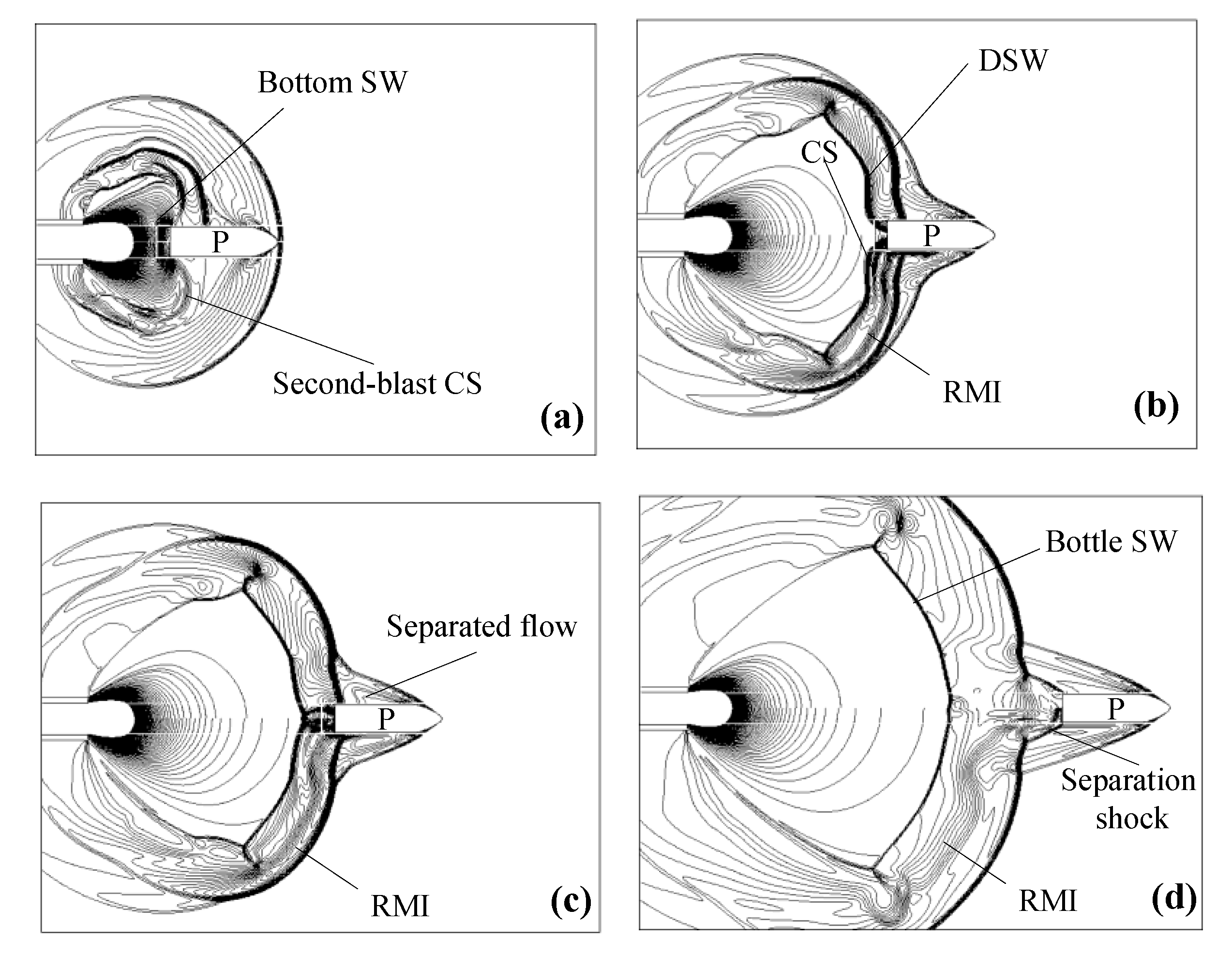
The simulation results for the cone-nosed projectile are exhibited in Figure 9 with a time sequence of pressure and density contours. The contour levels are the same as Case 3 in order to compare the cases at corresponding times. Generally speaking, the dynamic development of muzzle flow field is basically the same as Case 3. Both the first blast and the second blast appear, together with the generation of the BSW at t = 0. 590 ms, as can be seen in Figure 7c and Figure 9a. The SSW of the first blast interacts with the second blast at t = 0. 671 ms, as can be seen in Figure 7d and Figure 9b. The bottom shock wave occurs at t = 0. 736 ms, as can be seen in Figure 7e and Figure 9c. The DSW is formed at the projectile base, and the LSW approaches the PSW at t = 0. 989 ms, as can be seen in Figure 7f and Figure 9d. The shock focusing is formed at the projectile base at t = 1.091 ms, as can be seen in Figure 7g and Figure 9e. The bottle shock wave is formed at t = 1.371 ms, as can be seen in Figure 7h and Figure 9f. However, there are some discrepancies resulting from the difference in the projectile nose shape. The first of these is the interval between the SSW of the first blast and the LSW. This interval is narrower in Figure 7c, but wider in Figure 9a. The reason for this is that almost all of the separated flow of the flat-nosed projectile pushes the SSW of the first blast in the direction of the LSW, which is stronger than just the component of the separated flow of the cone-nosed projectile. Another difference is the location of the separation shock on the projectile surface. The separation shock is further downstream in Figure 7h than it is in Figure 9f. The reason for this is that a more intense separation shock wave is generated at the projectile nose in the case of the flat-nosed projectile. Therefore, the pressure gradient is increased, which promotes flow separation and causes the separation point to move upstream. This is also an important cause of the earlier emerging time of the separation shock for the flat-nosed projectile compared to the cone-nosed projectile. The last difference between the cases is the development of the RMI. The degree of instability of the cone-nosed projectile is more obvious than the flat-nosed projectile. This is because the velocity of the separated flow for the cone-nosed projectile is faster than that of the flat-nosed projectile, the CS and the separated flow interact earlier, and the intensity is increased. This can be seen in Table 3 (RMI graph).

4.3. Case 5: Blunt-Nosed Projectile

The simulation results for the blunt-nosed projectile are shown in Figure 10. Similar to the approach above, the results are compared to the numerical results of Case 3 and Case 4 at corresponding times with the same contour levels. As expected, some phenomena found in the former cases are observed again in this case. However, some differences are observed. For instance, the RMI of the blunt-nosed projectile and the flat-nosed projectile are similar, but the location and the arrival time of the separation shock on the projectile surface for the blunt-nosed projectile are the same as those of the cone-nosed projectile. This is because the BSW intensity of the blunt-nosed projectile is between those of the other two. The Schlieren photos of the last three cases are shown in Table 3. The wake waves can also be clearly identified in the Schlieren photos.
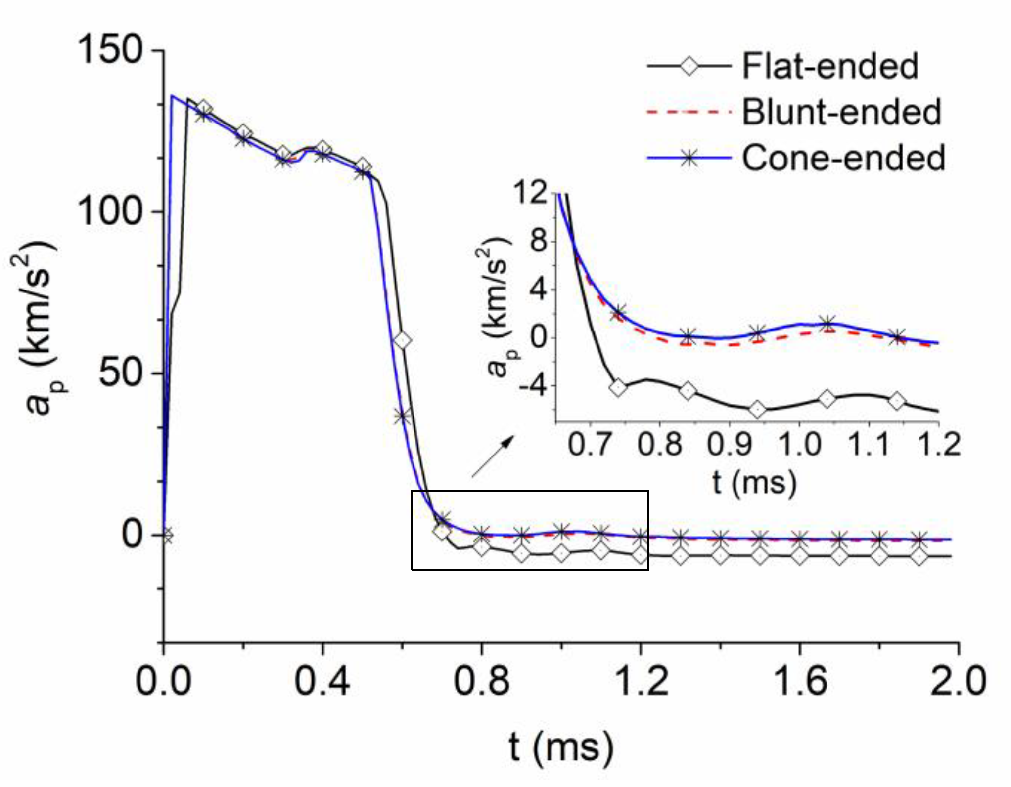
Figure 11 shows the acceleration and deceleration history of the projectiles. These results give a good insight into the axial force of the projectile. From the charts, the motion of the projectiles is almost constant between the three projectile models with only a few nuanced differences. Assuming that the projectiles are initially at a uniform motion state, the acceleration of the projectile reaches its maximum in a very short time under the given initial conditions of the flow field. Subsequently, with the decline of the bore gas energy and the increase of the resistance in front of the projectile, the acceleration of the projectile drops continuously. Eventually, the projectile flies steadily, and the acceleration approaches a constant value. It is worth noting that at t = 0.31 ms the projectile nose exits the muzzle and enters the expanded low-pressure region of the initial flow field. Next, the air resistance in front of the projectile declines and causes a slight increase in the acceleration of the projectile. In addition, the acceleration of the projectile falls dramatically between t = 0.5 ms to t = 0.7 ms. This is due to the increase in the resistance in front of the projectile caused by the substantial rise in the pressure and the density from the generation of the BSW as the projectile nose passes through the SSW. The decrease in acceleration is also due to the weakened driving effect of the gas on the projectile caused by the sharp decline in the pressure behind the projectile. This decline in pressure is caused by expansion waves as the gunpowder gas behind the projectile rushes out of the muzzle. This driving effect vanishes after the projectile base exits the SSW. It can be seen in the results that the blunt-nosed and cone-nosed projectiles are almost the same regarding variations in acceleration but are significantly different from the flat-nosed projectile. The initial conditions of the gas behind projectile are constant and, therefore, the observed differences are caused by the different resistance in front of the projectile, which is closely associated with the projectile nose area. The stable values of acceleration of the cone-nosed, blunt-nosed, and flat-nosed projectiles are −1361.08 m/s2, −1849.365234 m/s2 and −6542.96875 m/s2, respectively. In the transitional stage of the stable flight of a projectile (t = 0.7 ms to t = 1.2 ms), the fluctuations of acceleration are related to the wake wave, the DSW, the shock focusing, and interactions between SW and CS. However, the amplitude of the fluctuations is relatively low. During the simulated period, although the acceleration and deceleration are large, the duration time is very short. This leads to velocity variations, induced by the projectile nose shape, that are smaller than 0.5%.
5. Conclusions

In the present work, the effects of projectile nose shape on the muzzle flow field were considered. The shock flow induced by the projectiles was simulated by solving the two-dimensional unsteady Navier–Stokes equations using the AUSM+ discretization scheme implemented with dynamic mesh boundary conditions. From the simulated results, conclusions are drawn as follows. Firstly, the muzzle flow field is characterized by several major wave dynamic processes as follows. Two blast fields emerge one by one, and the SSW of the first interacts with that of the second. The BSW catches up and surpasses firstly the LSW and then the PSW, and the LSW catches up and surpasses the PSW. The bottom shock wave, the DSW and shock focusing emerge successively at the bottom of the projectile, causing the bottle shock wave around the muzzle. Besides, the BSW, CSs, and separated flow interact with one another. Secondly, the values of the parameters concerned, namely the RMI, the location and arrival time of the separation shock on the projectile surface, and the stable acceleration, of the blunt-ended projectile are between those of the cone-ended projectile and the flat-ended projectile. This is because that the BSW intensity of the blunt-nosed projectile is between those of the other two. Thirdly, while the acceleration and deceleration values are very large, the velocity variations as a result of the projectile nose shape are negligible as the duration time is very short. Finally, these wave dynamics processes and interactions induce vorticity and turbulence behind the projectiles, which can be clearly seen in the Schlieren images.

Author Contributions

D.X. carried out the numerical simulation; H.L. analyzed the data; Y.L. wrote the paper. All authors have read and agreed to the published version of the manuscript.

Funding

This research was funded by the 13th five-year pre-research project of weapons and equipment of China.

Acknowledgments

This paper was sponsored by the 13th five-year pre-research project of weapons and equipment of China.

Conflicts of Interest

The authors declare that they have no conflicts of interest.

Data Availability

The data used to support the findings of this study are available from the corresponding author upon request.

References

  1. Alay, E.; Skotak, M.; Misistia, A.; Chandra, N. Dynamic loads on human and animal surrogates at different test locations in compressed-gas-driven shock tubes. Shock Waves 2018, 28, 51–62. [Google Scholar] [CrossRef]
  2. Zhang, H.H.; Chen, Z.H.; Jiang, X.H.; Han, J.L. Investigation on the Blast Wave Structures of a High-speed Projectile Flying Through Different Muzzle Brakes. J. Acta Armamentarii 2012, 33, 623–629. [Google Scholar]
  3. Zhuo, C.F.; Yao, W.J.; Wu, X.S.; Feng, F.; Xu, P. Research on the Muzzle Blast Flow with Gas-Particle Mixtures Based on Eulerian-Eulerian Approach. J. Mech. 2016, 32, 185–195. [Google Scholar] [CrossRef]
  4. Jiang, Z.; Huang, Y.; Takayama, K. Shocked flows induced by supersonic projectiles moving in tubes. Comput. Fluids 2004, 33, 953–966. [Google Scholar] [CrossRef]
  5. Jiang, Z. Wave dynamic processes induced by a supersonic projectile discharging from a shock tube. Phys. Fluids 2003, 15, 1665–1675. [Google Scholar] [CrossRef] [Green Version]
  6. Jiang, X.; Fan, B.; Li, H. Numerical investigations on dynamic process of muzzle flow. Appl. Math. Mech. 2008, 29, 351–360. [Google Scholar] [CrossRef]
  7. Jiang, X.; Fan, B.; Li, H. Numerical Investigation on the transient flow induced by a high-speed projectile. J. Aerosp. Power 2008, 23, 1579–1584. [Google Scholar]
  8. Zhuo, C.; Feng, F.; Wu, X.; Liu, Q.; Ma, H. Numerical simulation of the muzzle flows with base bleed projectile based on dynamic overlapped grids. Comput. Fluids 2014, 105, 307–320. [Google Scholar] [CrossRef]
  9. Zhuo, C.; Feng, F.; Wu, X. Development process of muzzle flows including a gun-launched missile. Chin. J. Aeronaut. 2015, 28, 385–393. [Google Scholar] [CrossRef] [Green Version]
  10. Lei, H.; Wang, Z. Effect of the artillery recoil movement on muzzle flow field. J. North Univ. China 2017, 38, 36–41. [Google Scholar]
  11. Czyżewska, M.; Trąbiński, R. Symulacja ruchu pocisku w pobliżu wylotu lufy. Problemy Mechatroniki Uzbrojenie Lotnictwo Inżynieria Bezpieczeństwa 2013, 4, 95–105. [Google Scholar]
  12. Czeżewska, M.; Trębiński, R. Wpływ urządzenia wylotowego lufy na przyrost prędkości pocisku w okresie balistyki przejściowej. Problemy Mechatroniki Uzbrojenie Lotnictwo Inżynieria Bezpieczeństwa 2015, 6, 87–97. [Google Scholar]
  13. Wei, W.U.; Hou-qian, X.; Liang WA, N.G.; Rui, X. Numerical simulation of a muzzle flow field involving chemical reactions based on gridless method. Explos. Shock Waves 2015, 35, 625–632. [Google Scholar]
  14. Li, Z.; Wang, H.; Chen, J. The muzzle flow field induced by hyper-velocity projectile. J. Harbin Inst. Technol. 2017, 49, 53–59. [Google Scholar]
  15. Li, Z.; Wang, H.; Chen, J. Characteristic analysis of muzzle flow fields induced by large diameter ultra-high speed balanced gun. J. Propuls. Technol. 2017, 38, 992–997. [Google Scholar]
  16. Carson, R.A.; Sahni, O. Numerical investigation of propellant leak methods in large-caliber cannons for blast overpressure attenuation. Shock Waves 2014, 24, 625–638. [Google Scholar] [CrossRef]
  17. Ukai, T.; Kikuchi, T.; Ohtani, K.; Obayashi, S. Simultaneous visualization of surface and flow field for a projectile. J. Vis. 2013, 16, 331–340. [Google Scholar] [CrossRef]
  18. Kikuchi, Y.; Ohnishi, N.; Ohtani, K. Experimental demonstration of bow-shock instability and its numerical analysis. Shock Waves 2017, 27, 423–430. [Google Scholar] [CrossRef]
  19. Huang, Z.; Wessam, M.E.; Chen, Z. Numerical investigation of the three-dimensional dynamic process of sabot discard. J. Mech. Sci. Technol. 2014, 28, 2637–2649. [Google Scholar] [CrossRef]
  20. Liou, M.S. Progress towards an improved CFD method-AUSM+. In Proceedings of the 12th Computational Fluid Dynamics Conference, San Diego, CA, USA, 19–22 June 1995. [Google Scholar]
  21. Abe, A.; Takayama, K. Numerical simulation and density measurement of a shock wave discharged from the open end of a shock tube. JSME Int. J. Ser. 2 Fluids Eng. Heat Transf. Power Combust. Thermophys. Prop. 1990, 33, 216–223. [Google Scholar] [CrossRef] [Green Version]
  22. Jiang, X.; Chen, Z.; Fan, B.; Li, H. Numerical simulation of blast flow fields induced by a high-speed projectile. Shock Waves 2008, 18, 205–212. [Google Scholar] [CrossRef]
  23. Wang, Z.; Wang, T.; Bai, J.S.; Xiao, J.X. Numerical study of non-uniformity effect on Richtmyer-Meshkov instability induced by non-planar shock wave. Explos. Shock Waves 2019, 39, 041407-1–041407-10. [Google Scholar]
Figure 1. Computation domain model.
Applsci 10 01468 g001
Figure 2. Mesh around the projectile.
Applsci 10 01468 g002
Figure 3. Velocity-time curve of the shell moving in barrel.
Applsci 10 01468 g003
Figure 4. Velocity and pressure distribution inside the barrel at the initial moment.
Applsci 10 01468 g004
Figure 5. Comparison of numerical and experimental interferograms in the shock-tube experiment.
Applsci 10 01468 g005
Figure 6. Comparison of numerical and experimental results in the projectile flight experiment.
Applsci 10 01468 g006
Figure 7. Isopycnic (the lower half) and isobars (the upper half) for flat-ended projectile, (a) t = 0.271 ms; (b) t = 0.472 ms; (c) t = 0.590 ms; (d) t = 0.671 ms; (e) t = 0.736 ms; (f) t = 0.989 ms; (g) t = 1.091 ms; (h) t = 1.371 ms.
Applsci 10 01468 g007
Figure 8. Bow shock-wave development process ahead the projectile. (a) t = 0.590 ms; (b) t = 0.671 ms; (c) t = 0.736 ms; (d) t = 0.989 ms.
Applsci 10 01468 g008
Figure 9. Isopycnic (the lower half) and isobars (the upper half) for cone-ended projectile. (a) t = 0.590 ms; (b) t = 0.671 ms; (c) t = 0.736 ms; (d) t = 0.989 ms; (e) t = 1.091 ms; (f) t = 1.371 ms.
Applsci 10 01468 g009
Figure 10. Isopycnic (the lower half) and isobars (the upper half) for blunt-ended projectile. (a) t = 0.736 ms; (b) t = 0.989 ms; (c) t = 1.091 ms; (d) t = 1.371 ms.
Applsci 10 01468 g010
Figure 11. Acceleration and deceleration history of the projectiles.
Applsci 10 01468 g011
Table 1. Specification of 125 mm gun.
VariableValue
Outer diameter d1 (mm)176
Inner diameter d2 (mm)125
Barrel length l4 (mm)6450
Outer field lengh l5 (mm)5000
Outer field height d3 (mm)6000
Table 2. Specification of 125 mm shell.
VariableFlat-EndedBlunt-EndedCone-Ended
Projectile length l1 (mm)420420420
Cylindrical lengh l2 (mm)420300300
Inertia moment IXX (kg·m2)0.014450.014140.013669
Inertia moment IYY (kg·m2)0.12720.078280.085464
Projectile mass m (kg)7.47.47.4
Table 3. Richtmyer–Meshkov instability (RMI) Schlieren comparison.
T = 1.091 msT = 1.615 msT = 1.833 ms
flat-ended Applsci 10 01468 i001 Applsci 10 01468 i002 Applsci 10 01468 i003
cone-ended Applsci 10 01468 i004 Applsci 10 01468 i005 Applsci 10 01468 i006
blunt-ended Applsci 10 01468 i007 Applsci 10 01468 i008 Applsci 10 01468 i009