Article

Optimization and Experiment of Mass Compensation Strategy for Built-In Mechanical On-Line Dynamic Balancing System

1
School of Mechanical Engineering, Shenyang Jianzhu University, Shenyang 110168, China
2
National and Regional Joint Engineering Laboratory of High-grade Stone NC Processing Equipment and Technology, Shenyang 110168, China
*
Author to whom correspondence should be addressed.
Appl. Sci. 2020, 10(4), 1464; https://doi.org/10.3390/app10041464
Submission received: 31 December 2019 / Revised: 11 February 2020 / Accepted: 17 February 2020 / Published: 21 February 2020
(This article belongs to the Section Applied Physics General)

Abstract

:
In order to solve the problem of low precision and efficiency in the balancing process due to the movement of balance counterweights in a built-in mechanical on-line dynamic balance system, an optimization strategy for the mass compensation of the mechanical on-line dynamic balancing system is proposed, and a mass compensation optimization model is established. The optimization model takes the phase of counterweight movement as the optimization variable and the residual stress under dynamic balance as the optimization objective. Through the optimization model, the movement phase of the counterweight can be calculated, and the counterweight can be moved to a balanced position that significantly reduces the degree of unbalance. An experiment platform was built to carry out comparison experiments under different rotating speeds and unbalance levels. By comparing the residual stress, amplitude, and dynamic balancing time of the spindle before and after the balance, the accuracy of the phase of the counterweight that is calculated by the optimization model is verified. The optimized dynamic balance compensation strategy and the unoptimized were compared by experiments at different rotating speeds. The experimental results showed that, compared to the unoptimized balance, the amplitude of the spindle after optimizing balance with a dynamic balancing device can decrease by 30.39% on average, with its maximum amplitude decreasing by up 50.18%, and the balancing time can decrease by 31.72% on average, with its maximum balancing time decreasing by up to 43.86%. The research results showed that an optimization strategy can effectively improve dynamic balance efficiency and greatly reduce vibration amplitude, which provides the necessary theoretical basis for improving the running precision of the spindle system.

1. Introduction

High-end CNC(Computer Numerical Control) machine tools are essential equipment for intelligent manufacturing. In order to achieve the high-speed and high-precision intelligentization of high-end CNC machine tools, the first problem that needs to be solved is to improve their machining accuracy and efficiency. The running quality of spindle systems, which are the core components of CNC machine tools, determines the performance of CNC machine tools. However, the spindle system produces mass unbalance, which causes the machine tool to vibrate, thus seriously affecting machining accuracy due to the load, as well as the impact and wear deformation during the working process [1]. Therefore, it is of great theoretical and practical significance to study the on-line dynamic balancing technology of the spindle system [2]. The existing commercial solutions for the balancing of spindles in CNC machines include direct, indirect, and hybrid methods. The direct method achieves balance by changing the position of the center of gravity of the rotor or the center of gravity of the balancing head. There are spray-type dynamic balancing methods, liquid jet dynamic balancing devices, and de-weighting dynamic balancing devices adopt by the laser method. The indirect method indirectly adjusts the dynamic balance of the spindle via components such as actuators or bearings. This device applies a force that is equal to the magnitude of the unbalanced force on the balance head or the balance plate, and the force in the opposite direction is used to eliminate the amount of unbalance to achieve the dynamic balance of the rotor system [3]. The hybrid method is mainly balanced by a dynamic balancing head, which includes a motor-driven mechanical balancing head, a liquid jet balancing head, and an electromagnetic balancing head [4]. Among them, the motor-driven dynamic balance device mainly realizes dynamic balance by driving the movement of the counterweights; this process is a kind of hybrid method that achieves dynamic balance. Because it is small enough and can be built into a spindle system that can achieve online dynamic balancing during the operation, a motor-driven dynamic balance device is more suitable for spindle dynamic balancing than other devices. A built-in dynamic balancing device is shown in Figure 1. Therefore, in this paper, the mass compensation of the dynamic balancing of a motor-driven dynamic balance device is studied.
At present, the on-line dynamic balancing of a spindle system mainly achieves the purpose of unbalanced mass compensation by driving the mass of the built-in dynamic balance system. The core of the implementation of dynamic balancing is the efficient and accurate completion of the mass compensation. The process of more accurately calculating the dynamic balance compensation amount and more quickly achieving mass compensation are the key points to improve the accuracy and efficiency of dynamic balance. Therefore, dynamic balance control methods and mass compensation strategies for dynamic balance are becoming domestic and foreign research hotspots in recent years. Chen Lifang et al. proposed criteria for the optimal movement of counterweights and its judgment principles. A double-weight balance head without an error control algorithm can effectively improve automatic balance quality so that a motor-driven double counterweight balance head has no misalignment, no oscillation, and a short balance time [5]. Cao et al. improved a double balance disk movement control strategy that can be arbitrarily rotated in two directions relative to the axis of rotation. Two types of special cases have provided solutions that can effectively improve the quality of automatic balance [6]. Li Xiaofeng et al. deduced a high-speed flexible rotor without a test-mode modal dynamic balance method based on modal balance theory. This method solves the problem of the influence coefficient method and the modal balance method in that the need to add a test weight, and this method can effectively, accurately, and quickly obtain the magnitude and orientation of the unbalance of a flexible rotor [7]. Hong Jiang et al. combined a parametric time–frequency analysis with the holographic balance method to determine the unbalance amount and angle of a rotor [8]. Spanish scholar J.G. Mendoza Larios et al. proposed an on-line identifier method based on algebraic recognition technology. A multi degree of freedom rotation system based on the finite element method was developed to determine the magnitude of the rotor unbalance and its angular position on the rotor so that the magnitude and position of the compensation could be determined [9]. Kuen Tai Tsai simultaneously used the influence coefficient method and genetic algorithm to obtain the balance weight and angle plane of each balance so that the balance weight could be placed on multiple balance planes at the same time, which helped to shorten the time of field dynamic balance test and improve the dynamic balance efficiency [10]. Xiangbo Xu et al. proposed a synchronous current reduction approach with a variable-phase notch feedback that could identify on-line rotor unbalance, compensate rotor unbalance, and suppress harmonic vibration through the addition of discrete additional weight on two specified balance planes of the rotor [11]. Xu Juan et al. proposed a fuzzy self-tuning single neuron PID(Proportion Integration Differentiation) control method in order to improve the control efficiency and balance accuracy of rotor auto-balance, and this method had a faster response time, fewer overshoots, and fewer oscillations [12]. Xue Bing et al. proposed a sliding mode variable structure control method based on the combination approach law to control the motor inside a balancing head, and this method could effectively eliminate the vibration unbalance of a grinding wheel [13]. Fan Hongwei et al. confirmed that a self-balancing electric spindle is affected by the balance head and the speed, and they designed an electromagnetic balancing device [14]. Ma Haitao et al. designed a self-optimizing fuzzy controller based on the principle of heavy block balance [15]. Zhang Shihai et al. designed an active dynamic balancing head based on the pawl mechanism and pneumatic technology. The internal mass distribution of the balancing head could be changed to correct the unbalance of the rotor system [16]. Wang Xixuan et al. proposed an innovative on-line automatic dynamic balancing system. The rotor unbalance was balanced by the total balance vector composed of the balance mass of two or three balance disks [17]. Wang Zhen-wei proposed a hydraulic automatic balancing technology that could realize the on-line automatic balancing of a rotor without stopping its operation [18].
In summary, research on dynamic balance mass compensation has achieved certain results that have laid the foundation for the development of dynamic balancing technology. However, the problem of how to improve the balancing quality and efficiency of an on-line dynamic balance device is still an urgent problem. Therefore, this paper mainly focuses on the optimization of a mass compensation strategy that is applied to a built-in dynamic balance device of a spindle system based on current domestic and foreign research. On the basis of dynamic balance control methods, an optimized mathematical model is established, and a motion strategy of the dynamic balance mass compensation, which can achieve effective dynamic balance, is optimized. The optimized dynamic balance compensation strategy and the unoptimized one were compared through experiments at different speeds to verify the effectiveness of the optimization strategy. For high-end CNC machine tools, a mass compensation optimization strategy can effectively balance their spindle, improve the machines’ operating stability, improve machining accuracy, and reduce equipment loss, which has good engineering application value.

2. Optimization of Spindle Built-In Dynamic Balance Mass Compensation Strategy

2.1. Balance Principle

The balancing principle of the on-line dynamic balance of a spindle system mainly compensates unbalanced mass by the movement of a counterweight that can be independently driven to realize the rotation in the balance head. When the sensor detects that the unbalanced vibration amount is greater than the set threshold, the control unit drives and controls the weight to rotate until the centrifugal force generated by the two counterweights reaches the unbalance amount, and the phase of the centrifugal force is just opposite to the phase of the unbalance. The device reaches balance when the resultant vector approaches zero vector.
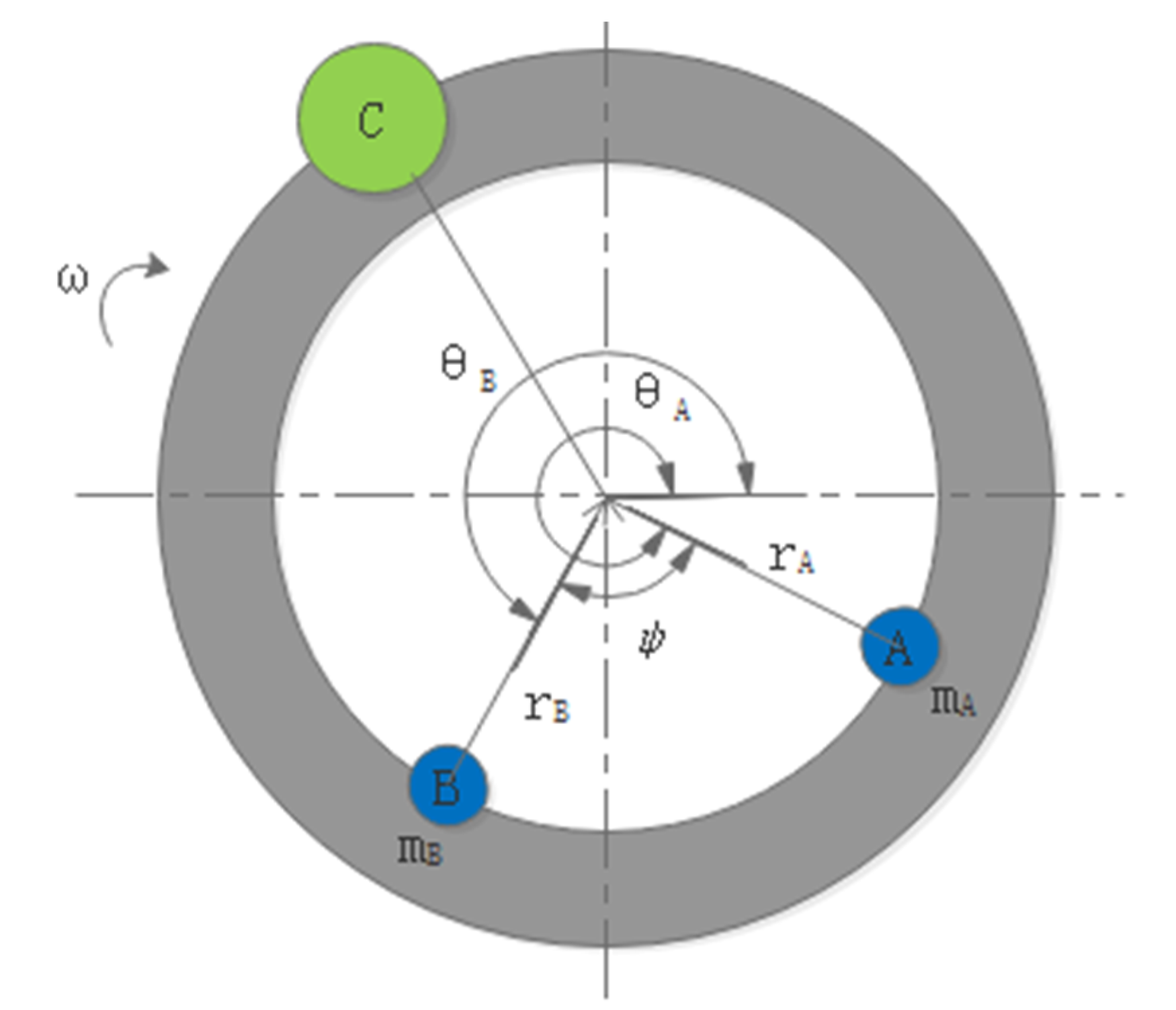
In order to make the dynamic balance principle more intuitive, the dynamic balance principle model can be further simplified. The mechanical dynamic balancing device that was used in this paper mainly solves the problem of single-plane dynamic balancing. Two counterweights with the same radius of rotation can be equivalent to two particles. In a dynamic balancing device, the mass and volume of the two counterweights are generally equal. This paper establishes a mechanical model of double counterweight balance, as shown in Figure 2. In Figure 2, A and B represent counterweights, and C represents the inherent unbalanced equivalent mass of the spindle. The counterweights represented in Figure 2 by A and B and the inherent unbalanced equivalent mass C of the spindle are equivalent to one plane. When the spindle is balanced, the following formula can be obtained:
W = F 1 2 + F 2 2 + 2 F 1 F 2 cos φ
where F 1 = m A ω 2 r A , F 2 = m B ω 2 r B , W is the inertia force of the unbalanced mass, F 1 is the mass compensated inertial force that is produced by counterweight A, F 2 is the mass-compensated inertial force that is produced by counterweight B, m A is the mass of counterweight A, m B is the mass of counterweight B, ω is the speed of the spindle, and φ is the acute angle between A and B.

2.2. Optimization Model

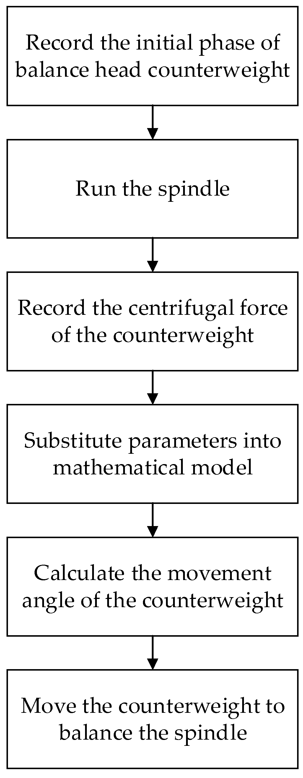
The optimization of the mass compensation strategy optimizes the moving strategy of the two counterweights, builds a mathematical model of the compensation strategy of the counterweights, and then uses the genetic algorithm to optimize the phase of the counterweights in MATLAB. A schematic flow chart is shown in Figure 3.
It can be seen from the principle of the built-in dynamic balancing device that the resultant force of the two counterweights balances the unbalanced force of the spindle when the spindle is balanced. According to the balance principle, the residual unbalanced force of the balanced spindle is taken as the optimization target, and the moving phase of the two counterweights is taken as the variable when establishing the mathematical model.
When balancing the spindle, the vector expression of the residual unbalance force of the spindle is as follows:
P = F + W
where P is the residual force after balancing the spindle, F is the resultant of the centrifugal forces of the two counterweights, W is the inertia force of the unbalanced mass, and P is the value of the residual stress. As can be seen from Formula (2), if P is small enough or close to 0, the balance is more effective. Thus, P is considered as the optimization objective.
When applying the genetic algorithm to simulate the movement strategy of two counterweights, it is necessary to establish a mathematical model for the angles of the two counterweights that are in polar coordinates. The angles φ A and φ B of the movement of the two counterweights are set as two variables, and the residual unbalance force of the spindle is the optimization target. The mathematical model is as follows:
f i n d         φ A , φ B min P ( φ A , φ B ) = ( 2 F cos ( π ( φ B φ A ) 360 θ B θ A 2 ) ) 2 + W 2 + 2 F cos ( π ( φ B φ A ) 360 θ B θ A 2 ) W cos ( π ( φ B φ A ) 360 θ B θ A 2 η ) s t .             0 φ A < 2 π                            0 φ B < 2 π
where P ( φ A , φ B ) is the residual stress, F is the resultant of the centrifugal force, W is the inertia force of the unbalanced mass, φ A is the movement angle value of counterweight A in the mechanical balance head in polar coordinates, φ B is the movement angle value of counterweight B in the mechanical balance head in polar coordinates, θ A represents the initial phase of counterweight A in the mechanical balance head, θ B represents the initial phase of the counterweight B in the mechanical balance head, and η is the phase of the inherent unbalance of the spindle.
An N-group ( φ A , φ B ) is randomly generated by computer as the initial solution of the first iteration. One can then calculate the P ( φ A , φ B ) j , m that corresponds to the initial solution of group j in the m-th iteration and select and eliminate according to the size of P ( φ A , φ B ) j , m , where j = 1, 2, 3, …, N, m = 1, 2, 3, …, H, and H is the preset number of iterations. The probability p j , m that the initial solution of the j-th group can be retained is:
p j , m = f ( φ A , φ B ) j , m i = 1 N f ( φ A , φ B ) i , m
where P ( φ A , φ B ) i , m is the P ( φ A , φ B ) corresponding to the initial solution of group i in the m-th iteration, where i = 1, 2, 3, ..., N. The cumulative probability q j , m of each p j , m is:
q j , m = l = 1 M ( p j , m ) l
where ( p j , m ) l indicates that the probability of being retained by the first calculation in the m-th iteration is p j , m and M represents the total number of times that the probability of being retained that was calculated from the initial solution of group n in the m-th iteration is p j , m . r is the random number between [0, 1], if r > q j , m , keep the j-th initial solution at the m-th iteration—otherwise, eliminate the j-th initial solution.
The original j-th set of solutions at the m-th iteration is converted to binary, and the latest solution is obtained by cross mutation. The cross operation is for each bit is in two adjacent binary numbers with a preset probability P1 random swap, and the swap position is randomly selected; the mutation operation is that each bit in the binary sequence is converted with a preset probability P2, that is the bit that is 0 becomes 1 after the conversion and the bit that is 1 becomes 0 after conversion.
The latest solution that is obtained is used as the initial solution of the m + 1 iteration; let m = m + 1 and then perform an iterative calculation. The result after H iterations is used as the final solution, and the final solution is converted into decimal output as the optimized solution. The value of the moving angle of the two counterweights is represented as polar coordinates ( φ A H , φ B H ).

3. Spindle Dynamic Balance Mass Compensation Optimization Simulation Experiment

3.1. Experiment Platform

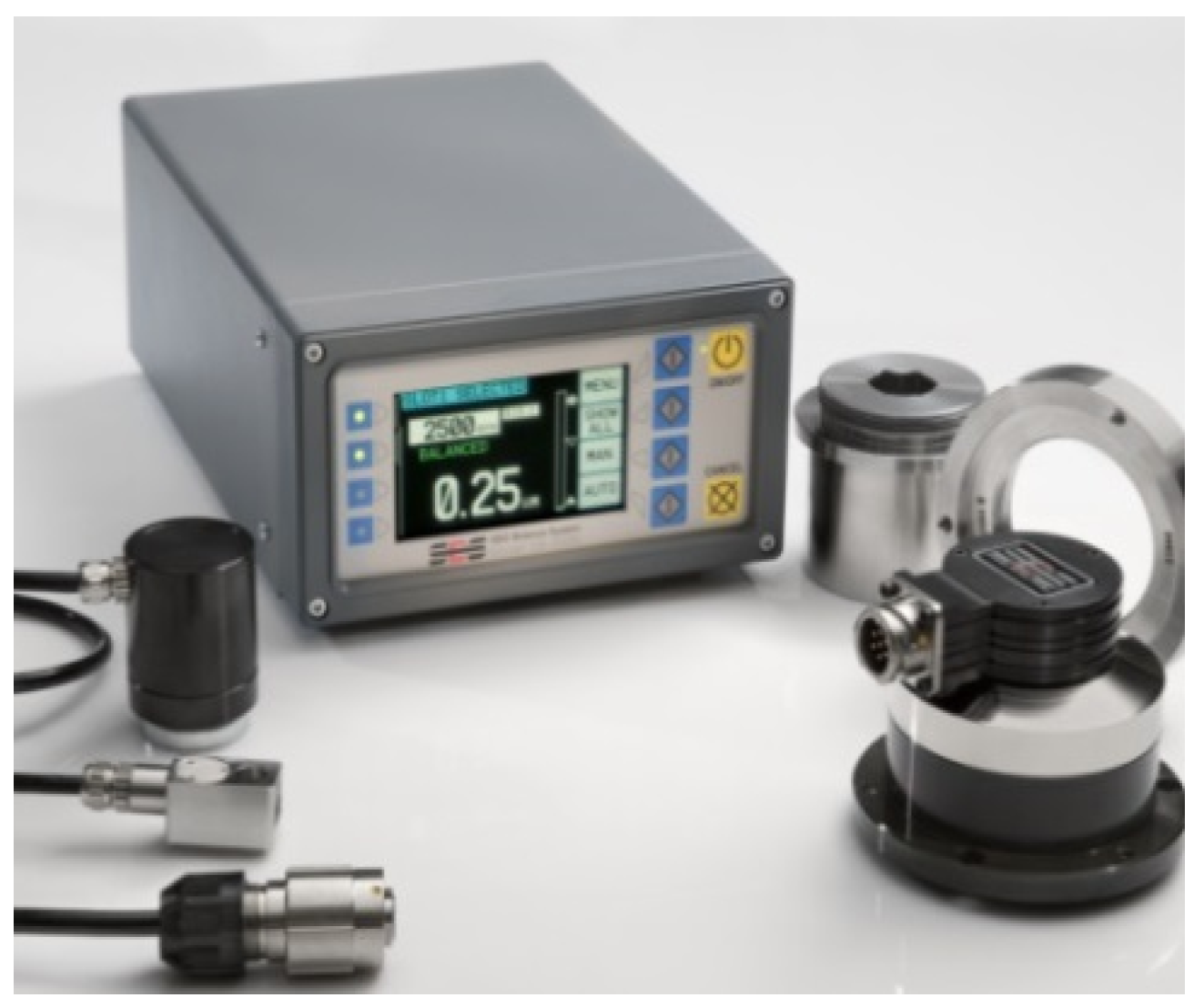
This article used a motor-driven mechanical on-line dynamic balancing device that consisted of a balancing head, a vibration sensor, a balancing head line, and a controller, as shown in Figure 4. The computer sent control commands to the control device to control the speed of the micromotor inside the balancing head. The sensor was connected to the spindle housing, detected the spindle speed pulse signal, transmitted the vibration signal to the control unit, adjusted the internal mass of the balance head, and quickly eliminated the spindle unbalance. A schematic diagram is shown in Figure 5.
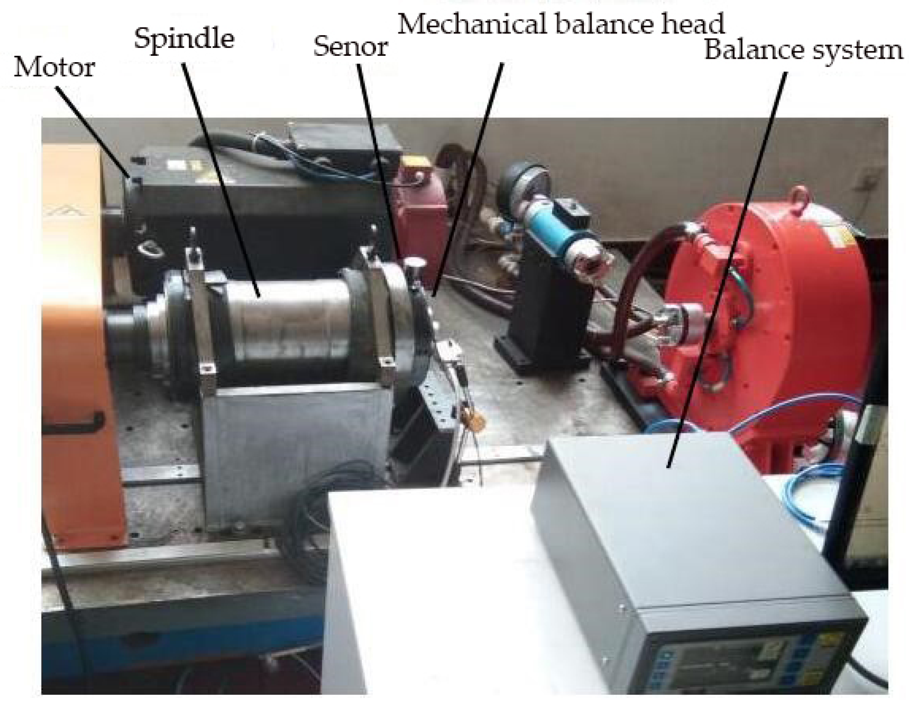
The on-line dynamic balance experiment platform consisted of a motor, a spindle, a computer control unit, a vibration sensor, a balance device, etc. The computer transmitted control commands to the control device to control the speed of the micromotor inside the balance head. The sensor was connected to the spindle housing to detect the spindle speed pulse signal, transmit the vibration signal to the control unit, and adjust the mass inside the balance head. The experiment platform is shown in Figure 6.

3.2. Simulation Experiment

The preliminary selection of six different speeds of 1000, 1500, 2000, 2500, 3000, and 3500 r/min was done to study the unbalance of the spindle. Because the spindle was balanced in the factory state, an unbalance amount was added to the front end of the spindle to simulate the unbalance of the spindle under unloaded test conditions. The proposed method was used to verify the amplitude of the spindle before and after the unbalanced balance, as well as the amplitude before and after the optimized balance. In the strategy application balance experiment, the spindle was balanced by an optimized balance adjustment method in which the proposed counterweight was moved. This process was used to check the rationality of the counterweight position that was obtained after the optimization and to compare the obtained balance effects.
The balance of the motor-driven mechanical dynamic balance head was done through a force balance method. The inherent unbalance force of the spindle is the centrifugal force generated by the unbalanced mass. Here, counterweights of 8.5, 11, and 16.5 g.mm were added the front end of the spindle, and the initial phases of unbalance amount were 180°, 120°, and 240°, respectively. In order to avoid a large amplitude of the spindle at startup, the initial phase of the counterweight was set at 0° and 180°. The results of applying the mass compensation optimization method to calculating the balance phase of the counterweight of the mechanical balancing device is shown in Table 1:
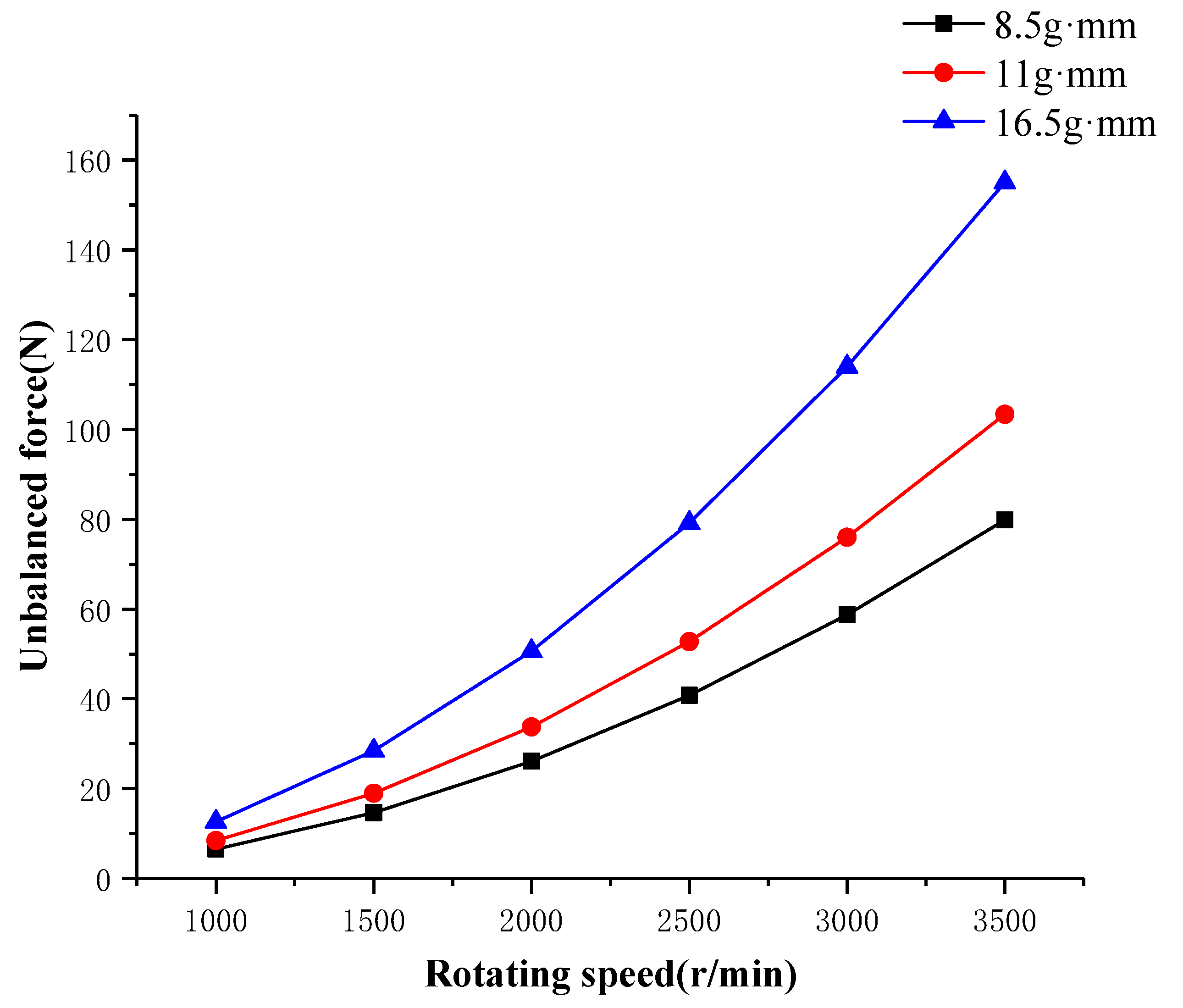
The phase that the counterweight reached in each experiment that at different speeds, masses, and phases can be seen in Table 1. At the same phase, the phases of the counterweight at different speeds were almost equal. This was because the mass of the counterweight was far greater than the unbalanced mass, and the unbalance at different speeds could be balanced within a small range. The position after the mass compensation optimization was theoretically the optimal phase of the counterweight. However, due to the complicated actual working conditions, under the automatic balance of the dynamic balancing device, the position of the counterweight could not reach the corresponding phase, so the above-mentioned accuracy could not be achieved. However, in the manual adjustment mode, the weight could be completely made. The block reached the corresponding phase. Figure 7 shows the unbalanced force of the spindle when the dynamic balancing device was unbalanced, and Figure 8 shows the unbalanced force of the spindle after balance, a force that is also known as residual force.
It can be seen from Figure 7 that the unbalanced force increased with the increase of the rotation speed. The maximum unbalanced force was 155.04 N, which was caused by an additional unbalanced amount of 16.5 g.mm, and the rotation speed was 3500 r/min. Figure 8 shows the residual force of the balanced spindle after the optimization of the control strategy. It can be seen that the residual unbalance force obviously decreased at different rotating speeds. When faster than 2500 r/min, the counterweight of the balancing device did not move to a better phase, thus leading to the residual unbalanced force ramp up under counterweights of 11 and 16.5 g.mm, and the balance ability of the balancing device had a slight decrease. However, the residual force after balancing, compared to the unbalanced inertia force, decreased by more than 90%. The minimum residual force was 0.36 N when the unbalance was 11 g.mm and the speed was 1500 r/min. The maximum residual force reached 5.58 N, which was generated when the unbalance amount was 11 g.mm and the rotation speed was 3000 r/min. The balance efficiency appeared at the maximum speed of 2500 r/min. The unbalance amount was 8.5 g.mm, the maximum balance rate was 98.9%, and the average balance rate was 95.77%.

4. Optimization Comparison Verification

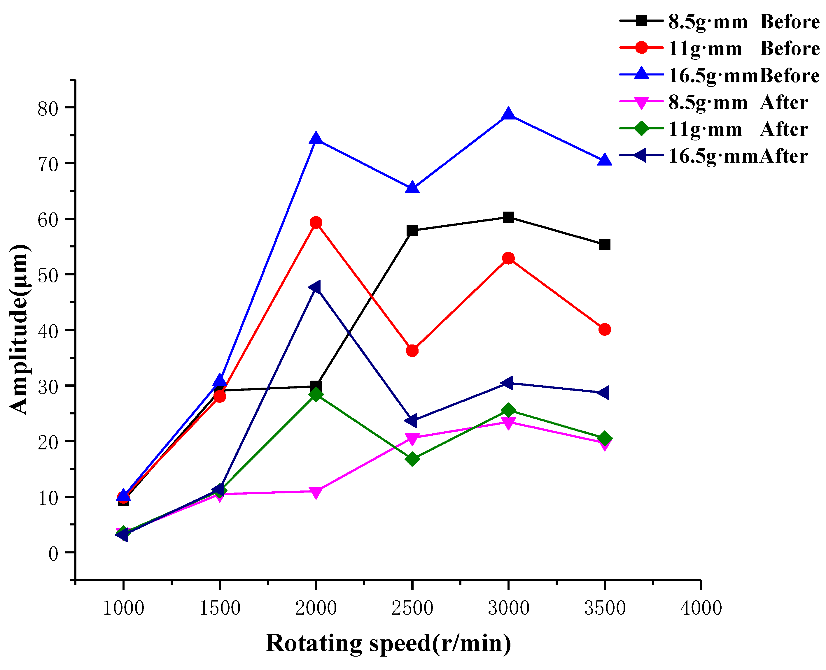
Balance amplitudes under unoptimized balance could be obtained by using the above experimental conditions with a dynamic balancing device. Figure 9 shows the amplitudes before and after the balancing of the dynamic balancing device under three different masses. The resonance of the platform had a large amplitude fluctuation at 1500 r/min. The maximum amplitude before balancing was 77.86 μm at a speed of 2500 r/min and an unbalance of 16.5 g.mm. The minimum amplitude before balancing was 7.93 μm at a speed of 1000 r/min and an unbalance of 11 g.mm. The maximum balance efficiency was 74% when the speed was 1000 r/min and the unbalance was 16.5 g.mm, and the average balance efficiency was 60.25%.
It was necessary to optimize the balance after balancing the dynamic balancing device. The initial conditions were the same as the unoptimized balance condition. The optimized balance was aimed to drive the two counterweights in the balance device to accurately reach the calculated phase. When the balance was not optimized, there was no accurate phase of the counterweight because the dynamic balance device did not have a sensor that detected the phase. The balance counterweight was driven to the specified phase by a manual mode when optimizing balance, so the motor driven mechanical dynamic balancing device had no unoptimized and optimized counterweight phase comparison.
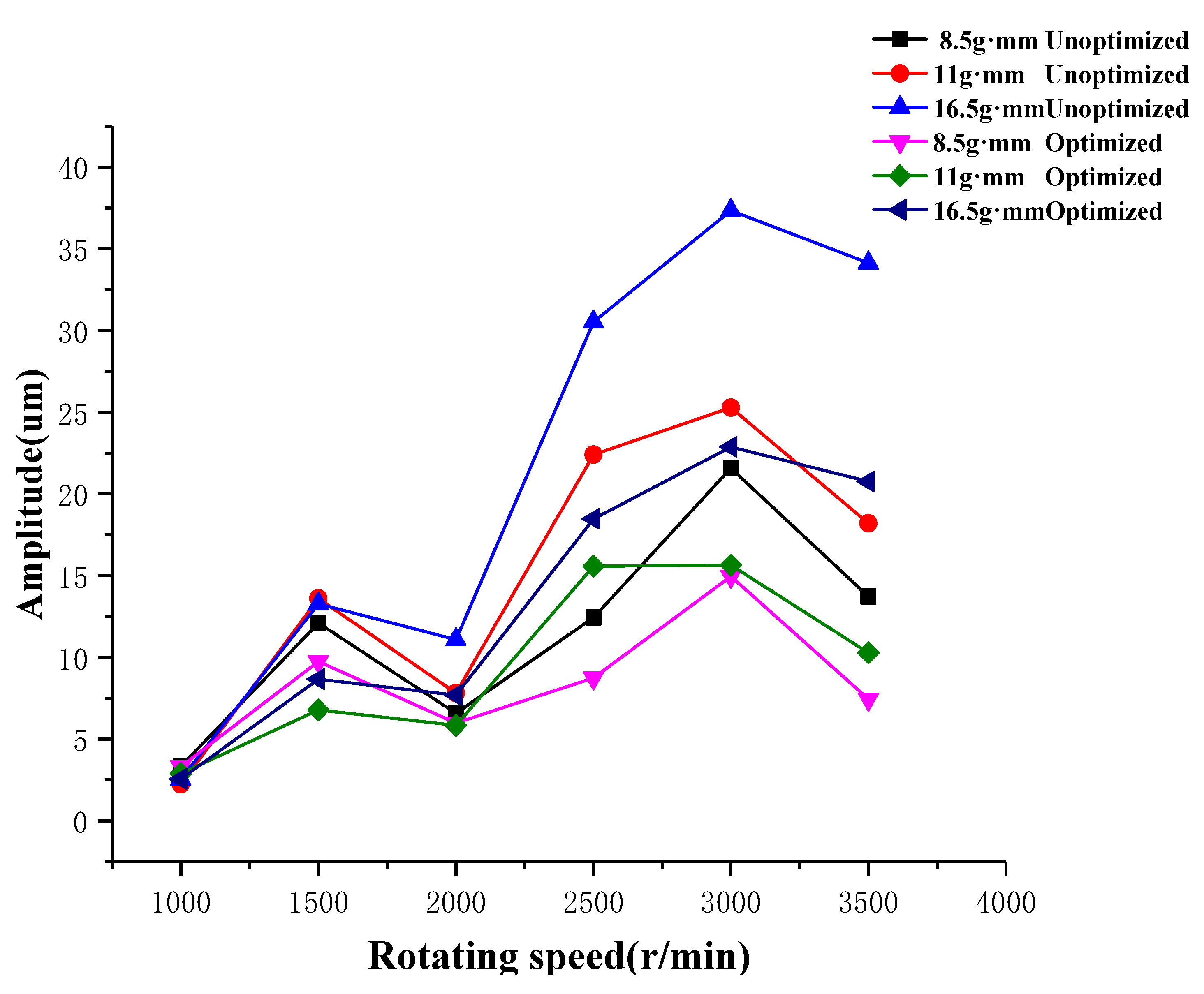
When the balance was not optimized, the phase distribution of the two counterweights was around the phase of the optimized balance, which was not as accurate as the phase of the optimized balance. In addition, the phase of the resultant force of the two counterweights and the phase of the unbalanced mass were 180° when the balance was optimized. This limited the unbalance of the spindle to the maximum. The phase of the unbalanced and optimally balanced counterweights belonged to a reasonable interval. The phase of the two counterweights had less fluctuation and a finer phase under the conditions of the three different unbalances and different speeds. According to the experimental comparison, the calculated phase was more reasonable. The largest comparison between unoptimized balance and optimized balance was reflected in the vibration amplitude of the spindle. Figure 9 is the amplitude comparison between the unoptimized balance and the optimized balance.
It can be seen from Figure 10 that the vibration amplitude of the spindle was low when the speed was low. Whether it was optimized or unoptimized, the amplitude of the spindle was not greatly reduced. However, the vibration amplitude of the spindle significantly increased as the speed increased. When the balance was not optimized, the amplitude of the spindle decreased by a certain amount. After the optimization of the balance, the amplitude of the spindle decreased compared to the unoptimized balance. The average amplitude decreased by 30.39%, and the highest amplitude decreased by 50.18%.
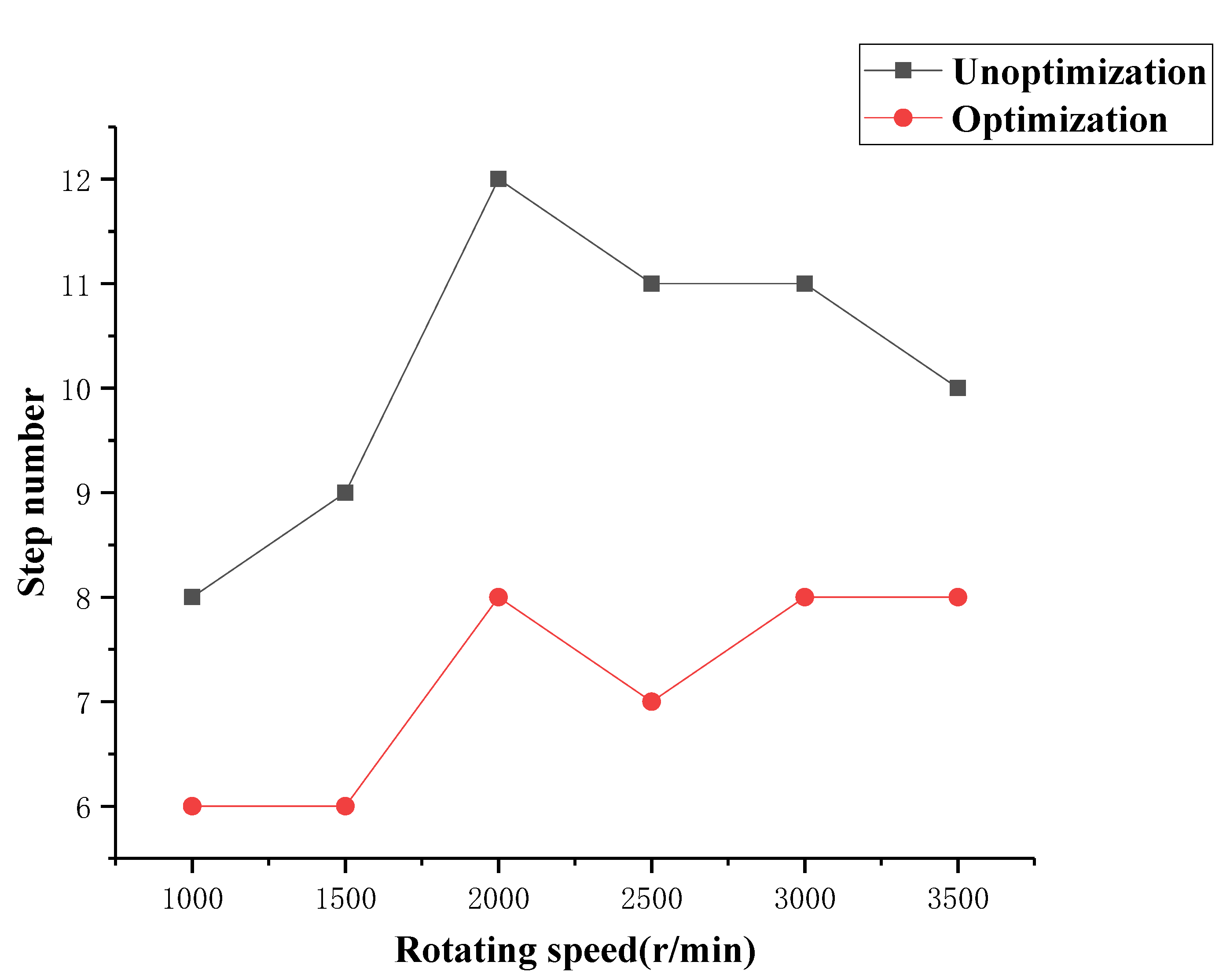
Figure 11 shows a comparison of the number of mass block movement steps before and after the balance optimization. The time for the mass block of the balancing device to move one step was 5 s. Figure 12 shows a comparison between the unoptimized balance time and the optimized balance time. Due to the aging of the equipment and the actual working conditions, both the unoptimized balance and the optimal balance time were far beyond the theoretical time of balance. When the balance was not optimized, the maximum balance time was 2000 r/min, which took 61 s and moved 12 steps. When optimizing the balance, the longest time was 3000 r/min, which took 42 s and moved 8 steps. The average balance time decreased by 31.72%, and the highest balance time decreased by 43.86%.
A motor-driven mechanical dynamic balancing device was used to verify the proposed mass compensation optimization method. The experiment results proved that the mass compensation optimization method of the counterweight improved the balance accuracy of the spindle. Compared to the unoptimized balance, the dynamic balancing device could be optimized under the optimal balance. The vibration amplitude of the spindle was further reduced, and the balance time was reduced. The precise movement of the phase of the counterweight could reduce the vibration amplitude under unoptimized balance.

5. Conclusions

The balance efficiency of the motor-driven mechanical balancing device before optimization was the largest when the rotation speed was 1000 r/min and the unbalance amount was 16.5 g.mm, with a maximum balance efficiency of 74%, and an average balance efficiency of 60.25%. After optimization, the amplitude of the spindle decreased by an average of 30.39%, and the maximum amplitude decreased by 50.18% compared to the unoptimized balance. The average balance time decreased by 31.72%, and the maximum balance time decreased by 43.86%. It can be seen from the experiments that the mass compensation model of the built-in mechanical on-line dynamic balancing system greatly improves the balancing efficiency of the single-plane balancing method. This model can calculate the optimal phase of the counterweight balance spindle through a genetic algorithm to balance the unbalanced force of the spindle and effectively reduce the vibration amplitude of the spindle. When the balance time is long and the working conditions greatly change, the moving mode of the balance head mass block can be changed by the mass compensation optimization model to improve balance time and efficiency. The accurate phase of the counterweight can quickly and effectively balance the high-precision rotating machinery of the spindle, and it can also reduce the spindle’s balance time. The optimization model of mass compensation can improve the balance accuracy and efficiency of rotating machinery, lay the foundation for further reducing the vibration and noise of equipment, reduce loss, prolong the service life, and provide the basis for the on-line dynamic balance control strategy of the spindle, which has certain engineering application values. In the future, we will do further research on the situation of unbalanced force and unbalanced moment for long spindles, and we will achieve more accurate dynamic balancing through the double-plane correction method.

Author Contributions

Conceptualization, Z.W. and K.Z.; software, B.Z.; validation, B.Z., K.Z., and G.Y.; formal analysis, Z.W., B.Z., and Z.W.; resources, Z.W. and G.Y.; data curation, B.Z.; writing—original draft preparation, B.Z.; writing—review and editing, Z.W. and B.Z.; supervision, Z.W. and B.Z. All authors have read and agreed to the published version of the manuscript.

Funding

This research was funded by the National Natural Science Foundation of China (No. 51805337, No.51675353, No.51705340), Natural Science Foundation of Liaoning Province (No. 2019-ZD-0653).

Conflicts of Interest

The authors declare no conflict of interest.

References

  1. Fan, H.W.; Jing, M.Q.; Liu, H. Review for studying on active hybrid auto-balancer of grinding wheel and motor spindle. Vib. Shock 2012, 31, 26–30. [Google Scholar]
  2. Wang, Z.; Tu, W.; Zhu, F.L. High Speed Machine Spindle On-line Dynamic Balancing Experimental Study Based on Influence Coefficie. Mach. Tool Hydraul. 2018, 46, 28–32. [Google Scholar]
  3. Li, H.W.; Xu, Y.; Gu, H.D.; Zhao, L.; Yu, S.Y. Field Dynamic Balancing Method in AMB—FIexible Rotor System. China Mech. Eng. 2008, 19, 1419–1422. [Google Scholar]
  4. Gu, C.H.; Zeng, S.; Luo, D.W.; Zhang, J.Q. Design and tests for a mechanical type of online balancing actuator. Vib. Shock 2014, 33, 151–155. [Google Scholar]
  5. Chen, L.F.; Wu, H.Q.; Wang, W.M. A study of an error-free movement control algorithm for a bi-disc balancer. J. Beijing Univ. Chem. Technol. (Nat. Sci. Ed.) 2012, 39, 89–94. [Google Scholar]
  6. Cao, Q.; Chen, L.F.; Gao, J.J. Study of bi-disc electromagnetic balancer movement control for rotor auto-balancing. J. Beijing Univ. Chem. Technol. (Nat. Sci. Ed.) 2010, 3, 121–125. [Google Scholar]
  7. Li, X.F.; Zheng, L.X.; Liu, Z.X. Theoretical and Experimental Research on Balancing of Flexible Rotors without Trial Weights. Vib. Test Diagn. 2013, 33, 65–570. [Google Scholar]
  8. Jiang, H.; Shi, Y.F.; Ran, X.F. A new rotor balancing method based on PTFA theory. Acta Technica CSAV 2017, 62, 97–107. [Google Scholar]
  9. Larios, J.G.M.; Ocampo, J.C.; Ortega, A.B.; Pliego, A.A.; Wing, E.S.G. Balanceo Automático de un Sistema Rotor-Cojinete: Identificador Algebraico en Línea del Desbalance Para un Sistema Rotodinámico. Rev. Iberoam. Automática Inf. Ind. 2016, 13, 281–292. [Google Scholar] [CrossRef] [Green Version]
  10. Kuen-Tai, T. Application of the Genetic Algorithm Method in Flexible Rotor Dynamic Balancing. Mon. J. Taipower’s Eng. 2015, 802, 18–30. [Google Scholar]
  11. Xu, X.B.; Chen, S. Field Balancing and Harmonic Vibration Suppression in Rigid AMB-Rotor Systems with Rotor Imbalances and Sensor Runout. Sensors 2015, 15, 21876–21897. [Google Scholar] [CrossRef] [PubMed] [Green Version]
  12. Xu, J.; Zhao, Y.; Jia, Z.Y.; Zhang, J.J. Rotor dynamic balancing control method based on fuzzy auto-tuning single neuron PID. IEICE Electron. Express 2017, 14. [Google Scholar] [CrossRef] [Green Version]
  13. Xu, B.; Zhang, L.N.; Zheng, P.; Xue, J.W. The New Control Strategy of Grinding Wheel Dynamic Balance Measurement and Control System. Mach. Des. Manuf. 2018, 1, 137–139. [Google Scholar]
  14. Fan, H.W.; Wu, T.Q.; Liu, H.; Jing, M.Q. Steady-state temperature field FEA of machine tool motorized spindle considering electromagnetic. Manuf. Technol. Mach. Tool 2017, 11, 88–91. [Google Scholar]
  15. Ma, H.T.; Ma, S.F.; Liu, X.Y.; Yu, Y. A dynamic balance optimal fuzzy controller for weight grinding wheel. J. Changchun Univ. 2015, 36, 163–166. [Google Scholar]
  16. Zhang, S.H.; Zhang, Z.M. Design of an active dynamic balancing head for rotor and its balancing error analysis. J. Adv. Mech. Des. 2015, 9, JAMDSM0001. [Google Scholar]
  17. Wang, X.X.; Zeng, S. The study of an on-line automatic dynamic balancing system and its dynamic balancing method when used on a flexible rotor. Reneng Dongli Gongcheng/J. Eng. Therm. Energy Power 2003, 18, 53–57. [Google Scholar]
  18. Wang, Z.W.; He, L.D.; Su, Y.R. Application of hydraulic automatic balancing technology on a fan rotor. Proc. CSEE 2009, 29, 86–90. [Google Scholar]
Figure 1. Physical picture of balance head.
Applsci 10 01464 g001
Figure 2. Mechanical model of double counterweight balance.
Applsci 10 01464 g002
Figure 3. Flowchart.
Applsci 10 01464 g003
Figure 4. Balance device diagram.
Applsci 10 01464 g004
Figure 5. Balance principle.
Applsci 10 01464 g005
Figure 6. Experiment platform.
Applsci 10 01464 g006
Figure 7. Unbalanced force before balancing.
Applsci 10 01464 g007
Figure 8. Residual force after balance.
Applsci 10 01464 g008
Figure 9. Amplitude before and after balancing without optimized balance.
Applsci 10 01464 g009
Figure 10. Comparison of balance amplitudes before and after optimization.
Applsci 10 01464 g010
Figure 11. Number of mass block moves before and after optimization.
Applsci 10 01464 g011
Figure 12. Comparison of balance time.
Applsci 10 01464 g012
Table 1. Phase of the counterweight after optimization.
Speed
/r/min
Phase of 8.5 g.mm Mass/°Phase of 11 g.mm Mass/°16.5 g.mm Mass Phase/°
ABABAB
10009826217221130350
150010226518220130348
20009826019222132345
25009926219221133347
30009826119220134346
35009926120221133346