Article

Frequency Characteristics of Multiscale Hybrid Nanocomposite Annular Plate Based on a Halpin–Tsai Homogenization Model with the Aid of GDQM

by
Mehran Safarpour
1,
Alireza Rahimi
1,
Omid Noormohammadi Arani
2 and
Timon Rabczuk
3,*
1
Department of Mechanical Engineering, Faculty of Engineering, Tarbiat Modares University, Tehran 14115-143, Iran
2
Mechanical Engineering Department, Faculty of Engineering, Shahid Chamran University of Ahvaz, Golestan Blvd., Ahvaz 61357-43337, Iran
3
Institute of Research and Development, Duy Tan University, Da Nang 550000, Viet Nam
*
Author to whom correspondence should be addressed.
Appl. Sci. 2020, 10(4), 1412; https://doi.org/10.3390/app10041412
Submission received: 15 January 2020 / Revised: 13 February 2020 / Accepted: 13 February 2020 / Published: 19 February 2020
(This article belongs to the Section Materials Science and Engineering)

Abstract

:
In this article, we study the vibration performance of multiscale hybrid nanocomposite (MHC) annular plates (MHCAP) resting on Winkler–Pasternak substrates exposed to nonlinear temperature gradients. The matrix material is reinforced with carbon nanotubes (CNTs) or carbon fibers (CF) at the nano- or macroscale, respectively. The annular plate is modeled based on higher-order shear deformation theory (HSDT). We present a modified Halpin–Tsai model to predict the effective properties of the MHCAP. Hamilton’s principle was employed to establish the governing equations of motion, which is finally solved by the generalized differential quadrature method (GDQM). In order to validate the approach, numerical results were compared with available results from the literature. Subsequently, a comprehensive parameter study was carried out to quantify the influence of different parameters such as stiffness of the substrate, patterns of temperature increase, outer temperature, volume fraction and orientation angle of the CFs, weight fraction and distribution patterns of CNTs, outer radius to inner radius ratio, and inner radius to thickness ratio on the response of the plate. The results show that applying a sinusoidal temperature rise and locating more CNTs in the vicinity of the bottom surface yielded the highest natural frequency.

1. Introduction

Annular plates are among the most important structural components widely employed in different branches of engineering like civil applications, aerospace technologies, manufacturing industry, and so on. Exploring the mechanical performance of annular plates with respect to different types of loading and boundary conditions is of great importance for engineers. In order to achieve desired thermo-mechanical properties, carbon-based materials are among the best choices to reinforce engineering structures at different length scales. Composites consists of a matrix and a macroscale reinforcement such as carbon fibers (CF) oriented in specific directions to enrich mechanical performance of the structure. Chakrapani et al. [1] used multiscale analysis to investigate the role of the fiber orientation and sequence of the laminate on the forced oscillation response of CF-reinforced composite beams. Moreover, they designed experiments confirming the accuracy of their numerical results. Emam and Eltaher [2] studied the post-buckling and buckling performance of fiber-reinforced beams exposed to a hygro-thermal environment.
Reinforcing composites with nano-fibers instead of macroscale fibers might significantly enhance the mechanical properties of the composite [3,4,5]. Maghamikia and Jam [6] employed the finite element method (FEM) to study the buckling behavior of carbon nanotube-reinforced (CNTR) annular and circular plates on the basis of third-order shear deformation theory (TSDT). They reported that the critical buckling loads obtained by their approach were lower than those obtained according to classical theory as a result of considering the shear strain terms. Tahouneh and Yas [7] applied the differential quadrature method (DQM) to study the vibration characteristics of two-dimensional continuously graded CNTR thick annular plates resting on an elastic substrate within the framework of elasticity theory. Tahouneh and Jam [8] investigated the free vibration behavior through the thickness-graded CNTR annular plates resting on an elastic foundation on the basis of elasticity theory and employing the DQM. In both studies, the Eshelby–Mori–Tanaka micromechanics approach was used to approximate the effective elastic properties of the composite. Functionally graded materials (FGM) are a very popular group of advanced materials [9,10,11,12,13]. Applying the variational differential quadrature method (VDQM) and assuming first-order shear deformation theory (FSDT), Ansari et al. [14] carried out vibration and buckling analyses of functionally graded carbon nanotube reinforced composites (FG-CNTRC) surrounded by an elastic substrate and subjected to thermal loads. Keleshteri et al. [15,16] focused on the post-buckling and large amplitude vibration characteristics of FG-CNTRC annular sector plates with integrated piezoelectric layers on the basis of FSDT considering von Karman nonlinearity and utilizing generalized differential quadrature method (GDQM). Following the same procedure, Keleshteri et al. [17] explored the large amplitude performance of FG-CNTRC annular plates coupled with piezoelectric layers resting on elastic substrate. Torabi and Ansari [18] claimed that it is necessary to develop governing equations for large amplitude vibration of FG-CNTRC annular plates in the form of general asymmetric relations accounting for initial thermal stresses to obtain accurate results. Within the framework of FSDT, Pang et al. [19] studied the vibration response of thick FG-CNTRC annular sector plates utilizing the artificial spring boundary method. The buckling performance of moderately thick FG-CNTRC annular sector plates resting on Pasternak elastic substrates and subjected to shear and in-plane loading has been analyzed by Ansari et al. [20]. Gholami and Ansari [21] carried out a nonlinear resonance analysis of FG-CNTRC annular sector plates excited by transverse harmonic loads uniformly distributed through the plate area employing VDQM and Reddy’s TSDT integrated with von Karman nonlinear strain relations. Mercan et al. [22] obtained natural frequencies of laminated thick shear deformable FG-CNTRC annular plates employing discrete singular convolution (DSC) regularized Shannon delta (RSD) and Lagrange delta sequence (LDS) kernels to the motion equations extracted from conical shell relations. Ansari et al. [23] presented a general approach to explore free vibration response of FG-CNTRC cylindrical, conical shells and annular plates by applying VDQM on the governing equations established based on FSDT and Hamilton’s principle. Considering von Karman nonlinearities in the HSDT-based axisymmetric governing equations, Ansari et al. [24] studied the vibration response of sandwich annular plates with isotropic core and FG-CNTRC interfaces embedded in elastic substrates. On the basis of FSDT, Zhong et al. [25] employed Ritz method to investigate vibration characteristics of FG-CNTRC annular, circular, and sector plates. Civalek and Baltacıoğlu [26] employed DSC to analyze free vibration behavior of CNTRC annular and annular sector plate within the framework of FSDT.
Geraphene platelets (GPLs) are an alternative to CNTs for enriching the mechanical characteristics of composite structures [27,28,29,30,31,32,33,34,35]. Within the framework of theory of elasticity, Yang et al. [36] employed the Mian–Spencer approach and carried out a three-dimensional axisymmetric thermo-mechanical bending analysis of FG-CNTRC annular and circular plates. Malekzadeh et al. [37] focused on the vibration response of functionally graded graphene-platelets reinforced composites (FG-GPLRC). Gholami and Ansari [38] utilized VDQM and Reddy’s TSDT to carry out a nonlinear asymmetric bending investigation of FG-GPLRC annular plates subjected to bi-harmonic and uniform transverse loadings.
Multiscale hybrid composites (MHC) exploit both a nanoscale as well as a macroscale reinforcement. Related articles can be classified into three main categories: Those investigating the manufacturing process, those exploring the characteristics of MHCs, and those related to the mechanical behavior of MHC structures. The article published by Thostenson et al. [39] is among the first attempts to obtain a multiscale composite using chemical vapor deposition. Song [40] introduced a novel manufacturing process called vacuum-assisted resin transfer molding (VARTM) to synthesize carbon nanotube (CNT)/aramid fiber/epoxy MHCs and reported an improvement in bending characteristics compared to aramid fiber/epoxy composite. Bekyarova et al. [41,42] designed mechanical tests to prove that CNT/CF/epoxy multiscale composites manufactured by VARTM exhibit higher shear strength and electrical conductivity compared with CF/epoxy composite. Jiang et al. [43] used electrophoretic deposition (EPD) to obtain graphene oxide/CF/polyurethane composite in order to achieve higher tensile strength. Cougo et al. [44] reviewed some manufacturing methods of MHCs with carbon-based nano-fillers such as high energy sonication [45], resin infusion technique [46], VARTM [47], and EPD technique [48,49].
Many researchers conducted experimental and theoretical investigations on the properties of MHCs, i.e., electrical anisotropy [50], microwave properties [51], electrical [52] and thermal conductivity [53], and mechanical properties [54,55] of CNT/CF/matrix composites. Using molecular dynamics, Radue and Odegard [56] studied the effect of different types of epoxy on the elasticity modulus of CNT/CF/epoxy composites. Li et al. [57] improved the thermo-mechanical properties of glass fiber/epoxy composites combined with CNTs. Other studies on mechanical properties of MHCs can be found, for instance in [58,59,60,61,62] and references therein.
Studying the mechanical behavior of MHC structures has become of great interest in recent years. Utilizing FEM within the framework of hyperbolic shear deformation theory and taking von Karman-type nonlinearity into account, Ebrahimi and Habibi [63,64] analyzed the nonlinear dynamic and low-velocity eccentric impact response of CNT/CF/polymer plates resting on elastic substrates in a thermal environment. Ahmadi et al. [65] applied FEM to study the buckling behavior of CNT/CF/polyimide composite rods subjected to axial compression. Ahmadi et al. [66] studied the forced and free vibration characteristics of CNT/CF/polymer matrix. Ebrahimi and Dabbagh [67] studied the thermo-elastic vibration of a multiscale composite beam made of CNT/CF/resin using an analytical method. Karimiasl et al. [68] utilized the homotopy perturbation method to analyze the nonlinear oscillation response of MHC doubly curved shells coupled with piezoelectric layer exposed to a hygro-thermal environment. In further studies, they [69,70] focused on nonlinear forced and free oscillation as well as post-buckling and buckling analyses of MHC doubly curved shells. In both studies, they considered GPLs/CF/polymer and CNT/CF/polymer as the MHC and employed Halpin–Tsai micromechanics to model the elastic characteristics. Based on the assumptions of classical plate theory, Ebrahimi and Dabbagh [71,72] predicted the natural frequencies and critical buckling force of CNT/CF/matrix MHC plate resting on Winkler­–Pasternak elastic foundation. Tornabene et al. [73] conducted a study dealing with free vibration performance of three-phase MHC structures made of CNT/polymer/fiber within the framework of FSDT.
To our best knowledge, free vibration performance of MHCAP made of CNT/CF/matrix, exposed to nonlinear temperature gradients and resting on Winkler–Pasternak substrate has not been explored yet, and is the focus of this manuscript. The mechanical properties of MHCAP was obtained based on the Halpin–Tsai model integrated with a micromechanical model. The governing differential equations were established through Hamilton’s principle within the framework of HSDT. The GDQM was employed to solve for the vibration response of the plate.

2. Theory and Formulation

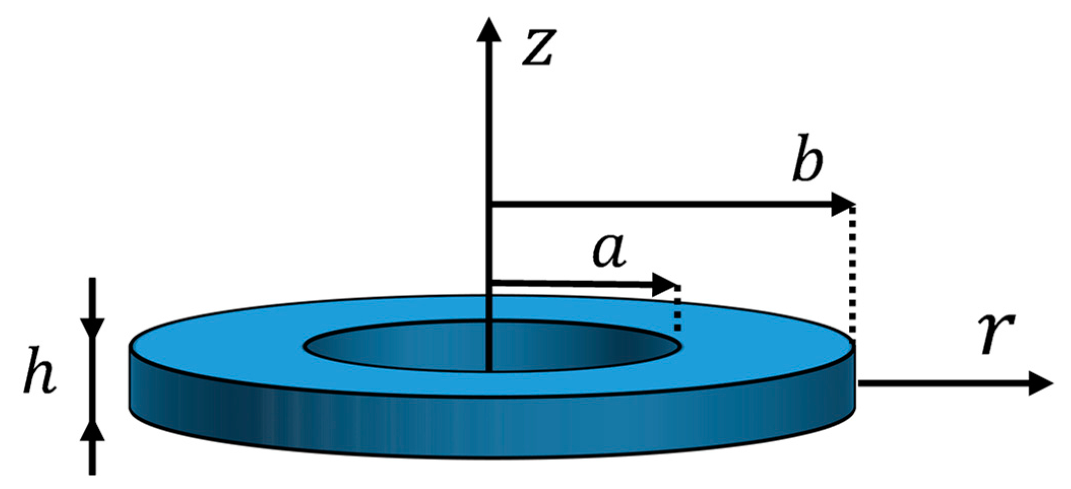
2.1. Problem Description

Let us consider the annular plate with inner radius a, outer radius b and thickness h, resting on a two-parameter elastic substrate, as illustrated in Figure 1. As mentioned before, CNTs and CF are used as nanoscale and macroscale reinforcement, respectively.

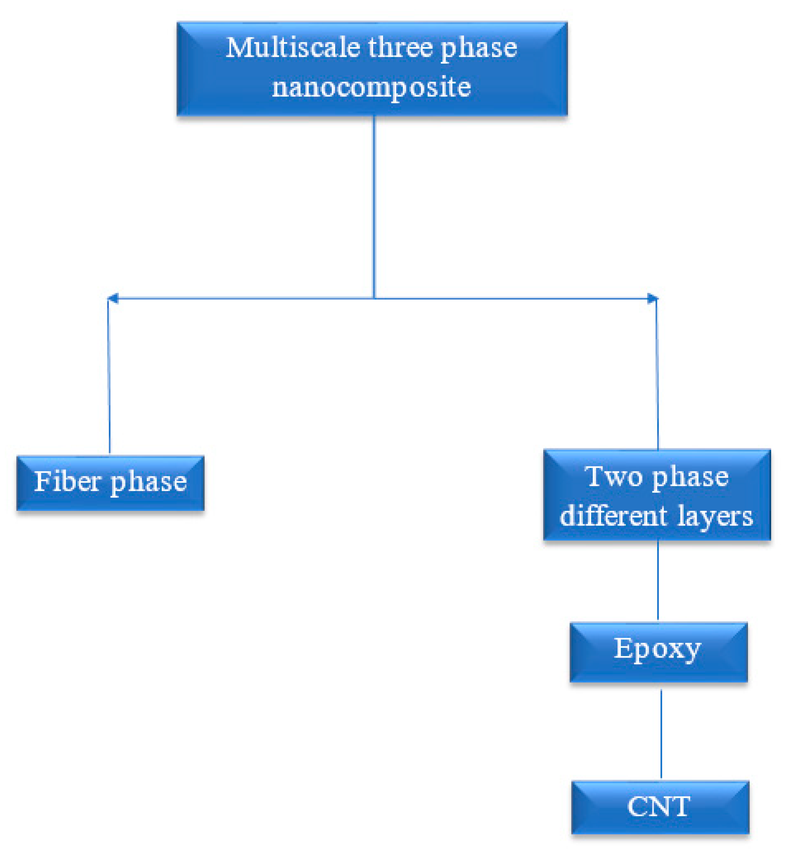
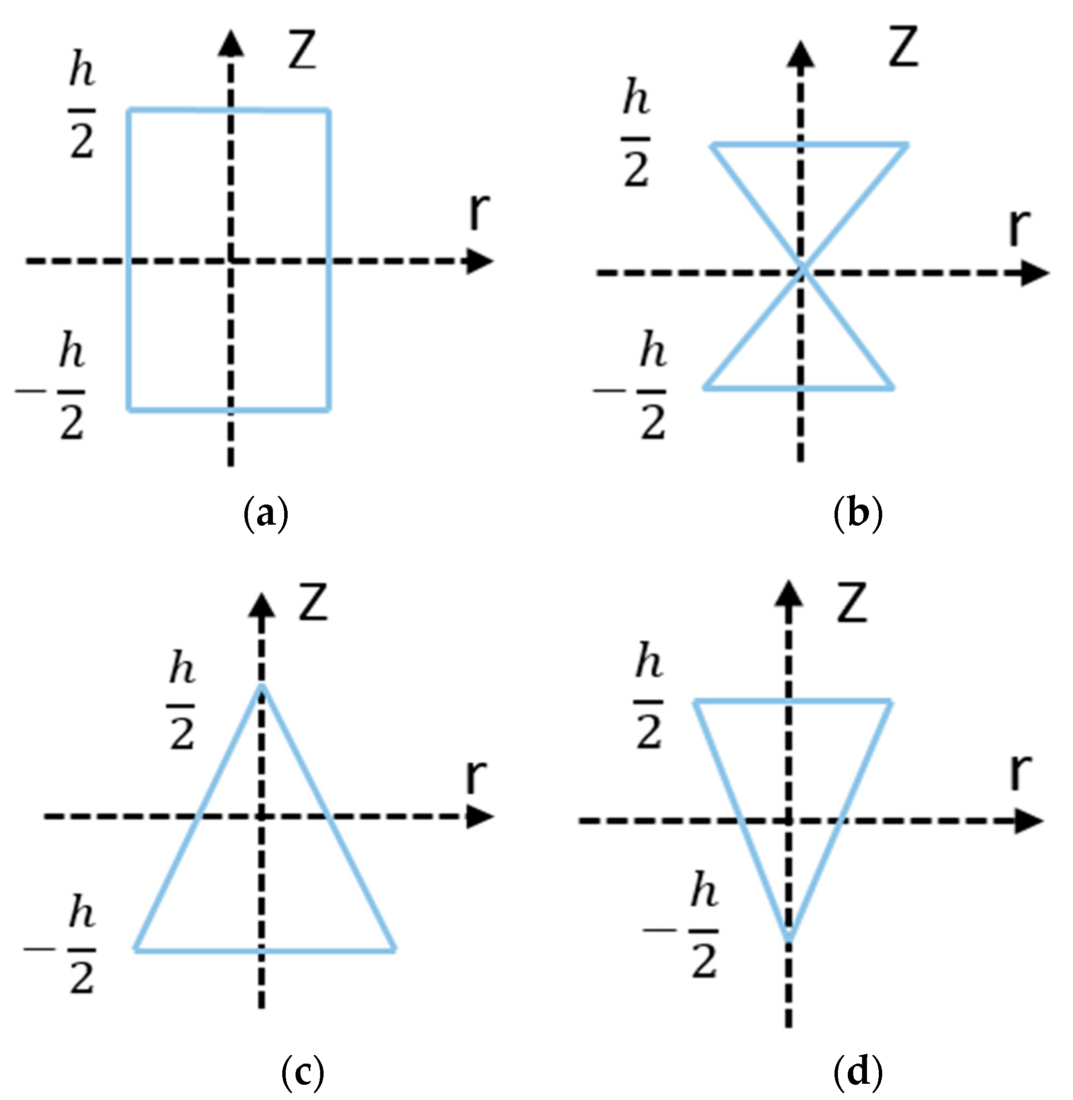
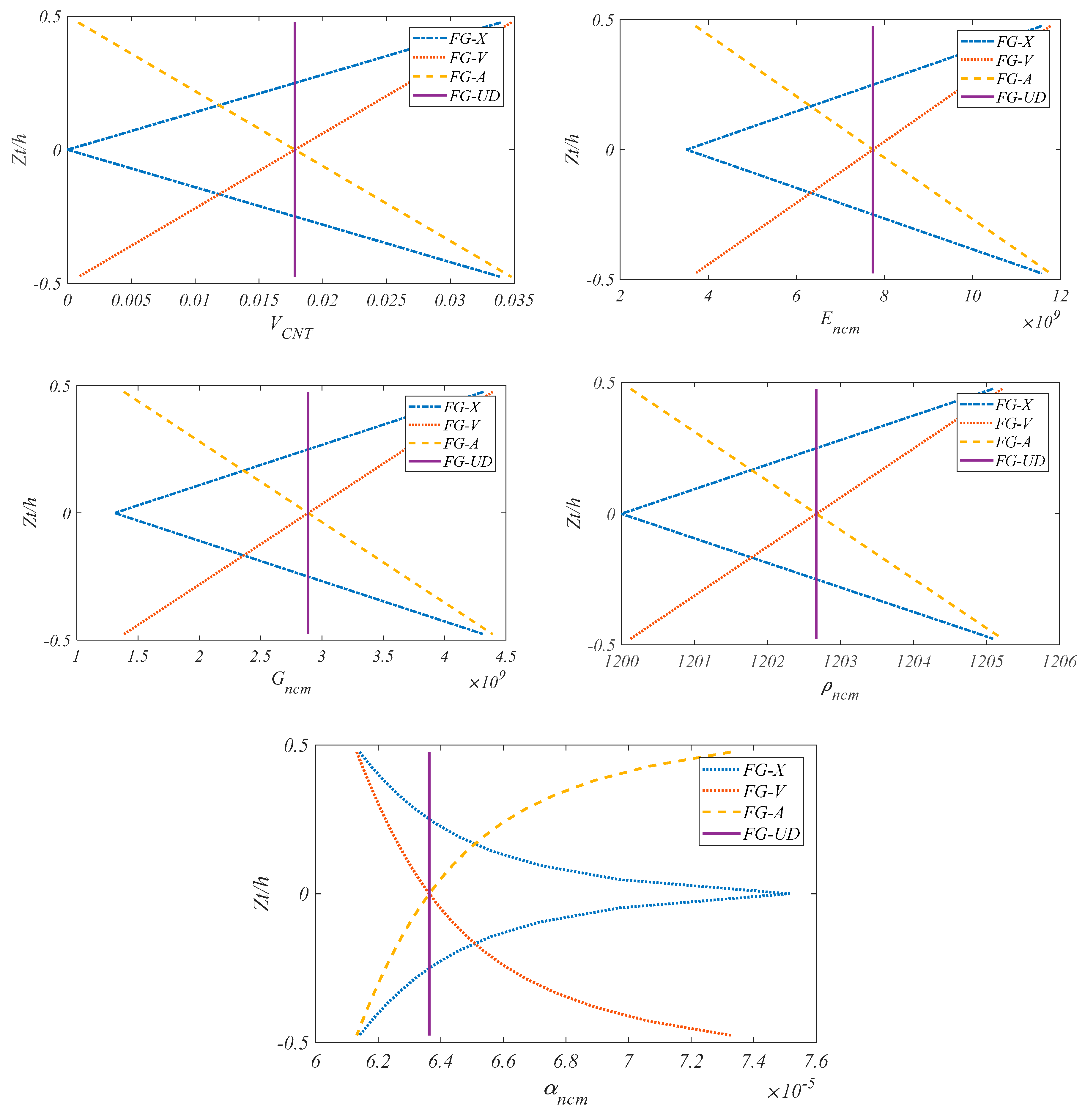
2.2. The Homogenization Process of MHC

An overview of MHC is presented in Figure 2. Accordingly, the homogenization approach was based on Halpin–Tsai model and a micromechanical theory and consisted of two main steps. First, we computed the effective properties of the composite, i.e.,
E 11 = V F E 11 F + V N C M E N C M
1 E 22 = 1 E 22 F + V N C M E N C M V F V N C M ( ν F ) 2 E N C M E 22 F + ( ν N C M ) 2 E 22 F E M 2 ν F ν N C M V F E 22 F + V N C M E N C M
1 G 12 = V F G 12 F + V N C M G N C M
ρ = V F ρ F + V N C M ρ N C M
ν 12 = V F ν F + V N C M ν N C M
where ρ ,   E ,   G and ν represent the mass density, elasticity modulus, shear modulus, and Poisson’s ratio, respectively; the superscripts NCM and F indicate ‘nanocomposite matrix’ and ‘fiber’, respectively. The sum of volume fraction of the carbon fiber V F and the volume fraction of the nanocomposite matrix V N C M is equal to 1.
V F + V N C M = 1
Second, we obtained the effective properties of the nanocomposite using the extended Halpin–Tsai micromechanics theory:
E N C M = E M ( 5 8 ( 1 + 2 β d d V C N T 1 β d d V C N T ) + 3 8 ( 1 + 2 ( l C N T / d C N T ) β d l V C N T 1 β d l V C N T ) )
in which β d d and β d l are given by
β d l = ( E 11 C N T / E M ) ( d C N T / 4 t C N T ) ( E 11 C N T / E M ) + ( l C N T / 2 t C N T ) ,     β d d = ( E 11 C N T / E M ) ( d C N T / 4 t C N T ) ( E 11 C N T / E M ) + ( d C N T / 2 t C N T )
l C N T , t C N T , d C N T , E C N T , and V C N T denoting the length, thickness, diameter, elasticity modulus, and volume fraction of CNTs, respectively. In addition, E M and V M are the elasticity modulus and volume fraction of the matrix, respectively. The volume fraction of CNTs can be calculated explicitly based on its weight fraction W C N T according to following relation
V C N T = W C N T W C N T + ( ρ C N T ρ M ) ( 1 W C N T ) .
According to subsequent relations and Figure 3, three functionally graded and one uniform pattern were considered for the distribution of CNTs through the thickness of MHCAP.
V C N T = V C N T * | ξ j | h   FG X V C N T = V C N T * ( 1 + 2 ξ j h )   FG V V C N T = V C N T * ( 1 2 ξ j h )   FG A V C N T = V C N T *   FG UD
where ξ j = ( 1 2 + 1 2 N t j N t ) h       j = 1 , 2 , , N t .
The sum of V M and V C N T as the two constituents of the nanocomposite matrix is equal to 1.
V C N T + V M = 1
The corresponding mass density, Poisson’s ratio, and shear modulus of the nanocomposite matrix can be determined as follows
ρ N C M = V C N T ρ C N T + V M ρ M
ν N C M = ν M
G N C M = E N C M 2 ( 1 + ν N C M )
Moreover, the expansion coefficients of the MHC is determined as [64]
α 11 = V f E 11 f α 11 f + V N C M E N C M α N C M V f E 11 f + V N C M E N C M
α 22 = ( 1 + V f ) V f α 22 f + ( 1 + V N C M ) V N C M α N C M ν 12 α 11
where α N C M indicates the corresponding thermal expansion coefficient of the nanocomposite matrix which is equal to [67]
α N C M = 1 2 { ( V C N T E 11 C N T α 11 C N T + V m E m α m V C N T E 11 C N T + V m E m ) } ( 1 ν N C M ) + ( 1 + ν m ) α m V m + ( 1 + ν C N T ) α C N T V C N T
Properties of functionally graded (FG) and uniform distribution of NCM along the thickness direction of the annular plate are displayed in Figure 4 and expressed according to the following relations.

2.3. Kinematic Relations

The cylindrical coordinate system (R, θ, z) and axial symmetry in loading and geometry were taken into account. With the aid of the Reddy’s shear-deformation plate theory based high-order shear deformation theory (HSDT) and symmetric deformation, the displacement fields of a circular plate are expressed by the following equations:
U ( R , θ , z , t ) = u ( R , t ) z w ( R , t ) R + ( z c 1 z 3 ) ( w ( R , t ) R + ϕ ( R , t ) ) V ( R , θ , z , t ) = 0 W ( R , θ , z , t ) = w ( R , t )
where u, w, and ϕ indicate the displacements of the midsurface in R and Z directions and rotations of the transverse normal around θ direction, respectively. It is well known that in the higher-order shear deformation theory c1 is equal to 4/3 h2. The nonzero components of the strain tensor can be decomposed as
{ ε R R ε θ θ γ R Z } = { ε R R 0 ε θ θ 0 γ R Z 0 } + z { κ R R κ θ θ κ R Z } + z 3 { κ R R * κ θ θ * κ R Z * }
where ε R R and ε θ θ indicate the corresponding normal strains in R and θ directions and γ R Z represents the shear strain in the R Z plane. Equation (18) can be rewritten as
ε R R 0 ε θ θ 0 γ R Z 0 = u R u R u z + w R , κ R R κ θ θ κ R Z = 2 w R 2 + 2 w R 2 + ϕ R 1 R w R + 1 R w R + ϕ 2 w R z + 2 w R z + ϕ z , κ R R * κ θ θ * κ R Z * = c 1 2 w R 2 + ϕ R c 1 R w R + ϕ c 1 2 w R z + ϕ z

2.4. Hamilton’s Principle

In this study, the Hamilton’s principle was employed to derive the governing equations of motion
t 1 t 2 ( δ T δ U + δ W 1 δ W 2 ) d t = 0
in which T and U stand for the kinetic energy and strain energy, respectively, and W1 and W2 denote the work done by the thermal load and the elastic substrate, respectively. Taking the first variation of the strain energy yields
δ U = 1 2 V σ i j δ ε i j d V = R 1 R 2 [ { N R R R + N θ θ R } δ u + { M R R R + M θ θ R c 1 P R R R c 1 R P θ θ + ( Q R Z 3 c 1 S R Z ) } δ ϕ + { c 1 2 P R R R 2 c 1 R P θ θ R + ( Q R Z R 3 c 1 S R Z R ) } δ w ]   d R
The resultants of the force and moment can be expressed as
{ N R R , M R R , P R R } = z σ R R { 1 , z , z 3 } d z
{ N θ θ , M θ θ , P θ θ } = z σ θ θ { 1 , z , z 3 } d z
{ Q R z , S R z } = z σ R z { 1 , z 2 } d z
The variation of the work induced by thermal gradient is given by
δ W 1 = R 1 R 2 [ N T w x δ w x ] d R
with the force resultant of the thermal loading N T
N T = h / 2 h / 2 ( Q 11 α 11 + Q 12 α 22 )   ( T T 0 ) d z
Note that three different patterns were considered for the temperature gradient across the thickness: Uniform temperature rise (UTR), power form temperature rise (PTR), and sinusoidal temperature rise (STR) [74]. As linear temperature rises are unrealistic in real applications, we studied two other conditions to finally compare the difference to the first scenario.
U T R : Δ T = T T 0
P T R : T = T 0 + Δ T ( 1 2 + z h ) β
S T R : T = T 0 + Δ T ( 1 cos π 2 ( 1 2 + z h ) ) β
while the applied work by the elastic substrate can be expressed as
δ w 2 = R 1 R 2 ( K w w δ w + K p [ ( w x ) ( x δ w ) ] )   d R
with K p and K w being the Pasternak and Winkler coefficients of the substrate, respectively. The kinetic energy and its first variation can be written as
T = A 1 2 ρ [ ( U t ) 2 + ( V t ) 2 + ( W t ) 2 ] d R dZ
δ T = R 1 R 2 ρ [ U t δ U t + V t δ V t + W t δ W t ] d R
δ T = R 1 R 2 I O 2 u t 2 I 1 2 ϕ t 2 + I 3 c 1 2 ϕ t 2 + 3 w R t 2 δ u + I 1 2 u t 2 I 2 2 ϕ t 2 + I 4 c 1 2 ϕ t 2 + 3 w R t 2 δ ϕ + c 1 I 3 2 u t 2 + c 1 I 4 2 ϕ t 2 I 6 c 1 2 3 ϕ R t 2 + 3 w R t 2 δ ϕ + c 1 I 3 3 u R t 2 c 1 I 4 3 ϕ R t 2 + I 6 c 1 2 3 ϕ R t 2 + 4 w R 2 t 2 δ w + I O 2 w t 2 δ w d R
where { I 0 , I 1 , I 2 , I 3 , I 4 , I 5 , I 6 } = h 2 h 2 ρ N C M { 1 , z , z 2 , z 3 , z 4 , z 5 , z 6 } d Z represent the mass inertias.
Substituting Equations (22), (26), (31), and (34), into Equation (21) yields the Euler–Lagrange equations of MHCAP
δ u : N R R R N θ θ R = I 0 2 u t 2 + I 1 2 ϕ t 2 c 1 I 3 ( 2 ϕ t 2 + 3 w R t 2 )
δ w : c 1 2 P R R R 2 c 1 R P θ θ R + Q R z R 3 c 1 S R z R K W w     + K P 2 w R 2 N T 2 w R 2 = c 1 I 3 3 u R t 2 + c 1 I 4 3 ϕ R t 2     c 1 2 I 6 ( 3 ϕ R t 2 + 4 w R 2 t 2 ) + I 0 2 w t 2
δ ϕ : M R R R c 1 P R R R M θ θ R + c 1 R P θ θ Q R z + 3 c 1 S R z = I 1 2 u t 2 + I 2 2 ϕ t 2     c 1 I 4 ( 2 ϕ t 2 + 3 w R t 2 ) c 1 I 3 2 u t 2 c 1 I 4 2 ϕ t 2 + c 1 2 I 6 ( 2 ϕ t 2 + 3 w R t 2 )
The boundary conditions are given as
δ u = 0     or     N R R n R = 0 δ w = 0     or     [ c 1 P R R R c 1 P θ θ R + Q R Z 3 c 1 S R Z K P w R + N T w R ] n R = 0 δ ϕ = 0     or     [ M R R c 1 P R R ] n R = 0

2.5. Governing Equations

The corresponding stress–strain relation of orthotropic composites can be written as
{ σ R R σ θ θ τ R Z } = [ Q ¯ 11 Q ¯ 12 0 Q ¯ 12 Q ¯ 22 0 0 0 Q ¯ 55 ] { ε R R ε θ θ γ R Z }
with
Q ¯ 11 = Q 11 cos 4 θ + 2 Q 12 sin 2 θ cos 2 θ + Q 22 sin 4 θ Q ¯ 12 = ( Q 11 + Q 22 ) sin 2 θ cos 2 θ + Q 12 ( sin 4 θ + cos 4 θ ) Q ¯ 22 = Q 11 sin 4 θ + 2 Q 12 sin 2 θ cos 2 θ + Q 22 cos 4 θ Q ¯ 55 = Q 55 cos 2 θ
θ being the orientation angle and with
Q 11 = E 11 1 ν 12 ν 21 , Q 12 = ν 12 E 22 1 ν 12 ν 21 , Q 22 = E 22 1 ν 12 ν 21 , Q 55 = G 12
By integrating Equation (40) over the thickness and substituting the obtained resultants into Equations (35)–(37), the governing equations of the MHCAP are obtained as
δ u : A 11 2 u R 2 + B 11 2 ϕ R 2 D 11 c 1 2 ϕ R 2 + 3 w R 3 + A 12 R u R + B 12 R ϕ R D 12 c 1 1 R ϕ R + 1 R 2 w R 2 A 12 R u R + B 12 R ϕ R D 12 c 1 R ϕ R + 2 w R 2 A 22 R 2 u + B 22 R 2 ϕ D 22 c 1 R ϕ R + 1 R w R = I 0 2 u t 2 + I 1 2 ϕ t 2 I 3 c 1 2 ϕ t 2 + 3 w R t 2
δ w : c 1 D 11 3 u R 3 + E 11 3 ϕ R 3 G 11 c 1 3 ϕ R 3 + 4 w R 4 + c 1 D 12 R 2 u R 2 + E 12 R 2 ϕ R 2 G 12 c 1 1 R 2 ϕ R 2 + 1 R 3 w R 3 c 1 R D 12 2 u R 2 + E 12 2 ϕ R 2 G 11 c 1 2 ϕ R 2 + 3 w R 3 c 1 R D 22 R u R + E 22 R ϕ R G 22 c 1 1 R ϕ R + 1 R 2 w R 2 + A 55 3 C 55 c 1 ϕ R + 2 w R 2 3 c 1 C 55 3 E 55 c 1 ϕ R + 2 w R 2 K W w + K P 2 w R 2 N T 2 w R 2 = c 1 I 3 3 u R t 2 + c 1 I 4 3 ϕ R t 2 c 1 2 I 6 3 ϕ R t 2 + 4 w R 2 t 2 + I 0 2 w t 2
δ ϕ : B 11 2 u R 2 + C 11 2 ϕ R 2 E 11 c 1 2 ϕ R 2 + 3 w R 3 + B 12 R u R + C 12 R ϕ R E 12 R c 1 ϕ R + 2 w R 2 c 1 D 11 2 u R 2 + E 11 2 ϕ R 2 G 11 c 1 2 ϕ R 2 + 3 w R 3 c 1 D 12 R u R + E 12 R ϕ R G 12 R c 1 ϕ R + 2 w R 2 1 R B 12 u R + C 12 ϕ R E 12 c 1 ϕ R + 2 w R 2 1 R B 22 u R + C 22 ϕ R E 22 c 1 ϕ R + 1 R w R + c 1 R D 12 u R + E 12 ϕ R G 12 c 1 ϕ R + 2 w R 2 + c 1 R D 22 u R + E 22 ϕ R G 22 c 1 ϕ R + 1 R w R A 55 3 C 55 c 1 ϕ + w R + 3 c 1 C 55 3 E 55 c 1 ϕ + w R = I 1 2 u t 2 + I 2 2 ϕ t 2 I 4 c 1 2 ϕ t 2 + 3 w R t 2 c 1 I 3 2 u t 2 c 1 I 4 2 ϕ t 2 + I 6 c 1 2 2 ϕ t 2 + 3 w R t 2
with { A i j , B i j , C i j , D i j , E i j , F i j , G i j } = h 2 h 2 Q ¯ i j { 1 , z , z 2 , z 3 , z 4 , z 5 , z 6 } d z .

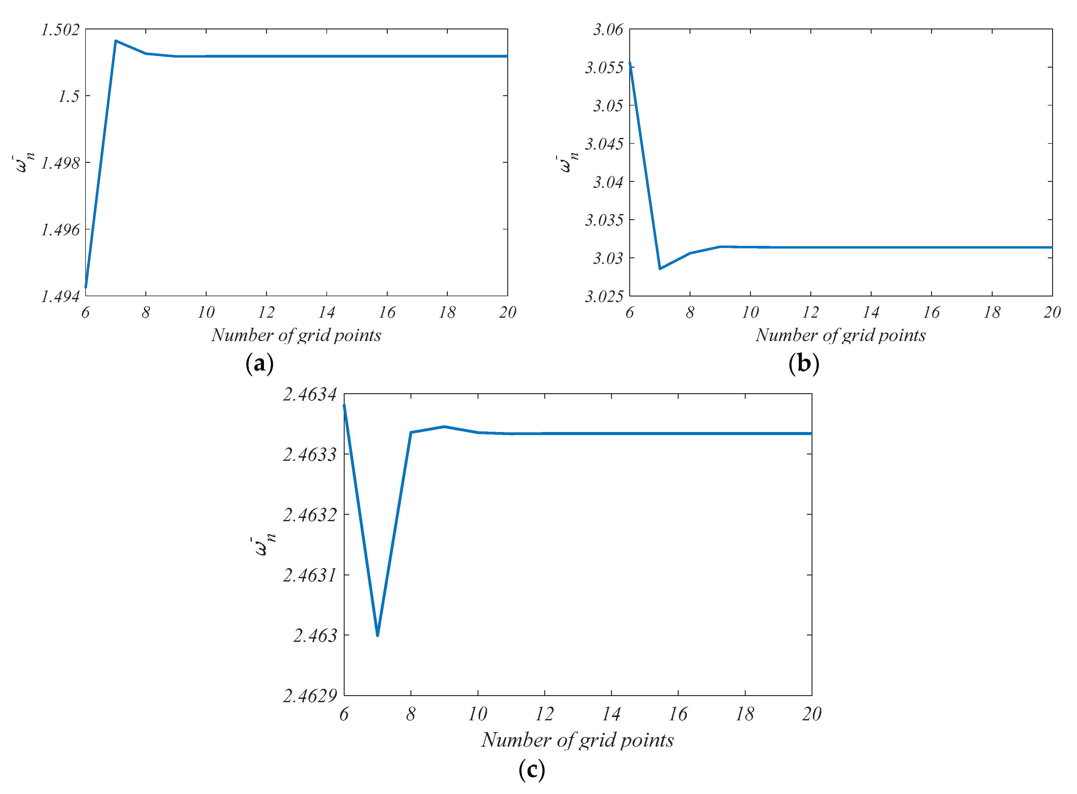
3. Solution Procedure

Numerous computational methods have been introduced to solve differential equations, such as FEM [75], Ritz method [76], deep collocation method [77], etc. In this paper, we employed the differential quadrature method (DQM), which was proposed by Bellman et al. [78,79] in the 1970s. In DQM, the results depend on the numbers of grid points. As in any computational method, choosing the optimal numbers of grid points is of high importance. Shu [80] proposed an efficient approach to determine the weighting coefficients for an infinite number of grid points which is known as generalized differential quadrature method (GDQ). Shu and Richards [81] applied a domain decomposition method which can be implemented in multidomain problems. In GDQ, the approximate rth derivative of f(x) is determined as
r f ( x ) R r | x = x p = j = 1 n g i j ( r ) f ( R i )
with n indicating the number of distributed points along the x-axis. The weighting coefficients C i j are acquired from the first-order derivative as
g i j ( 1 ) = M ( R i ) ( R i R j ) M ( R j ) i , j = 1 , 2 , , n      and      i j g i j ( 1 ) = j = 1 , i j n C i j ( 1 ) i = j
with
M ( R i ) = j = 1 , j i n ( R i R j )
For higher-order derivatives, the weighting coefficients are determined through the following relations
g i j ( r ) = r [ g i j ( r 1 ) g i j ( 1 ) g i j ( r 1 ) ( R i R j ) ] i , j = 1 , 2 , , n , i j     and     2 r n 1 g i i ( r ) = j = 1 , i j n g i j ( r ) i , j = 1 , 2 , , n     and     1 r n 1
In this study, a non-uniform set of grid points was selected [82]
R j = a + b a 2 ( 1 cos ( ( j 1 ) ( N j 1 ) π ) )        j = 1 , 2 , 3 ,   , N j
It can easily be shown that, after some algebra, we obtained the discrete system of equations as
{ [ [ M d d ] [ M d b ] [ M b d ] [ M b b ] ] ω 2 + [ [ K d d ] [ K d b ] [ K b d ] [ K b b ] ] } { δ d δ b } = 0
where the subscripts d and b represent the domain and boundary grid points, respectively, while δ refers to the displacement vector. The natural frequency of the MHCAP was normalized
ω ¯ n = ω n b 2 ρ m E m

4. Numerical Results and Discussion

Subsequently, we present a comprehensive parameter study to quantify the effects of various parameters on the free vibration response of MHCAP. The geometrical and material characteristics of the constituent materials can be found in Table 1 [64].

4.1. Verification

In order to verify the present approach, the nondimensional natural frequency of the annular plate obtained in this study was compared with those reported in [83] for different axisymmetric vibration modes, thickness to outer radius ratios h/b, inner radius to outer radius ratio a/b, and three boundary conditions (see Table 2, Table 3 and Table 4). The discrepancy between our results and the results of [83] came from the difference in the shear deformation theory [83] and HSDT here. Nonetheless, the discrepancy between the results decreased with increasing modes, and h/b and a/b ratios.

4.2. Vibration Study

The vibration studies can be divided into two parts. First, we studied the influence of different parameters (such as the geometric ratios of the plate, distribution patterns of CNT, volume fraction of carbon fibers, weight fraction of CNT, temperature gradient, etc.) on the natural frequencies of the MHCAP. Their effect on the vibration performance of the system was important for the design of such structures. Then, the sensitivity of the vibration response to nonlinear temperature gradients are presented and discussed.

4.2.1. Parametric Vibration Study

Table 5 shows the effects of the distribution patterns and CNT weight fraction on the nondimensional natural frequency of MHCAP. The plate based on FG-A (shown in Figure 3c) exhibited the best vibration response among the CNT patterns. Increasing the volume fraction of carbon fibers also yielded higher frequencies.
The vibration results obtained by GDQM are diagramed in Figure 5 for various numbers of grid points and different boundary conditions. According to the figures, choosing N = 10 as the number of grid points provided adequate accuracy to the results.
Figure 6 depicts the effects of the outer radius to inner radius ratio on the vibration performance of the annular plate for different values of Winkler–Pasternak elastic substrate coefficients. Apparently, the Winkler coefficient played a considerable role in the vibration response of the plate with increasing outer radius to inner radius ratio (b/a). Moreover, the minimum value of the natural frequency of the plates resting on Winkler substrate with higher stiffness occurred at lower b/a. For example, the minimum frequency of the plate with Winkler coefficient (Kw = 300 (MN/m3)) was associated with b/a = 2.1 while the corresponding minimum frequency of Kw = 100 (MN/m3) occurred at b/a = 2.3. Furthermore, Kw barely affected the vibration behavior of the plate when b/a < 1.6. Figure 6b shows the minimum frequency of the system occurred at b/a = 2.3 and then increased uniformly for all the values of the Pasternak coefficient. The frequencies for various Pasternak coefficient (Kp ) barely changed for different ratios b/a.
The influence of the temperature rise on the vibration response of the MHCAP is depicted in Figure 7. The sinusoidal temperature rise (STR) exhibited the highest natural frequency of the plate, while the uniform temperature rise (UTR) led to the weakest vibration response. The corresponding frequencies of UTR was close to those of STR. The temperature rise became more influential on the vibration behavior of plates for higher b/a.
Figure 8 illustrates the effects of the applied temperature on the upper surface on the vibration performance of the annular plate for different outer radius to inner radius ratios. Increasing the temperature gradient resulted in a weaker vibration performance as a consequence of a decreasing structural stiffness. Choosing a higher outer to inner radius caused a minimum natural frequency at higher temperature b/a. Accordingly, we concluded that plates with higher b/a ratios resulted in a better vibration response.
The influence of the volume fraction VF and orientation angle θ of carbon fibers on the free vibration is plotted in Figure 9. The vibration response of the plate was symmetric about θ = π 2 . Therefore, we analyzed the vibration performance of the plate for 0 θ π 2 . Increasing VF improved the vibration characteristics of the plate when 0 θ 0.425 π and increasing θ decreased the natural frequency. The effect of the volume fraction of carbon fibers on the vibration behavior of the plate became less pronounced with increasing orientation angle. The natural frequency of the plate tended to constant values regardless of the volume fraction of carbon fibers at θ = 0.425 π . For plates with θ > 0.425 π , increasing VF had a negative effect on the vibration response of the plate.
The effects of the CNTs’ weight fraction WCNT on the vibration behavior of the annular plate with respect to different orientation angles can be found in Figure 10. An increasing WCNT improved the vibration response of the plate and was more pronounced for lower values of θ . The CNT weight fraction barely influenced the vibration performance of MHCAP when carbon fibers were arranged in an orientation of π 2 .
Figure 11 shows the effect of the outer radius to inner radius ratio b/a on the natural frequency of the plate with and without elastic foundation and different orientation angles of carbon fibers. The effect of β involved in Equations (29) and (30) on the vibration performance of the MHCAP is analyzed in Figure 12 for different values of corresponding temperature of the top surface. Choosing β > 1 in Equation (29) yielded a nonlinear temperature gradient, while β = 1 in Equation (29) yielded a linear temperature gradient. Rising β increased the natural frequency. However, the gradient of the ascending trend of the diagrams decreased gradually until it tended near to zero at β > 9.5 . The temperature played a more important role on the vibration performance of the plate for lower β.

4.2.2. Sensitivity Analysis of Vibration

In this section, we focus on the sensitivity of the natural frequency with respect to, the nonlinear temperature gradient. The sensitivity of the ith natural frequency of the MHCAP is defined as
S i = 100 ( f i f i 0 f i 0 )      i = 1 , 2 ,
with f i and f i 0 indicating the corresponding natural frequency of the ith mode number with and without including the effect of temperature gradients, respectively. The sensitivity of the fundamental natural frequency as a function of the temperature gradient and the β parameter (involved in the STR and PTR) is presented in Figure 13. The absolute values of the frequency sensitivity increased with increasing temperature gradient and β parameter. Also, the absolute value of the sensitivity for PTR was higher than STR for a fixed temperature gradient and β parameter.

5. Conclusions

We presented a free vibration analysis of MHCAP consisting of CNT/CF/matrix resting on a two-parameter substrate subjected to temperature gradients. The model was based on HSDT, and the Halpin–Tsai model was combined with a micromechanical scheme to extract the effective mechanical properties of MHCAP. The governing equations were obtained through Hamilton’s principle and solved with the GDQM. After verification, we carried out an intensive parameter study which revealed the following conclusions:
  • Annular plates with lower thickness to outer radius ratio presented better vibration performance.
  • Reinforcing MHCAP with FG-A as the distribution pattern of CNTs exhibited the best vibration response in comparison with any other patterns tested.
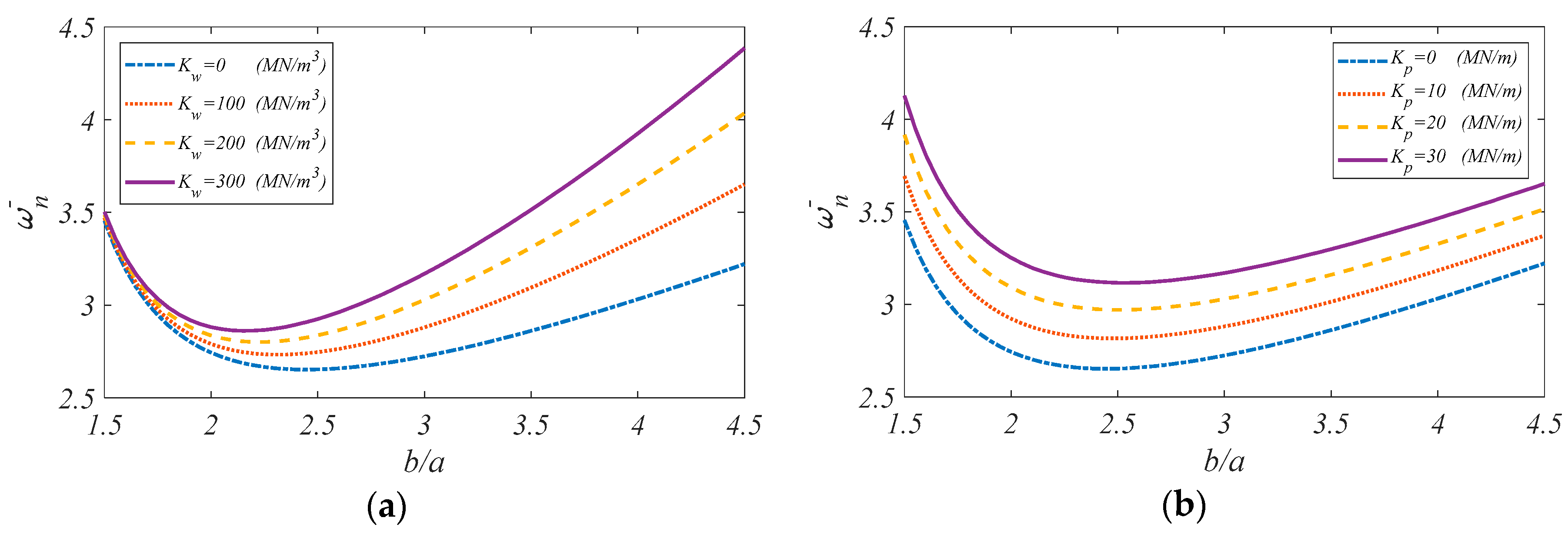
  • In the case of Pasternak-type elastic substrate, the lowest natural frequency was associated with b/a = 2.3 as the outer radius to inner radius ratio of the MHCAP.
  • The effect of the Winkler coefficient on the vibration performance of the plate was more significant when the outer radius to inner radius ratio was higher.
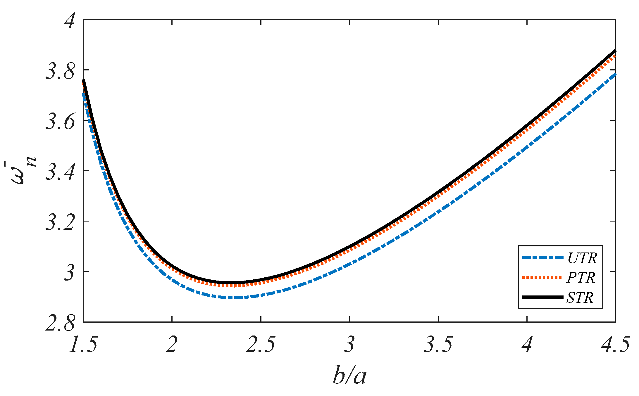
  • Applying a sinusoidal temperature rise results to a highest natural compared with associated results of other patterns of temperature rise.
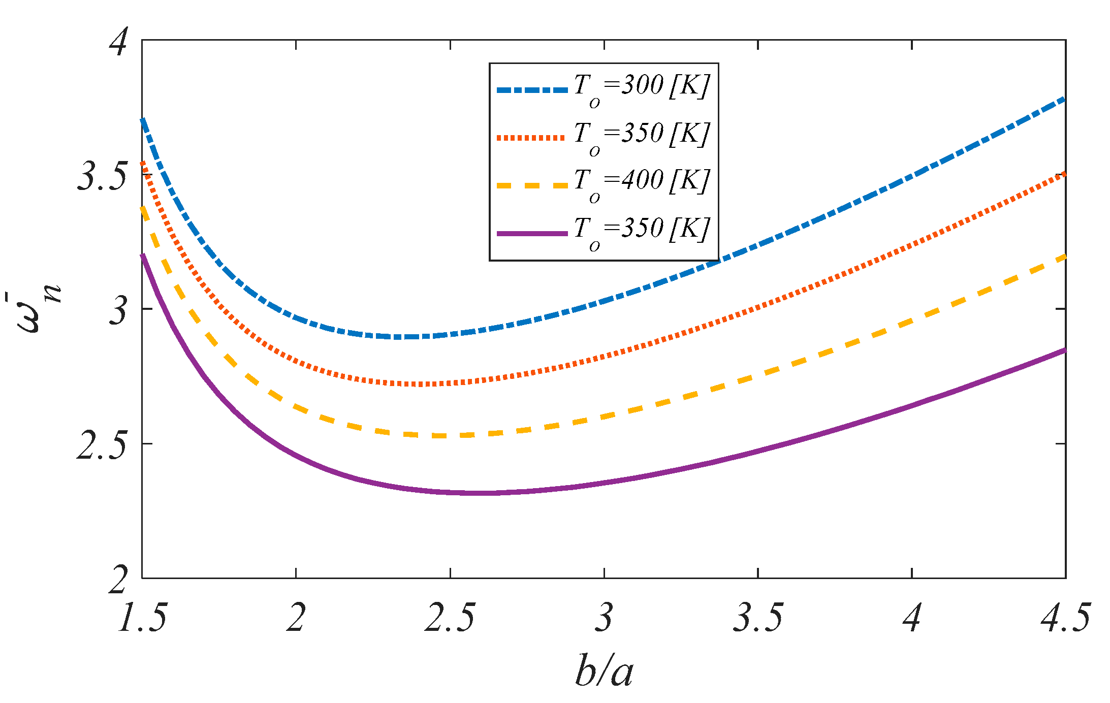
  • When the outer radius to inner radius ratio of the MHCAP was larger, the minimum frequency occurred at higher, corresponding temperature of the top surface.
  • Unlike compression load, applying higher load in extensional direction led to higher natural frequencies.
Increasing the volume fraction of carbon fiber VF improved the vibration characteristics of the plate when 0 θ 0.425 π , whereas increasing VF had a negative effect on the vibration response of the MHCAP in the case of 0.425 π θ 0.5 π .
Higher power index in the relations of STR and PTR led to a better vibration study.
The sensitivity of vibration response was higher in the case of higher nonlinear temperature gradients.

Author Contributions

Conceptualization A.R., M.S. and T.R., Formal analysis A.R. and M.S., Writing—original A.R., M.S. and T.R., Writing—review A.R., M.S. and O.N.A., Visualization A.R. and M.S. All authors have read and agreed to the published version of the manuscript.

Funding

This research received no external funding.

Conflicts of Interest

The authors declare no conflict of interest.

References

  1. Chakrapani, S.K.; Barnard, D.J.; Dayal, V. Nonlinear forced vibration of carbon fiber/epoxy prepreg composite beams: Theory and experiment. Compos. Part B Eng. 2016, 91, 513–521. [Google Scholar] [CrossRef] [Green Version]
  2. Emam, S.; Eltaher, M.A. Buckling and postbuckling of composite beams in hygrothermal environments. Compos. Struct. 2016, 152, 665–675. [Google Scholar] [CrossRef]
  3. Tornabene, F.; Fantuzzi, N.; Bacciocchi, M.; Viola, E. Effect of agglomeration on the natural frequencies of functionally graded carbon nanotube-reinforced laminated composite doubly-curved shells. Compos. Part B Eng. 2016, 89, 187–218. [Google Scholar] [CrossRef]
  4. Banić, D.; Bacciocchi, M.; Tornabene, F.; Ferreira, A.J.M. Influence of Winkler-Pasternak Foundation on the Vibrational Behavior of Plates and Shells Reinforced by Agglomerated Carbon Nanotubes. Appl. Sci. 2017, 7, 1228. [Google Scholar] [CrossRef] [Green Version]
  5. Ebrahimi, F.; Hajilak, Z.E.; Habibi, M.; Safarpour, H. Buckling and vibration characteristics of a carbon nanotube-reinforced spinning cantilever cylindrical 3D shell conveying viscous fluid flow and carrying spring-mass systems under various temperature distributions. Proc. Inst. Mech. Eng. Part C J. Mech. Eng. Sci. 2019, 233, 4590–4605. [Google Scholar] [CrossRef]
  6. Maghamikia, S.; Jam, J.E. Buckling analysis of circular and annular composite plates reinforced with carbon nanotubes using FEM. J. Mech. Sci. Technol. 2011, 25, 2805–2810. [Google Scholar] [CrossRef]
  7. Tahouneh, V.; Yas, M. Influence of equivalent continuum model based on the Eshelby-Mori-Tanaka scheme on the vibrational response of elastically supported thick continuously graded carbon nanotube-reinforced annular plates. Polym. Compos. 2014, 35, 1644–1661. [Google Scholar] [CrossRef]
  8. Tahouneh, V.; Jam, J.E. A Semi-analytical Solution for 3-D Dynamic Analysis of Thick Continuously Graded Carbon Nanotube-reinforced Annular Plates Resting on a Two-parameter Elastic Foundation. Mech. Adv. Compos. Struct. 2014, 1, 113–130. [Google Scholar] [CrossRef]
  9. Tornabene, F. Free vibration analysis of functionally graded conical, cylindrical shell and annular plate structures with a four-parameter power-law distribution. Comput. Methods Appl. Mech. Eng. 2009, 198, 2911–2935. [Google Scholar] [CrossRef]
  10. Safarpour, H.; Esmailpoor, H.Z.; Habibi, M. A size-dependent exact theory for thermal buckling, free and forced vibration analysis of temperature dependent FG multilayer GPLRC composite nanostructures restring on elastic foundation. Int. J. Mech. Mater Des. 2018. [Google Scholar] [CrossRef]
  11. Ebrahimi-Mamaghani, A.; Mirtalebi, S.H.; Ahmadian, M.-T. Magneto-mechanical stability of axially functionally graded supported nanotubes. Mater Res. Express 2020, 6, 1250. [Google Scholar] [CrossRef]
  12. Esfahani, S.; Khadem, S.E.; Mamaghani, A.E. Nonlinear vibration analysis of an electrostatic functionally graded nano-resonator with surface effects based on nonlocal strain gradient theory. Int. J. Mech. Sci. 2019, 151, 508–522. [Google Scholar] [CrossRef]
  13. Mirtalebi, S.H.; Ebrahimi-Mamaghani, A.; Ahmadian, M.T. Vibration Control and Manufacturing of Intelligibly Designed Axially Functionally Graded Cantilevered Macro/Micro-tubes. IFAC-PapersOnLine 2019, 52, 382–387. [Google Scholar] [CrossRef]
  14. Ansari, R.; Torabi, J.; Shojaei, M.F. Buckling and vibration analysis of embedded functionally graded carbon nanotube-reinforced composite annular sector plates under thermal loading. Compos. Part B Eng. 2017, 109, 197–213. [Google Scholar] [CrossRef]
  15. Keleshteri, M.M.; Asadi, H.; Wang, Q. Postbuckling analysis of smart FG-CNTRC annular sector plates with surface-bonded piezoelectric layers using generalized differential quadrature method. Comput. Methods Appl. Mech. Eng. 2017, 325, 689–710. [Google Scholar] [CrossRef]
  16. Keleshteri, M.M.; Asadi, H.; Aghdam, M.M. Geometrical nonlinear free vibration responses of FG-CNT reinforced composite annular sector plates integrated with piezoelectric layers. Compos. Struct. 2017, 171, 100–112. [Google Scholar] [CrossRef]
  17. Keleshteri, M.M.; Asadi, H.; Wang, Q. Large amplitude vibration of FG-CNT reinforced composite annular plates with integrated piezoelectric layers on elastic foundation. Thin-Walled Struct. 2017, 120, 203–214. [Google Scholar] [CrossRef]
  18. Torabi, J.; Ansari, R. Nonlinear free vibration analysis of thermally induced FG-CNTRC annular plates: Asymmetric versus axisymmetric study. Comput. Methods Appl. Mech. Eng. 2017, 324, 327–347. [Google Scholar] [CrossRef]
  19. Pang, F.; Li, H.; Du, Y.; Shan, Y.; Ji, F. Free Vibration of Functionally Graded Carbon Nanotube Reinforced Composite Annular Sector Plate With General Boundary Supports. Curved Layer. Struct. 2018, 5, 49–67. [Google Scholar] [CrossRef]
  20. Ansari, R.; Torabi, J.; Hassani, R. In-plane and shear buckling analysis of FG-CNTRC annular sector plates based on the third-order shear deformation theory using a numerical approach. Comput. Math. Appl. 2018, 75, 486–502. [Google Scholar] [CrossRef]
  21. Gholami, R.; Ansari, R. Geometrically nonlinear resonance of higher-order shear deformable functionally graded carbon-nanotube-reinforced composite annular sector plates excited by harmonic transverse loading. Eur. Phys. J. Plus 2018, 133, 56. [Google Scholar] [CrossRef]
  22. Mercan, K.; Baltacıoglu, A.K.; Civalek, Ö. Free vibration of laminated and FGM/CNT composites annular thick plates with shear deformation by discrete singular convolution method. Compos. Struct. 2018, 186, 139–153. [Google Scholar] [CrossRef]
  23. Ansari, R.; Torabi, J.; Faghih Shojaei, M. Free vibration analysis of embedded functionally graded carbon nanotube-reinforced composite conical/cylindrical shells and annular plates using a numerical approach. J. Vib. Control 2018, 24, 1123–1144. [Google Scholar] [CrossRef]
  24. Ansari, R.; Torabi, J.; Hasrati, E. Axisymmetric nonlinear vibration analysis of sandwich annular plates with FG-CNTRC face sheets based on the higher-order shear deformation plate theory. Aerosp. Sci. Technol. 2018, 77, 306–319. [Google Scholar] [CrossRef]
  25. Zhong, R.; Wang, Q.; Tang, J.; Shuai, C.; Qin, B. Vibration analysis of functionally graded carbon nanotube reinforced composites (FG-CNTRC) circular, annular and sector plates. Compos. Struct. 2018, 194, 49–67. [Google Scholar] [CrossRef]
  26. Civalek, Ö.; Baltacıoğlu, A.K. Vibration of carbon nanotube reinforced composite (CNTRC) annular sector plates by discrete singular convolution method. Compos. Struct. 2018, 203, 458–465. [Google Scholar] [CrossRef]
  27. Safarpour, M.; Rahimi, A.R.; Alibeigloo, A. Static and free vibration analysis of graphene platelets reinforced composite truncated conical shell, cylindrical shell, and annular plate using theory of elasticity and DQM. Mech. Based Des. Struct. Mach. 2019, 1–29. [Google Scholar] [CrossRef]
  28. Habibi, M.; Hashemabadi, D.; Safarpour, H. Vibration analysis of a high-speed rotating GPLRC nanostructure coupled with a piezoelectric actuator. Eur. Phys. J. Plus 2019, 134, 307. [Google Scholar] [CrossRef]
  29. Bisheh, H.; Alibeigloo, A.; Safarpour, M.; Rahimi, A. Three-Dimensional Static and Free Vibrational Analysis of Graphene Reinforced Composite Circular/Annular Plate using Differential Quadrature Method. Int. J. Appl. Mech. 2019, 11, 1950–1973. [Google Scholar] [CrossRef]
  30. Ebrahimi, F.; Hashemabadi, D.; Habibi, M.; Safarpour, H. Thermal buckling and forced vibration characteristics of a porous GNP reinforced nanocomposite cylindrical shell. Microsyst. Technol. 2019, 26, 461–473. [Google Scholar] [CrossRef]
  31. Safarpour, M.; Rahimi, A.; Alibeigloo, A.; Bisheh, H.; Forooghi, A. Parametric study of three-dimensional bending and frequency of FG-GPLRC porous circular and annular plates on different boundary conditions. Mech. Based Des. Struct. Mach. 2019, 1–31. [Google Scholar] [CrossRef]
  32. Moayedi, H.; Habibi, M.; Safarpour, H.; Safarpour, M.; Foong, L.K. Buckling and Frequency Responses of A Graphen Nanoplatelet Reinforced Composite Microdisk. Int. J. Appl. Mech. 2020. [Google Scholar] [CrossRef]
  33. Esmailpoor Hajilak, Z.; Pourghader, J.; Hashemabadi, D.; Sharifi Bagh, F.; Habibi, M.; Safarpour, H. Multilayer GPLRC composite cylindrical nanoshell using modified strain gradient theory. Mech. Based Des. Struct. Mach. 2019, 47, 521–545. [Google Scholar] [CrossRef]
  34. Habibi, M.; Mohammadi, A.; Safarpour, H.; Ghadiri, M. Effect of porosity on buckling and vibrational characteristics of the imperfect GPLRC composite nanoshell. Mech. Based Des. Struct. Mach. 2019, 1–30. [Google Scholar] [CrossRef]
  35. Rahimi, A.; Alibeigloo, A.; Safarpour, M. Three-dimensional static and free vibration analysis of graphene platelet–reinforced porous composite cylindrical shell. J. Vib. Control 2020. [Google Scholar] [CrossRef]
  36. Yang, B.; Kitipornchai, S.; Yang, Y.-F.; Yang, J. 3D thermo-mechanical bending solution of functionally graded graphene reinforced circular and annular plates. Appl. Math. Model. 2017, 49, 69–86. [Google Scholar] [CrossRef] [Green Version]
  37. Malekzadeh, P.; Setoodeh, A.R.; Shojaee, M. Vibration of FG-GPLs eccentric annular plates embedded in piezoelectric layers using a transformed differential quadrature method. Comput. Methods Appl. Mech. Eng. 2018, 340, 451–479. [Google Scholar] [CrossRef]
  38. Gholami, R.; Ansari, R. Asymmetric nonlinear bending analysis of polymeric composite annular plates reinforced with graphene nanoplatelets. JMC 2019, 17, 156. [Google Scholar] [CrossRef]
  39. Thostenson, E.T.; Li, W.Z.; Wang, D.Z.; Ren, Z.F.; Chou, T.W. Carbon nanotube/carbon fiber hybrid multiscale composites. J. Appl. Phys. 2002, 91, 6034–6037. [Google Scholar] [CrossRef]
  40. Song, Y.S. Multiscale fiber-reinforced composites prepared by vacuum-assisted resin transfer molding. Polym. Compos. 2007, 28, 458–461. [Google Scholar] [CrossRef]
  41. Bekyarova, E.; Thostenson, E.T.; Yu, A.; Kim, H.; Gao, J.; Tang, J.; Hahn, H.T.; Chou, T.-W.; Itkis, M.E.; Haddon, R.C. Multiscale Carbon Nanotube−Carbon Fiber Reinforcement for Advanced Epoxy Composites. Langmuir 2007, 23, 3970–3974. [Google Scholar] [CrossRef]
  42. Bekyarova, E.; Thostenson, E.T.; Yu, A.; Itkis, M.E.; Fakhrutdinov, D.; Chou, T.W.; Haddon, R.C. Functionalized Single-Walled Carbon Nanotubes for Carbon Fiber−Epoxy Composites. J. Phys. Chem. C 2007, 111, 17865–17871. [Google Scholar] [CrossRef]
  43. Jiang, S.; Li, Q.; Wang, J.; He, Z.; Zhao, Y.; Kang, M. Multiscale graphene oxide–carbon fiber reinforcements for advanced polyurethane composites. Compos. Part A Appl. Sci. Manuf. 2016, 87, 1–9. [Google Scholar] [CrossRef]
  44. Cougo, d.S.; Matheus, C.; Pezzin, S.H.; Pachekoski, W.M.; Amico, S.C. Multiscale hybrid composites with carbon-based nanofillers. In Nanocarbon and Its Composites; Woodhead Publishing: Cambridge, UK, 2019. [Google Scholar]
  45. Kim, M.; Park, Y.-B.; Okoli, O.I.; Zhang, C. Processing, characterization, and modeling of carbon nanotube-reinforced multiscale composites. Compos. Sci. Technol. 2009, 69, 335–342. [Google Scholar] [CrossRef]
  46. Inam, F.; Wong, D.W.Y.; Kuwata, M.; Peijs, T. Multiscale hybrid micro-nanocomposites based on carbon nanotubes and carbon fibers. J. Nanomater. 2010, 2010, 9. [Google Scholar] [CrossRef] [Green Version]
  47. Wang, B.-C.; Zhou, X.; Ma, K.-M. Fabrication and properties of CNTs/carbon fabric hybrid multiscale composites processed via resin transfer molding technique. Compos. Part B Eng. 2013, 46, 123–129. [Google Scholar] [CrossRef]
  48. Lee, S.-B.; Choi, O.; Lee, W.; Yi, J.-W.; Kim, B.-S.; Byun, J.-H.; Yoon, M.-K.; Fong, H.; Thostenson, E.T.; Chou, T.-W. Processing and characterization of multi-scale hybrid composites reinforced with nanoscale carbon reinforcements and carbon fibers. Compos. Part A Appl. Sci. Manuf. 2011, 42, 337–344. [Google Scholar] [CrossRef]
  49. Guo, J.; Lu, C.; An, F.; He, S. Preparation and characterization of carbon nanotubes/carbon fiber hybrid material by ultrasonically assisted electrophoretic deposition. Mater. Lett. 2012, 66, 382–384. [Google Scholar] [CrossRef]
  50. Thostenson, E.T.; Gangloff, J.J.; Li, C.; Byun, J.-H. Electrical anisotropy in multiscale nanotube/fiber hybrid composites. Appl. Phys. Lett. 2009, 95, 073111. [Google Scholar] [CrossRef]
  51. Qin, F.X.; Brosseau, C.; Peng, H.X. Microwave properties of carbon nanotube/microwire/rubber multiscale hybrid composites. Chem. Phys. Lett. 2013, 579, 40–44. [Google Scholar] [CrossRef]
  52. Pal, G.; Kumar, S. Multiscale modeling of effective electrical conductivity of short carbon fiber-carbon nanotube-polymer matrix hybrid composites. Mater. Des. 2016, 89, 129–136. [Google Scholar] [CrossRef]
  53. Sung, D.H.; Kim, M.; Park, Y.-B. Prediction of thermal conductivities of carbon-containing fiber-reinforced and multiscale hybrid composites. Compos. Part B Eng. 2018, 133, 232–239. [Google Scholar] [CrossRef]
  54. Rodriguez, A.J.; Guzman, M.E.; Lim, C.-S.; Minaie, B. Mechanical properties of carbon nanofiber/fiber-reinforced hierarchical polymer composites manufactured with multiscale-reinforcement fabrics. Carbon 2011, 49, 937–948. [Google Scholar] [CrossRef]
  55. Rahmanian, S.; Suraya, A.R.; Shazed, M.A.; Zahari, R.; Zainudin, E.S. Mechanical characterization of epoxy composite with multiscale reinforcements: Carbon nanotubes and short carbon fibers. Mater. Des. 2014, 60, 34–40. [Google Scholar] [CrossRef] [Green Version]
  56. Radue, M.S.; Odegard, G.M. Multiscale modeling of carbon fiber/carbon nanotube/epoxy hybrid composites: Comparison of epoxy matrices. Compos. Sci. Technol. 2018, 166, 20–26. [Google Scholar] [CrossRef]
  57. Li, W.; Dichiara, A.; Zha, J.; Su, Z.; Bai, J. On improvement of mechanical and thermo-mechanical properties of glass fabric/epoxy composites by incorporating CNT–Al2O3 hybrids. Compos. Sci. Technol. 2014, 103, 36–43. [Google Scholar] [CrossRef]
  58. Hadden, C.M.; Klimek-McDonald, D.R.; Pineda, E.J.; King, J.A.; Reichanadter, A.M.; Miskioglu, I.; Gowtham, S.; Odegard, G.M. Mechanical properties of graphene nanoplatelet/carbon fiber/epoxy hybrid composites: Multiscale modeling and experiments. Carbon 2015, 95, 100–112. [Google Scholar] [CrossRef] [Green Version]
  59. Aluko, O.; Gowtham, S.; Odegard, G.M. Multiscale modeling and analysis of graphene nanoplatelet/carbon fiber/epoxy hybrid composite. Compos. Part B Eng. 2017, 131, 82–90. [Google Scholar] [CrossRef]
  60. Al Mahmud, H.; Radue, M.; Chinkanjanarot, S.; Pisani, W.; Gowtham, S.; Odegard, G. Predicting the Effective Mechanical Properties of Graphene Nanoplatelet-Carbon Fiber-Epoxy Hybrid Composites Using ReaxFF: A Multiscale Modeling. Earth Space 2018, 16, 556. [Google Scholar]
  61. Al Mahmud, H.; Radue, M.S.; Chinkanjanarot, S.; Pisani, W.A.; Gowtham, S.; Odegard, G.M. Multiscale modeling of carbon fiber- graphene nanoplatelet-epoxy hybrid composites using a reactive force field. Compos. Part B Eng. 2019, 172, 628–635. [Google Scholar] [CrossRef]
  62. Zhang, X.; Yang, W.; Zhang, J.; Ge, X.; Liu, X.; Zhan, Y. Multiscale graphene/carbon fiber reinforced copper matrix hybrid composites: Microstructure and properties. Mater. Sci. Eng. A 2019, 743, 512–519. [Google Scholar] [CrossRef]
  63. Ebrahimi, F.; Habibi, S. Thermal effects on nonlinear dynamic characteristics of polymer-CNT-fiber multiscale nanocomposite structures. Struct. Eng. Mech. 2018, 67, 403–415. [Google Scholar] [CrossRef]
  64. Ebrahimi, F.; Habibi, S. Nonlinear eccentric low-velocity impact response of a polymer-carbon nanotube-fiber multiscale nanocomposite plate resting on elastic foundations in hygrothermal environments. Mech. Adv. Mater. Struct. 2018, 25, 425–438. [Google Scholar] [CrossRef]
  65. Ahmadi, M.; Ansari, R.; Rouhi, H. Studying buckling of composite rods made of hybrid carbon fiber/carbon nanotube reinforced polyimide using multiscale FEM. Sci. Iran. 2018, 27, 252–261. [Google Scholar] [CrossRef] [Green Version]
  66. Ahmadi, M.; Ansari, R.; Rouhi, H. Free and forced vibration analysis of rectangular/circular/annular plates made of carbon fiber-carbon nanotube-polymer hybrid composites. Sci. Eng. Compos. Mater. 2019, 26, 70–76. [Google Scholar] [CrossRef] [Green Version]
  67. Ebrahimi, F.; Dabbagh, A. On thermo-mechanical vibration analysis of multi-scale hybrid composite beams. J. Vib. Control 2019, 25, 933–945. [Google Scholar] [CrossRef]
  68. Karimiasl, M.; Ebrahimi, F.; Vinyas, M. Nonlinear vibration analysis of multiscale doubly curved piezoelectric composite shell in hygrothermal environment. J. Intell. Mater. Syst. Struct. 2019, 30, 1594–1609. [Google Scholar] [CrossRef]
  69. Karimiasl, M.; Ebrahimi, F.; Mahesh, V. Nonlinear free and forced vibration analysis of multiscale composite doubly curved shell embedded in shape-memory alloy fiber under hygrothermal environment. J. Vib. Control 2019, 25, 1945–1957. [Google Scholar] [CrossRef]
  70. Karimiasl, M.; Ebrahimi, F.; Akgöz, B. Buckling and post-buckling responses of smart doubly curved composite shallow shells embedded in SMA fiber under hygro-thermal loading. Compos. Struct. 2019, 223, 110988. [Google Scholar] [CrossRef]
  71. Ebrahimi, F.; Dabbagh, A. Vibration analysis of multi-scale hybrid nanocomposite plates based on a Halpin-Tsai homogenization model. Compos. Part B Eng. 2019, 173, 106955. [Google Scholar] [CrossRef]
  72. Ebrahimi, F.; Dabbagh, A. An analytical solution for static stability of multi-scale hybrid nanocomposite plates. Eng. Comput. 2019, 1–15. [Google Scholar] [CrossRef]
  73. Tornabene, F.; Bacciocchi, M.; Fantuzzi, N.; Reddy, J.N. Multiscale approach for three-phase CNT/polymer/fiber laminated nanocomposite structures. Polym. Compos. 2019, 40, 102–126. [Google Scholar] [CrossRef]
  74. Na, K.-S.; Kim, J.-H. Three-dimensional thermal buckling analysis of functionally graded materials. Compos. Part B Eng. 2004, 35, 429–437. [Google Scholar] [CrossRef]
  75. Tornabene, F.; Fantuzzi, N.; Ubertini, F.; Viola, E. Strong Formulation Finite Element Method Based on Differential Quadrature: A Survey. Appl. Mech. Rev. 2015, 67, 20801. [Google Scholar] [CrossRef]
  76. Shahgholian-Ghahfarokhi, D.; Safarpour, M.; Rahimi, A. Torsional buckling analyses of functionally graded porous nanocomposite cylindrical shells reinforced with graphene platelets (GPLs). Mech. Based Des. Struct. Mach. 2019, 10, 1–22. [Google Scholar] [CrossRef]
  77. Guo, H.; Zhuang, X.; Rabczuk, T. A Deep Collocation Method for the Bending Analysis of Kirchhoff Plate. CMC-Comput. Mater. Contin. 2019, 59, 433–456. [Google Scholar] [CrossRef]
  78. Bellman, R.; Casti, J. Differential quadrature and long-term integration. J. Math. Anal. Appl. 1971, 34, 235–238. [Google Scholar] [CrossRef] [Green Version]
  79. Bellman, R.; Kashef, B.G.; Casti, J. Differential quadrature: A technique for the rapid solution of nonlinear partial differential equations. J. Comput. Phys. 1972, 10, 40–52. [Google Scholar] [CrossRef]
  80. Shu, C. Differential Quadrature and Its Application in Engineering; Springer Science & Business Media: Berlin, Germany, 2012. [Google Scholar]
  81. Shu, C.; Richards, B.E. Application of generalized differential quadrature to solve two-dimensional incompressible Navier-Stokes equations. Int. J. Numer. Methods Fluids 1992, 15, 791–798. [Google Scholar] [CrossRef]
  82. Wang, Y.; Zeng, R.; Safarpour, M. Vibration analysis of FG-GPLRC annular plate in a thermal environment. Mech. Based Des. Struct. Mach. 2020, 1–19. [Google Scholar] [CrossRef]
  83. Han, J.-B.; Liew, K. Axisymmetric free vibration of thick annular plates. Int. J. Mech. Sci. 1999, 41, 1089–1109. [Google Scholar] [CrossRef]
Figure 1. Schematic view of the multiscale hybrid annular plate, related parameters, and coordination.
Applsci 10 01412 g001
Figure 2. Overview of multiscale hybrid composite.
Applsci 10 01412 g002
Figure 3. Distribution patterns of carbon nanotube (CNT) through the thickness of the multiscale hybrid annular plate. (a) UD; (b) FG-X; (c) FG-A; (d) FG-V.
Applsci 10 01412 g003
Figure 4. Through-the-thickness variation of mechanical properties ( θ = π / 4 ,   W C N T = 0.02 ,   V F = 0.2 ) .
Applsci 10 01412 g004
Figure 5. Convergence of nondimensional natural frequency of MHCAP with b/a = 4, h/b = 0.1, Ti = 273 [K], To = 300 [K], weight fraction of CNT (WCNT = 0.02), volume fraction of carbon fiber (VF = 0.2), θ = π/4, UTR, β = 1, FG-A, Kw = 0 [M N/m3] and Kp = 0 [M N/m] for various boundary conditions. (a) Simply-Simply; (b) Clamp-Clamp; (c) Clamp-Simply.
Applsci 10 01412 g005
Figure 6. The effect of Winkler–Pasternak coefficient on the nondimensional natural frequency of MHCAP with clamp-clamp boundary conditions for different outer radius to inner radius ratios and h/b = 0.1, UTR, Ti = 273 [K], To = 300 [K], θ = π/4, WCNT = 0.02, VF = 0.2, FG-A, β = 1, (a) Kp = 0, and (b) Kw = 0. (a) Winkler coefficient; (b) Pasternak coefficient.
Applsci 10 01412 g006
Figure 7. The effect of temperature rising pattern on the nondimensional natural frequency of MHCAP with clamp-clamp boundary conditions for different outer radius to inner radius ratios and h/b = 0.1, Ti = 273 [K], To = 300 [K], θ = π/4, WCNT = 0.02, VF = 0.2, β = 1, FG-A, Kp = 10 [MN/m], and Kw = 100 [MN/m3].
Applsci 10 01412 g007
Figure 8. The effect of applied temperature of the top surface on the nondimensional natural frequency of MHCAP with clamp-clamp boundary conditions for different outer radius ratios of inner radius and h/b = 0.1, Ti = 273 [K], UTR, θ = π/4, WCNT = 0.02, VF = 0.2, FG-A, β = 1, Kp = 10 [MN/m], and Kw = 100 [MN/m3].
Applsci 10 01412 g008
Figure 9. The effect of various volume fractions of carbon fiber on the nondimensional natural frequency of MHCAP with clamp-clamp boundary conditions for different orientation angle of carbon fibers and b/a = 4, h/b = 0.1, sinusoidal temperature rise (STR), Ti = 273 [K], To = 300 [K], WCNT = 0.02, FG-A, β = 1, Kp = 10 [MN/m], and Kw = 100 [MN/m3].
Applsci 10 01412 g009
Figure 10. The effect of various weight fraction of CNTs on the nondimensional natural frequency of MHCAP with clamp-clamp boundary conditions for different orientation angles of carbon fibers and b/a = 4, h/b = 0.1, STR, Ti = 273 [K], To = 300 [K], VF = 0.2, FG-A, β = 1, Kp = 10 [MN/m], and Kw = 100 [MN/m3].
Applsci 10 01412 g010
Figure 11. The effect of different outer radius to inner radius ratios on the nondimensional natural frequency of MHCAP with clamp-clamp boundary conditions for different orientation angles of carbon fibers and h/b = 0.1, STR, Ti = 273 [K], To = 273 [K], WCNT = 0.02, VF = 0.2, FG-A, β = 1, Kp = 10 [MN/m], and Kw = 100 [MN/m3]. (a) without elastic medium; (b) rested on Winkler medium; (c) rested on Winkler-Pasternak medium.
Applsci 10 01412 g011
Figure 12. The effect of applied temperature of the top surface on the nondimensional natural frequency of MHCAP with clamp-clamp boundary conditions for different temperature power β and h/b = 0.1, b = 4 × a, Ti = 273 [K], WCNT = 0.02, VF = 0.2, FG-A, Kp = 10 [MN/m], and Kw = 100 [MN/m3]. (a) STR; (b) PTR.
Applsci 10 01412 g012
Figure 13. Sensitivity of the natural frequency of MHCAP with clamp-clamp boundary conditions to nonlinear temperature gradient for different values of β parameter in STR and power form temperature rise (PTR) and h/b = 0.1, θ = π/4, WCNT = 0.02, VF = 0.2, FG-A, Kp = 10 [MN/m], and Kw = 100 [MN/m3].
Applsci 10 01412 g013
Table 1. Material properties of the multiscale hybrid nanocomposite annular plate [64].
Carbon fiber   E 11 F [ Gpa ] 233 . 05   E 22 F [ Gpa ] 23 . 1   G 12 F [ Gpa ]   8 . 96   ρ F [ kg / m 3 ]   1750 ν F   0 . 2   α 11 F [ × 10 6 / k ]   0 . 54   α 22 F [ × 10 6 / k ]   10 . 08
Epoxy Matrix   E m [ Gpa ]   3 . 51   ν m 0 . 34   ρ m [ kg / m 3 ]   1200   α m [ × 10 6 / k ]   45
Carbon nanotube   E 11 F [ Tpa ] 5 . 6466 E 22 C N T = E 33 C N T [ Tpa ]   7 . 0800 G 12 C N T = G 13 C N T [ Tpa ]   1 . 9445 ν 12 C N T   0 . 175   ρ CNT [ kg / m 3 ]   1350   α C N T [ × 10 6 / k ]   3 . 4584   l CNT [ μ m ]   25   d CNT   [ nm ]   1 . 4   t CNT   [ nm ]   0 . 34
Table 2. Comparison of nondimensional natural frequency of the annular plate for different axisymmetric vibration mode number, inner radius to outer radius ratio, and thickness to outer radius ratio for simply-simply boundary condition.
a b h b Axisymmetric Vibration Mode Number
1234
0.1Ref. [83]0.00114.48551.781112.99198.44
Present0.00113.62450.302111.86198.61
Ref. [83]0.05014.32450.409107.25182.55
Present0.05013.52849.109106.09182.08
Ref. [83]0.10013.87446.94794.670151.91
Present0.10013.25446.06193.794151.36
Ref. [83]0.15013.21842.63081.519124.92
Present0.15012.83842.18281.036124.24
Ref. [83]0.20012.45038.33770.224104.20
Present0.20012.32638.24370.075104.04
0.2Ref. [83]0.00116.78063.370140.60248.62
Present0.00116.65263.003140.90250.68
Ref. [83]0.05016.61861.512132.21224.50
Present0.05016.51261.164131.99225.32
Ref. [83]0.10016.16456.912114.70182.50
Present0.10016.11856.621114.14181.93
Ref. [83]0.15015.49151.31797.337147.50
Present0.15015.52951.10896.780146.33
Ref. [83]0.20014.68845.86682.963121.66
Present0.20014.81945.75182.567121.21
Table 3. Comparison of nondimensional natural frequency of the annular plate for different axisymmetric vibration mode number, inner radius to outer radius ratio, and thickness to outer radius ratio for clamp-simply boundary condition.
a b h b Axisymmetric Vibration Mode Number
1234
0.1Ref. [83]0.00122.70165.538132.89224.41
Present0.00120.85263.734131.50223.86
Ref. [83]0.05022.29463.052123.85201.54
Present0.05020.49061.122121.73198.97
Ref. [83]0.10021.20056.912105.46161.99
Present0.10019.51254.993102.79158.00
Ref. [83]0.15019.70349.87987.884129.69
Present0.15018.16648.11985.479126.15
Ref. [83]0.20018.07343.43173.899106.37
Present0.20016.69541.97272.128104.17
0.2Ref. [83]0.00126.73780.722165.63281.34
Present0.00125.77279.931165.66282.52
Ref. [83]0.05026.24277.053152.26247.24
Present0.05025.22775.901150.67244.70
Ref. [83]0.10024.91668.635126.72193.10
Present0.10023.78566.912123.76188.24
Ref. [83]0.15023.11359.407103.85151.97
Present0.15021.86957.463100.99147.52
Ref. [83]0.20021.16251.24786.427123.40
Present0.20019.85349.45684.276120.89
Table 4. Comparison of nondimensional natural frequency of the annular plate for different axisymmetric vibration mode number, inner radius to outer radius ratio, and thickness to outer radius ratio for clamp-clamp boundary condition.
a b h b Axisymmetric Vibration Mode Number
1234
0.1Ref. [83]0.00127.28075.364148.21245.47
Present0.00128.51477.363151.05249.05
Ref. [83]0.05026.53471.228135.24215.08
Present0.05027.67972.766136.36214.46
Ref. [83]0.10024.62962.140111.12167.16
Present0.10025.55862.834110.39163.41
Ref. [83]0.15022.23052.76290.286131.35
Present0.15022.90952.83588.962127.51
Ref. [83]0.20019.84344.91374.860106.81
Present0.20020.29444.68373.628103.75
0.2Ref. [83]0.00134.60995.738188.14311.40
Present0.00135.71297.395190.61314.62
Ref. [83]0.05033.53389.550168.60265.78
Present0.05034.42690.285168.15262.39
Ref. [83]0.10030.84176.560134.71200.02
Present0.10031.27475.895131.87193.37
Ref. [83]0.15027.54563.827107.32154.20
Present0.15027.53462.466104.32152.53
Ref. [83]0.20024.34853.57487.870123.93
Present0.20024.02252.12285.531121.89
Table 5. Effect of CNT pattern on the nondimensional natural frequency of the simply-simply multiscale hybrid composite annular plate (MHCAP) with outer radius to inner radius ratio (b/a = 4), thickness ratio (h/b = 0.2), temperature at bottom surface (Ti = 273 [K]), temperature at top surface (To = 300 [K]), orientation angle of fibers (θ = π/4), Winkler coefficient (Kw = 0 [N/m3]), Pasternak coefficient (Kp = 0 [N/m]), axial load (P = 0 [N]), uniform temperature rise (UTR), and β = 1 for different weight fractions of CNT and volume fractions of carbon fiber.
VFCNT Distribution W C N T
0.020.040.060.080.1
0.2FG-X2.70592.99763.22553.41953.5921
FG-V2.78693.05963.24983.40183.5325
FG-A2.82173.10383.30063.45893.5958
FG-UD2.80893.08893.28543.44393.5812
0.3FG-X2.95993.26043.48083.65963.8132
FG-V3.08063.38173.57833.72653.8479
FG-A3.12033.42913.62943.78093.9058
FG-UD3.10703.41563.61703.76953.8950
0.4FG-X3.17113.47223.68363.84863.9859
FG-V3.31393.62783.82453.96704.0796
FG-A3.35633.67663.87534.01914.1332
FG-UD3.34373.66623.86754.01324.1283

