Article

Discrete Fourier Transform-Based Block Faster-Than- Nyquist Transmission for 5G Wireless Communications

1
Shanghai Advanced Research Institute, Chinese Academy of Sciences, Shanghai 201210, China
2
University of Chinese Academy of Sciences, Beijing 100049, China
*
Author to whom correspondence should be addressed.
Appl. Sci. 2020, 10(4), 1313; https://doi.org/10.3390/app10041313
Submission received: 16 January 2020 / Revised: 10 February 2020 / Accepted: 11 February 2020 / Published: 14 February 2020
(This article belongs to the Section Electrical, Electronics and Communications Engineering)

Abstract

:
Faster-than-Nyquist (FTN) signaling is regarded as a potential candidate for improving data rate and spectral efficiency of 5G new radio (NR). However, complex detectors have to be utilized to eliminate the inter symbol interference (ISI) introduced by time-domain packing and the inter carrier interference (ICI) introduced by frequency-domain packing. Thus, the exploration of low complexity transceiver schemes and detectors is of great importance. In this paper, we consider a discrete Fourier transform (DFT) block transmission for multi-carrier FTN signaling, i.e., DBT-MC-FTN. With the aid of DFTs/IDFTs and frequency domain windowing, time- and frequency domain packing can be implemented flexibly and efficiently. At the receiver, the inherent ISI and ICI can be canceled via a soft successive interference cancellation (SIC) detector. The effectiveness of the detector is verified by the simulation over the additive white Gaussian noise channel and the fading channel. Furthermore, based on the characteristics of the efficient architecture of DFT-MC-FTN, two pilot-aided channel estimation schemes, i.e., time-division-multiplexing DBT-MC-FTN symbol-level pilot, and frequency-division-multiplexing subcarrier-level pilot within the DBT-MC-FTN symbol, respectively, are also derived. Numerical results show that the proposed channel estimation schemes can achieve high channel estimation accuracy.

1. Introduction

In order to meet the unprecedented requirement for high-data-rate transmission and to achieve higher spectral efficiency, non-orthogonal transmission techniques in time- and/or frequency domain have attracted worldwide attention in the academia and the industry, especially during the standardization process of the 5G new radio (NR) [1]. Faster-than-Nyquist (FTN) was originally proposed by Mazo in 1975 [2]. As a kind of non-orthogonal transmission technology, FTN has broken the traditional Nyquist criterion and the data rate can be increased by 25% at the expanse of introducing ineluctable inter-symbol interference (ISI) artificially. Therefore, FTN transmission technology has attracted wide attention in recent years as a potential time-domain solution to effectively improve spectral efficiency. Furthermore, FTN signaling has also been studied in a frequency domain [3,4,5,6] and then extended to both time and frequency domains [7,8,9,10]. The principle of frequency domain FTN signaling is that the modulated symbols are multiplexed onto the non-orthogonal sub-carriers which are placed at closer spacing compared to an OFDM system, i.e., bandwidth compression, thus less bandwidth resource can be occupied. At the receiver, complex detectors such as the maximum likelihood (ML) detector should be adopted to cancel the artificially introduced inter-carrier interference (ICI), however, with the complexity growing exponentially with the system size, e.g., the number of subcarriers or the constellation size.
To tackle the high transceiver complexity problem, a number of efficient transceiver schemes have been developed for the FTN signaling transmission [11,12,13,14]. For example, Ref. [13] proposes a circulated block transmission scheme, i.e., CB-FTN, in which circular convolution instead of the linear convolution is utilized to conduct the pulse shaping. Thus, low-complexity frequency domain equalization can be employed at the receiver to compensate for the channel impairment and the inherent ISI. Ref. [14] proposes the discrete Fourier transform (DFT) based block transmission for faster-than-Nyquist signaling (DBT-FTN) scheme where the implementation complexity of DBT-FTN system can be reduced significantly by DFT based signal generation and frequency-domain equalization (FDE) in the transmitter and receiver, respectively. Ref. [8] develops a new multicarrier FTN signaling transceiver with an FTN mapper and a linear minimum mean square error (LMMSE) equalizer. There are also works on other low complexity detectors like nonlinear detection algorithms based on maximum a posteriori (MAP) [15], Turbo-based frequency domain equalization [16,17] and improved linear equalization algorithms [18]. To the best of our knowledge, these approaches, however, are mainly designed for the FTN system with one-dimensional compression and perform efficiently only for the additive white Gaussian noise (AWGN) channel scenario. In terms of fading channels, the inherent ISI and/or ICI of the FTN signaling combined with the ISI induced by the fading channel will even challenge the accuracy of the channel estimation. Under such circumstances, the efficient single-tap frequency domain channel estimation schemes for the OFDM system cannot be utilized directly due to the existence of the mixed interference [19,20,21]. Thus, the exploration of the efficient channel estimation schemes for FTN signaling is of great importance.
The state-of-the art studies on the channel estimation in the FTN system can be divided into two categories, i.e., pilot-aided channel estimation schemes and the ones without the pilot. To save the pilot overhead, the channel estimation schemes without an assisted pilot are proposed by using differential modulation and correlation coefficient matrix to carry on non-coherent detection [22]. However, it is different from the current mainstream modulation scheme and cannot be compatible with the existing multi-carrier FTN transmission schemes. In terms of the pilot-aided channel estimation, the pilot-aided channel estimation schemes consist of two parts: (1) Channel estimation using orthogonal pilots: As the subcarrier interval of the FTN signal is the same as that of the OFDM system, the compatible channel estimation scheme can be adopted. However, compared with the FTN signal, the time duration of an orthogonal pilot symbol is longer than that of the FTN symbols due to the lower data rate in each subcarrier, resulting in a slight decrease in the spectral efficiency [23,24,25,26,27]. Furthermore, the pilot symbols and the data symbols are time division multiplexing and the longer symbol period will lead to the inapplicability of rapidly time-varying multipath fading channels. (2) Channel estimation using DBT-MC-FTN pilots: When the DBT-MC-FTN symbol is used as the pilot for channel estimation, the period of the symbol is the same as that of an orthogonal symbol while the subcarrier interval is compressed. As a result, there is no effect on the spectral efficiency, but the self-introduced ISI and ICI will affect the accuracy of channel estimation [28,29,30,31,32]. Moreover, to apply the above channel estimation and equalization scheme, some frame structures based on FTN transmission have been proposed in [9,10,15,33,34].
In this paper, a low complexity two-dimensional compression scheme called DFT based block transmission for multicarrier faster-Than-Nyquist (DBT-MC-FTN) signaling is proposed. The key idea of the proposed DBT-MC-FTN can be depicted as follows. By resorting to the circular convolution and DFT operation, an efficient transceiver architecture is derived. The proposed DBT-MC-FTN transmitter can be viewed as the concatenation of several smaller size DFTs, frequency domain window, and a larger size IDFT, and the receiver is the corresponding reverse process. As a result, flexible time- and frequency domain compressions can be achieved in a unified manner. One difference between our scheme and the one proposed in [8] is that frequency domain compression cannot be achieved for the latter, thus full use may not be made of the scarce spectral resource. To combat the multipath effect in the fading channel, a cyclic prefix (CP) is added to the DBT-MC-FTN symbol so that channel induced ISI can be eliminated through frequency domain equalization. Moreover, since the artificially introduced ISI and ICI in the DBT-MC-FTN system are known to us when the compression factor is determined, the ISI and ICI can be computed offline and canceled via the soft successive interference cancellation (SIC) detector at the receiver with an acceptable complexity.
To sum up, the novel contributions of this paper are as follows:
  • We first propose a DFT based block transmission for multicarrier FTN signaling scheme, i.e., DBT-MC-FTN, where the two-dimensional compression in both time-domain and frequency-domain can be realized efficiently by adjusting the operation parameters.
  • CP-based channel frequency domain equalization and soft SIC detector are deployed respectively to eliminate the ISI and ICI introduced by the channel and the two-dimensional packing in the DBT-MC-FTN signaling. The effectiveness of the proposed detector is verified by the simulations.
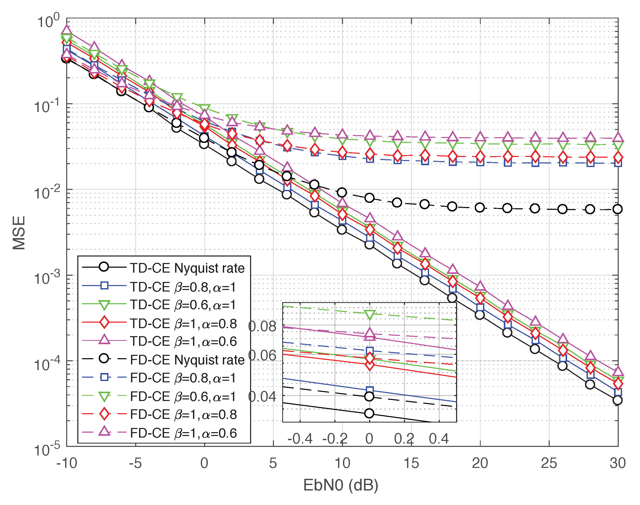
  • Based on the special structure of the proposed DBT-MC-FTN scheme, two pilot transmission schemes for channel estimation have been proposed. The two schemes are time-division multiplexing (TDM) non-orthogonal pilots and multiplexing orthogonal pilots in the same time-frequency resource, respectively. We demonstrate that time-domain estimation using non-orthogonal pilots performs better while other schemes have error floors when the simple least square (LS) algorithm is implemented.
The remainder of this paper is organized as follows. In Section 2, we present the system model of the proposed DBT-MC-FTN system and propose the corresponding receiver that takes consideration of the influence of a multipath fading channel. Furthermore, a soft SIC equalizer has also been provided to estimate the self-introduced interference. In Section 3, the methodologies of implementing the two pilot transmission and channel estimation schemes have been introduced, respectively. Section 4 provides the channel estimation (CE) and bit error rate (BER) performance results of the proposed scheme. Finally, Section 5 includes the conclusions and future work.
Notation: Matrices, vectors, and scalar quantities are denoted by boldface uppercase, boldface lowercase and normal letters, respectively. Appendix A presents notations used in this paper.

2. System Model of DBT-MC-FTN

Based on our previous work in [11,12], FTN signaling is further applied in both time and frequency domains. In this work, a unique DFT-based block transmission for multi-carrier FTN signaling, i.e., DBT-MC-FTN has been proposed. Figure 1 depicts the schematic block diagram of the DBT-MC-FTN transceiver.

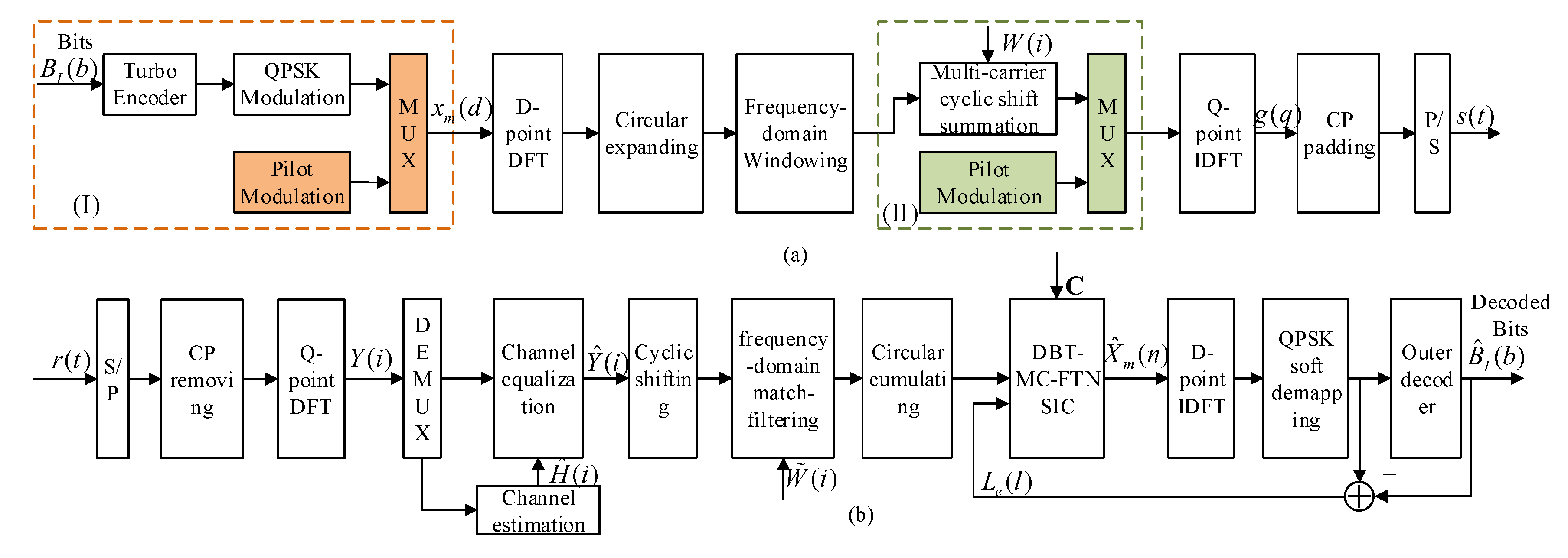
2.1. DBT-MC-FTN Transmitter

DBT-MC-FTN is essentially a multi-carrier scheme. Denote x m ( d ) as the dth complex QPSK symbol modulated on the mth subcarrier, then the continuous-time transmitted signal of DBT-MC-FTN signaling can be expressed as
g ( t ) = d = 0 D 1 m = 0 M 1 x m ( d ) w t d β T s e j 2 π m α t T s ,
where w ( t ) is the continuous-time unit energy pulse with the Nyquist symbol interval T s , M, and D are, respectively, the numbers of occupied subcarriers and the symbols transmitted on each subcarrier. α ( α 1 ) and β ( β 1 ) denote the frequency packing factor (FPF) and the time packing factor (TPF), respectively. We set v = α · β as the joint time-frequency packing factor. For α = 1 and β = 1 , an orthogonal system is obtained, while for α < 1 or β < 1 , frequency-domain or time-domain packing occurs between the subcarriers or symbols. Figure 2 illustrates the time-frequency grid comparison between the multicarrier FTN system and the orthogonal systems, from which the relationship between the desired signal and introduced ISI/ICI can be recognized clearly. As a result, the improvement of spectral efficiency is obvious.
By sampling the signal in Equation (1) at the sampling period of T s / N s , the discrete signal can be written as
g ( q ) = 1 N s d = 0 D 1 m = 0 M 1 x m ( d ) w q d N f Q e j 2 π m α q N s ,
where N f = β N s , 0 q Q 1 , 1 N s is a normalization scaling factor. w ( n ) is a N s -orthogonal pulse with the length of L, where n = 0 L 1 w ( n ) w * ( n d N s ) = 0 when d 0 . The operator of ( ( · ) ) Q represents the Modulo-Q operation where Q = D × N f and Q > L . By applying Q-point IDFT operation to both sides of Equation (2), the frequency-domain expression of DBT-MC-FTN signal can be derived as
G ( i ) = D m = 0 M 1 X m ( i m α β D ) W ( i m α β D ) ,
where 0 i Q 1 , X m ( i ) is the D-point DFT of x m ( d ) and W ( i ) is the Q-point DFT of w ( n ) . Equation (3) can be interpreted as follows. The data symbols transmitted on each subcarrier are first transformed into the frequency domain with D-point DFT, and then extended circularly to Q points. Each Q-point output signal is multiplied by a frequency-domain window whose length is variable according to the TPF β . After the summation of the M Q-point signals circularly with the shift interval m α β D , Q-point IDFT, and CP padding, finally, DBT-MC-FTN signaling is generated, as shown in Figure 1a. Note that the two-dimensional time-frequency packing can be realized in a unified manner via the overall packing factor v. The time-domain packing is implemented by adjusting the window length, and the frequency-domain packing is realized by multi-carrier cyclic shift summation with the FPF α . Change the window length and the multi-carrier summation cyclic shift interval at the same time, time-frequency packing can be simultaneously realized. It is worth pointing out that the proposed DBT-MC-FTN scheme can be viewed as the fast-than-Nyquist extension of SC-OFDM (i.e., DFT-S-OFDM). In the case of M = 1 , α = β = 1 , and the window is a rectangular pulse, obviously, it becomes the traditional SC-OFDM. If the rectangular pulse is used, the proposed scheme without time-frequency packing will transformed into an N × SC-OFDM scheme. To take the general cases into consideration, the coefficients of all the M D point DFTs will be packed, sequentially mapped, and superimposed on each subcarrier of the Q-point IDFT within the DBT-MC-FTN symbol; hence, this is the faster-than-Nyquist extension of SC-OFDM.
The DBT-MC-FTN signaling can be also expressed in matrix form. Let V = { v 0 , v 1 , , v M 1 } be the output signal matrix on M subcarriers before Q-point IDFT operation, the symbol vector on the mth carrier can be given as
v m = D S m W T Q , D F D x m ,
where x m = [ x m ( 0 ) , x m ( 1 ) , , x m ( D 1 ) ] T is the data signal vector on the mth subcarrier, F D and F D H are the D × D Fourier/Inverse Fourier transform matrix, T Q , D = [ I D , I D , , I D ] T indicates Q × D cyclic extension matrix with D-dimensional identity matrix I D . W = d i a g { W ( 0 ) W ( 1 ) W ( Q 1 ) } is defined as the frequency-domain window matrix and S m is the mth cyclic shift matrix. As a result, after the multi-carrier summation in Equation (3) and Q-point IDFT, the transmitted DBT-MC-FTN signal vector in Equation (2) can be shown as
g = F Q H Ω Λ X = Φ X ,
where Ω = [ S 0 S 1 S M 1 ] , Λ = diag ( W T Q , D F D ) , X = [ x 0 x 1 x M 1 ] T and Φ is the equivalent matrix of the transmitter.

2.2. DBT-MC-FTN Receiver

Assume that, in a DBT-MC-FTN transmission block, the time domain impulse response of a multipath fading channel is approximately constant. Then, at the receiver, the channel impulse response (CIR) vector can be denoted as h = [ h 1 , h 2 , h Q ] T . After CP removing, the received signal can be expressed as
y = g h + z ,
where y = [ y 1 , y 2 , , y Q ] T is the receiver signal vector, z = [ z 1 , z 2 , , z Q ] T denotes the additive white Gaussian noise (AWGN) with zero mean and the variance of σ 2 , ⊗ stands for the circular convolution.
Because of the periodicity of the transmitted symbol, Equation (6) can be rewritten in the form of a circulant matrix as follows:
y = H c Φ X + z = Θ h + z ,
where H c is a circulant matrix constructed by h = [ h 1 , h 2 , h Q ] T . Ψ = Φ 1 Φ Q Φ 2 Φ 2 Φ 1 Φ Q Φ Q Φ 2 Φ 1 , Φ k is the kth row of Φ . Θ is a Q × Q circulant matrix whose first column vector is v = Φ x and hence can be written by
Θ = Φ 1 Φ Q Φ 2 Φ 2 Φ 1 Φ Q Φ Q Φ 2 Φ 1 x 0 0 0 x 0 0 0 x .
After demodulation, the demodulated signal matrix R = [ r 0 r 1 r M 1 ] T can be expressed as
R = Φ H H c Φ X + Z Φ H = H e q X + Z Φ H ,
where Φ H is the conjugate transpose matrix of Φ , and C = Φ H Φ is the correlation matrix regardless of the effect of the channel. Z Φ H is the noise matrix contaminated by the demodulation matrix Φ H . H e q is the equivalent channel matrix containing the transceiver and the channel. In summary, as the inverse of the DBT-MC-FTN transmitter, the structure of the DBT-MC-FTN receiver can be depicted in Figure 1b.

2.3. Equalization Scheme

The mixed interference experienced at the DBT-MC-FTN receiver is composed of the ISI induced by the fading channel and the ISI/ICI introduced by time-frequency packing. Benefitting from the special structure of the DBT-MC-FTN, the mixed interference can be tackled separately in this paper. Since the effect of channel estimation and channel equalization are not the focus in this section, we assumed that a perfect channel state information (CSI) is applied and the simple minimum mean squared error (MMSE) algorithm is utilized to the channel equalization. To further eliminate the ISI/ICI introduced by the two-dimensional packing, a soft SIC scheme has been designed in this section. a ^ m = { a ^ m ( 0 ) , a ^ m ( 1 ) , , a ^ m ( D 1 ) } is assumed as the frequency domain soft estimated signal generated from the extrinsic log-likelihood rate (LLR) L e obtained by the decoder at the end of the last iteration. Based on the interference cancellation principle in [35], the received signals on the mth subcarrier after ICI cancellation can be expressed as
r m = z m m = 0 , m m M 1 C m , m a ^ m ,
where 0 m M 1 , C is the correlation matrix in the case of ideal channel estimation as mentioned in Section 2.2.
Then, the ICI soft canceled symbols are fed up to the ISI cancellation process. The system model containing the color noise in Equation (9) is called the Ungerboeck model [36]. As a result, a MAP equalization combined with a Bahl–Cocke–Jelinek–Raviv (BCJR) algorithm based on the Ungerboeck observation model is adopted in this paper to deal with the ISI introduced by time domain packing. The conditional probability density function of the modulated sequence vector r and the modulation symbol vector a with the BCJR algorithm is proportional to
p ( r | a ) e x p 2 N 0 R k a k * r k k C k , k a k 2 k l = 1 k 2 R C k , l a k * a l k e x p 1 N 0 R a k * r k 1 2 C k , k a k 2 a k * l = 1 k C k , l a l ,
where N 0 is the channel noise power of the AWGN channel, C is the correlation matrix obtained from Equation (9) according to the proposed DBT-MC-FTN transceiver. It can be observed from Equation (11) that the BCJR algorithm based on the Ungerboeck observation model can deal with colored noise instead of a whitening filter with acceptable complexity. Then, the iterative operation is following to further eliminate the residual interference in the currently demodulated symbols to improve the accuracy.

3. Proposed Channel Estimation Schemes

The non-orthogonality nature of DBT-MC-FTN signals in the two dimensions challenges the channel estimation. In order to adapt DBT-MC-FTN to the practical fading channel, two pilot-aided channel estimation schemes have been developed, i.e., the non-orthogonal channel estimation scheme based on the time-division-multiplexing DBT-MC-FTN symbol-level pilot, and the orthogonal channel estimation scheme via the frequency-division-multiplexing subcarrier-level pilot within the DBT-MC-FTN symbol. The two CE schemes are depicted in Figure 1a where Scheme I is based on the time domain pilot insertion and the pilot symbols can be compressed flexibly in both time domain and frequency domain by the same factor as the data symbols, and Scheme II presents the frequency domain pilot transmission scheme and the pilot symbols remain orthogonal regardless of the changes in the compression factor of the data symbols.

3.1. Scheme I: Channel Estimation Using DBT-MC-FTN Pilots

In this method, a DBT-MC-FTN pilot is applied to each subframe. As shown in part (I) marked in Figure 1a, the pilot symbol is mapped to the subcarriers as the modulated data symbols do in the time domain, i.e., the pilot and data symbols are time division multiplexing. Figure 3 depicts the time-frequency grid of the DBT-MC-FTN system where the pilot symbol is located at the first symbol in one subframe. The packing factors in the DBT-MC-FTN pilots are the same as the data symbols, therefore the spectral efficiency will not be affected. Another advantage that we can employ is that, once the FPF and TPF are known, the self-introduced ICI and ISI are deterministic and can be described mathematically by C .
Next, the single tap frequency-domain channel estimation (FD-CE) scheme and time-domain channel estimation (TD-CE) scheme have been applied, respectively.
In the case of single tap FD-CE, the estimated CIR can be obtained via LS algorithm as given below:
h ^ F = X 1 R .
The mean squared error (MSE) can be calculated by
M S E F D C E = E { ( h X 1 R ) H ( h X 1 R ) } = E { ( X 1 Z Φ * ) H ( X 1 Z Φ * ) } = E { Z Φ * H ( X X H ) 1 Z Φ * } .
According to Equation (7), the estimated CIR in the time domain with the LS algorithm can be calculated as
h ^ T = ( Θ H Θ ) 1 Θ H y ,
where H c can be constructed by taking h ^ T as the first column and cyclic shifting h ^ T . Then, inverse H c 1 of H c can be utilized to equalize the received data symbol to compensate for the channel effects as follows:
y e q = H c 1 y = H c 1 H c Φ x + H c 1 z .
Similar to Equation (13), the MSE of TD-CE is given by
M S E T D C E = E { ( h h ^ T ) H ( h h ^ T ) } = E { ( h ( Θ H Θ ) 1 Θ H y ) H ( h ( Θ H Θ ) 1 Θ H y ) } = E { [ ( Θ H Θ ) 1 Θ H z ] H [ ( Θ H Θ ) 1 Θ H z ] } = E { z H Θ [ Θ H Θ ( Θ H Θ ) ] 1 Θ H z ] } .
As shown in Equation (7), H c is a Toeplitz matrix whose first column is h = [ h 1 , h 2 , h Q ] T . As a result, H e q is a diagonal matrix where there is no packing in time domain or frequency domain, i.e., orthogonal system. Thus, a simple single-tap FD-CE can be implemented by Equation (12). In this case, we have Θ Θ H = N s I N s and it can further be obtained that M S E F D C E = σ Z 2 σ X 2 and M S E T D C E = σ Z 2 N s . However, when it turns to the DBT-MC-FTN system with two-dimensional packing, there are off-diagonal elements in H e q due to the ISI/ICI introduced by time/frequency domain packing and ICI introduced by the filter trailing. Since the pilot symbols are modulated and packed as the DBT-MC-FTN symbol in a non-orthogonal manner, in such case, the single-tap FD-CE algorithm is not applicable anymore. Thus, the channel estimation will be processed in the time domain.

3.2. Scheme II: Channel Estimation Using Orthogonal Pilots

In this scheme, the pilot signals and data signals are multiplexed on the subcarriers within a subframe in the frequency domain before the Q-point IDFT, as shown in part (II) marked in Figure 1a. We defined P = [ P ( 0 ) , P ( 1 ) , , P ( N p 1 ) ] T as a N p -length pilot symbol. The pilot and data symbols are mapped to the subcarriers as follows:
G ( ( u 1 ) η + 1 ) = P ( u ) ,
G ( ( u 1 ) η + ν + 1 ) = F ( ( u 1 ) η + v ) ,
where { G ( i ) , i = 0 , 1 , , Q 0 1 } denotes the multiplexed frequency-domain symbol with the length of Q 0 = Q + N p , η = Q 0 / N p , · represents the floor operation. u = 0 , 1 , , N p and v = 1 , 2 , , η . As a result, the CSI can be directly estimated via LS without interpolation as follows:
h ^ = P ^ . / P ,
where . / represents the element division. Then, the complete CIR can be obtained by interpolation algorithms such as linear interpolation and DFT interpolation [37]. As the pilot symbols are inserted into the subcarriers as the data symbols after the data block generation, the pilot and data symbols share the same time-frequency resources in an orthogonal manner. Therefore, the two-dimensional packing of the data symbols has no negative impact on the pilot symbols. Thus, the channel estimation can be implemented independently within each subband, which is different from Scheme I.

4. Simulation Results

In this section, system performances of the equalization schemes and channel estimation schemes will be evaluated over different channel emulation scenarios. We perform simulation by MATLAB 2018b on the Intel(R) Core(TM) i7-5930 K CPU under 3.5 GHz and 64-bit Windows 7 operating system. One shot of the COST 207 typical urban (TU) channel delay profile with six taps is used in all simulation scenarios with a multipath channel [38]. The experimental system specifications are shown in Table 1.

4.1. CE Performance

Firstly, as shown in Figure 4, the MSE curves of TD-CE and FD-CE schemes using non-orthogonal DBT-MC-FTN pilots over the TU6 channel are evaluated. The performance at Nyquist rate, i.e., α = β = 1 is set as the performance bound. For TD-CE, it is evident that, with the increase of β and α , the MSE results are gradually reduced to approach the bound. This is because the ISI/ICI introduced by two-dimensional packing in the system gradually decreases with the increase of the packing factors. Similar results occur when FD-CE is implemented and it can be observed that TD-CE can obtain a more accurate channel estimation than FD-CE at low E b / N 0 . When it comes to high E b / N 0 , an error floor occurs. The reason behind this is that the ISI/ICI introduced by packing and the out-of-band emission (OOBE) caused by the filter trailing can be dealt with in the case of TD-CE, but the single-tap FD-CE only considers the diagonal elements of C . Thus, even in the case of no packing, the error floor still occurs due to the effects of the filter and this effect is related to the sideband shape of the filter, e.g., the roll-off of the root-raised cosine (RRC) filter.
Next, the MSE performance of LS channel estimation using orthogonal pilots is investigated in Figure 5. The linear and DFT interpolation methods have been utilized, respectively. It can be observed that, under the condition of LS channel estimation, DFT interpolation performs better than linear interpolation although the error floor occurs in both two interpolation methods compared to that of the TD-CE in Figure 4. Thus, an improved interpolation scheme can be implemented for higher accuracy, but it is not the focus in this paper. Furthermore, slight performance loss occurs when the system is compressed. The reason is that the increment in the power of the data symbol due to the packing results in a slight deviation of the SNR, which is negligible. Therefore, we can conclude that the performance of channel estimation using orthogonal pilots is not affected by the packing of the system, as mentioned.

4.2. BER Performance with SIC Equalization

Furthermore, the BER performance of the proposed channel estimation in the DBT-MC-FTN system using orthogonal pilots have been shown in Figure 6 and Figure 7, respectively. First, to investigate the BER performance of the proposed SIC, a perfect CSI of AWGN channel is assumed to neglect the effect of the channel estimation effect. As shown in Figure 6, the performance of Nyquist rate system, i.e., β = α = 1 is set as the performance bound and it can be observed that with the packing in the time or frequency domain, the BER performance performances a certain loss compared to the orthogonal system. With the increase in the number of the iteration, the BER performances will be improved gradually to approach the performance bound. It is observed that the BER performance with FPF α = 0.8 can save up to 25% of bandwidth with a performance loss of less than 0.5 dB at P e = 10 3 with five iterations while there is a little performance penalty of about 1 dB in the case of the system with TPF β = 0.8 . Hence, we can conclude that the proposed soft SIC has a better effect on the ICI introduced by frequency domain packing than the ISI introduced by time domain packing.
Next, to investigate the effect of the two-dimensional packing on the DBT-MC-FTN system in a fading channel, the interference introduced by a fading channel has been taken into consideration. As shown in Figure 7, the LS channel estimation with DFT interpolation method using DBT-MC-FTN pilots and ZF channel equalization have been utilized. Observe in Figure 7, in the case of the perfect CIR, there is a significant performance loss relative to the performance bound. Nevertheless, the BER performance has been improved with the increase of the iterations, as shown in Figure 6. The performance loss can be owing to the fact that the estimation error existing in the LS channel estimation algorithm with DFT interpolation will lead to bit errors in the channel-equalized signals. Furthermore, when it comes to the case of estimated CIR, the BER performance loss is around 4 dB at P e = 10 3 , compared to that of the perfect CIR. The reason is that the residual interference resulting from the previous LS channel equalization step will be mixed into the ISI tackled later, which will amplify the error propagation effect of the following SIC detection. Hence, certain joint channel estimation and signal detection schemes could be explored to further improve the performance.

5. Conclusions and Future Work

In this contribution, an efficient transceiver architecture of the two-dimensional packing FTN signaling based on the DFT block transmission, i.e., DBT-MC-FTN scheme has been proposed. Then, a soft SIC detector has been utilized to eliminate the inherent ISI and ICI. The BER performances over the AWGN and fading channels showed that the proposed SIC detector can eliminate the mixed interference effectively as the number of iterations increases, making the proposed DBT-MC-FTN signaling an efficient method to improve the spectral efficiency. In addition, based on the characteristics of the realization structure, two pilot-aided channel estimation schemes for the DBT-MC-FTN system have been developed. The MSE simulation results demonstrated the feasibility of the proposed two channel estimation schemes.
Note that, in this paper, the channel-induced ISI and the manually introduced ISI and ICI due to time-frequency packing are dealt with separately. When the soft SIC detector at the receiver is employed to cancel the inherent ISI/ICI, the residual interference will be mixed into the ISI which is caused by the previous LS channel equalization step, resulting in certain performance loss. Therefore, to further improve the system performance, joint detection schemes to tackle the mixed interference should be explored in the future. Additionally, in terms of the channel estimation scheme, conventional linear and DFT interpolation methods have been utilized to derive the complete CIR. However, the estimation accuracy needs to be further improved with more advanced interpolation methods, which are also our future work.

Author Contributions

Conceptualization, Y.P. and M.L.; methodology, Y.P. and M.L.; software, Y.P.; formal analysis, Y.P.; investigation, Y.P. and M.L.; resources, Y.P.; data curation, Y.P.; project administration, Y.P.; writing—original draft preparation, Y.P. and M.L.; writing—review and editing, Y.P.; supervision, M.L. All authors have read and agreed to the published version of the manuscript.

Funding

This work was partially supported by the Shanghai Technical Standard Project under Grant No.18DZ2203900, Shanghai Excellent Academic Leader Program under Grant No.18XD1404100, and National Key R&D Project of China under Grant 2019YFB1802703.

Conflicts of Interest

The authors declare no conflict of interest.

Abbreviations

The following abbreviations are used in this manuscript:
AWGNadditive white Gaussian noise
BCJRBahl–Cocke–Jelinek–Raviv
BERbit error rate
CEchannel estimation
CIRchannel impulse response
CPcyclic prefix
CScyclic suffix
CSIchannel state information
DBT-MC-FTNDFT based block transmission for multicarrier faster-than-Nyquist
DFTdiscrete Fourier transform
FD-CEfrequency-domain channel estimation
FDEfrequency-domain equalization
FTNfaster-than-Nyquist
ICIinter carrier interference
IDFTInverse Discrete Fourier transform
ISIinter symbol interference
LSleast square
MAPmaximum a posteriori
MLmaximum likelihood
MMSEminimum mean squared error
LMMSElinear minimum mean squared error
OOBEout-of-band emission
RRCroot-raised cosine
SICsuccessive interference cancellation
SNRsignal-to-noise ratio
TD-CEtime-domain channel estimation
TDMtime-division multiplexing
TUtypical urban
ZFzero forcing

Appendix A. Notation

x m ( d ) the dth complex symbol modulated on the mth subcarrier
α frequency packing factor (FPF)
β time packing factor (TPF)
Mthe number of subcarriers
Dthe number of the symbols transmitted on each subcarrier
T s Nyquist symbol interval
T f shift interval of the filter
Lthe length of the time domain shaping filter
Qthe length of circular expanding
v m the output signal vector on the mth subcarrier before Q-point IDFT operation
V the output signal matrix on M subcarriers before Q-point IDFT operation
F D / F D H D × D Fourier/Inverse Fourier transform matrix
T Q , D Q × D cyclic extension matrix with D-dimensional identity matrix I D
W the frequency-domain window matrix
S m the mth cyclic shift matrix
g transmitted DBT-MC-FTN signal vector
Ω a matrix consists of M cyclic shift matrixes S m
Λ a diagonal matrix with diagonal element W T Q , D F D
X a signal matrix consists of signals on M subcarriers
Φ the equivalent matrix of the transmitter
y the receiver signals vector
z the additive white Gaussian noise (AWGN) with zero mean and the variance of σ 2
H c a circulant matrix constructed by h
Ψ a circulant matrix constructed by Φ
Θ a Q × Q circulant matrix with first column vector is V = Φ X
r the signal vector after demodulation
C the correlation matrix regardless of the effect of the channel
Z Φ H the noise matrix contaminated by the demodulation matrix Φ *
H e q         the equivalent channel matrix containing the transceiver and the channel
p N p -length pilot symbol vector

References

  1. 3GPP TS 38.211 v 15.5.0. Physical Channel and Modulation. Rel. 15. March 2019. Available online: https://www.3gpp.org/release-15 (accessed on 14 February 2020).
  2. Mazo, J. Faster-than-nyquist signaling. Bell Syst. Tech. J. 1975, 54, 1451–1462. [Google Scholar] [CrossRef]
  3. Xu, T.; Darwazeh, I. Spectrally Efficient FDM: Spectrum Saving Technique for 5G? In Proceedings of the 1st International Conference on 5G for Ubiquitous Connectivity, Akaslompolo, Finland, 26–28 November 2014; pp. 273–278. [Google Scholar]
  4. Anderson, J.B.; Rusek, F. Improving OFDM: Multistream Faster-than-Nyquist Signaling. In Proceedings of the 4th International Symposium on Turbo Codes, Munich, Germany, 3–7 April 2011. [Google Scholar]
  5. Ghannam, H.; Darwazeh, I. SEFDM: Spectral Efficiency Upper Bound and Interference Distribution. In Proceedings of the CSNDSP 2018 11th IEEE/IET International Symposium on Communication Systems, Networks and Digital Signal Processing, Budapest, Hungary, 18–20 July 2018. [Google Scholar]
  6. Rashich, A.; Urvantsev, A. Pulse-Shaped Multicarrier Signals with Nonorthogonal Frequency Spacing. In Proceedings of the 2018 IEEE International Black Sea Conference on Communications and Networking (BlackSeaCom), Batumi, Georgia, 4–7 June 2018; pp. 1–5. [Google Scholar]
  7. Rusek, F.; Anderson, J.B. The two-dimensional Mazo limit. In Proceedings of the International Symposium on Information Theory, Adelaide, SA, Australia, 4–9 September 2005. [Google Scholar]
  8. Fagorusi, T.; Feng, Y.; Bajcsy, J. An architecture for non-orthogonal multi-carrier faster-than-nyquist transmission. In Proceedings of the 2017 15th Canadian Workshop on Information Theory (CWIT), Quebec City, QC, Canada, 11–14 June 2017; pp. 1–5. [Google Scholar]
  9. Fan, J.; Guo, S.; Zhou, X.; Ren, Y.; Li, G.Y.; Chen, X. Faster-Than-Nyquist Signaling: An Overview. IEEE Access 2017, 5, 1925–1940. [Google Scholar] [CrossRef]
  10. Wang, K.; Liu, A.; Liang, X.; Peng, S.; Zhang, Q. A Faster-Than-Nyquist (FTN)-Based Multicarrier System. IEEE Trans. Veh. Technol. 2019, 68, 941–947. [Google Scholar] [CrossRef]
  11. Abdoli, M.J.; Jia, M.; Ma, J. Turbo-coded single-carrier faster-than-Nyquist transmission. In Proceedings of the 2014 IEEE 15th International Workshop on Signal Processing Advances in Wireless Communications (SPAWC), Toronto, ON, Canada, 22–25 June 2014; pp. 170–173. [Google Scholar]
  12. Tajan, M.; Poulliat, C.; Boucheret, M. Circular Faster Than Nyquist: Transmitter and iterative receiver design. In Proceedings of the 2016 9th International Symposium on Turbo Codes and Iterative Information Processing (ISTC), Brest, France, 5–9 September 2016; pp. 241–245. [Google Scholar]
  13. Li, M.; Lai, S.; Peng, Y. A Circulated Block Transmission Scheme for FTN Signaling. Int. J. Commun. Netw. Syst. Sci. 2017, 10, 269–279. [Google Scholar] [CrossRef] [Green Version]
  14. Li, M.; Peng, Y.; Lai, S.; Tian, J. A DFT based block transmission scheme for FTN signaling. In Proceedings of the 2017 23rd Asia-Pacific Conference on Communications (APCC), Perth, WA, Australia, 11–13 December 2017; pp. 1–6. [Google Scholar]
  15. Li, S.; Bai, B.; Zhou, J.; Chen, P.; Yu, Z. Reduced-Complexity Equalization for Faster-Than-Nyquist Signaling: New Methods Based on Ungerboeck Observation Model. IEEE Trans. Commun. 2018, 66, 1190–1204. [Google Scholar] [CrossRef]
  16. Dasalukunte, D.; Rusek, F.; Owall, V. An Iterative Decoder for Multicarrier Faster-Than-Nyquist Signaling Systems. In Proceedings of the IEEE International Conference on Communications, Cape Town, South Africa, 23–27 May 2010; pp. 1–5. [Google Scholar]
  17. Peng, S.; Liu, A.; Fang, H.; Wang, K.; Liang, X. Turbo Frequency Domain Equalization and Detection for Multicarrier Faster-Than-Nyquist Signaling. In Proceedings of the 2017 IEEE Wireless Communications and Networking Conference (WCNC), San Francisco, CA, USA, 19–22 March 2017. [Google Scholar]
  18. Lin, H.; Lahbabi, N.; Siohan, P.; Jiang, X. An efficient FTN implementation of the OFDM/OQAM system. In Proceedings of the ICC 2015—2015 IEEE International Conference on Communications, London, UK, 8–12 June 2015. [Google Scholar]
  19. Shi, Q.; Wu, N.; Wang, H. Joint Channel Estimation and Decoding for FTNS in Frequency-Selective Fading Channels. In Proceedings of the Global Communications Conference, Washington, DC, USA, 4–8 December 2017. [Google Scholar]
  20. Cai, B.; Liu, A.; Tong, X.; Cheng, F. Training sequences design for channel estimation in FTN system using discrete Fourier transform techniques. IET Commun. 2017, 11, 2561–2565. [Google Scholar]
  21. Ozan, W.; Ghannam, H.; Xu, T.; Haigh, P.A.; Darwazeh, I. Experimental Evaluation of Channel Estimation and Equalisation in Non-Orthogonal FDM Systems. In Proceedings of the 2018 11th International Symposium on Communication Systems, Networks and Digital Signal Processing (CSNDSP), Budapest, Hungary, 18–20 July 2018. [Google Scholar]
  22. Osaki, S.; Nakao, M.; Ishihara, T.; Sugiura, S. Differentially Modulated Spectrally Efficient Frequency-Division Multiplexing. IEEE Signal Process. Lett. 2019, 26, 1046–1050. [Google Scholar] [CrossRef]
  23. Hirano, T.; Kakishima, Y.; Sawahashi, M. TDM based reference signal multiplexing for Faster-than-Nyquist signaling using OFDM/OQAM. In Proceedings of the IEEE International Conference on Communication Systems, Macau, China, 19–21 November 2015. [Google Scholar]
  24. Nopchinda, D.; Xu, T.; Maher, R.; Thomsen, B.C.; Darwazeh, I. Dual Polarization Coherent Optical Spectrally Efficient Frequency Division Multiplexing. IEEE Photonics Technol. Lett. 2015, 28, 83–86. [Google Scholar] [CrossRef]
  25. Gorbunov, S.; Rashich, A. BER Performance of SEFDM Signals in LTE Fading Channels. In Proceedings of the 2018 41st International Conference on Telecommunications and Signal Processing (TSP), Athens, Greece, 4–6 July 2018. [Google Scholar]
  26. Lee, B.; Kim, J.; Lee, H.; Shim, B.; Kim, Y.; Lee, J. Towards Faster-Than-Nyquist Transmission for Beyond 5G Wireless Communications. In Proceedings of the ICC 2019—2019 IEEE International Conference on Communications (ICC), Shanghai, China, 20–24 May 2019. [Google Scholar]
  27. Hu, Z.; Gao, S.; Shao, Y.; Chen, L.K.; Chan, C.K. A Robust Channel Processor for Faster-than-Nyquist Non- Orthogonal FDM Visible Light Communication Systems. In Proceedings of the 2018 European Conference on Optical Communication (ECOC), Rome, Italy, 23–27 September 2018. [Google Scholar]
  28. Isam, S.; Darwazeh, I. Robust channel estimation for Spectrally Efficient FDM system. In Proceedings of the International Conference on Telecommunications, Jounieh, Lebanon, 23–25 April 2012. [Google Scholar]
  29. Ahmed, S.I.A. Spectrally Efficient FDM Communication Signals and Transceivers: Design, Mathematical Modelling and System Optimization. Ph.D. Dissertation, University College London, London, UK, 2011. [Google Scholar]
  30. Ishihara, T.; Sugiura, S. Iterative Frequency-Domain Joint Channel Estimation and Data Detection of Faster-Than-Nyquist Signaling. IEEE Trans. Wirel. Commun. 2017, 16, 6221–6231. [Google Scholar] [CrossRef]
  31. Shi, Q.; Wu, N.; Ma, X.; Wang, H. Frequency-Domain Joint Channel Estimation and Decoding for Faster-than-Nyquist Signaling. IEEE Trans. Commun. 2017, 66, 781–795. [Google Scholar] [CrossRef]
  32. Ishihara, T.; Sugiura, S. Differential Faster-Than-Nyquist Signaling. IEEE Access 2018, 6, 4199–4206. [Google Scholar] [CrossRef]
  33. Xu, T. Bandwidth Compressed Waveform and System Design for Wireless and Optical Communications: Theory and Practice. Ph.D. Dissertation, University College London (UCL), London, UK, 2017. [Google Scholar]
  34. Ghannam, H.; Darwazeh, I. A Proposal for Scalable 5G New Radio Frames with Enhanced Throughput. In Proceedings of the 2019 IEEE 89th Vehicular Technology Conference (VTC2019-Spring), Malaysia, Kuala Lumpur, 28 April–1 May 2019; pp. 1–6. [Google Scholar]
  35. Tuchler, M.; Singer, A.C.; Koetter, R. Minimum mean squared error equalization using a priori information. IEEE Trans. Signal Process. 2002, 50, 673–683. [Google Scholar] [CrossRef] [Green Version]
  36. Ungerboeck, G. Adaptive Maximum-Likelihood Receiver for Carrier-Modulated Data-Transmission Systems. IEEE Trans. Commun. 1974, 22, 624–636. [Google Scholar] [CrossRef] [Green Version]
  37. Ghannam, H.; Darwazeh, I. Robust Channel Estimation Methods for Spectrally Efficient FDM Systems. In Proceedings of the 2018 IEEE 87th Vehicular Technology Conference (VTC Spring), Porto, Portugal, 3–6 June 2018; pp. 1–6. [Google Scholar]
  38. ESTI TS 100 910 V5.12.0. Digital Cellular Telecommunications System (GSM). Radio Transmission and Reception. Available online: https://standards.globalspec.com/std/10203394/etsi-ts-100-910 (accessed on 14 February 2020).
Figure 1. Block diagram of the DFT based block transmission for multicarrier faster-than-Nyquist (DBT-MC-FTN) transceiver: (a) transmitter: Scheme I: Channel estimation using DBT-MC-FTN pilots; Scheme II: Channel estimation using orthogonal pilots; (b) receiver.
Applsci 10 01313 g001
Figure 2. Illustration of the time-frequency grid of multicarrier FTN symbols and orthogonal symbols.
Applsci 10 01313 g002
Figure 3. DBT-MC-FTN time-frequency resource block of one subframe: (a) DBT-MC-FTN transmission subframe structure; (b) the time-frequency grid of a DBT-MC-FTN symbol.
Applsci 10 01313 g003
Figure 4. Mean squared error (MSE) performance of time-domain channel estimation (TD-CE) and frequency-domain channel estimation (FD-CE) methods using DBT-MC-FTN pilots over the TU-6 channel, where the parameters of the DBT-MC-FTN system were set to ( α , β ) =(0.8, 1), (0.6, 1), (1, 0.8) and (1, 0.6).
Applsci 10 01313 g004
Figure 5. MSE performance of least square (LS) channel estimation with linear and DFT interpolation methods using orthogonal pilots over the TU-6 channel, where the parameters of the DBT-MC-FTN system were set to ( α , β ) =(0.8, 1), (0.6, 1), (1, 0.8) and (1, 0.6).
Applsci 10 01313 g005
Figure 6. BER performance of DBT-MC-FTN and orthogonal symbols over the AWGN channel, where the parameters of the DBT-MC-FTN system were set to ( α , β ) =(0.8, 1) and (1, 0.8), and the number of iterations were set to 0 and 5.
Applsci 10 01313 g006
Figure 7. BER performance of DBT-MC-FTN and orthogonal symbols with perfect and estimated channel impulse responses (CIRs) over the TU-6 channel, where the parameters of the DBT-MC-FTN system were set to ( α , β ) =(0.8, 1) and (1, 0.8), and the number of iteration was set to 5. LS channel estimation with DFT interpolation method using DBT-MC-FTN pilots over the TU6 channel, and ZF channel equalization was utilized.
Applsci 10 01313 g007
Table 1. Experimental system specifications.
Title 1Nyquist Rate SignalingDBT-MC-FTN
Channel modeladditive white Gaussian noise (AWGN)AWGN
typical urban-6 (TU-6)TU-6
Number of occupied subcarriers (M)1616
Number of the symbols transmitted on each subcarrier (D)3030
Inverse Discrete Fourier transform (IDFT) size (Q)900540, 720
Sampling frequency (MHz)15.3615.36
Modulation schemeQuadrature Phase Shift Keying (QPSK)QPSK
Type of pulse-shaping filterroot-raised cosine (RRC)RRC
Roll-off factor of filter0.30.3
Shift-orthogonal interval ( N s )3030
Shift interval of the shaping filter( N f )3018, 24
Frequency packing factor (FPF, α )10.8, 0.6
Time packing factor (TPF, β )10.8, 0.6
Joint time-frequency packing factor (v)10.8, 0.6
Spectral efficiency (bps/Hz)22.5, 3.33

