A New Transmission Theory of “Global Dynamic Wrap Angle” for Friction Hoist Combining Suspended and Wrapped Wire Rope


Abstract
1. Introduction
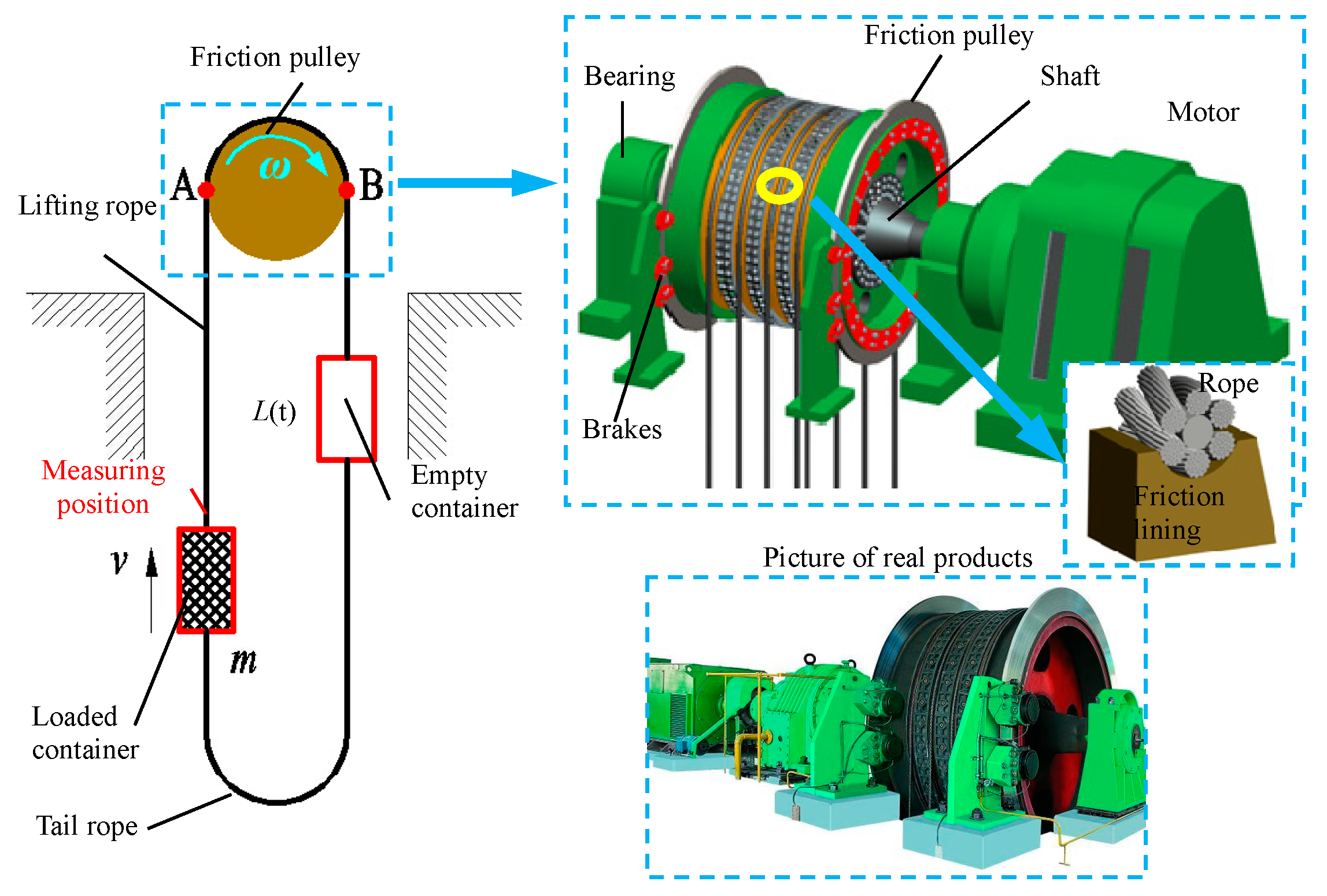
2. Hoisting Model
2.1. Hoist Equipment Parameters
2.2. Modelling Process
2.2.1. Contact Definition
2.2.2. Discrete Element Mechanics Beam
2.2.3. Parameters
3. Results
3.1. Verification Test
3.1.1. Test Scheme
3.1.2. Test Result
3.2. Suspended Rope Dynamics
3.2.1. Vibration
3.2.2. Tension
3.3. Wrapped Rope Dynamics
3.3.1. Rope Dynamics in the Wrapping Process
3.3.2. Local Friction and Contact
4. Discussion
4.1. Position Difference of Vibration Intensity
4.2. New Theory of Friction Transmission
5. Conclusions
Author Contributions
Funding
Conflicts of Interest
References
- Guo, Y.B.; Zhang, D.K.; Chen, K.; Feng, C.A.; Ge, S.R. Longitudinal dynamic characteristics of steel wire rope in a friction hoisting system and its coupling effect with friction transmission. Tribol. Int. 2018, 119, 731–743. [Google Scholar] [CrossRef]
- Guo, Y.B.; Zhang, D.K.; Yang, X.H.; Feng, C.A.; Ge, S.R. Experimental research on effect of wire rope transverse vibration on friction transmission stability in a friction hoisting system. Tribol. Int. 2017, 115, 233–245. [Google Scholar] [CrossRef]
- Wang, J.; Pi, Y.J.; Hu, Y.M.; Gong, X.S. Modeling and dynamic behavior analysis of a coupled multi-cable double drum winding hoister with flexible guides. Mech. Mach. Theory 2017, 108, 191–208. [Google Scholar] [CrossRef]
- Yao, J.N.; Xiao, X.M.; Peng, A.H.; Jiang, Y.Q.; Ma, C. Assessment of safety for axial fluctuations of head sheaves in mine hoist based on coupled dynamic model. Eng. Fail. Anal. 2015, 51, 98–107. [Google Scholar] [CrossRef]
- Yao, J.N.; Xiao, X.M. Effect of hoisting load on transverse vibrations of hoisting catenaries in floor type multirope friction mine hoists. Shock Vib. 2016, 2016, 8598749. [Google Scholar] [CrossRef]
- Wolny, S. Braking Distance of Hoist Conveyances Required for Safe Stopping Under the Conditions of Emergency Braking. Arch. Min. Sci. 2017, 62, 279–288. [Google Scholar] [CrossRef][Green Version]
- Wolny, S. Emergency Braking of a Mine Hoist in the Context of the Braking System Selection. Arch. Min. Sci. 2017, 62, 45–54. [Google Scholar] [CrossRef][Green Version]
- Gaiko, N.V.; Van Horssen, W.T. Resonances and vibrations in an elevator cable system due to boundary sway. J. Sound Vib. 2018, 424, 272–292. [Google Scholar] [CrossRef]
- Wu, J.; Kou, Z.M.; Liang, M.; Wu, G.X. Analysis and experiment of rope transverse vibration for multi-rope friction hoisting system. J. Huazhong Univ. Sci. Tech. 2015, 12–16. [Google Scholar] [CrossRef]
- Bao, J.H.; Zhang, P.; Zhu, C.M.; Zhu, M. Nonlinear Vibration Analysis of Flexible Hoisting Rope with Time-Varying Length. Int. J. Acoust. Vib. 2015, 20, 160–170. [Google Scholar] [CrossRef]
- Kaczmarczyk, S.; Ostachowicz, W. Transient vibration phenomena in deep mine hoisting cables. Part 1: Mathematical model. J. Sound Vib. 2003, 262, 219–244. [Google Scholar] [CrossRef]
- Kaczmarczyk, S.; Ostachowicz, W. Transient vibration phenomena in deep mine hoisting cables. Part 2: Numerical simulation of the dynamic response. J. Sound Vib. 2003, 262, 245–289. [Google Scholar] [CrossRef]
- Zhu, W.D.; Ren, H. An accurate spatial discretization and substructure method with application to moving elevator cable-car systems-Part I: Methodology. J. Vib. Acoust. 2013, 135, 4024557. [Google Scholar] [CrossRef]
- Ren, H.; Zhu, W.D. An accurate spatial discretization and substructure method with application to moving elevator cable-car systems-Part II: Application. J. Vib. Acoust. 2013, 135, 1127–1139. [Google Scholar] [CrossRef]
- Bao, J.H.; Zhang, P.; Zhu, C.M. Longitudinal vibration of rope hoisting systems with time-varying length. J. Vib. Shock. 2013, 32, 173–177. [Google Scholar]
- Bao, J.H.; Zhang, P.; Zhu, C.M. Modeling and control of longitudinal vibration on flexible hoisting systems with time-varying length. Procedia Eng. 2011, 15, 4521–4526. [Google Scholar] [CrossRef][Green Version]
- Yang, D.H.; Kim, K.Y.; Kwak, M.K.; Lee, S.J. Dynamic modeling and experiments on the coupled vibrations of building and elevator ropes. J. Sound Vib. 2017, 390, 164–191. [Google Scholar] [CrossRef]
- Wu, J.; Kou, Z.M.; Liang, M.; Wu, G.X. Analysis of longitudinal and transverse coupling vibration of steel wire rope in friction hoisting system. J. China Univ. Min. Tech. 2015, 44, 885–892. [Google Scholar] [CrossRef]
- Lubarda, V.A. Determination of the belt force before the gross slip. Mech. Mach. Theory. 2015, 83, 31–37. [Google Scholar] [CrossRef]
- Guo, Y.B.; Zhang, D.K.; Feng, C.A.; Liu, Y. Dynamic creeping behaviors between hoisting rope and friction lining in friction transmission. J. Vibroeng. 2016, 18, 5010–5028. [Google Scholar] [CrossRef]
- Wang, D.G.; Zhang, D.K.; Mao, X.B.; Peng, Y.X.; Ge, S.R. Dynamic friction transmission and creep characteristics between hoisting rope and friction lining. Eng. Fail. Anal. 2015, 57, 499–510. [Google Scholar] [CrossRef]
- Przemieniecki, J.S. Theory of Matrix Structural Analysis; McGraw-Hill Book Company: New York, NY, USA, 1968. [Google Scholar]
- Guo, Y.B.; Zhang, D.K.; Wang, D.G.; Liu, Y.; Feng, C.A. Dynamic distribution of contact stress of friction lining in the process of friction transmission. J. Vibroeng. 2016, 18, 4207–4221. [Google Scholar] [CrossRef]
- Wang, D.G.; Wang, D.A. Dynamic contact characteristics between hoisting rope and friction lining in the deep coal mine. Eng. Fail. Anal. 2016, 64, 44–57. [Google Scholar] [CrossRef]
- Pietra, L.D.; Timpone, F. Tension in a flat belt transmission: Experimental investigation. Mech. Mach. Theory 2013, 70, 129–156. [Google Scholar] [CrossRef]
- Ma, W.; Lubrecht, A.A. Detailed contact pressure between wire rope and friction lining. Tribol. Int. 2017, 109, 238–245. [Google Scholar] [CrossRef]
- Ma, W.; Zhu, Z.C.; Xu, L.; Chen, G.A. Sliding friction and wear properties of friction linings with friction-promoting grease applied. Proc. Inst. Mech. Eng. Part J J. Eng. Tribol. 2014, 228, 595–607. [Google Scholar] [CrossRef]


| Item | Unit | Friction Pulley | Guide Pulley | ||
| Hoist | Type | JKM-5 × 6 | |||
| Lifting height | m | 425 | |||
| Pulleys Spacing | m | Vertical:13/horizontal:3.35 | |||
| Diameter | m | 5 | 5 | ||
| Number | 6 | 6 | |||
| Friction coefficient | 0.25 | 0.25 | |||
| wrap angle | ° | 187.42 | |||
| Item | Unit | Hoisting rope | Tail rope | ||
| Rope | Type | 54 × 36WS + FC | 216 × 34 × 4 × 19 + FC | ||
| Diameter/Width × Thickness | mm | 54 | 216 × 34 | ||
| Number | 6 | 3 | |||
| Density | kg/mm3 | 4.72 × 10⁻⁶ | 23 | ||
| Total length | m | 523.08 | 481.5 | ||
| Item | Unit | ||||
| Load | Cage mass | kg | 0.65 × 10⁵ | ||
| Balance hammer mass | 0.95 × 10⁵ | ||||
| Test load(total) | MAX | 1.2 × 10⁵ | |||
| MID | 0.95 × 10⁵ (mainly discussed) | ||||
| MIN | 0.7 × 10⁵ | ||||
| Stage | Acceleration (m/s2) | Speed (m/s) | Time (s) | |
|---|---|---|---|---|
| Main acceleration | Varying | 0~0.6 | 0.51 | 1.71 |
| Constant | 0.6 | 9.43 | 14.87 | |
| Varying | 0.6~0 | 9.95 | 1.71 | |
| Total | 18.29 | |||
| Constant speed | Constant | 0 | 9.95 | 24.45 |
| Item | Unit | Value | |
|---|---|---|---|
| Pulleys | Diameter | m | 5 |
| Centre distance | m | Vertical 13, horizontal 3.35 | |
| Width | mm | 600 | |
| Rope groove | Depth | mm | 50 |
| Radius | mm | 27 | |
| Angle | ° | 20 | |
| Contact | Friction coefficient | 0.25 | |
| Hertz k/e/cmax | 10,000/2/0.1 | ||
| Rope | Diameter | mm | 54 |
| Density | Kg/mm3 | 4.72 × 10⁻⁶ | |
| Elastic modulus | MPa | 1.15 × 10⁵ | |
| Tensile(Rkx)/Bending(Rkb)/Torsional (Rkt)stiffness coefficient | 1.0/0.001/0.01 | ||
| Damping | 0.01 | ||
| Discrete number | 1701 |
© 2020 by the authors. Licensee MDPI, Basel, Switzerland. This article is an open access article distributed under the terms and conditions of the Creative Commons Attribution (CC BY) license (http://creativecommons.org/licenses/by/4.0/).
Share and Cite
Guo, Y.; Zhang, D.; Zhang, X.; Wang, D.; Wang, S. A New Transmission Theory of “Global Dynamic Wrap Angle” for Friction Hoist Combining Suspended and Wrapped Wire Rope. Appl. Sci. 2020, 10, 1305. https://doi.org/10.3390/app10041305
Guo Y, Zhang D, Zhang X, Wang D, Wang S. A New Transmission Theory of “Global Dynamic Wrap Angle” for Friction Hoist Combining Suspended and Wrapped Wire Rope. Applied Sciences. 2020; 10(4):1305. https://doi.org/10.3390/app10041305
Chicago/Turabian StyleGuo, Yongbo, Dekun Zhang, Xinyue Zhang, Dagang Wang, and Songquan Wang. 2020. "A New Transmission Theory of “Global Dynamic Wrap Angle” for Friction Hoist Combining Suspended and Wrapped Wire Rope" Applied Sciences 10, no. 4: 1305. https://doi.org/10.3390/app10041305
APA StyleGuo, Y., Zhang, D., Zhang, X., Wang, D., & Wang, S. (2020). A New Transmission Theory of “Global Dynamic Wrap Angle” for Friction Hoist Combining Suspended and Wrapped Wire Rope. Applied Sciences, 10(4), 1305. https://doi.org/10.3390/app10041305