Forced Convection Heat Transfer for Stratospheric Airship Involved Flight State


Abstract
:1. Introduction
2. Numerical Method
2.1. Geometric Model
2.2. Control Equations
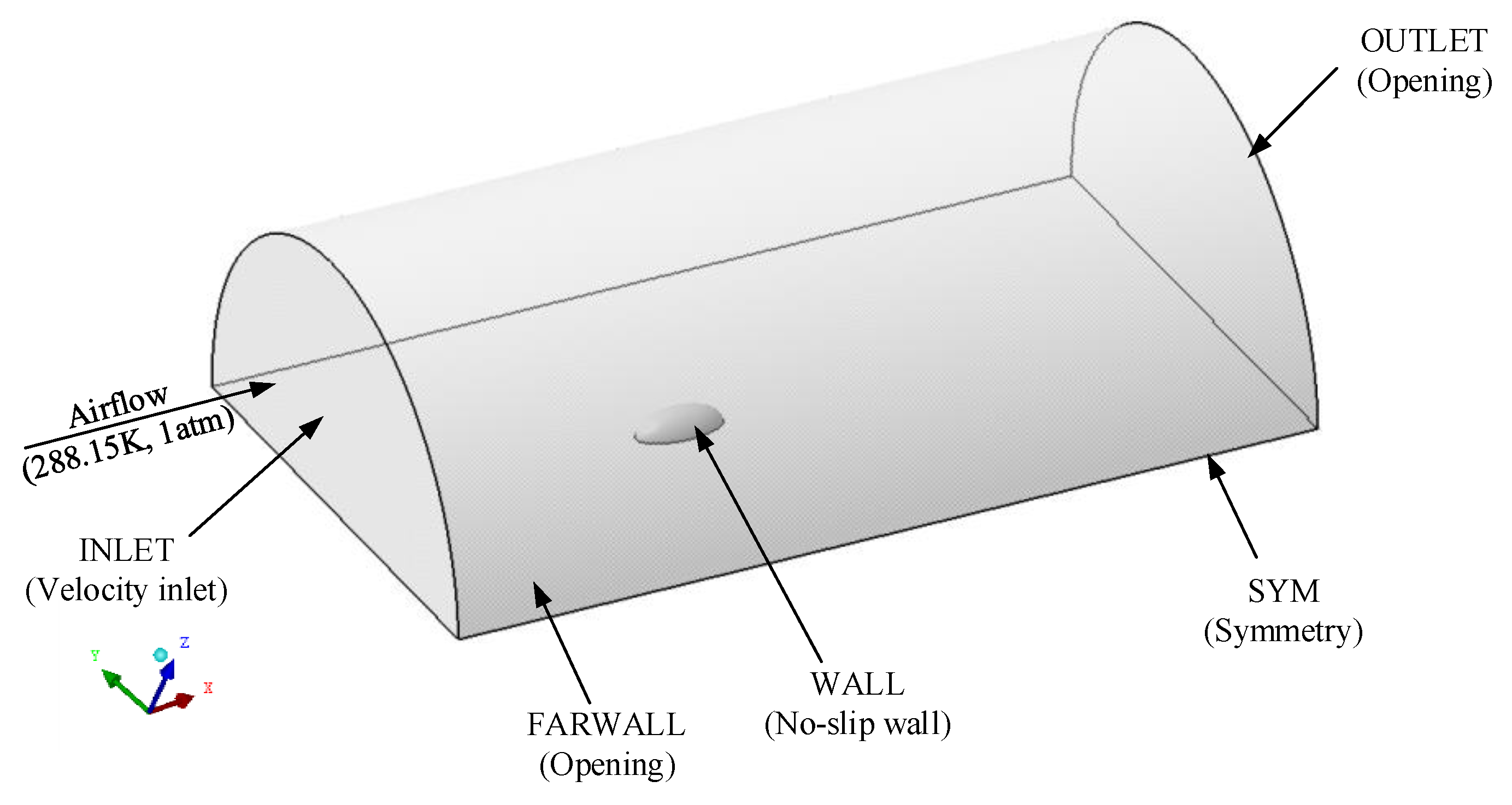
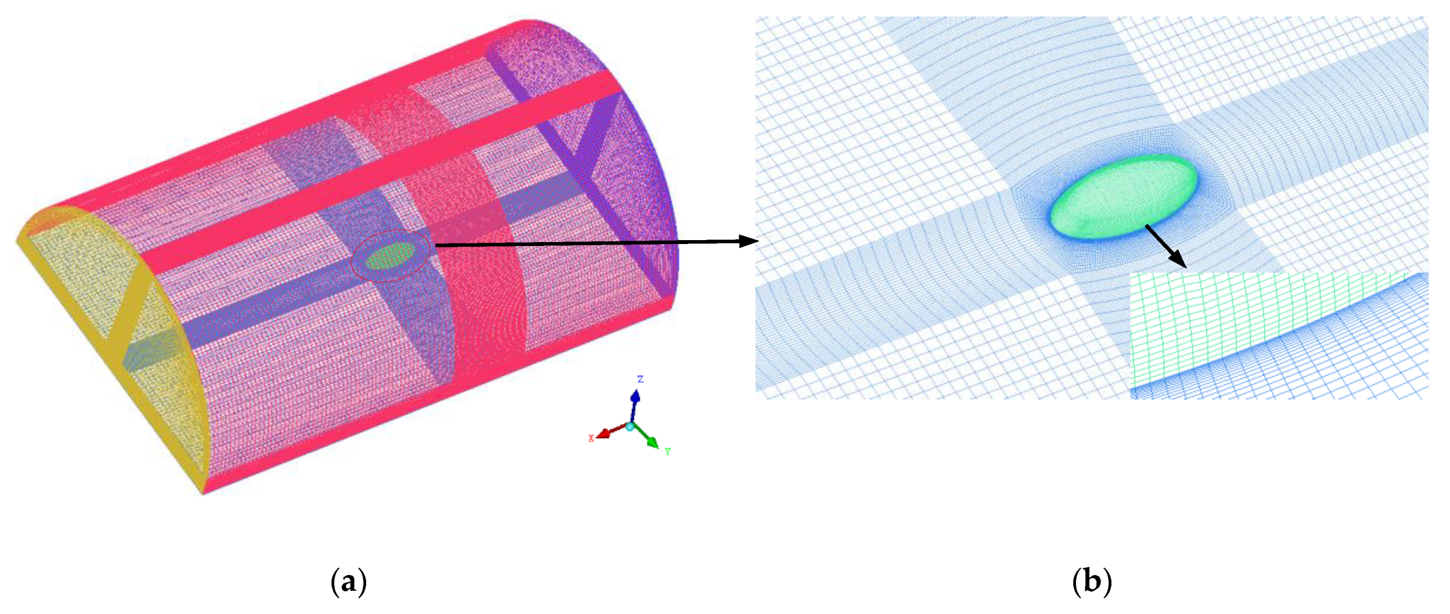
2.3. Computational Domains, Mesh, and Boundary Condition
2.4. Turbulence Model
3. Results and Discussions
3.1. Effects of Different Parameters on Heat Transfer
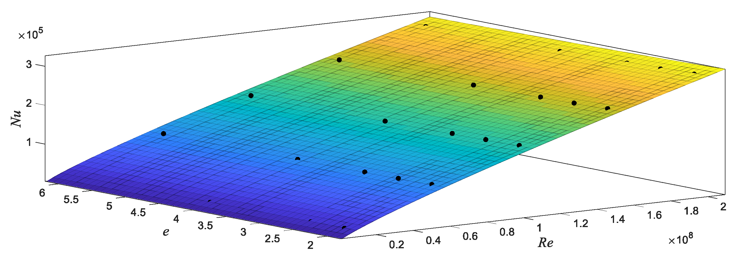
3.2. Formula Fitting
3.2.1. Horizontal State
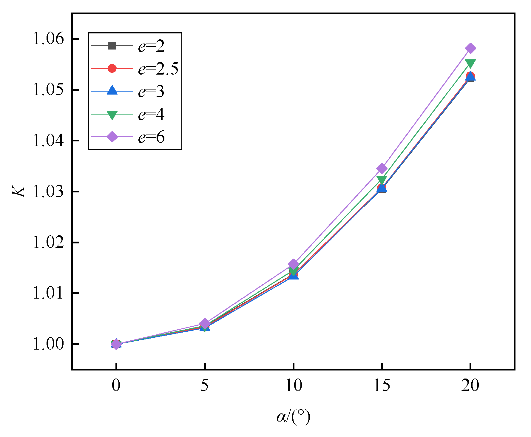
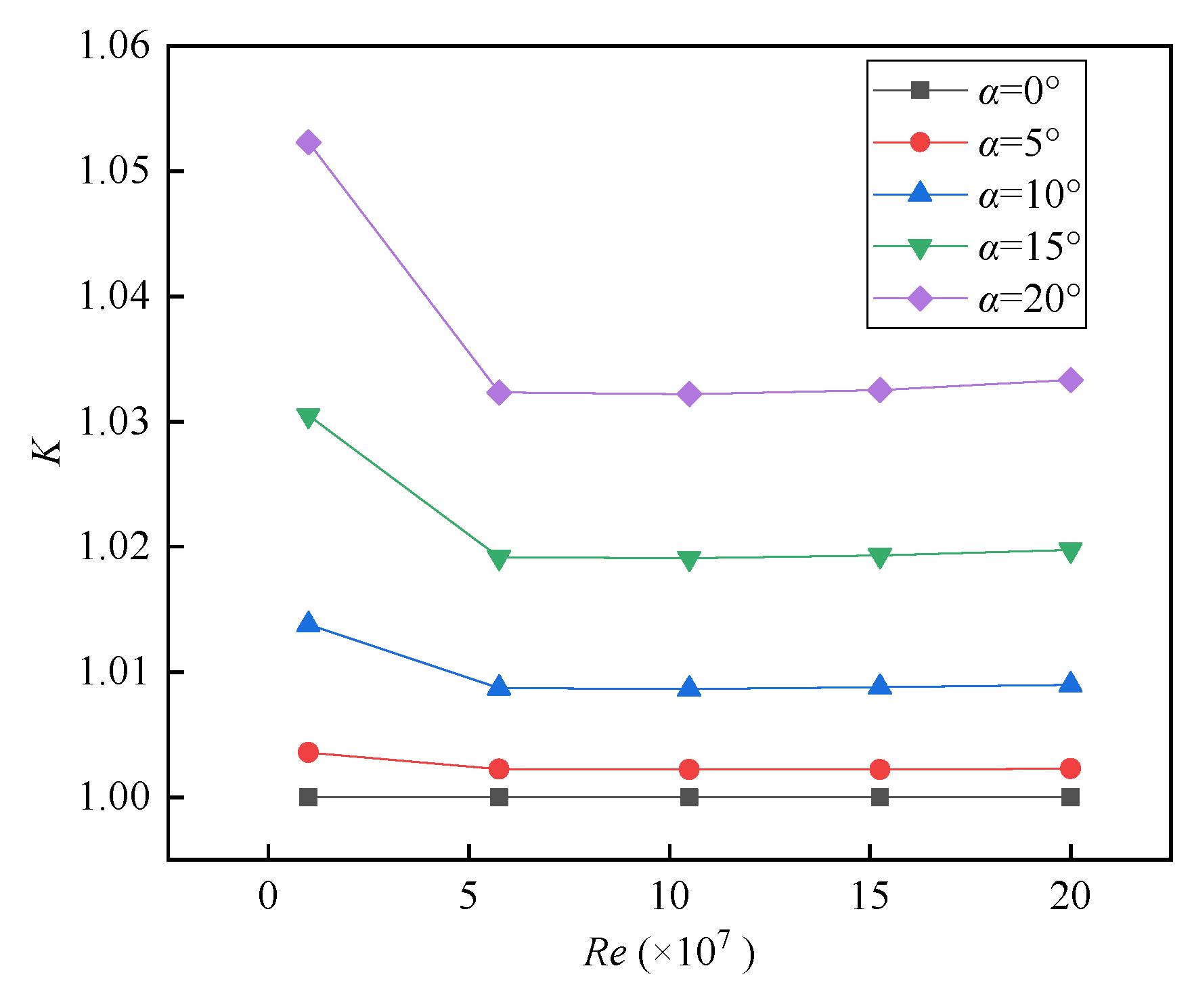
3.2.2. State Modification
4. Conclusions
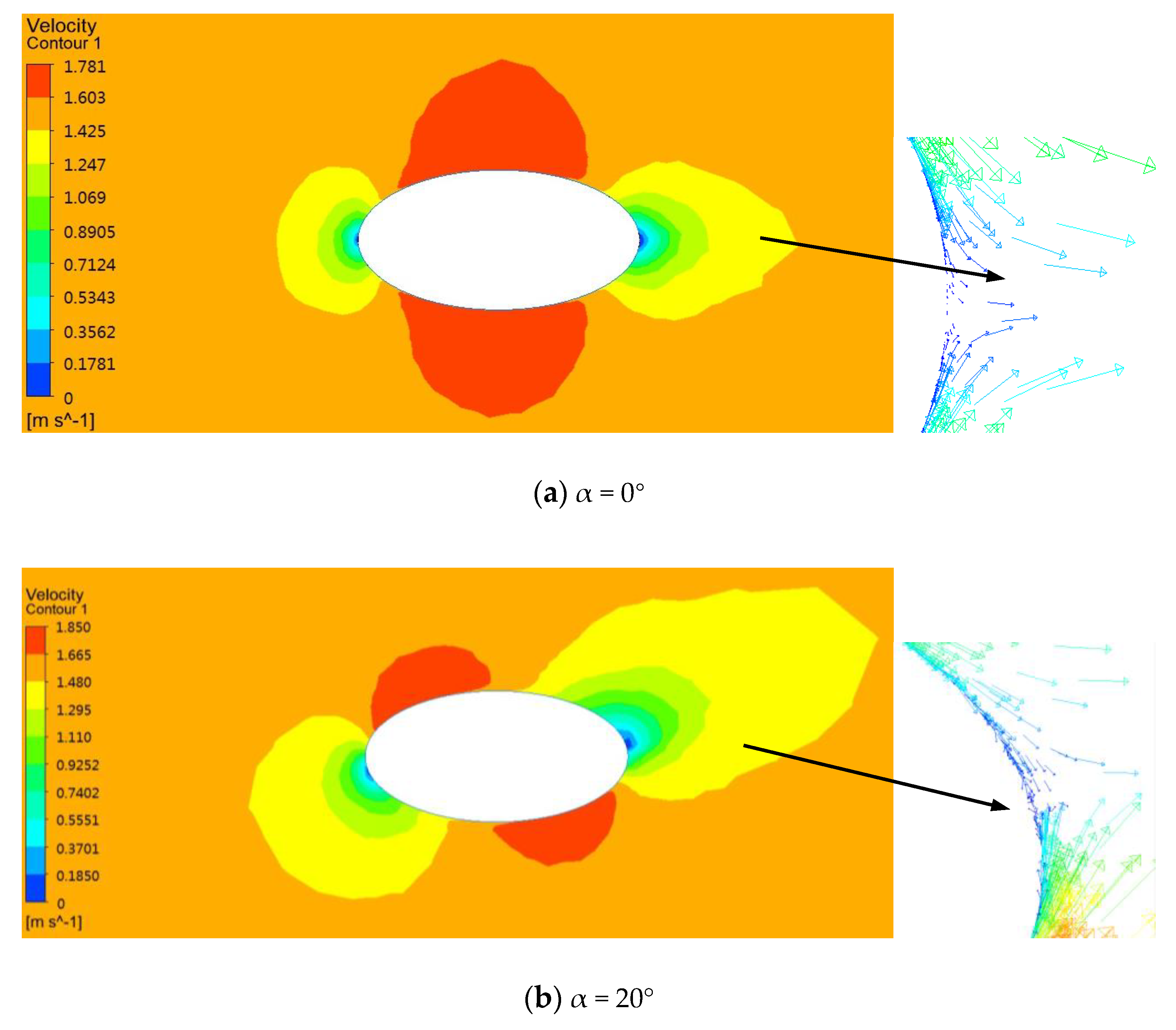
- (1)
- The change of flow field structure around the airship is the root reason for the change of forced convection heat transfer.
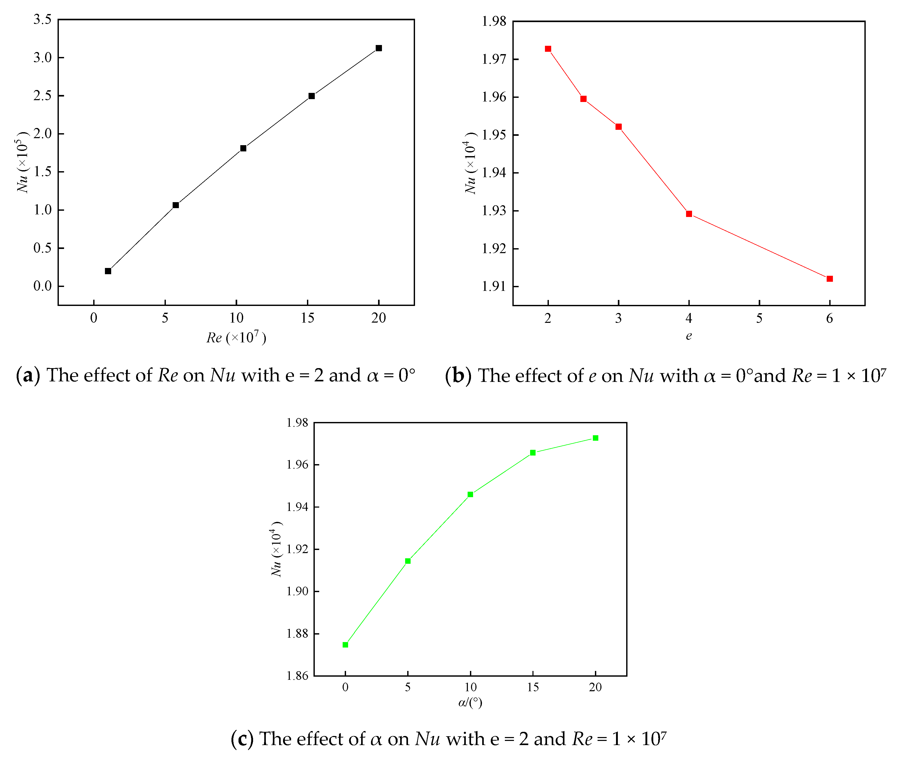
- (2)
- The average Nusselt number increases with the increase of Re (1 × 10⁷ to 2.0 × 10⁸), decreases with the increase of e (2 to 6), and increases with the increase of α (0 to 20°).
- (3)
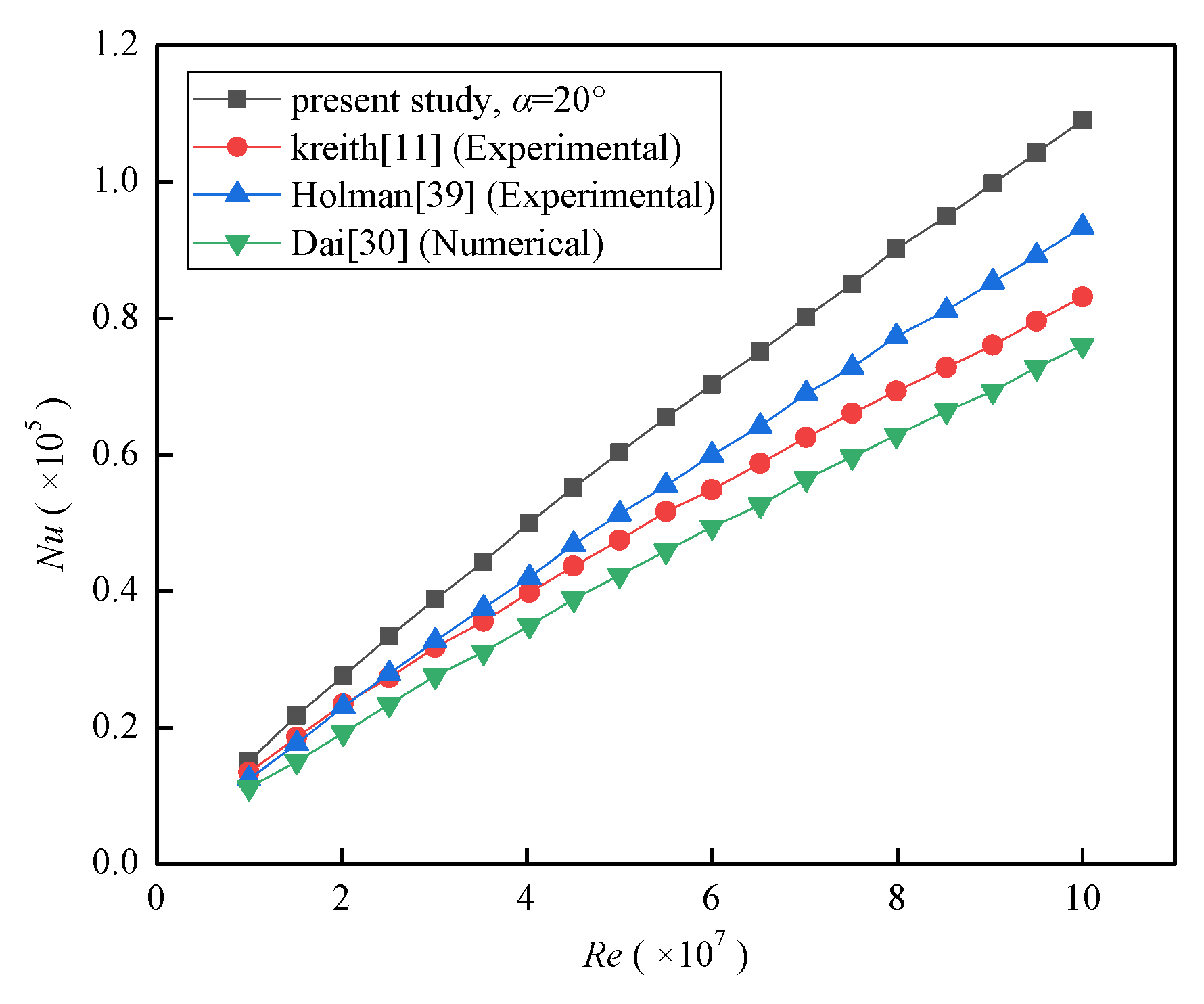
- In the present study, the results show a similar performance trend with the existing correlations, and at higher Reynolds number, the results of the present study are higher by 30 percent than those of Dai with α = 20°.
- (4)
- K increases with the increase of e and α, and the results with α = 20° have about a 6 percent difference than that without angle of attack. Flight state is an important factor to be considered in the thermal design period of an ellipsoidal airship.
Author Contributions
Funding
Acknowledgments
Conflicts of Interest
References
- Santapietro, J.J. Persistent wide area surveillance from an airship. IEEE Aerosp. Electron. Syst. Mag. 2012, 27, 11–16. [Google Scholar] [CrossRef]
- Izet-Ünsalan, K.; Ünsalan, D. A Low Cost Alternative for Satellites-Tethered Ultra-High Altitude Balloons. In Proceedings of the 5th International Conference on Recent Advances in Space Technologies-RAST2011, Istanbal, Turkey, 9–11 June 2011. [Google Scholar]
- Lee, M.; Smith, I.; Androulakakis, S. The High-Altitude Lighter than Air Airship Efforts at the US Army Space and Missile Defense Command/Army Forces Strategic Command. In Proceedings of the 18th AIAA Lighter-than-air Systems Technology Conference, Washington, DC, USA, 4–7 May 2009. [Google Scholar]
- Sarafraz, M.M.; Hormozi, F. Intensification of forced convection heat transfer using biological nanofluid in a double-pipe heat exchanger. Exp. Therm. Fluid Sci. 2015, 66, 279–289. [Google Scholar] [CrossRef]
- Peyghambarzadeh, S.M.; Sarafraz, M.M.; Vaeli, N.; Ameri, E.; Vatani, A.; Jamialahmadi, M. Forced convective and subcooled flow boiling heat transfer to pure water and n-heptane in an annular heat exchanger. Ann. Nucl. Energy 2013, 53, 401–410. [Google Scholar] [CrossRef]
- Moore, D.; Newport, D.; Egan, V.; Lacarac, V.J.A.T.E. Ventilation and internal structure effects on naturally induced flows in a static aircraft wing. Appl. Therm. Eng. 2012, 32, 49–58. [Google Scholar] [CrossRef]
- Petersen, D.; Rolfes, R.; Zimmermann, R. Thermo-mechanical design aspects for primary composite structures of large transport aircraft. Aerosp. Sci. Technol. 2001, 5, 135–146. [Google Scholar] [CrossRef]
- Storch, D.R. Systems and Methods for A Passive, Forced Convection Cooling System. U.S. Patent Application 12/116786, 12 October 2009. [Google Scholar]
- Karabelas, S.J.; Markatos, N.C. Water vapor condensation in forced convection flow over an airfoil. Aerosp. Sci. Technol. 2008, 12, 150–158. [Google Scholar] [CrossRef]
- Sarafraz, M.M.; Hormozi, F. Forced convective and nucleate flow boiling heat transfer to alumina nanofluids. Period. Polytech. Chem. Eng. 2014, 58, 37–46. [Google Scholar] [CrossRef] [Green Version]
- Kreith, F.; Kreider, F. Numerical Prediction of the Performance of High Altitude Balloons; NCAR Technical Note NCAR-IN/STR-65; NCAR: Boulder, CO, USA, 1974. [Google Scholar]
- Yao, W.; Lu, X.; Wang, C.; Ma, R. A heat transient model for the thermal behavior prediction of stratospheric airships. Appl. Therm. Eng. 2014, 70, 380–387. [Google Scholar] [CrossRef]
- Wu, J.; Fang, X.; Wang, Z.; Hou, Z.; Ma, Z.; Zhang, H.; Dai, Q.; Xu, Y. Thermal modeling of stratospheric airships. Prog. Aerosp. Sci. 2015, 75, 26–37. [Google Scholar] [CrossRef]
- Alam, M.I.; Pant, R.S. A multi-node model for transient heat transfer analysis of stratospheric airships. Adv. Space Res. 2017, 59, 3023–3035. [Google Scholar] [CrossRef]
- Fang, X.; Wang, W.; Li, X. A Study of Thermal simulation of stratospheric airships. Spacecr. Recovery Remote Sens. 2007, 28, 5–9. [Google Scholar]
- Wang, Y.; Yang, C. A comprehensive numerical model examining the thermal performance of airships. Adv. Space Res. 2011, 48, 1515–1522. [Google Scholar] [CrossRef]
- Dai, Q.; Fang, X.; Xu, Y. Numerical study of forced convective heat transfer around a spherical aerostat. Adv. Space Res. 2013, 52, 2199–2203. [Google Scholar] [CrossRef]
- Alam, M.I.; Pant, R.S. Modeling Transient Heat Transfer in Stratospheric Airships. In Proceedings of the 15th AIAA Aviation Technology, Integration, and Operations Conference, Washington, DC, USA, 22–26 June 2015. [Google Scholar]
- Xia, X.L.; Li, D.F.; Sun, C.; Ruan, L.M. Transient thermal behavior of stratospheric balloons at float conditions. Adv. Space Res. 2010, 46, 1184–1190. [Google Scholar] [CrossRef]
- Whitaker, S. Forced convection heat transfer correlations for flow in pipes, past flat plates, single cylinders, single spheres, and for flow in packed beds and tube bundles. Aiche J. 1972, 18, 361–371. [Google Scholar] [CrossRef]
- Shi, H.; Zhang, T.; Gao, Z.; Pei, H. Research on fixed point thermal characteristics of a new stratospheric airship. J. Mech. Eng. 2018, 54, 154–161. [Google Scholar] [CrossRef]
- Shi, H.; Geng, S.; Qian, X. Thermodynamics analysis of a stratospheric airship with hovering capability. Appl. Therm. Eng. 2019, 146, 600–607. [Google Scholar] [CrossRef]
- Wu, J.; Ma, Z.; Hou, Z.; Liu, Z. Numerical research on forced convective heat transfer of stratospheric airship. J. Natl. Univ. Def. Technol. 2016, 38, 177–182. [Google Scholar]
- Liu, Q.; Xu, S.; Zhong, W.; Yang, J.; Liu, M. A heat transfer empirical correlation for the stratospheric airship. J. Univ. Sci. Technol. China 2013, 43, 387–392. [Google Scholar] [CrossRef]
- Riemann, B. Ueber Die Hypothesen, Welche der Geometriezu Grunde Liegen; University of Gottingen: Gottingen, Germany, 1854. [Google Scholar]
- Snyder, W.H. Similarity Criteria for the Application of Fluid Models to the Study of Air Pollution Meteorology. Bound. Layer Meteorol. 1972, 3, 113–134. [Google Scholar] [CrossRef]
- Townsend, A.A.R. The Structure of Turbulent Shear Flow, 2rd ed.; Cambridge University Press: Cambridge, UK, 1980; p. 200. [Google Scholar]
- Kishore, N.; Gu, S. Momentum and heat transfer phenomena of spheroid particles at moderate Reynolds and Prandtl numbers. Int. J. Heat Mass Transf. 2011, 54, 2595–2601. [Google Scholar] [CrossRef]
- Karabelas, S.J.; Koumroglou, B.C.; Argyropoulos, C.D.; Markatos, N.C. High Reynolds number turbulent flow past a rotating cylinder. Appl. Math. Model. 2012, 36, 379–398. [Google Scholar] [CrossRef]
- Dai, Q.; Fang, X. Numerical study of forced convective heat transfer around airships. Adv. Space Res. 2016, 57, 776–781. [Google Scholar] [CrossRef]
- Amchenbach, E. Experiments on the flow past spheres at very high Reynolds numbers. Fluid Mech. 1972, 54, 565–575. [Google Scholar] [CrossRef]
- Hsu, C.J. Heat transfer to liquid metals flowing past spheres and elliptical-rod bundles. Int. J. Heat Mass Transf. 1964, 8, 303–315. [Google Scholar] [CrossRef]
- Sideman, S. The equivalence of the penetration and potential flow theories. Ind. Eng. Chem. 1966, 58, 54–58. [Google Scholar] [CrossRef]
- Melissari, B.; Argyropoulos, S.A. Development of a heat transfer dimensionless correlation for spheres immersed in a wide range of Prandtl number fluids. Int. J. Heat Mass Transf. 2005, 48, 4333–4341. [Google Scholar] [CrossRef]
- Lee, S. A numerical study of the unsteady wake behind a sphere in a uniform flow at moderate Reynolds numbers. Comput. Fluids 1999, 29, 639–667. [Google Scholar] [CrossRef]
- Leder, A.; Geropp, D. Unsteady flow structure in the wake of the sphere. Int. Soc. Opt. Eng. 1993, 2052, 119–126. [Google Scholar]
- Pao, H.P.; Kao, T.W. Vortex structure in the wake of a sphere. Phys. Fluids 1977, 20, 187. [Google Scholar] [CrossRef]
- Li, Y.; Yang, Y.; Zhou, J.; Wang, S. Analysation of changes of pitch angle during formatted launch process of stratospheric airship. Comput. Simul. 2014, 31, 45–49. [Google Scholar]
- Holman, J.P. Heat Transfer, 8th ed.; Mc Graw-Hill Book Co.: New York, NY, USA, 1997; pp. 282–283. [Google Scholar]


| L = 100/(m) | |||||
|---|---|---|---|---|---|
| E = L/D | 2 | 2.5 | 3 | 4 | 6 |
| D/(m) | 50 | 40 | 33.33 | 25 | 16.67 |
| Parameters | Values | ||||
|---|---|---|---|---|---|
| 1 | 2 | 3 | 4 | 5 | |
| Re (×108) | 0.1 | 0.575 | 1.05 | 1.53 | 2.0 |
| e | 2 | 2.5 | 3 | 4 | 5 |
| α/(°) | 0 | 5 | 10 | 15 | 20 |
| c1 | c2 | c3 |
|---|---|---|
| 0.0161 | 0.8543 | −0.0454 |
| e | Re | Calculated Results by Formula (6) | Numerical Results by CFD | Error/(%) |
|---|---|---|---|---|
| 2.2 | 1 × 10⁷ | 14,838 | 14,989 | 1.01 |
| 3.75 | 5.75 × 10⁷ | 64,543 | 63,685 | 1.33 |
| 4.25 | 5.75 × 10⁷ | 64,177 | 63,202 | 1.52 |
| 5.3 | 2.0 × 10⁸ | 184,295 | 18,4979 | 0.37 |
| e | Re | α/(°) | Calculated Results by Formula (9) | Numerical Results by CFD | Error/(%) |
|---|---|---|---|---|---|
| 2.2 | 1 × 10⁷ | 5 | 14,855 | 15,077 | 1.47 |
| 3.75 | 5.75 × 10⁷ | 10 | 65,254 | 64,410 | 1.31 |
| 4.25 | 5.75 × 10⁷ | 10 | 64,915 | 65,923 | 1.53 |
| 5.3 | 2.0 × 10⁸ | 20 | 193,524 | 18,792 | 2.98 |
© 2020 by the authors. Licensee MDPI, Basel, Switzerland. This article is an open access article distributed under the terms and conditions of the Creative Commons Attribution (CC BY) license (http://creativecommons.org/licenses/by/4.0/).
Share and Cite
Pei, H.; Kong, B.; Jiang, Y.; Shi, H. Forced Convection Heat Transfer for Stratospheric Airship Involved Flight State. Appl. Sci. 2020, 10, 1294. https://doi.org/10.3390/app10041294
Pei H, Kong B, Jiang Y, Shi H. Forced Convection Heat Transfer for Stratospheric Airship Involved Flight State. Applied Sciences. 2020; 10(4):1294. https://doi.org/10.3390/app10041294
Chicago/Turabian StylePei, Houju, Benben Kong, Yanlong Jiang, and Hong Shi. 2020. "Forced Convection Heat Transfer for Stratospheric Airship Involved Flight State" Applied Sciences 10, no. 4: 1294. https://doi.org/10.3390/app10041294
APA StylePei, H., Kong, B., Jiang, Y., & Shi, H. (2020). Forced Convection Heat Transfer for Stratospheric Airship Involved Flight State. Applied Sciences, 10(4), 1294. https://doi.org/10.3390/app10041294