Review

Advances in Micromanipulation Actuated by Vibration-Induced Acoustic Waves and Streaming Flow

1
Key Laboratory of Biomimetic Robots and Systems, Ministry of Education, State Key Laboratory of Intelligent Control and Decision of Complex System, Beijing Advanced Innovation Center for Intelligent Robots and Systems, and School of Mechatronical Engineering, Beijing Institute of Technology, Beijing 100081, China
2
Department of Materials Engineering Science, Osaka University, Osaka 560-8531, Japan
3
Global Alliance Laboratory, The University of Electro-Communications, Tokyo 182-8585, Japan
*
Author to whom correspondence should be addressed.
Appl. Sci. 2020, 10(4), 1260; https://doi.org/10.3390/app10041260
Submission received: 31 December 2019 / Revised: 4 February 2020 / Accepted: 10 February 2020 / Published: 13 February 2020

Abstract

:
The use of vibration and acoustic characteristics for micromanipulation has been prevalent in recent years. Due to high biocompatibility, non-contact operation, and relatively low cost, the micromanipulation actuated by the vibration-induced acoustic wave and streaming flow has been widely applied in the sorting, translating, rotating, and trapping of targets at the submicron and micron scales, especially particles and single cells. In this review, to facilitate subsequent research, we summarize the fundamental theories of manipulation driven by vibration-induced acoustic waves and streaming flow. These methods are divided into two types: actuated by the acoustic wave, and actuated by the steaming flow induced by vibrating geometric structures. Recently proposed representative vibroacoustic-driven micromanipulation methods are introduced and compared, and their advantages and disadvantages are summarized. Finally, prospects are presented based on our review of the recent advances and developing trends.

1. Introduction

Since the first microparticle manipulation method based on optical techniques proposed by Ashkin et al. in 1986 [1], micromanipulation has shown potential in the translation, rotation, pattern, sorting, and separation of particles or cells. In particular, some cell-oriented manipulations, such as cell–cell interaction, cell injection, physical transfection, have been achieved. Micromanipulation via optical techniques named optical tweezers [1] has achieved success and is now the primary tool used in the scientific community. However, consensus has been reached that the benefits of optical tweezers come at the cost of expense, complexity, inefficiency, and potential damage to cells [2], so the applications of such devices are limited. The emergence of lab-on-a-chip technology has motivated effort to replace optical tweezers in recent years [3]. Many alternative manipulation methods have been developed using magnetic [4], dielectrophoretic (DEP) [5], optoelectronic [6], and acoustic [7] methods. Acoustic field and vibration provide an essential tool for accurate, biocompatible, and non-contact manipulation of cells and microparticles, so they have received considerable attention more recently. As a means of manipulating orientation of micron-scale objects such as particles and cells, micro-manipulating devices actuated by vibration will have lower operating costs and be more reconfigurable, flexible, versatile, and biocompatible in the future. For its development, especially in practical applications, achieving a more comprehensive, extensive, and profound understanding of vibration actuated manipulations is vital. Notably, vibroacoustic methods cannot manipulate molecular-scale particles like optical or magnetic methods, as stated in the review by Neuman et al. [8] and Shi et al. [9]. Due to the diffraction phenomenon caused by acoustic wavelengths and the highly nonlinear characteristics of fluid on the nanometer scale, the effective range of vibroacoustic manipulation is generally limited to the micron or submicron scale, which is also the scale mainly studied in this review. Since these micromanipulation schemes are usually actuated by vibro-acoustic phenomena, we refer to the concept of micromanipulation actuated by acoustic waves and streaming flow as vibration-induced acoustic wave (VAW) and vibration-induced streaming flow (VSF), respectively. VAW and VSF are two different vibration-induced physical phenomena. Acoustic radiation force (ARF) and acoustic stream are the two main mechanisms of VAW, referred to as acoustophoresis [10]. Due to the scattering between particles in the medium, an acoustic field forms in the propagation of VAW, where a radiation force exists in the gradient direction [11]. A difference exists between acoustic streaming and VSF. Here, acoustic stream refers explicitly to the phenomenon of nonlinear acoustic force propagation caused by second-order sound pressure. Although the acoustic stream is a widespread phenomenon, its performance usually needs to meet two conditions: high frequency vibration and appropriate particle size. VSF is generated by the action of a Reynolds stress, defined as the mean value of the acoustic momentum flux [12]. Streaming flow has no strict requirements for high vibration frequency and particle diameter. In other words, vibration is not a sufficient condition for streaming flow. However, VAW and VSF often occur simultaneously and are difficult to eliminate their mutual influence. To ensure the operability and achieve the desired effect, we discuss the physical principles of the two mechanisms above to determine and explore the functions performed by each. The principles of forces induced by the acoustic wave and streaming flow are complicated, but these issues are vital for their study. Therefore, we introduce these forces briefly in Section 2. Some typical VAW and VSF devices are shown in Figure 1.
Similar to magnetic and dielectrophoretic manipulation, VAW uses vibration to excite a wide range of acoustic fields in the medium, where gradient forces are used to manipulate the particles or cells. Acoustic radiation manipulation devices can be used for transport [13,14,15], sorting and filtering [16,17], trapping [18,19], patterning of particles or cells [20,21,22], droplet generation [23], and fusion [24]. Acoustic radiation force can be generated using many methods such as surface acoustic waves (SAWs) and bulk acoustic waves (BAWs). Micromanipulation by acoustic waves is arguably the most popular and mature research solution. The actuators of these devices are usually stationary and can generate a widely distributed acoustic field in channels or chambers. Different from the complex principle of acoustic field force, SAW and BAW are the two branches separated from each other based on the propagation forms. Compared with BAW devices, SAW devices are more diverse, including in-plane manipulating devices and acoustic actuators arrays, which results in an efficient operating process in the simultaneous transport and patterning of multiple particles. Interfaces between different media are straightforward to find, which is the basis of SAW propagation. BAW devices usually have a certain depth and stable propagation medium. BAW devices have viscous boundary layers at the fluid cavity walls that cause boundary-driven streaming on the boundary parallel to the propagation direction [25]. The existence of boundary streaming restricts the wave’s propagation in the boundary direction, which generated concentrated acoustic waves. However, numerical analysis of the BAW boundary streaming is a troublesome task. In the cross-sectional direction, BAWs can generate a Bessel vortex, where particles can be trapped in the center. The BAW devices generate acoustic beams for manipulation, which is similar to magnetic tweezers and optical tweezers, which we also label as acoustic beam actuators.
Traveling and standing acoustic waves are two different manifestations. Traveling acoustic waves propagate in a certain direction, where the particles in the traveling acoustic wave field usually move in the same direction. Standing waves are generally superimposed by traveling waves of the same frequency propagating in opposite directions, which can be generated by a reflecting plate or symmetrically arranged transducers. The superposition of two waves generates nodes or potential wells with the lowest potential energy in the acoustic field, where particles gather spontaneously. Considering both traveling and standing waves have been applied in micromanipulation, the micromanipulation based on SAW can be further divided to using traveling SAW (TSAW) and standing SAW (SSAW).TSAW and SSAW are common concepts of in-plane micromanipulation. One of the important characteristics of micromanipulation based on BAWs is using high-frequency vibration to induce ultrasonic waves. Thus, to emphasize the high frequency used, the micromanipulation based on BAWs can be divided to manipulation by ultrasonic traveling waves (UTWs) and ultrasonic standing waves (USWs) [26,27].
Figure 1. Schematic diagrams of several typical (ad) vibration-induced acoustic wave (VAW) and (eg) vibration-induced streaming flow (VSF)devices (introduced in Section 4): (a) cell sorting device based on traveling surface acoustic wave (TSAW) [16], which is a widely used scheme; (b) dynamic acoustic field micromanipulation device based on standing surface acoustic wave (SSAW). (a,b) Typical SAW devices, which will be introduced in Section 3.1. (c) Ultrasonic acoustic beam actuator using bulk acoustic wave (BAW). (d) One-dimensional (1D) ultrasonic acoustic transducers array manipulator. (c,d) Typical BAW devices, which will be introduced in Section 3.2. (e) Vibrated needle manipulation; (f) vibrated geometric substrate manipulation systems [10]. (g) Manipulation by vibrated microbubble induced microflow.
Applsci 10 01260 g001
Different from the use of acoustic actuators to generate ultrasonic waves for operation, the high-frequency vibration of a certain geometric structure can be used to generate acoustic streaming, medium flow, or vortexes—the VSF devices. Compared with the method mentioned above, VSF devices can achieve more complex functions that focus on single particles such as translation, rotation, trapping, localization, and orientation. VSF is less constrained by particle volume and shape, and system design is relatively easier. Many of these systems can perform different tasks without making changes, as exemplified by Liu et al. [28,29], Li et al. [30], and Chung et al. [31].
Vibrated needle driven micromanipulators, which are the most widely used in this kind of solution, use the vibration of probes or needles to directly generate acoustic and fluid flow. Substrates with a variety of geometric units are also a popular scheme. In particular, particle patterning by the vibration of the substrate and micromanipulation using vibrated microbubbles or microrobots can be considered geometric structure manipulation. The manipulation of geometric structures generally has several advantages over direct manipulation of acoustic waves. Firstly, the vibration frequency of the geometric structure is generally much lower than the vibration frequency of acoustic waves (>100 kHz). Some needle-driven micromanipulators can even operate with vibration frequencies lower than ultrasound. Secondly, many geometries, especially the needle-driven and substrate devices, can avoid microfabrication [32], thereby considerably reducing the manufacturing cost. This method is also easy to control. Microrobots may be an exception. Although their production and control are relatively cumbersome, this method has strong compatibility and expansibility, which guide the development of vibroacoustic micromanipulation methods as well.
The study of microbubbles also needs emphasis. Microbubbles are important in the micromanipulation of vibration acoustics. With flexibility and scalability similar to microrobots, their cost is much lower. Microbubbles have complex fluid and vibration models [33], especially for the Bjerknes force generated by the interaction of multiple bubbles [34,35], and the control method means that it is also one of the objects of micromanipulation [36]. The study of microbubbles has its own field. VSF devices will be introduced in Section 4.
In this paper, we outline the latest progress of various VAW and VSF micromanipulation schemes and classify them according to the principle of the device. We mainly focus on the application effects and characteristics of various schemes on the particle or cell at the micron and submicron scales, including operation accuracy, system complexity, application scenarios, and future development directions. Representative or forward-looking advanced solutions with high precision, outstanding operation effects, and complete systems are favored in this paper. Finally, we summarize all the vibration-induced micromanipulation methods in Section 5 and Section 6 and propose several future development directions.

2. Forces Induced by Acoustic Wave and Streaming Flow

Before the detailed discussion, we provide a general introduction to various kinds of phenomena or forces in the acoustic field and the effect of particles in streaming flow induced by vibration.

2.1. Acoustic Radiation Force on the Targets

Acoustic radiation force based on first-order acoustic pressure is the simplest acoustic field force model. Generally, both the static and dynamic field devices mentioned above use the Gor’kov potential in the acoustic field. This was first described mathematically in Lord Rayleigh’s research [37,38], but its basic phenomena had been known for some years before as acoustic standing wave in the Kundt tube, which was used to test the speed of sound separation in various mediums. After a period of development, Gor'kov proposed an elegant model to explain and describe the potential energy and force of standing waves and traveling wave fields [39]. When the diameter of particles is much smaller than the incident wavelength of sound ( k R p 1 ,   where   k = 2 π λ   and   R p is the particle radius), the acoustic field force, F ( r ) , resulting from a potential field (note that it is a scalar), U ( r ) , can be found as [40,41]:
F ( r ) = U ( r ) U ( r ) = V ( ( 1 κ p κ f ) E p o t ( r ) 3 ( ρ p ρ f ) ( 2 ρ p + ρ f ) E k i n ( r ) ) E pot ( r ) | p 1 | 2   and   E kin ( r ) | v p | 2
where V is the volume of the particles being manipulated (usually a sphere, V = 4 π R p 3 / 3 ); κ ( · ) and ρ ( · ) are the compressibility and density, respectively; the subscripts p and f denote the particles and fluid, respectively. The time-averaged radiation potential energy U of the particle of volume V located at r is related to the time-averaged kinetic energy ( E k i n , which is proportional to the mean squared particle velocity, | v p | 2 ) and potential energy densities ( E pot , which is proportional to the mean squared pressure, | p 1 | 2 ), ignoring the flow of the fluid in the sound field and the force between the particles. Note that for a fluid, κ f = 1 / ρ c 2 , where c is the wave speed. The premise of this formula is that the particles must be spherical and small enough, and the flow in the field and the interaction between multiple particles are negligible. The acoustic streaming more significantly influences the small particles than the ARF, according to Skowronek et al. [42]. For some large or non-spherical particles, many methods are available for analyzing the ARF in typical conditions via numerical analysis [43,44]. In methods operating with dynamic acoustic fields, the flow of fluid is generally considered an interference term. However, the microfluid is an alternative to micromanipulation, which we discuss later.
Acoustic streaming induced by second-order sound pressure and Reynolds pressure is a popular method of fluid generation, which involves the precise application of the nonlinear part of the acoustic radiation force. The influence of acoustic streaming on many systems is vital because second-order acoustic pressure is ubiquitous in various systems based on ARF. The reason why the quadratic term is generally neglected is that the influence of the quadratic term on the operation accuracy of the particles that are small enough is limited [42]. However, to cope with exceptional cases such as large particle size ( k R p 1 ) for which the influence of the second-order term cannot be ignored, many studies have numerically analyzed second-order acoustic pressure. The most common approach has been to integrate the second-order acoustic pressures around a boundary that encloses the particle. If we use sound pressure to describe the force of particles in the sound field, F r , can be found as [10,41]:
F r = S r p 2 n dS r + S r ρ f ( n v p ) v p dS r
p 2 = 1 2 κ f | p 1 | 2 1 2 ρ f | v p | 2
where the integration surface S r , which encloses the particle, can be chosen arbitrarily, and n is the normal of that surface. Typically, for inviscous fluids, p 2 can be derived from first-order terms similar to Equation (1). These equations provide a straightforward model of the relationship between acoustic field force and acoustic stream. A specific range should be found so that these principles can be fully used.
Particle size here is a critical factor. When the radius of the particles R p is much smaller than the wavelength λ ( R p λ ), the traveling wave force F scales with the sixth power of the radius ( F R p 6 ); when R p λ , F scales with the second power of the radius ( F R p 2 ) due to the tremendous scatting force. A strong nonlinear relationship exists when R p and λ have the same order of magnitude ( R p ~ λ ). For this kind of device, although small particles provide the optimal control conditions (we usually control the frequency to achieve the relationship between the wavelength and the particle radius ratio of κ = 2 π R p / λ ), the force, in this case, is too small, resulting in lower efficiency. Many studies have confirmed that only when the particle diameter approaches that of the acoustic wavelength is the force substantial enough to generate significant particle translations, where the nature of the scattering of sound waves from the particle interface transitions from isotropic (Rayleigh scattering state) to anisotropic-dominate (Mie Regime) [42,45]. This characteristic determines that similar operations can only be performed at very high frequencies (~10 μm particles correspond to ~100 MHz in a fluidic environment).

2.2. Force Acting on the Target in Streaming Flow

Manipulate particles must be manipulated with the vibration-induced streaming flow. Although it is impossible to accurately calculate the mathematical model of the fluid, three equations—continuity, Navier–Stokes, and energy conservation—can be applied on the macro-scale to solve many fluid dynamics problems based on the continuum assumption [46]. Generally, the performance of microfluidics is not the same as that of macrofluids. However, the scale of micromanipulation is still much larger than the molecular size of the medium, other numerical analysis methods of micro-fluids are too complicated, and the continuous medium assumption is still reliable with certain accuracy. Therefore, particles can still be dynamically analyzed by the method described above. Hydrodynamics is highly nonlinear, and studies related to micromanipulation are numerous and complex [33,47,48]. Here, we summarize the simple mechanical principles involved in streaming flow rather than precise numerical solutions.
For streaming flow with a low Reynolds number on the micro-scale, the influence of the fluid’s convection acceleration can be ignored. So, the drag force F d of the spherical particles in streaming flow can be solved by using the Navier–Stokes equation (NSE):
F d = 6 π μ R p v p
where μ is fluid viscosity. The drag force is positively related to the particle velocity, and the direction is precisely the opposite. This result means that the fluid hinders the movement of the particles, but due to the existence of relative motion, the moving fluid can also cause the movement of the particles. For non-spherical particles, the way in which drag forces work is also different, for which readers can refer to related microfluidics dynamic works.
In addition to the drag of the fluid, the particles are also affected by gravity and buoyancy, which is a fundamental mechanical equation:
G p + F B = V ( ρ p ρ f ) g .
Equation (5) calculates the sum of the gravity G p and the buoyancy force F B of particles, where g is the acceleration due to gravity. Usually, particles with a density close to the fluid remain suspended in the medium. For particles with a density much smaller than the medium, especially microbubbles, the surrounding liquid moves during its accelerated motion. In other words, this is equivalent to adding additional mass to the particles, which is the virtual mass force [49]:
F v = V ρ f K m a p
where a p is the acceleration of particles and K m is the empirical coefficient of the virtual mass force, which is set to 0.5 in the calculation. The effect of this force can be ignored due to the large motion inertia for high-density particles.
Considering only the above conditions, the force of the particles in the streaming flow field is concise. Streaming flow is always use to drive particle motion, so the direction of motion is determined by the direction of fluid microelements integration, which is almost unpredictable at the micro level. Regular vibrations of some geometric structures can produce corresponding regular flows. Therefore, manipulation is feasible using microfluid without fully grasping the movement details of each position of the microfluid field.

3. Micromanipulation by Vibration-Induced Acoustic Wave

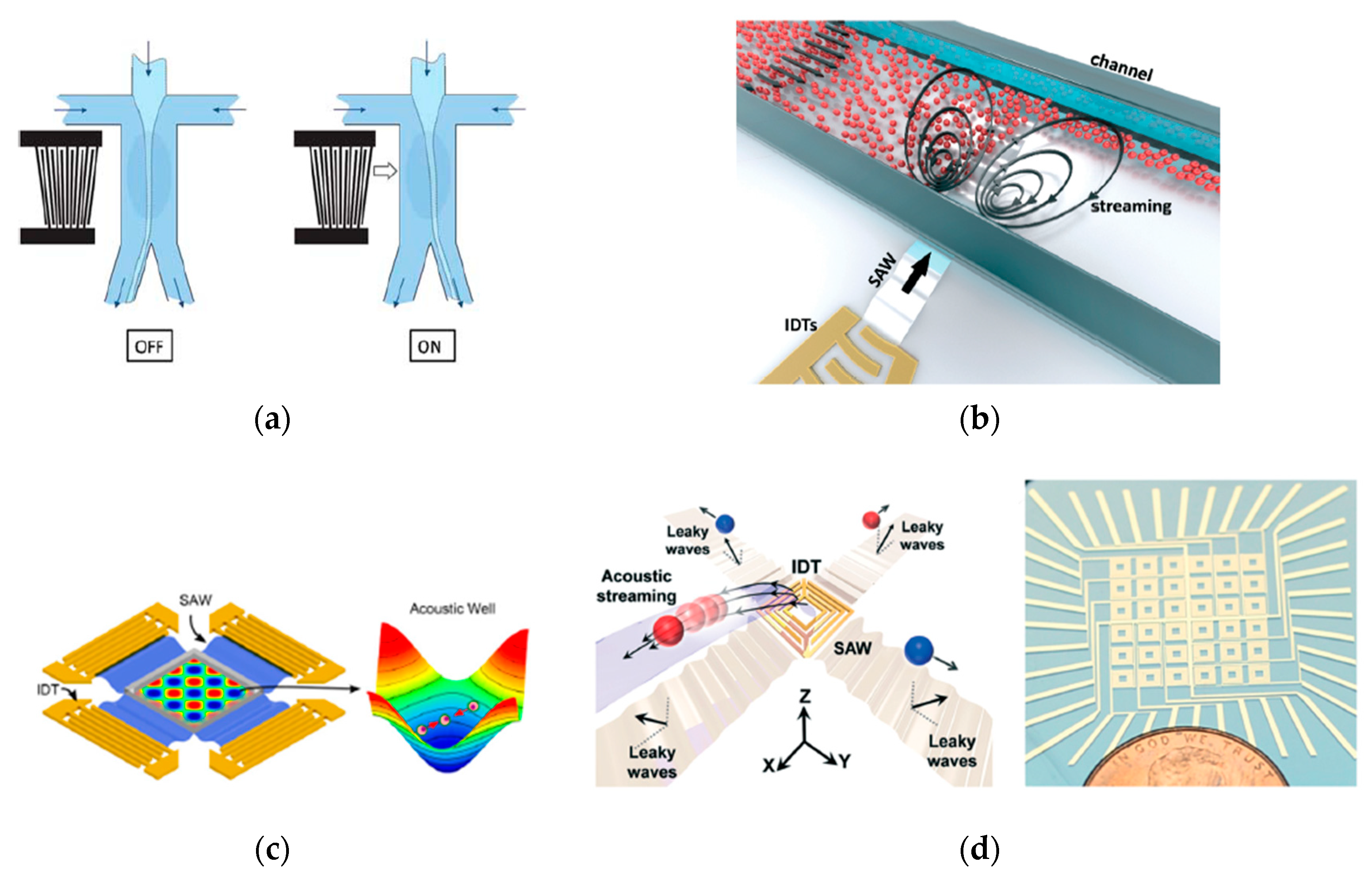
3.1. Manipulation by SAW

In-plane micromanipulation is the most prominent feature of SAW-based manipulation. Since surface acoustic waves always propagate along the surface, the manipulation of particles also occurs in the plane. The in-plane micromanipulation environment is usually a liquid-filled channel or chamber that can be integrated on a tiny silicon chip named lab on a chip. Figure 1a,b show the concept of in-planar manipulation. More examples are shown in Figure 2. According to the previous description, we classify these devices into TSAW and SSAW devices. We introduce the features and their relationships in the next two subsections. In-planar manipulating devices are generally operated in a manner that is dominated by ARFs, primarily to achieve transport, sorting, and patterning of large numbers of particles. Table 1 provides some research schemes of in-planar manipulating devices in recent years, where their information is introduced. The particle sizes are mostly on the micron and submicron scales, the driving frequency is larger than 1 MHz, and the power is usually low.

3.1.1. TSAW Devices

TSAW devices are the most common in-planar micromanipulation method, and have been maturely applied in microfluidic systems and lab-on-a-chip. Figure 1a shows the structure of a typical TSAW micromanipulation device. The acoustic potential gradient generated by a radiation force or streaming manipulating particles along its direction is a fundamental phenomenon for TSAW, and is vital for the sorting and transportation of particles or cells.
The method proposed by Franke et al. [16] in Figure 2a shows an earlier typical TSAW sorting device. Earlier studies could only use an acoustic field force to manipulate particles. The particles are carried into the channel by a jet. The Interdigital Transducer (IDT) switching can control the deflection direction of the jet to achieve particle sorting. Researchers must be careful to avoid the effects of acoustic streaming, scattering forces, and internal reflection in channels on the particles. This means that the efficiency of such particle sorting is not high enough because more accurate classification can be achieved only when the number of particles is limited and the passing speed is fast. As described in Section 2.1, particles with different particle sizes behave differently in the same acoustic field. Therefore, more efficient classification methods exist for distinguishing particles with different particle sizes.
As shown in Figure 2b, the TSAW-based in-plane manipulation scheme proposed by Collins et al. [45] is one of the most representative solutions in recent years. Different from previous similar schemes, the κ in this work was set to nearly 1 (actually κ   was   ~ 1.3 , which is the threshold between acoustic-streaming-dominant and scattering-forces-dominant) rather than κ 1 (linear-ARF-dominant). Although acoustic streaming and the scattering force show specific nonlinear characteristics at this ratio, rules must be followed at a specific position. At the very middle of the IDTs, the equation of motion of the particle can be simplified as [45]:
v middle ( x ) = A 0 ω e α x
where v(x) is the fluid displacement velocity in position x, A 0 is the initial substrate displacement (similar to the initial amplitude), ω is the angular frequency, α is the interface propagation attenuation between different media, and x indicates the position. The maximum vibration velocity is shown in Equation (7), which can be applied approximately in a nearby area where the acoustic field force can be described as:
F A = ρ β v middle 2 ( x )
where ρ is the fluid density and β is the velocity attenuation parameter in the fluid. Since such devices are oriented toward large particles and do not reduce the effects of acoustic streaming (and even emphasize this effect), these devices have limited influence on small particles and tend to perform better in particle sorting.
Although it is widely used in particle sorting, TSAW has other applications. Fakhfouri et al. [10] showed that the acoustic streaming produced by TSAW can make particles swirl and thus form patterns. Brenker et al. [23] and Sesen et al. [24] proposed droplet generation and droplet fusion methods, respectively, based on TSAW with similar equipment, verifying the effectiveness of TSAW in droplet operations.

3.1.2. SSAW Devices

The device shown in Figure 1b is another kind of in-plane manipulation method, a SSAW manipulating device, which places the IDTs symmetrically to create a stable SSAW field inside the chamber or channel, according to the review of Lin et al. [3]. The chamber or the channel should have a simple shape, which is typically has 1D properties. A simple setting method of the two-dimensional (2D) symmetrical distribution is shown in Figure 1b. The placement of the transducer can be designed according to other distributions, such as an annular array. Compared with the TSAW field described above, SSAW better manipulates large numbers of particles. Particles in the standing wave field are easily concentrated at the standing wave node (1D) or in the potential well (2D or 3D). This means that, in most cases, R p should be relatively much smaller than the wavelength, which satisfies the optimal operating conditions based on acoustic field forces. The devices based on SSAW have different operation modes. These systems can be driven by sinusoidal signals that require only a few volts of input voltage or less than 1 W of input power. Since the condition of resonance needs to be satisfied in a state where the system is stable, and the particle size, mentioned later, should have an additional limitation, the frequency of generating the ARF is approximately larger than 1 MHz (affected by the medium).
The use of SSAW equipment is difficult. The particle transport of SSAW requires constant changes in the position of the nodes or potential wells by changing the frequency or phase of the IDT, for which further optimization is required. Single SSAW devices create a static acoustic field, which means that the standing wave field has a fixed 1D shape. If the system has a low input damping, the resonant operation model can provide high efficiency in terms of force applied for given input power. However, if the system does not work in resonant conditions, higher input power may not be accompanied by higher output efficiency. Researchers have to design different resonant devices, which may be infinite but cannot be used in different conditions, to adapt to different applications. A solution was provided soon after people realized this problem. Researchers have tried to overcome the traditional method of operating in a chamber or channel, in other words, the resonant devices, but using a dynamic field.
By controlling the input frequency of the transducer, the distribution and strength of the acoustic field can be changed dynamically [41]. Compared to a static field, SSAW manipulation using a dynamic field is not limited to a simple switching operation. In contrast, the complexity and cost of dynamic field devices have also increased dramatically. A single dynamic device might be able to perform multiple functions, such as reconfiguration, oriented to multiple kinds or sizes of particles, which require multiple static acoustic field devices to complete. In general, dynamic fields can be generated using two methods: moving the transducer to change the focus or structures of the field and using a non-resonant device that sets the arrangement of the different transducers and their frequency and phase to change its Gor’Kov field. The non-resonant manipulation methods have a lower efficiency due to the existence of damping. The efficiency can be evaluated, according to Glynne-Jones et al. [40], by multiplying the efficiency of the corresponding resonance field by the reciprocal of a quality factor (Q factor). Q is strongly correlated with the damping generated by the system (material, medium, etc.).
The dynamic field manipulation devices proposed by Guo et al. [13,52] shown in Figure 2c have indicated the tendency of in-plane micromanipulation, which is the purpose of controlling particle motion by continuously changing the acoustic field. In this work, the transducers were set symmetrically and emitted acoustic waves with the same frequency, generating a 2D standing wave field in the middle chamber. The 2D standing wave field generates a potential well at the intersection of two sets of 1D standing wave nodes perpendicular to each other, where the particles are concentrated. When the particles need to be moved, the position of the nodes can be changed by changing the phase relationship of the standing wave field in the corresponding direction, thus changing the position of the particles. The acoustic streaming in the standing wave field is still ubiquitous in each potential well, so the particles located within it are continually making a rotating motion. However, particles in a single potential well cannot be operated independently. Thus, it is almost impossible to control multiple particles to move along different paths simultaneously using this device.
Both TSAW and SSAW devices are important branches of in-planar manipulation methods. TSAW is more conducive to particle transport and classification, whereas SSAW has better performance in particle patterning and precise translating. In terms of the driving frequency, particle size, input power, and operating object, no pronounced difference exists between them, as shown in Table 1. Both TSAW and SSAW share characteristic limitations. These two devices are applied only inside the plane, but do not provide control in the vertical direction. However, neither of these devices can control the movement of individual particles along different paths when there are a large number of particles in the acoustic field.
In recent years, new solutions have emerged that combine TSAW and SSAW. In the system proposed by Zhang et al. [50], the transducers are smaller units that can be controlled separately by the upper controller. In this work, the authors used the mixed effect of ARF and acoustic streaming in the water layer to push the floating object following the directions of SAW propagation. When a small transducer unit (referred to as a micro-pump) is activated, an upward jet is generated in the +z direction to suspend the particles. Simultaneously, a high acoustic field gradient is generated around the edges of this transducer, and leaky waves simultaneously occur. Under the combined effect of acoustic streaming and the leaky wave generated by the acoustic field gradient, particles can be pushed away from this micropump. As shown in Figure 2d, each of the unit IDTs in an array embedded beneath the carrier fluid serves as a micro-pump for fluids along the x and y axes. Therefore, an object can be programmed to move in predesigned routes following the sequential triggering of hydrodynamic gradients by selectively switching different unit IDTs on and off.

3.2. Manipulation by BAW

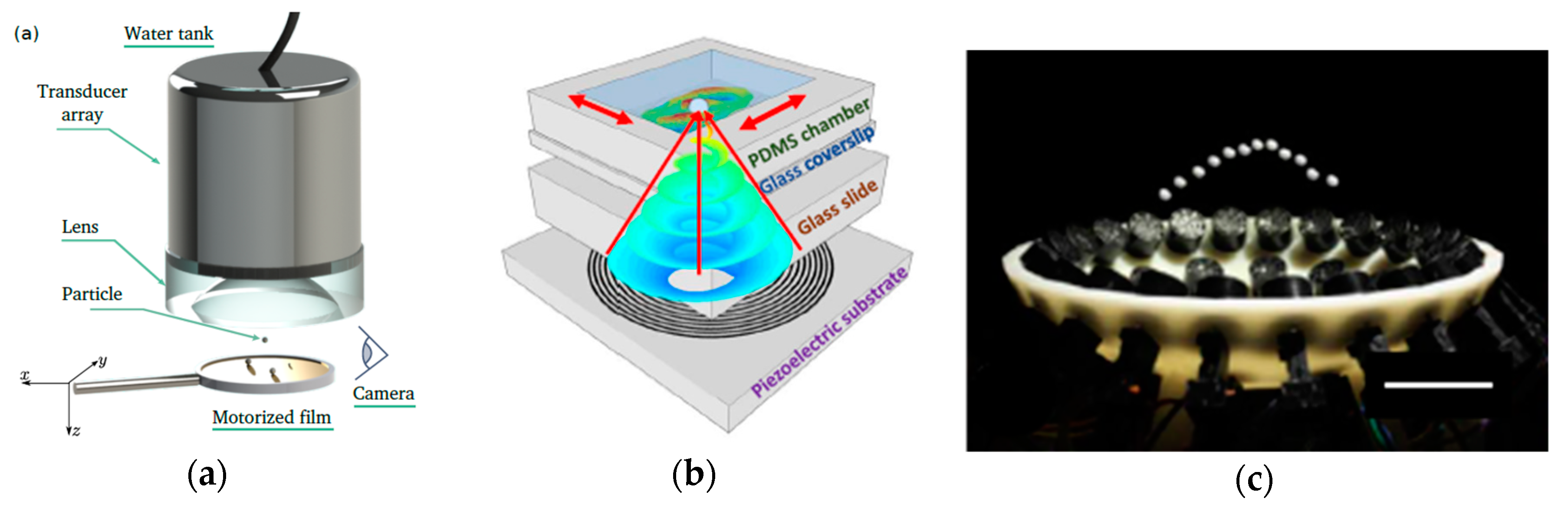
3.2.1. UTW Devices (Ultrasonic Acoustic Beam Tweezers)

As mentioned above, research on such devices is not popular, but some research programs are important. The most prominent feature of in-plane micromanipulation is that this system is suitable for manipulating a large number of particles or cells simultaneously, but cannot control a single particle without affecting the movement of the other particles. The acoustic beam manipulator driven by BAW (or UTW for detail) can compensate for this disadvantage. The ideal acoustic beam tweezers is depicted in Figure 1c.
Wu et al. [56] first proposed the concept of ultrasonic acoustic beam tweezers. They followed the idea of optical tweezers and experimentally explored using two counter-propagating focused acoustic beams from 3.5 MHz transducers. Although they trapped the latex particles successfully, no movement of the trapped particles was performed in their experiments. A variant on this simple beam device was reported by Yamakoshi et al., who trapped particles in a channel at the focus of two propagating acoustic beams driven out of phase, where the transducers were placed side by side. Lee et al. proved a single acoustic beam is able to trap particles like an optical beam if the particles are small enough and the acoustic field force is relatively large [19,57]. UTW devices have two manifestations: shear wave and longitudinal wave. This device can generate Bessel vortex in a cross-section. Similar to the sound field pattern in Figure 1c, particles can be trapped in the center of the sound field in the cross-section to achieve the manipulation effect.
Baresch et al. used a single beam to achieve three-dimensional (3D) control of particles, as shown in Figure 3a [58,59,60]. Acoustical beam tweezers can push, pull, and accurately control both the position and the forces exerted on a single particle. The broad spectrum of frequencies covered by coherent ultrasonic sources provides a wide variety of manipulation possibilities from macro- to microscopic-length scales. However, the array of equipment that produces the acoustic beam is too large, which is cumbersome to move and thus provides inflexible manipulation of particles. In response to this problem, Baudoin et al. proposed a simpler solution [18], as shown in Figure 3b. They unleashed the potential of focalized acoustical vortices by developing the first flat, compact, paired single electrode, and focalized acoustical tweezers. These tweezers rely upon spiraling transducers obtained by folding a spherical acoustical vortex on a flat piezoelectric substrate. The focused vortices acoustically trap in a small range, so produces better performance in the control of a single particle or cell. Due to the simplicity of the technology and its scalability to higher frequencies, this work opened possibilities of individual manipulation and in situ assemblies of physical and biological micro-objects. To strictly demonstrate the 3D trapping function with progressive waves, it is necessary to eliminate any stray standing waves that may occur due to wave reflections on the wall and thus should be performed in a large water tank to simulate free-space conditions.
The device shown in Figure 3c, which was proposed by Marzo et al. [61], is another kind of acoustic beam tweezer. The main idea is to levitate objects in the air through the acoustic beam generated by a BAW. This method has the advantages of optical tweezing (i.e., single-beam, rotation, holographic control, and multiple particles) with the efficiency and versatility of acoustic levitation, and could lead to the development of powerful tractor beams. Multiple acoustic beam manipulation units are evenly arranged on the arc surface and aligned with the center of the sphere. By changing the phase or switching the unit, different-shaped sound field potential wells are formed at the focal point to achieve operation. Particles can move and rotate in the potential field without moving the units. However, the size of the particles that can be manipulated by such equipment is usually large, and a large energy concentration is generated in the place of the operation area, so it may not be biocompatibile.

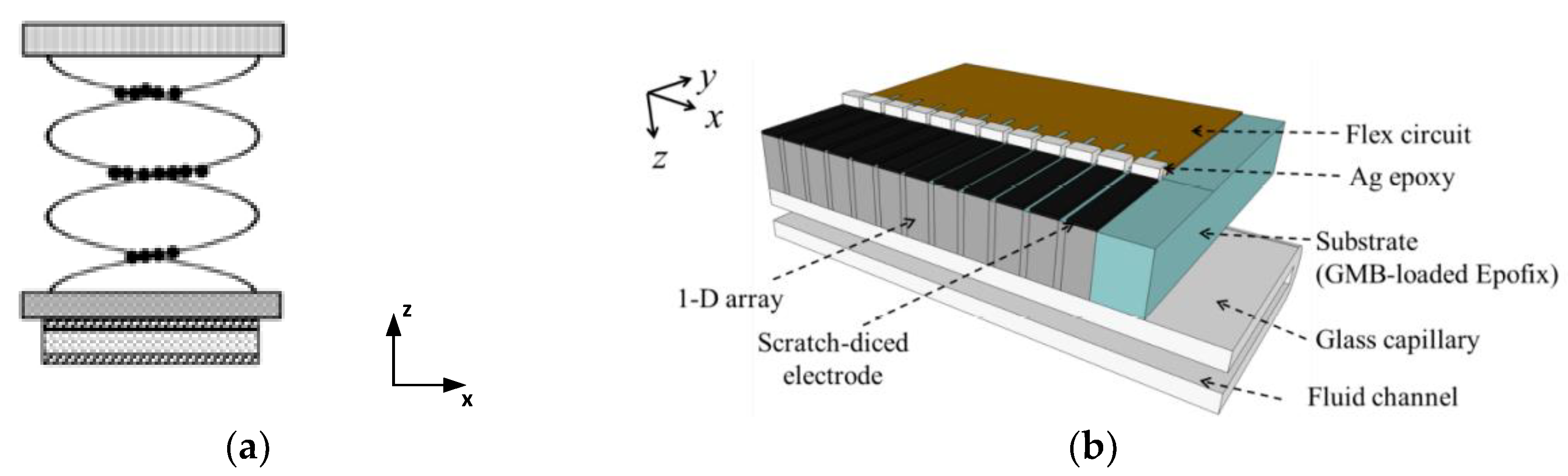
3.2.2. USW Devices (Ultrasonic Transducers Array)

The ultrasonic transducers array manipulating devices, as shown in Figure 1d, are also called ultrasonic standing wave (USW) devices. For a 1D USW device, the transducers are evenly arranged on the substrate in a specific direction, where silica reflector covers particle-manipulating channels. Therefore, a stable standing wave field can be generated in the longitudinal direction of the flow channel, achieving particle levitation (Figure 4). Since acoustic waves are transmitted inside the medium, this type of device belongs to the BAW category. With the orderly switching of the transducer array below, particles can move freely in the direction of the array arrangement, which is similar to the principle of a magnetic levitation train. Based on the same principle, Qiu et al. [27] expanded the array to a two-dimensional scale, constructing an operation method to control the movement of particles in 3D space. Related research is much older, such as the research of Kozuka et al. [15], but it is not particularly popular. This configuration is not innovative in mechanics. The aggregation and propagation of particles at the nodes produce a variety of effects using the ARFs, as mentioned above [14]. Many studies have not specifically emphasized the longitudinal movement of particles because it is easily achieved. Similar to the application of SSAW, the instantaneous change in the phase of the transducers can change the position of the standing wave node in the longitudinal direction, thereby controlling the movement of the particles in the longitudinal direction. Fushimi et al. [62] recently proposed a special hologram display device. A phased array of ultrasonic emitters was used to realize a volumetric acoustophoretic display in which a millimetric particle is held in mid-air using ARF and moved rapidly along a 3D path. Synchronously, a light source illuminates the particle with the target color at each 3D position. The response of the particle operation in this system is fast and the rendering speed can reach 10 Hz.
In general, USW devices have some of the advantages of in-plane manipulation, including easy establishment, easy control, and stable performance in particle cluster operation. USW devices extend the operation dimension of in-plane operation equipment. However, they have some limitations, mainly including the high driving frequency (~10 MHz) and high cost. This kind of equipment only performs well in the translation of particles or cells, and some complex movements still cannot be achieved.

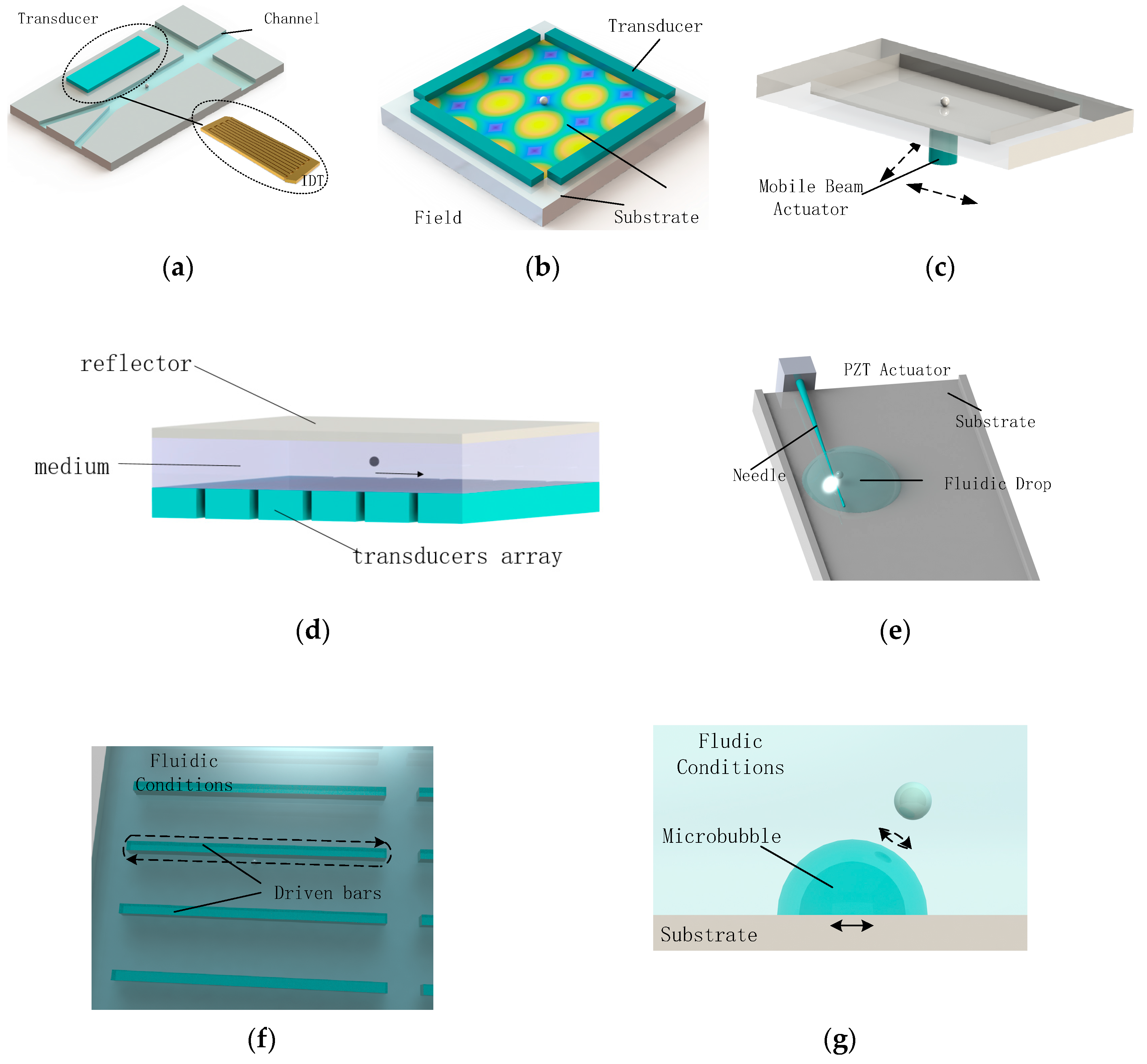
4. Micromanipulation by Vibration-Induced Steaming Flow

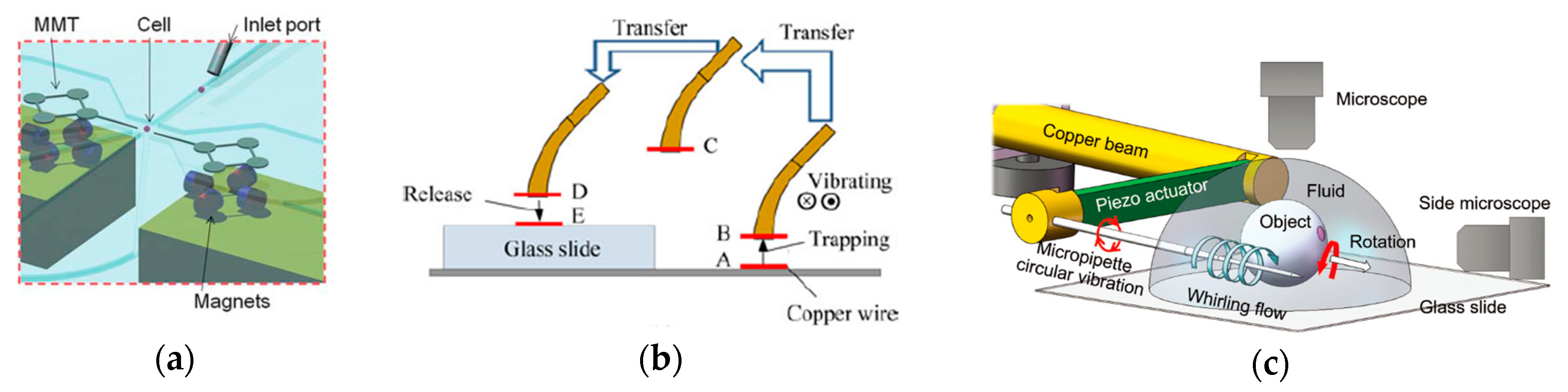
4.1. Vibrated Needles

Vibrated-needle-driven manipulation is another kind of popular method. A simple example of needle-driven micromanipulation is depicted in Figure 1e. Different from in-plane manipulation systems, needle-driven manipulation is more flexible and versatile. Different needle-driven manipulation methods differ in terms of needle shape, operating environment, oriented object, and principle. In general, the principle of needle-driven manipulation can be divided into two categories: inducing the flow of the surrounding fluid through the vibration of the tip, thereby driving the movement of the object in the fluid; and stimulating the acoustic streaming and radiation force, which we discussed in the previous session, in the vicinity of the tip through its high-frequency vibration. The term needle here refers to a generalized needle shape, which means an operating end with a large aspect ratio. The shape of the needle directly influences the manipulation effect, according to the Tang et al. [63]. Their results showed that the ultrasonic needle’s vibration generates the acoustic field, which aggregates materials at the micro or nano scales, and the ARF contributes little to the concentration. The elliptical, rectangular, and rhombic cross-sections of the needle were investigated as well. The needles with elliptical or rhombic cross-sections were found to perform better in concentrating ability than those with rectangular cross-sections.
The development of needle-driven micromanipulation started with contact operation. The tip did not vibrate but directly pushed the cell to move. The research Hagiwara et al. [64,65] is shown in Figure 5a, providing a typical example of contact operation. They presented a driving method for an on-chip robot, for which a piezoelectric ceramic is applied to induce ultrasonic vibration to the microfluidic chip. The tip and the base constitute a controllable miniature robot, which is actuated by permanent magnets in a microfluidic chip. The high-frequency vibration reduces the sufficient friction on the magnetically driven microtool (MMT) significantly, so the operation accuracy, output force, movement velocity, and execution efficiency were significantly improved. However, high-frequency vibration does not directly affect the manipulation of the robot on the cells, which is still a type of contact operation. The rotation of a single cell needs to be coordinated by the needle tips of two robots. This is troublesome, but due to the simple structure, the cost is still acceptable.
Although contact operation is low cost and high efficiency, microparticles, especially cells, are considerably influenced. Using vibration to stimulate fluids or acoustic field force to keep microparticles or cells from contacting the manipulating end is an alternative approach. In the early work of Hu et al. [68], they used high-frequency vibration to rotate tiny particles around the tip of a needle. In this work, the frequency of the tip vibration was determined by the mode of resonance; the frequency of vibration in a section of water was about 66.75 kHz. In other words, they used a method of exciting acoustic microstreaming near the tip to trap small particles. The streaming rotates the trapped particles near the tip. The viscosity of the liquid and the density of the particles determine the minimum driving sound pressure separately, which means that the effective range with the same power output is different for different types of particles or liquid media. In the process of rapid translation, the limiting force of acoustic pressure is not sufficient, so particles sometimes fall off. Enhancing the acoustic field is the most effective solution to this problem, so such devices are often inefficient. Some other studies used the high-frequency vibration of the tip to generate acoustic radiation to drive the movement of particles, such as Chen et al. [53], as shown in Figure 5b, who achieved in-air manipulation. A 40 μm diameter copper wire with a length of 1–14 mm can be trapped stably by ultrasound and transferred through any 3D path in the air by moving the transducer.
For special situations, such as cell manipulation, which needs a fluidic environment in most cases, flow can be generated by low-frequency vibration, called stirring. Compared to exciting an acoustic field in liquid, generating a micro-vortex directly through vibration is more efficient and natural. Liu et al. proposed a multifunctional noncontact micromanipulation system [28,29,67], as shown in Figure 5c. Resonance of a cantilever structure is used to extend the vertical vibration of a single piezo actuator to the 2D circular vibration of a micropipette. The circular vibration in fluids generates the whirling flow featured by low pressure in the core area and a flow velocity gradient. The low pressure can immobilize objects nearby and transport them together with the micropipette, and the flow velocity gradient is used to form a torque to rotate the immobilized object. The advantages of using the low-frequency oscillation (~350 Hz) method are that the low-frequency vibration mode is highly controllable, and such a low frequency easily achieved with a piezoelectric driver, and the cost is low. Although the method is versatile in the current practical application of micromanipulation, which is the operation of micron-sized cells in a liquid environment, it still has certain shortcomings. The microflow induced by low-frequency vibration is hard to control, especially for cell rotation. Such microflows have strict requirements for the medium, and the minimum scale of manipulation is also limited by the nature of the fluid, making it challenging to reach submicron or even nanoscale manipulations.
Compared with in-planar micromanipulation, needle-driven manipulation is more flexible when controlling a single particle and provides more motions. 3D operation is easy for needle-driven manipulation but difficult for the in-plane manipulation method. It avoids the complex mathematical models required for control and the many conditions that must be ignored when establishing the model. The transducers used in the in-plane systems are more expensive and experience more manufacturing difficulties, which pose barriers to practical implementation. Compared to the scheme using second-order sound pressure to generate microfluidics, probe vibration is more similar to the effect of agitation, so its action mode is simple. The vibration frequency requirements are much lower, and the non-contact operation mode makes it biocompatible. Therefore, the needle-driven micromanipulation system is relatively easy to control, inexpensive, and has potential for application in an open environment instead of chambers or channels. However, the in-plane operation method is better than the application of needle-point driving in the field of programming design and automatic control. The latter still needs to be performed by an operator, and experience is required. The control of the particles depends more on the operator’s observation, which means a certain difficulty in automatic control.

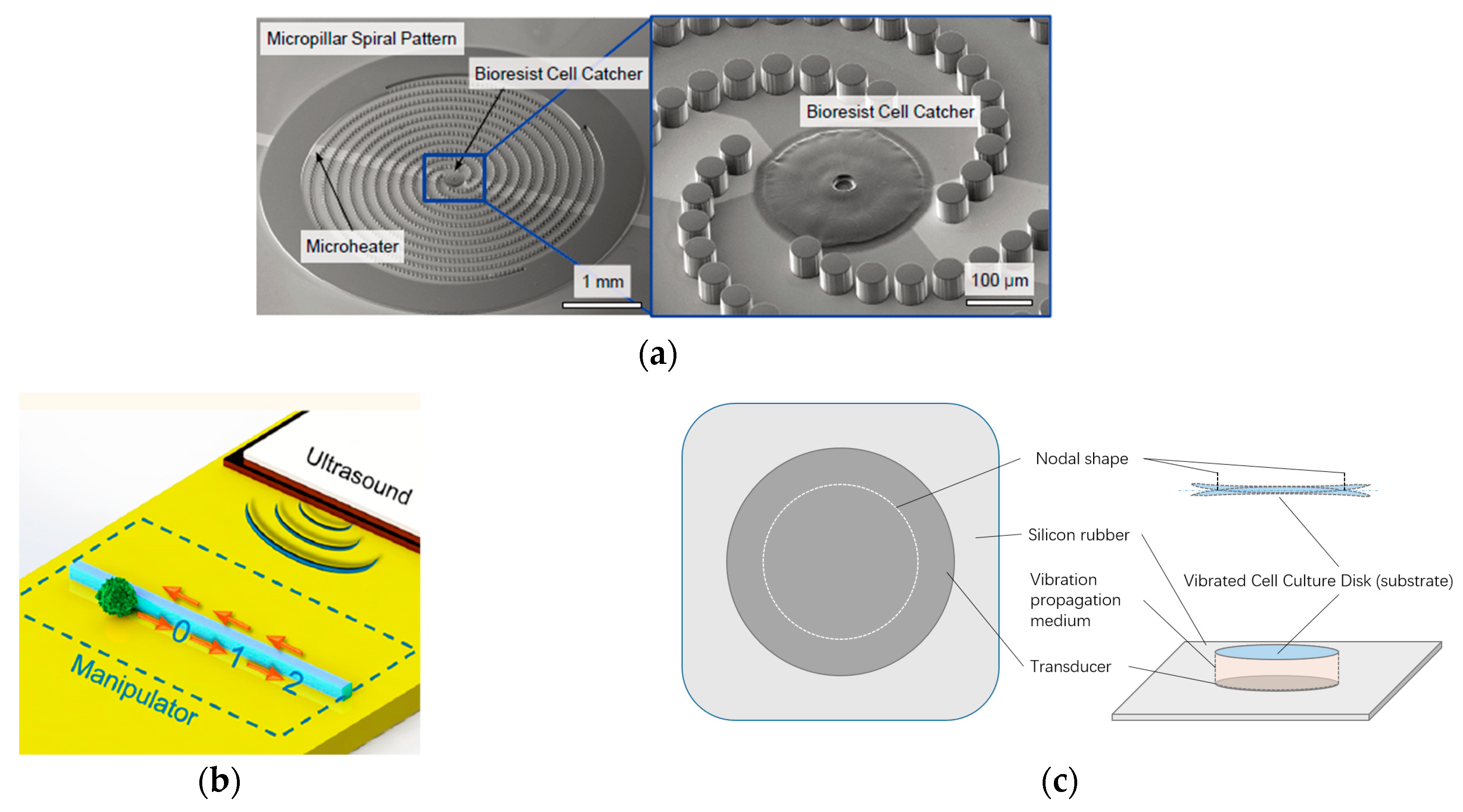
4.2. Vibrated Geometric Substrates

The vibrated geometric substrate (VGS) refers to the terminal performing the operation function being the substrate or being mounted on the substrate. This kind of manipulating device has a variety of shapes and structures. Figure 1f shows a typical substrate manipulating structure. Micromanipulation using a structure mounted on a substrate is suitable for many specific operational tasks. Micropillars, micro line-shaped strips, and special-shaped cavities are all common structures that expand upon the substrate. Although the VGS manipulator is similar to the general in-plane manipulating device in shape, the former is more inclined to use the vibration-induced phenomenon of fluid rather than ARF.
The VGS manipulator proposed by Hayakawa et al. [69,70] has a typical structure (Figure 6a). By applying a circular vibration to the spiral pattern of the micropillars array, a swirling flow is induced around the micropillars, and target particles or cells are transported toward the catcher placed at the center of the spiral. Li et al. [71] similarly used line-shape strips structures, which are illustrated in Figure 6b. High-frequency vibration induces strong turbulence at sharp corners of the strips, with linear flow near the long straight side. So, the particles around the strips can be driven in the linear region at a stable speed. Their acoustic robotic platform allows large-scale parallel transport for microparticles and cells along given paths. A human–microrobot interface was designed that enables the manipulator to respond promptly to the users’ command inputs for accurate transport. The two methods above can be applied to cell transport. The lower operating frequency (<1 MHz), simpler operation mode, and potential programmability have certain advantages for application. However, its particular structure requires complex manufacturing processes and limited execution capabilities. Every proposed new structure oriented to the operation target has to do all the work from beginning to end.
Using silicon substrate vibration to control particle motion is another method. The vibration generated or propagated through the substrate can induce the ARF. This effect can be observed in the vibration of the drumhead. Imashiro et al. [72,73] proposed a manipulator where a vibrating glass substrate was used. Cells amass along with the node of resonance vibration when the vibration is excited on the substrate, since with the resonance vibration, the antinode position largely vibrates while the node position does not. The concept is schematically illustrated in Figure 6c. This resonance-based device is effortless in patterning, but not flexible enough and hard to apply. The related research is also less popular, but provides significant inspiration for directly exciting the vibration on the glass substrate, which significantly reduces the complexity of transducer production.

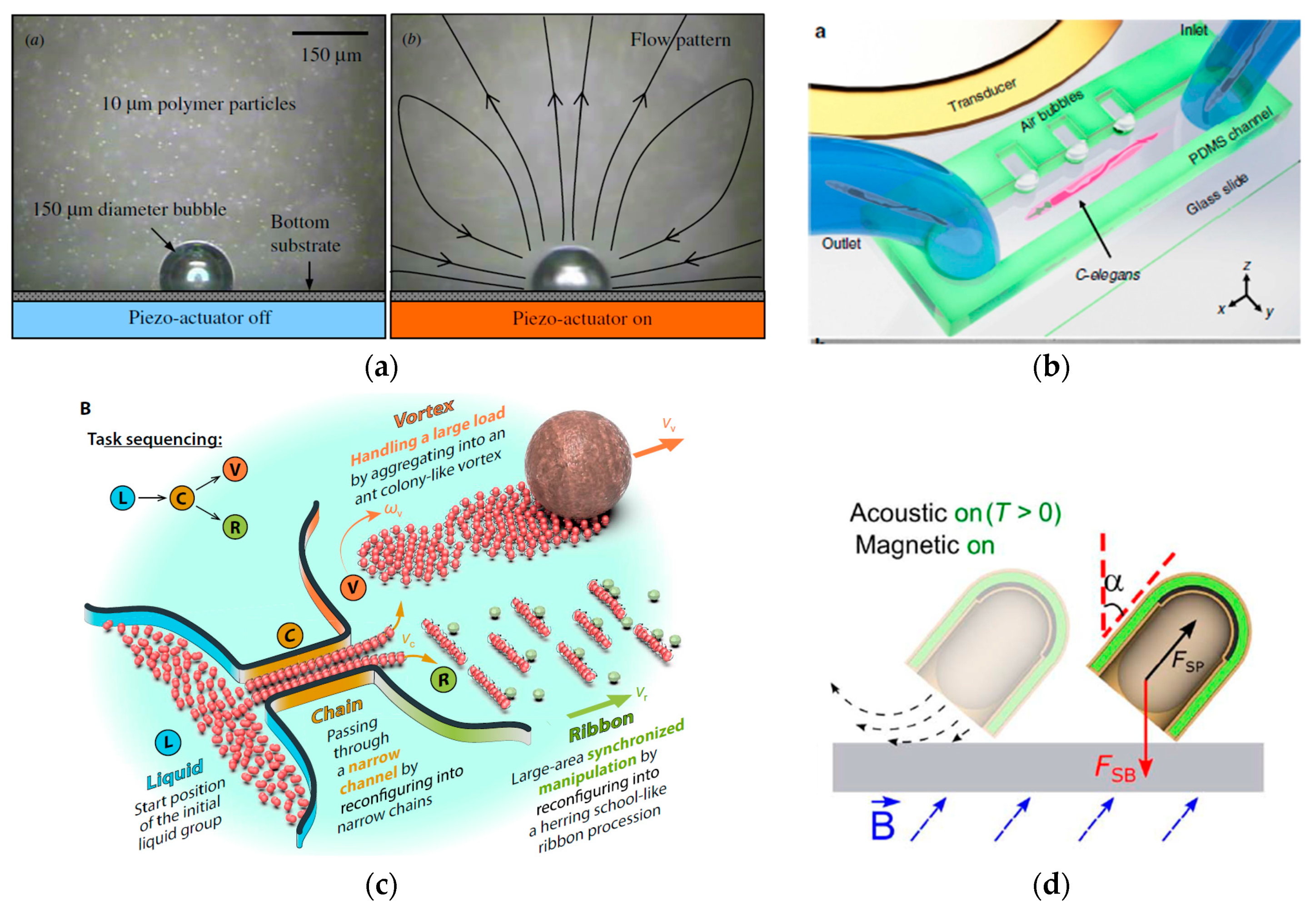
4.3. Vibrated Microbubbles and Microrobots

Micromanipulation with microbubbles or microrobots is an old idea that was not important until the more recent development of manufacturing technology. With both microbubbles and microrobots, the particles can be manipulated by controlling the vibration and movement of single or multiple microelements in operating space. The manipulation of microbubbles and microrobots is no longer limited to acoustic driving. Optical tweezers, electrophoresis, and magnetic tweezers are also effective methods. Microbubbles and robots can further manipulate other particles using the vibrations generated during the operation. Although this method is intuitively cumbersome, it is flexible, efficient, and highly biocompatible for cell manipulation in a fluid field.
Manipulation by microbubbles is a useful method. Although a single stable bubble can generate a fragile flow due to its spontaneous vibration, almost no significant effects are provided for control. Controllable-bubble-based microfluid can be generated by controlled vibration like SAW or a piezo actuator, regular collapse by a high-frequency laser pulse, or acoustic cavitation. In particular, several bubbles that are close to each other and in a vibrating state can produce more complex mechanical phenomena that can be partially solved by applying Bjerknes’ circulation theorem. Some related studies were published about the stream around multiple bubbles, such Mobadersany et al. [33], and the influence of stream on bubbles, such as Combriat et al. [35]. The microrobot system proposed by Ren et al. showed the potential of Bjerknes force in the field of acoustic manipulation. However, micromanipulation using forces among multiple bubbles requires considerable research. A simple microbubble manipulating model is shown in Figure 1g. Many methods for generating microbubbles are possible. Using a laser pulse to irradiate the substrate and then convert into heat to generate vapor microbubbles is universal [36,74,75,76]. Due to the pulse of light and the instability of vapor, the bubbles collapse periodically, resulting in cavitation in a small range. The original intention of this design was to avoid direct damage to the cells caused by optical tweezers, but the idea of using microbubble vibration and cavitation to control the cells has inspired microbubble manipulators. Photothermally excited bubbles respond quickly and the exciting bubbles can move quickly in the plane. Therefore, a two-dimensional movement of microbubble-driven particles in a channel or a chamber can be achieved according to the method above.
Generate bubbles using the photothermal effect or other methods such as acoustic cavitation and chemical catalysis is difficult. Inject bubbles into the flow channel directly to make them adhere to the substrate is a more convenient option, as conducted by Chung et al. [31] (Figure 7a). In their work, the piezo-actuator oscillated the gaseous bubble so that current flows were generated around the bubble, and then the neighboring objects are captured in and orbiting in the current flows. The electrowetting-on-dielectric actuation was used in the meantime to move the bubble following the preset direction. The piezo-actuator remained open during the movement of the bubble so that the captured object would not fall off. Glass particles, fish eggs, and even live daphnia can be captured in this system (1.5 mm diameter bubbles, 4.5–15kHz drive frequency, 400 V drive voltage to piezoelectric actuators, and voltage of 80 V at 1 kHz are applied for electrowetting-on-dielectric actuation). Another simple method of bubble generation is designing a special cavity so that when liquid enters the channel, bubbles can be automatically formed or captured in it [77,78]. As shown in Figure 7b, the channel contains linear arrays of rectangular microcavities where microbubbles will be trapped due to the residual gas pressure when the liquid is injected. Although the bubbles cannot move at will, their array can generate microfluidics in the flow channel through the vibration excited by the acoustic piezo-actuator, thereby driving the particles (Caenorhabditis elegans in their work) to move.
Some microrobots also use a method similar to microbubbles to manipulate particles through their vibrations [79,80]. Many microrobots are a kind of particle, and also urgently requiring micromanipulation. However, compared with some objects sensitive to manipulating methods such as cells, these microrobots have stronger adaptability. Therefore, this compromise method to achieve cell translation, rotation, etc. is also feasible. In addition, microrobots have strong scalability. A robot cluster composed of multiple microrobot units can be regarded as an individual, which can enable the precise control of a single cell in a large field. Figure 7c depicts the research of Xie et al. [81,82]. A microparticle can be transported using three methods of manipulation, achieved through microrobot rotation and vibration, including pushing, steering, or pulling. Compared with microbubbles, microrobots are more stable and their mechanical properties are more prominent, but their manufacturing costs are higher and their use involves some difficulties. Some schemes combine microbubbles and microrobots, such as Ren et al. [83] (Figure 7d). A microbubble was enclosed in a semi-capsule-shaped robot, and the secondary Bjerknes force formed between the bubble and the actuator was used to drive the microrobot motion.
Figure 7. Vibrated microbubble and microrobot methods by Chung et al. [31], Ahmed et al. [77,78], Xie et al. [81,82], and Ren et al. [83]. (a) Particles are manipulated by an individual bubble, in which vibration is actuated by piezo-actuator or heat. (Republished with permission of IOP Publishing Ltd from reference [31]. Copyright © IOP Publishing Ltd; permission conveyed through Copyright Clearance Center, Inc.) (b) Particles are manipulated by bubbles trapped in channel caves; the vibration is usually actuated by SAWs. (Republished with permission of The American Association for the Advancement of Science from reference [77]. Copyright © 2019, The American Association for the Advancement of Science; permission conveyed through Copyright Clearance Center, Inc.) (c) A kind of microrobot that can catch and release particles by micro steam from their self-rotation or vibration. (Republished with permission of John Wiley and Sons from reference [82]. Copyright © 2019, John Wiley and Sons; permission conveyed through Copyright Clearance Center, Inc.) (d) A typical example of fusion among bubbles, microrobots, magnetic fields, and acoustic waves. (This figure is republished reference [83] of Ren et al. and licensed under CC BY 4.0. Copyright © 2019, The Authors)
Applsci 10 01260 g007
The reason why microbubbles and microrobots are classified into one category is that they both perform secondary micromanipulation, which means that their motion requires manipulation, and their motion characteristics drive the micromanipulation for other particles. This mode of manipulation is gentle enough for particles, especially cells that are not easily manipulated directly by other external forces. However, with the current level of technology, the result produced of this method is not perfect, the control cost is high, and the efficiency is very low. This field has more significance in research than in practical applications.

5. Discussion and Future Prospects

Although manipulation actuated by vibration-induced acoustic waves and streaming flow is not a new concept, much remains to be researched. Simple in-plane micro-manipulating devices have been extensively applied in the range of lab-on-a-chip scenarios, which is an important research interest in the related fields of vibration or acoustic micromanipulation. Due to better biocompatibility and lower cost than optical tweezers, it has gradually become universally applied in the field of cell micromanipulation. Magnetic tweezers are relatively common biological manipulation methods, but since most cells are not magnetic, directly manipulating cells with magnetic tweezers is challenging. For easy control, the current VAW devices, especially the in-plane manipulating devices, have restrictions on the shape but not the material of particles, which are different from restrictions on magnetic tweezers. Therefore, in the future, when acoustic tweezers can accurately manipulate irregularly shaped particles, they could replace magnetic tweezers to a certain extent. However, acoustic waves, as a kind of mechanical vibration performance, have strict requirements on the medium (a frequency of 200 MHz in water corresponds to a wavelength of 5 microns). The speed of mechanical wave propagation also affects the flexibility, accuracy, and response speed of acoustic micromanipulation.
Performance improvement is the primary trend in the development of acoustic micromanipulation. More sophisticated control strategies may emerge and lead to even more versatile manipulation capabilities. One possible approach is to cast the manipulation challenge as an optimization problem. The operation precision problem could be considered as an optimization project [41,84]. The theoretical basis of acoustic operation is unstable. The mathematical model we use for analysis is too simplified sometimes, which prevents obtaining ideal results by directly estimating the particle control model and motion model. The optimization problem could reduce the impact of this model’s inaccuracy to some extent. In the future, machine learning, a tool based on optimization methods, could be used to predict the motion of particles and control.
The working scale of micromanipulators is a challenging issue, especially for in-plane devices, array devices, and beam devices. In the discussion of in-plane devices in this paper, we explained that the same acoustic wave has different effects on particles of different sizes, which is also applicable to other SAW and BAW devices. This phenomenon implies that fixed-frequency devices cannot achieve the same result for particles of various sizes. Chirped IDTs have been used to change the frequency and phase to control particles of different scales [51]. However, the layout of the transducer also affects the results, so this kind of device is only versatile within a small range. The acoustic manipulating devices have a substantial limitation in operating below 1 μm. The natures of fluids and mechanical waves vary significantly on microscopic scales (especially nanoscale), which is an important factor limiting the minimum scale of acoustic manipulation.
Combining acoustic manipulation with the another method is a solution to the problems above. Large amounts of related work have been published per the review by Glynne-Jones et al. [85]. Because different operating methods have different applicable scales, combining two different methods provides a broader manipulating scale and more flexible performance. Take the work of Tang et al. for example [86]. They combined acoustic transport and photochemical reaction to design an acoustic nanomotor. Compared with a single acoustic field, this method not only moves more flexibly and quickly but also provides a braking function. The fusion between the different acoustic operating modes described in that paper is also an attractive idea. For example, the beam device and the 2D in-plane device can be easily combined. As such, not only the simultaneous manipulation of multiple particles but also the operation of a single particle in a particle swarm can be achieved. In addition, microbubble and microrobot are typical results of multiple manipulation combinations. The size of microrobots manipulated by other methods is fixed, by which particles with different sizes can be transported.
There is additional potential for microrobots in VSF devices. Simple movements or handling tasks are not all that microrobots can achieve. Due to its small size, microrobots have broader application prospects in the fields of medical detection, diagnosis, treatment, and drug delivery. Self-assembly and cluster operation of microrobots were also attractive research areas in recent years. In this process, VSF is not only a useful tool in the process of microassembly but also the most direct means for the assembled microrobot to move. The efficient manipulation of particles with different shapes, control of the sound pressure level, and programmable operation in the microscale and even visual servo are important issues in this process. These issues have been hot topics in the research of VSF devices in recent years.

6. Conclusions

This paper provides an overview of the recent advances of micromanipulation by VAW and VSF devices. VAW devices are more suitable for the simultaneous manipulation of a large number of particles for cluster operations, such as particle classification and patterning, which are common in laboratory-on-chip applications. They require an actuator or transducer with high frequency (>1 MHz), the manufacturing process could be cumbersome in many cases, and the application target size is definite due to the resonance-based operating mode. However, VSF devices are suitable for independent 3D manipulation of a single or a few particles or cells, whereas it is inconvenient for cluster operations. These devices do not need a very high-frequency actuator or the strict requirement for particle size and working space (except the medium). A robust reconfigurable system with shallow driven frequency (<1 kHz) can simultaneously perform multiple operations such as particle trapping, transport, and rotation. Although its external drive components are usually large and are difficult to integrate into small chips, it is suitable as an external operator. Given the many existing problems, we tried to provide some of the prospects for vibration-actuated manipulations. Besides the fundamental improvement in control performance and accuracy, the conversion from control problems into optimization problems, the integration of vibroacoustic and other micromanipulation methods, and the application of vibration microrobots are suggested future development trends for vibration-actuated manipulations.

Author Contributions

Z.C. and X.L. drafted the manuscript; Q.H. and T.A. provided advice for the review and modified the manuscript; M.K. provided suggestions on the organization of the contents. All authors have read and agreed to the published version of the manuscript.

Acknowledgments

This work was supported by the National Natural Science Foundation of China under Grants (61873037, 61903039), China Postdoctoral Science Foundation (BX20190035) and the Grant-in-Aid for Scientific Research (19H02093) from the Ministry of Education, Culture, Sports, Science and Technology of Japan.

Conflicts of Interest

The authors declare no conflict of interest.

References

  1. Ashkin, A.; Dziedzic, J.M.; Bjorkholm, J.E.; Chu, S. Observation of a single-beam gradient force optical trap for dielectric particles. Opt. Lett. 1986, 11, 288–290. [Google Scholar] [CrossRef] [PubMed] [Green Version]
  2. Rasmussen, M.B.; Oddershede, L.; Siegumfeldt, H. Optical Tweezers Cause Physiological Damage to Escherichia coli and Listeria Bacteria. Appl. Environ. Microbiol. 2008, 74, 2441–2446. [Google Scholar] [CrossRef] [PubMed] [Green Version]
  3. Lin, S.-C.S.; Mao, X.; Huang, T.J. Surface acoustic wave (SAW) acoustophoresis: now and beyond. Lab on a Chip 2012, 12, 2766–2770. [Google Scholar] [CrossRef] [PubMed]
  4. Alexey, S.; Aranson, I.S. Magnetic manipulation of self-assembled colloidal asters. Nature Mater. 2011, 10, 698–703. [Google Scholar] [CrossRef]
  5. Gascoyne, P.R.C.; Wang, W.; Huang, Y.; Becker, F.F. Dielectrophoretic separation of cancer cells from blood. In Proceedings of the IAS ’95. Conference Record of the 1995 IEEE Industry Applications Conference Thirtieth IAS Annual Meeting, Orlando, FL, USA, 8–12 October 1995; Volume 1362, pp. 1366–1373. [Google Scholar]
  6. Ohta, A.; Chiou, P.-Y.; Han, T.; Liao, J.; Bhardwaj, U.; McCabe, E.; Yu, F.; Sun, R.; Wu, M. Dynamic Cell and Microparticle Control via Optoelectronic Tweezers. Microelectromech. Syst. J. 2007, 169, 491–499. [Google Scholar] [CrossRef]
  7. Marzo, A.; Drinkwater, B.W. Holographic acoustic tweezers. Proc. Nat. Acad. Sci. 2019, 116, 84–89. [Google Scholar] [CrossRef] [Green Version]
  8. Neuman, K.C.; Lionnet, T.; Allemand, J.-F. Single-Molecule Micromanipulation Techniques. Ann. Rev. Mater. Res. 2007, 37, 33–67. [Google Scholar] [CrossRef]
  9. Shi, C.; Luu, D.K.; Yang, Q.; Liu, J.; Chen, J.; Ru, C.; Xie, S.; Luo, J.; Ge, J.; Sun, Y. Recent advances in nanorobotic manipulation inside scanning electron microscopes. Microsyst. Nanoeng. 2016, 2, 16024. [Google Scholar] [CrossRef] [Green Version]
  10. Fakhfouri, A.; Devendran, C.; Ahmed, A.; Soria, J.; Neild, A. The size dependant behaviour of particles driven by a travelling surface acoustic wave (TSAW). Lab on a Chip 2018, 18, 3926–3938. [Google Scholar] [CrossRef]
  11. Beyer, R.T. Radiation pressure—the history of mislabeled tensor. J. Acoust. Soc. Am. 1976, 60, S21. [Google Scholar] [CrossRef] [Green Version]
  12. Lighthill, S.J. Acoustic streaming. J. Sound Vib. 1978, 61, 391–418. [Google Scholar] [CrossRef]
  13. Guo, F.; Li, P.; French, J.B.; Mao, Z.; Zhao, H.; Li, S.; Nama, N.; Fick, J.R.; Benkovic, S.J.; Huang, T.J. Controlling cell–cell interactions using surface acoustic waves. Proc. Nat. Acad. Sci. 2015, 112, 43–48. [Google Scholar] [CrossRef] [PubMed] [Green Version]
  14. Qiu, Y.; Wang, H.; Demore, C.E.M.; Hughes, D.A.; Glynne-Jones, P.; Gebhardt, S.; Bolhovitins, A.; Poltarjonoks, R.; Weijer, K.; Schönecker, A.; et al. Acoustic Devices for Particle and Cell Manipulation and Sensing. Sensors 2014, 14, 14806–14838. [Google Scholar] [CrossRef] [PubMed] [Green Version]
  15. Kozuka, T.; Tuziuti, T.; Mitome, H.; Fukuda, T. Acoustic micromanipulation using a multi-electrode transducer. In Proceedings of the MHS’96 Proceedings of the Seventh International Symposium on Micro Machine and Human Science, Nagoya, Japan, 2–4 October 1996; pp. 163–170. [Google Scholar]
  16. Franke, T.; Braunmüller, S.; Schmid, L.; Wixforth, A.; Weitz, D.A. Surface acoustic wave actuated cell sorting (SAWACS). Lab on a Chip 2010, 10, 789–794. [Google Scholar] [CrossRef] [PubMed]
  17. Fakhfouri, A.; Devendran, C.; Collins, D.J.; Ai, Y.; Neild, A. Virtual membrane for filtration of particles using surface acoustic waves (SAW). Lab on a Chip 2016, 16, 3515–3523. [Google Scholar] [CrossRef] [PubMed]
  18. Baudoin, M.; Gerbedoen, J.-C.; Riaud, A.; Matar, O.B.; Smagin, N.; Thomas, J.-L. Folding a focalized acoustical vortex on a flat holographic transducer: Miniaturized selective acoustical tweezers. Sci. Adv. 2019, 5, eaav1967. [Google Scholar] [CrossRef] [PubMed] [Green Version]
  19. Lee, J.; Teh, S.-Y.; Lee, A.; Kim, H.H.; Lee, C.; Shung, K.K. Single beam acoustic trapping. Appl. Phys. Lett. 2009, 95, 073701. [Google Scholar] [CrossRef] [Green Version]
  20. Valverde, J.M. Pattern-formation under acoustic driving forces. Contemp. Phys. 2015, 56, 338–358. [Google Scholar] [CrossRef]
  21. Collins, D.J.; Morahan, B.; Garcia-Bustos, J.; Doerig, C.; Plebanski, M.; Neild, A. Two-dimensional single-cell patterning with one cell per well driven by surface acoustic waves. Nat. Commun. 2015, 6, 8686. [Google Scholar] [CrossRef] [Green Version]
  22. Caleap, M.; Drinkwater, B.W. Acoustically trapped colloidal crystals that are reconfigurable in real time. Proc. Nat. Acad. Sci. 2014, 111, 6226–6230. [Google Scholar] [CrossRef] [Green Version]
  23. Brenker, J.C.; Collins, D.J.; Van Phan, H.; Alan, T.; Neild, A. On-chip droplet production regimes using surface acoustic waves. Lab on a Chip 2016, 16, 1675–1683. [Google Scholar] [CrossRef] [PubMed]
  24. Sesen, M.; Alan, T.; Neild, A. Microfluidic on-demand droplet merging using surface acoustic waves. Lab on a Chip 2014, 14, 3325–3333. [Google Scholar] [CrossRef] [PubMed]
  25. Hahn, P.; Leibacher, I.; Baasch, T.; Dual, J. Numerical simulation of acoustofluidic manipulation by radiation forces and acoustic streaming for complex particles. Lab on a Chip 2015, 15, 4302–4313. [Google Scholar] [CrossRef] [PubMed]
  26. Glynne-Jones, P.; Demore, C.E.M.; Ye, C.; Qiu, Y.; Cochran, S.; Hill, M. Array-controlled ultrasonic manipulation of particles in planar acoustic resonator. IEEE Trans. Ultrason. Ferroelectr. Freq. Control 2012, 59, 1258–1266. [Google Scholar] [CrossRef]
  27. Qiu, Y.; Wang, H.; Gebhardt, S.; Bolhovitins, A.; Démoré, C.E.M.; Schönecker, A.; Cochran, S. Screen-printed ultrasonic 2-D matrix array transducers for microparticle manipulation. Ultrasonics 2015, 62, 136–146. [Google Scholar] [CrossRef]
  28. Liu, X.; Shi, Q.; Lin, Y.; Kojima, M.; Mae, Y.; Fukuda, T.; Huang, Q.; Arai, T. Multifunctional Noncontact Micromanipulation Using Whirling Flow Generated by Vibrating a Single Piezo Actuator. Small 2019, 15, 1804421. [Google Scholar] [CrossRef]
  29. Liu, X.; Shi, Q.; Kojima, M.; Wang, H.; Sun, T.; Mae, Y.; Huang, Q.; Arai, T.; Fukuda, T. Non-contact high-speed rotation of micro targets by vibration of single piezoelectric actuator. In Proceedings of the 2016 IEEE International Conference on Robotics and Biomimetics (ROBIO), Qingdao, China, 3–7 December 2016; pp. 1564–1569. [Google Scholar]
  30. Li, N.; Hu, J.; Li, H.; Bhuyan, S.; Zhou, Y. Mobile acoustic streaming based trapping and 3-dimensional transfer of a single nanowire. Appl. Phys. Lett. 2012, 101, 093113. [Google Scholar] [CrossRef]
  31. Chung, S.K.; Cho, S.K. On-chip manipulation of objects using mobile oscillating bubbles. J. Micromech. Microeng. 2008, 18, 125024. [Google Scholar] [CrossRef]
  32. Lutz, B.R.; Chen, J.; Schwartz, D.T. Microfluidics without microfabrication. Proc. Nat. Acad. Sci. 2003, 100, 4395–4398. [Google Scholar] [CrossRef] [Green Version]
  33. Mobadersany, N.; Sarkar, K. Acoustic microstreaming near a plane wall due to a pulsating free or coated bubble: velocity, vorticity and closed streamlines. J. Fluid Mech. 2019, 875, 781–806. [Google Scholar] [CrossRef] [Green Version]
  34. Tho, P.; Manasseh, R.; Ooi, A. Cavitation microstreaming patterns in single and multiple bubble systems. J. Fluid Mech. 2007, 576, 191–233. [Google Scholar] [CrossRef]
  35. Combriat, T.; Mekki-Berrada, F.; Thibault, P.; Marmottant, P. Trapping and exclusion zones in complex streaming patterns around a large assembly of microuidic bubbles under ultrasound. Phys. Rev. Fluids 2018, 3. [Google Scholar] [CrossRef] [Green Version]
  36. Xie, Y.; Zhao, C. An optothermally generated surface bubble and its applications. Nanoscale 2017, 9, 6622–6631. [Google Scholar] [CrossRef]
  37. Lord Rayleigh, J.W.S.I. On the circulation of air observed in Kundt’s tubes, and on some allied acoustical problems. Philos. Trans. Royal Soc. London 1884, 175, 1–21. [Google Scholar] [CrossRef]
  38. Lord Rayleigh, J.W.S., IX. On the compressibility of gases between one atmosphere and half an atmosphere of pressure. Philos. Trans. R. Soc. London Series A Contain. Papers A Math. Phys. Character 1905, 204, 351–372. [Google Scholar] [CrossRef] [Green Version]
  39. Gor’kov, L. On the Forces Acting on a Small Particle in an Acoustic Field in an Ideal Fluid. Soviet Phys. Doklady 1962, 6, 773. [Google Scholar]
  40. Glynne-Jones, P.; Boltryk, R.J.; Hill, M. Chapter 7 Modelling and Applications of Planar Resonant Devices for Acoustic Particle Manipulation. In Microscale Acoustofluidics; The Royal Society of Chemistry: Cambridge, UK, 2015; pp. 127–147. [Google Scholar]
  41. Drinkwater, B.W. Dynamic-field devices for the ultrasonic manipulation of microparticles. Lab on a Chip 2016, 16, 2360–2375. [Google Scholar] [CrossRef] [Green Version]
  42. Skowronek, V.; Rambach, R.W.; Schmid, L.; Haase, K.; Franke, T. Particle Deflection in a Poly(dimethylsiloxane) Microchannel Using a Propagating Surface Acoustic Wave: Size and Frequency Dependence. Anal. Chem. 2013, 85, 9955–9959. [Google Scholar] [CrossRef]
  43. Hasegawa, T.; Hino, Y.; Annou, A.; Noda, H.; Kato, M.; Inoue, N. Acoustic radiation pressure acting on spherical and cylindrical shells. J. Acoust. Soc. Am. 1993, 93, 154–161. [Google Scholar] [CrossRef]
  44. Hasegawa, T.; Yosioka, K. Acoustic-Radiation Force on a Solid Elastic Sphere. J. Acoust. Soc. Am. 1969, 46, 1139–1143. [Google Scholar] [CrossRef]
  45. Collins, D.J.; Ma, Z.; Han, J.; Ai, Y. Continuous micro-vortex-based nanoparticle manipulation via focused surface acoustic waves. Lab on a Chip 2017, 17, 91–103. [Google Scholar] [CrossRef] [PubMed]
  46. Gendelman, O.V.; Vakakis, A.F. Introduction to a topical issue ‘nonlinear energy transfer in dynamical and acoustical Systems’. Philos. Trans. A 2018, 376, 20170129. [Google Scholar] [CrossRef] [PubMed] [Green Version]
  47. Erbaş, A.; Podgornik, R.; R Netz, R. Viscous compressible hydrodynamics at planes, spheres and cylinders with finite surface slip. Eur. Phys. J. E Soft Matter. 2010, 32, 147–164. [Google Scholar] [CrossRef]
  48. Manor, O.; Rezk, A.R.; Friend, J.R.; Yeo, L.Y. Dynamics of liquid films exposed to high-frequency surface vibration. Phys. Rev. E 2015, 91, 053015. [Google Scholar] [CrossRef] [PubMed] [Green Version]
  49. Watanabe, T.; Hirano, M.; Tanabe, F.; Kamo, H. The effect of the virtual mass force term on the numerical stability and efficiency of system calculations. Nucl. Eng. Design 1990, 120, 181–192. [Google Scholar] [CrossRef]
  50. Zhang, P.; Chen, C.; Guo, F.; Philippe, J.; Gu, Y.; Tian, Z.; Bachman, H.; Ren, L.; Yang, S.; Zhong, Z.; et al. Contactless, programmable acoustofluidic manipulation of objects on water. Lab on a Chip 2019, 19. [Google Scholar] [CrossRef]
  51. Ding, X.; Lin, S.-C.S.; Kiraly, B.; Yue, H.; Li, S.; Chiang, I.-K.; Shi, J.; Benkovic, S.J.; Huang, T.J. On-chip manipulation of single microparticles, cells, and organisms using surface acoustic waves. Proc. Nat. Acad. Sci. 2012, 109, 11105–11109. [Google Scholar] [CrossRef] [Green Version]
  52. Guo, F.; Mao, Z.; Chen, Y.; Xie, Z.; Lata, J.P.; Li, P.; Ren, L.; Liu, J.; Yang, J.; Dao, M.; et al. Three-dimensional manipulation of single cells using surface acoustic waves. Proc. Nat. Acad. Sci. 2016, 113, 1522–1527. [Google Scholar] [CrossRef] [Green Version]
  53. Chen, Y.; Ding, X.; Steven Lin, S.-C.; Yang, S.; Huang, P.-H.; Nama, N.; Zhao, Y.; Nawaz, A.A.; Guo, F.; Wang, W.; et al. Tunable Nanowire Patterning Using Standing Surface Acoustic Waves. ACS Nano 2013, 7, 3306–3314. [Google Scholar] [CrossRef] [Green Version]
  54. Ng, J.W.; Devendran, C.; Neild, A. Acoustic tweezing of particles using decaying opposing travelling surface acoustic waves (DOTSAW). Lab on a Chip 2017, 17. [Google Scholar] [CrossRef]
  55. Wu, M.; Chen, C.; Wang, Z.; Bachman, H.; Ouyang, Y.; Huang, P.-H.; Sadovsky, Y.; Huang, T.J. Separating extracellular vesicles and lipoproteins via acoustofluidics. Lab on a Chip 2019, 19, 1174–1182. [Google Scholar] [CrossRef] [PubMed]
  56. Wu, J. Acoustical tweezers. J. Acoust. Soc. Am. 1991, 89, 2140–2143. [Google Scholar] [CrossRef] [PubMed]
  57. Lee, J.; Ha, K.; Shung, K.K. A theoretical study of the feasibility of acoustical tweezers: Ray acoustics approach. J. Acoust. Soc. Am. 2005, 117, 3273–3280. [Google Scholar] [CrossRef] [PubMed]
  58. Baresch, D.; Thomas, J.-L.; Marchiano, R. Observation of a Single-Beam Gradient Force Acoustical Trap for Elastic Particles: Acoustical Tweezers. Phys. Rev. Lett. 2014. [Google Scholar] [CrossRef] [Green Version]
  59. Baresch, D.; Marchiano, R.; Thomas, J.-L. Orbital Angular Momentum Transfer to Stably Trapped Elastic Particles in Acoustical Vortex Beams. Phys. Rev. Lett. 2018, 121. [Google Scholar] [CrossRef] [Green Version]
  60. Baresch, D.; Thomas, J.-L.; Marchiano, R. Three-dimensional Acoustic Radiation Force on an Arbitrarily Located Elastic Sphere. J. Acoust. Soc. Am. 2013, 133, 25–36. [Google Scholar] [CrossRef] [Green Version]
  61. Marzo, A.; Seah, S.A.; Drinkwater, B.W.; Sahoo, D.R.; Long, B.; Subramanian, S. Holographic acoustic elements for manipulation of levitated objects. Nature Commun. 2015, 6, 8661. [Google Scholar] [CrossRef] [Green Version]
  62. Fushimi, T.; Marzo, A.; Drinkwater, B.W.; Hill, T.L. Acoustophoretic volumetric displays using a fast-moving levitated particle. Appl. Phys. Lett. 2019, 115, 064101. [Google Scholar] [CrossRef]
  63. Tang, Q.; Liu, P.; Hu, J. Analyses of acoustofluidic field in ultrasonic needle–liquid–substrate system for micro-/nanoscale material concentration. Microfluidics Nanofluidics 2018, 22, 46. [Google Scholar] [CrossRef]
  64. Hagiwara, M.; Kawahara, T.; Arai, F. Local streamline generation by mechanical oscillation in a microfluidic chip for noncontact cell manipulations. Appl. Phys. Lett. 2012, 101, 074102. [Google Scholar] [CrossRef] [Green Version]
  65. Hagiwara, M.; Kawahara, T.; Yamanishi, Y.; Masuda, T.; Feng, L.; Arai, F. On-chip magnetically actuated robot with ultrasonic vibration for single cell manipulations. Lab on a Chip 2011, 11, 2049–2054. [Google Scholar] [CrossRef] [PubMed]
  66. Chen, G.; Li, N.; Hu, J. Capture of Individual Micrometal Wires in Air by Ultrasonic Tweezers. IEEE/ASME Trans. Mech. 2015, 20, 3053–3059. [Google Scholar] [CrossRef]
  67. Liu, X.; Shi, Q.; Lin, Y.; Kojima, M.; Mae, Y.; Huang, Q.; Fukuda, T.; Arai, T. Hydrodynamic Tweezers: Trapping and Transportation in Microscale Using Vortex Induced by Oscillation of a Single Piezoelectric Actuator. Sensors 2018, 18, 2002. [Google Scholar] [CrossRef] [Green Version]
  68. Hu, J.; Ong, L.; Yeo, C.; Liu, Y. Trapping, transportation and separation of small particles by an acoustic needle. Sens. Actuators A Phys. 2007, 138, 187–193. [Google Scholar] [CrossRef]
  69. Hayakawa, T.; Akita, Y.; Arai, F. Parallel trapping of single motile cells based on vibration-induced flow. Microfluidics Nanofluidics 2018, 22, 42. [Google Scholar] [CrossRef]
  70. Hayakawa, T.; Sakuma, S.; Fukuhara, T.; Yokoyama, Y.; Arai, F. A Single Cell Extraction Chip Using Vibration-Induced Whirling Flow and a Thermo-Responsive Gel Pattern. Micromachines 2014, 5, 681–696. [Google Scholar] [CrossRef]
  71. Lu, X.; Zhao, K.; Liu, W.; Yang, D.; Shen, H.; Peng, H.; Guo, X.; Li, J.; Wang, J. A Human Microrobot Interface Based on Acoustic Manipulation. ACS Nano 2019. [Google Scholar] [CrossRef]
  72. Imashiro, C.; Kurashina, Y.; Takemura, K.; Miyata, S.; Komotori, J. Cell manipulation by nodal circle resonance vibration of a cell cultivation substrate. In Proceedings of the 2015 IEEE International Ultrasonics Symposium (IUS), Taipei, Taiwan, 21–24 October 2015; pp. 1–4. [Google Scholar]
  73. Imashiro, C.; Kurashina, Y.; Kuribara, T.; Hirano, M.; Totani, K.; Takemura, K. Cell Patterning Method on a Clinically Ubiquitous Culture Dish Using Acoustic Pressure Generated From Resonance Vibration of a Disk-Shaped Ultrasonic Transducer. IEEE Trans. Biomed. Eng. 2019, 66, 111–118. [Google Scholar] [CrossRef]
  74. Fan, Q.; Hu, W.; Ohta, A.T. Efficient single-cell poration by microsecond laser pulses. Lab on a Chip 2015, 15, 581–588. [Google Scholar] [CrossRef] [Green Version]
  75. Hu, W.; Fan, Q.; Ohta, A. An Opto-Thermocapillary Cell Micromanipulator. Lab on a chip 2013, 13. [Google Scholar] [CrossRef] [Green Version]
  76. Rahman, M.A.; Cheng, J.; Wang, Z.; Ohta, A.T. Cooperative Micromanipulation Using the Independent Actuation of Fifty Microrobots in Parallel. Sci. Rep. 2017, 7, 3278. [Google Scholar] [CrossRef] [PubMed] [Green Version]
  77. Läubli, N.; Shamsudhin, N.; Vogler, H.; Munglani, G.; Grossniklaus, U.; Ahmed, D.; Nelson, B. 3D Manipulation and Imaging of Plant Cells using Acoustically Activated Microbubbles. Small Methods 2019, 1800527. [Google Scholar] [CrossRef] [Green Version]
  78. Ahmed, D.; Ozcelik, A.; Bojanala, N.; Nama, N.; Upadhyay, A.; Chen, Y.; Hanna-Rose, W.; Huang, T.J. Rotational manipulation of single cells and organisms using acoustic waves. Nat. Commun. 2016, 7, 11085. [Google Scholar] [CrossRef] [PubMed]
  79. Wu, X.; Liu, J.; Huang, C.; Su, M.; Xu, T. 3-D Path Following of Helical Microswimmers With an Adaptive Orientation Compensation Model. IEEE Trans. Auto. Sci. Eng. 2019, 1–10. [Google Scholar] [CrossRef]
  80. Xu, T.; Yu, J.; Vong, C.; Wang, B.; Wu, X.; Zhang, L. Dynamic Morphology and Swimming Properties of Rotating Miniature Swimmers With Soft Tails. IEEE/ASME Trans. Mech. 2019, 24, 924–934. [Google Scholar] [CrossRef]
  81. Xinjian, F.; Mengmeng, S.; Zhihua, L.; Jianmin, S.; He, Q.; Sun, L.; Xie, H. Automated Noncontact Micromanipulation Using Magnetic Swimming Microrobots. IEEE Trans. Nanotechnol. 2018, 17, 666–669. [Google Scholar]
  82. Xie, H.; Sun, M.; Fan, X.; Lin, Z.; Chen, W.; Wang, L.; Dong, L.; He, Q. Reconfigurable magnetic microrobot swarm: Multimode transformation, locomotion, and manipulation. Sci. Robot. 2019, 4, eaav8006. [Google Scholar] [CrossRef]
  83. Ren, L.; Nama, N.; McNeill, J.M.; Soto, F.; Yan, Z.; Liu, W.; Wang, W.; Wang, J.; Mallouk, T.E. 3D steerable, acoustically powered microswimmers for single-particle manipulation. Sci. Adv. 2019, 5, eaax3084. [Google Scholar] [CrossRef] [Green Version]
  84. Greenhall, J.; Vasquez, F.G.; Raeymaekers, B. Ultrasound directed self-assembly of user-specified patterns of nanoparticles dispersed in a fluid medium. Appl. Phys. Lett. 2016, 108, 103103. [Google Scholar] [CrossRef]
  85. Glynne-Jones, P.; Hill, M. Acoustofluidics 23: Acoustic manipulation combined with other force fields. Lab Chip 2013, 13. [Google Scholar] [CrossRef] [Green Version]
  86. Tang, S.; Zhang, F.; Zhao, J.; Talaat, W.; Soto, F.; Karshalev, E.; Chen, C.; Hu, Z.; Lu, X.; Li, J.; et al. Structure-Dependent Optical Modulation of Propulsion and Collective Behavior of Acoustic/Light-Driven Hybrid Microbowls. Adv. Funct. Mater. 2019, 29, 1809003. [Google Scholar] [CrossRef]
Figure 2. Typical in-plane manipulating devices proposed by (a) Franke et al. [16], which represents manipulation in R p λ conditions; (Republished with permission of the Royal Society of Chemistry from reference [16]. Copyright © The Royal Society of Chemistry 2010; permission conveyed through Copyright Clearance Center, Inc.) (b) Collins et al. [45], using acoustic stream in plane, when the particles’ radii are similar to the wavelength size, the acoustic stream plays a vital part in the devices; and; (Republished with permission of the Royal Society of Chemistry from reference [45]. Copyright © The Royal Society of Chemistry 2017; permission conveyed through Copyright Clearance Center, Inc.) (c) Guo et al. [13], which is the most typical model of two-dimensional (2D) SSAW manipulation. The frequency and phase can be changed by chirped Interdigital Transducers (IDTs) to change the field, which means the dynamic field devices. (Republished with permission of the National Academy of Sciences from reference [13] Copyright © National Academy of Sciences 2014;) (d) A new kind of SAW operation method proposed by Zhang et al. [50]. The IDTs with different shapes compared with the other systems are placed at the substrate of the operating plane in an array. (Republished with permission of the Royal Society of Chemistry from reference [50]. Copyright © The Royal Society of Chemistry 2019; permission conveyed through Copyright Clearance Center, Inc.)
Applsci 10 01260 g002
Figure 3. Ultrasonic acoustic beam tweezers by Baresch et al. [58,59,60], Baudoin et al. [18], and Marzo et al. [61]: (a) the earliest ultrasonic acoustic beam tweezers, which were large, and the particle could be manipulated within the diameter of the tank. (Reprinted with permission from [60]. Copyright 2013, Acoustic Society of America.) (b) Similar to the research of Baresch et al. [58,59,60] but with a small volume. The chamber is moveable so that the particles can translate with the chamber. (This figure is republished reference [18] of Baudoin et al. and licensed under CC BY 4.0. Copyright © 2019 The Authors) (c) Acoustic beams designed as optical beams. A particle is manipulated at the focus of a concave surface where beam transducers are set regularly. (This figure is republished reference [61] of Marzo et al. and licensed under CC BY. Copyright © 2015, Springer Nature)
Applsci 10 01260 g003
Figure 4. Ultrasonic transducers array by Qiu and Glynne-Jones et al. [14,26,27], Fushimi et al. [62], and Kozuka et al. [15]: (a) in the x,z plane, particles can be suspended at the standing wave node formed by resonance between the actuator and the reflector. (This figure is republished reference [27] of Marzo et al. and licensed under CC BY 4.0. Copyright © 2015, Elsevier) (b) Structure of a pseudo-one-dimensional acoustic driver array. (This figure is republished reference [27] of Marzo et al. and licensed under CC BY-NC-SA 3.0. Copyright © 2014, The Authors)
Applsci 10 01260 g004
Figure 5. Several vibrated-needle-driven manipulators: (a) Hagiwara et al. [64,65]. The rear end of the needle is connected to a square base that can be rotated and translated by the magnet below. An ultrasound stream is applied to the operation units consisting of needle and base to suspend these units stably in the liquid, but the needle manipulates the cells in a contact operation. (Republished with permission of the Royal Society of Chemistry from reference [65]. Copyright © The Royal Society of Chemistry 2011; permission conveyed through Copyright Clearance Center, Inc.) (b) The methods proposed by Li and Chen et al. [30,66] generate high-frequency vibration (~100 kHz) to form acoustic microstreaming, which can trap tiny objects near the tip to realize movement. (Reprinted from [30], with the permission of AIP Publishing.) (c) Liu et al. [28,67] proposed a universal and efficient operating system. The needle tip is fixed to a movable piezoelectric actuator that generates a micro-vortex in the liquid medium through low-frequency vibration (~350 Hz) to drive the particle to move and rotate. (Republished with permission of the John Wiley and Sons from reference [28]. Copyright © 2018, the John Wiley and Sons; permission conveyed through Copyright Clearance Center, Inc.)
Applsci 10 01260 g005
Figure 6. Vibrated geometric substrates by Hayakawa et al. [69,70], Lu et al. [71], and Imashiro et al. [72,73]. (a) Very small micropillers are machined equidistantly along two symmetrical spiral lines. When the substrate is vibrated, microfluidic forms between the two helixes, which drives the particles to move. (This figure is republished reference [70] of Hayakawa et al. and licensed under CC BY-NC-SA 3.0. Copyright © 2014, The Authors) (b) A programmable substrate manipulator. The vibration of the geometry substrate can simultaneously manipulate particles. (Republished with permission of American Chemical Society from reference [71]. Copyright © 2019, American Chemical Society; permission conveyed through Copyright Clearance Center, Inc.) (c) The substrate is composed of glass instead of traditional LiNbO3. The vibration of the substrate forms a ring-shaped potential well so that particles are concentrated here.
Applsci 10 01260 g006
Table 1. Some in-plane manipulation research schemes in recent years. Freq, frequency.
AuthorYearFunctionParticlesSize (μm)Freq. 3 (MHz)Acous 4 Wave FormPower (mW)
Ding et al. [51]2012TransportBovine RBC 1618.5–37SSAW320
PS 210
Guo et al. [13,52]2014Transport and rotationHEK 293T, HeLa, and HMVEC~1513.35–13.45SSAW10–30
Collins et al. [45]2017TransportPS0.1–0.3633TSAW126–251
Fakhfouri et al. [10]2018Swirling, transport, and patterningPS0.1–6155TSAW320
Chen et al. [53]2013PatterningSilver nanowiresΦ 0.06, Length 4012.6SSAW10–250
Collins et al. [21]20152D capture and patterningHuman LYMPH6–10101–229SSAW220–520
Human RBC6.5
PS5.1–10
Fakhfouri et al. [17]2016SortingPS5–10.36129.5–258TSAW>43.4
Ng et al. [54]2017SortingPS5–1075.8–76.2TSAW508–1040
Wu et al. [55]2019SortingExtracellular vesicles and lipoproteins0.04–2~20SSAWInput voltage 20–40 Vpp
Brenker et al. [23]2016Droplet generationWater-in-oil droplet>200 fL129TSAW1500
Sesen et al. [24]2014Droplet mergingWater-in-oil droplet100–150 48.5TSAW500–2500
Zhang et al. [50]2019Patterning, transport, trapping, and droplet transportPS, zebrafish larvae, water-in-oil droplet10–100024–24.2TSAW and SSAW630–5000
1 RBC: Red Blood Cell; 2 PS: Polystyrene; 3 Freq: Frequency; 4 Acous: Acoustic

