1. Introduction
In terms of mobility, the two worst problems are accidents on the road and CO
2 emissions. There were 1.5 million injured in Europe alone between 2007 and 2016 [
1]. Meanwhile, CO
2 emissions were quantified in Europe alone in 2015 with 1100 tonnes of CO
2, based on a well-to-wheel analysis, which was made by the European Federation for Transport and Environment [
2].
The solution to those problems is the development of a Cooperative, Connected, and Automated Mobility, which was named CCAM [
3] by Europe. Thanks to the exchange of information in real time, CCAM will be able to increase road safety and choose the best route for the cars so that they maintain speed and reduce fuel consumption (decreasing CO
2 emissions), cutting down the two main problems which were mentioned above. This mobility will be real when the automated vehicle will be completely developed. But the ability to communicate with the environment is still more important and it must be available before the automated car arrival, because it will base their decisions on the data exchanged.
CCAM is already working in this communication tool, which was named communication Vehicle to Everything (V2X). This idea is made up by different subconcepts: Vehicle to Infrastructure (V2I), Vehicle to Vehicle (V2V), Vehicle to Pedestrians (V2P), and Vehicle to Network (V2N), among others. Without doubt, the backbone of the CCAM will be the communication V2V and V2I, because they enable the cooperation between the car and the environment everywhere and in real time.
The European Community has boosted their development with the implementation of the Cooperative and Intelligent Transport Systems platform (C-ITS). The aim of the platform is to promote real-life pilot projects which will create new ITS services and improve the connectivity for all European road users. A full list with the applications (split up in applications of day 1, 1.5, and 2) is available in the annex A of the study carried out for the European Commission [
4].
To put these ideas into effect, the right communication technology is required, which must have the adequate performance for this type of applications (in terms of latency and network capacity). Currently, there are two main tendencies [
4,
5,
6]:
Technology based on Wi-Fi: It is based on the standard IEEE802.11p for vehicular communication. It is also known as ITS-G5 (Wireless short range to Intelligent Transport System) or DSRC (Dedicated Short-Range Communications) (American or European protocol, respectively). It is a short/middle range technology for V2V and V2I communications. In contrast with the other ones, this standard lets an ad hoc or direct network between the road nodes. It works in the frequency band of 5.9 GHz, which is reserved for vehicular communication. The last evolution of this technology was the standard 802.11 bd in 2018.
Technology based on mobile telephony: It is known as C-V2X(Cellular-V2X). Currently, it uses the standard LTE (Long Term Evolution), but it will evolve into 5G in the next years. Its performance is more adequate thanks to the higher transmission rate and bigger network capacity, achieving smaller latencies in the message delivery. This technology has a solution for short/middle range and another for long range.
- ○
4G LTE (long-term evolution) LTE-Uu: It has been used for long range, particularly for V2N communication. It works in the frequency band of cellular network, so it depends on the availability and right operation of the cellular network.
- ○
4G LTE LTE-PC5 (LTE-V2X): It has been used for short/middle range. It allows the direct communication between the different nodes on the road. It works in the frequency band for the automotive industry, 5.9 GHz, and thus it is able to work independently of the cellular networks.
Recently, the European Community selected 5G instead of 802.11p [
7]. The main reason is the integration of the technology without cost. It will use the infrastructure of the mobile telephony, which has already been built. Furthermore, it has better performance than 802.11p. However, 5G could have some operation failure, which would be a safety problem. That is the reason why it is possible to add reliability to the system, if both technologies are built and made to work in parallel.
In addition to this, 5GAA (5G Automotive Association) examined the coexistence of both technologies for adding more safety and efficiency. Nevertheless, they highlighted that the coexistence will be expensive and really complex, because this means having both system architectures working in parallel simultaneously. They also pointed out that there will be some interference as a result of the coexistence in the same frequency band.
The synergy is conceived as a difficult task, which will produce safety problems. To solve it, different technologies with the capability for vehicular communications have been selected, specifically V2I applications. V2I is a priority over V2V because it favors the informative cooperative services. These services will update the road infrastructure and put together roads for new tendencies in connected mobility. After the selection, the technologies were validated by means of a test bed which allowed comparing them. Finally, it took the place a proof of concept with the best technology.
We mainly discuss the application of different low-cost technologies for V2I communications, making a final demonstrator of how they could be applied to V2I.
The rest of this paper is organized as follows.
Section 2 provides a summary of the relevant work which was developed by universities or other centers, which are investigating V2I.
Section 3 describes the proposed solution, the selected technologies, and the generated algorithms.
Section 4 shows the test bed and its results. Finally, in
Section 5 the results highlighting the main conclusions and the future work are discussed.
2. Related Work
To fix the base on which our solution was developed, a preliminary state of the art was established. On the one hand, we reviewed different technologies which have been used and those which could be used. While on the other hand, we reviewed the different applications for V2I which have been developed.
Many studies have focused efforts on alternatives for the two tendencies (802.11p and 5G). More specifically, [
8] has contrasted ZigBee technology against Bluetooth and UWB (ultra-wide band), highlighting that ZigBee was the most stable technology sending messages. The same authors made in [
9] a laboratory test where they tested a V2I prototype with ZigBee, reaching the conclusion that is an adequate technology for V2I, although it has disadvantages. The most important one is that its data rate is slower than Wi-Fi or Bluetooth. In [
10], they used ZigBee, too. They demonstrated that at high speed (80 km/h), ZigBee modules covered 500–700 m. It took 21–30 s to transmit the data. Another emergent technology was analyzed in [
11], where ZigBee was compared with nRF24L01 modules. The conclusion was that nRF24L01 had better performance than ZigBee, however they consumed more energy. Another technology studied is the VLC (visible light communication). In [
12], they worked with Li-Fi (Light Fidelity) (standard IEEE802.15.7) for short range V2I communication, although it could be used for V2V. In [
13], they demonstrated that VLC could offer a good performance for V2I up to 50 m, achieving lower latencies (below 10 ms) and higher reliability (packet error rate below 10
−5). In addition, their VLC system was integrable with 5G systems. It is a promising technology, but its problem are the really short range, only a few meters, and its low network capacity. A comparison between Li-Fi and Wi-Fi can be found in [
14]. Finally, [
15] sought for an alternative to mmWave. They carried out simulations, where they contrasted LTE with mmWave. They considered that devices with high frequency bands are a promising technology because they can carry much more data, although they cover much smaller areas.
Regarding the applications, urban cases were mainly studied. The aim was to optimize the urban traffic density by means of adaptive traffic lights, cutting down pollutant vehicle emissions and improving driving efficiency. In [
16] there was a simulation of an algorithm to control traffic lights through communication technology 802.11p. They claimed that it is possible to reduce CO
2 emissions. In [
17], it was carried out a proof of concept with a low cost microprocessor, Raspberry Pi, which took control of a camera to detect the number of vehicles in the intersection. Similarly, in [
18] a Raspberry Pi, a radar, and an 802.11p module were used to detect vehicles which were approaching the intersection and warning the vehicles in the transversal road. Another interesting study is [
19], where it is described the proof of concept of the architecture for communication V2I. Its goal was to increase the available information for the driver in intersections and traffic lights, searching for a change in driver behavior so that the driver carried out a safe and efficient drive.
Once the main tendencies were reviewed, it was exposed the conclusion which put together the starting point:
Applications for V2I communication for managing traffic flow with traffic lights are a priority, which will be able to reduce congestion and fuel consumption.
Most studies were focused only on urban cases.
Using low cost microprocessors for V2I communications is an option in a proof of concept.
There is not a methodology for analyzing the performance of the different communications’ technologies.
In conclusion, the goal was to search for a technological alternative for V2I communication in a short/middle range. After ensuring the features of the technology by means of an own validation methodology for V2I communication, proofs of concept for two specific applications are planned.
Variable traffic signs: Improving traffic flow, cutting down fuel consumption by benefit from the green cycle of the traffic light.
Variable traffic information: It has two goals. On the one hand, it will upgrade the old and expensive infrastructure, which is based on a portico whose message is generic and without importance. On the other hand, it will give valuable information which depends on the user profile or vehicle type, driving safety up.
In this way, there are not only applications for urban cases, but also applications for highway or rural roads.
3. Materials and Methods
3.1. System Operation
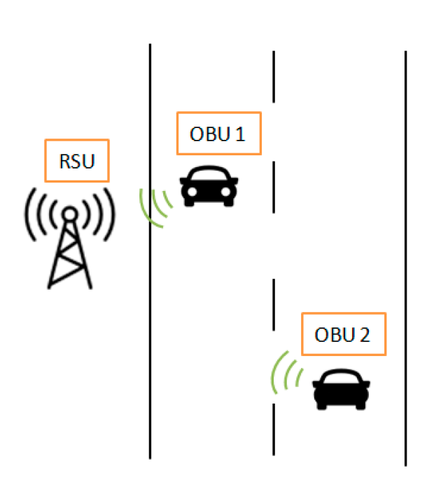
In any application for vehicular communication, there are two components: Road site unit (RSU) and on-board unit (OBU). Their responsibilities are different due to their different positions on the road.
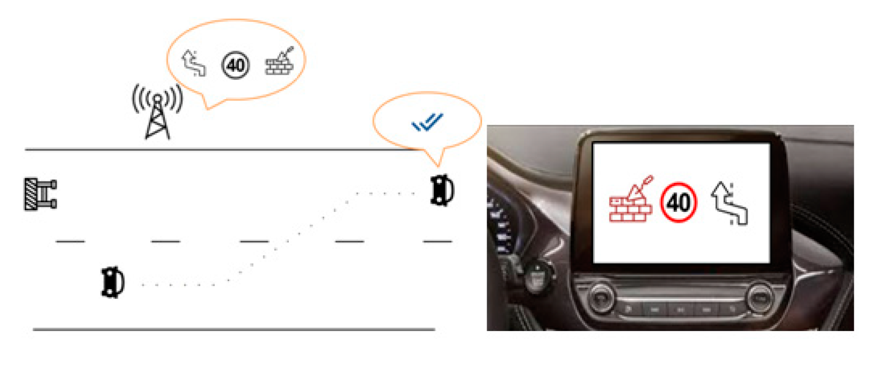
Figure 1 represents a real case, where the road infrastructure or RSU has the message with the information available for the vehicle.
The purpose of the OBU in the vehicle consists of taking the information from the RSU, filtering it in function of the driver’s interest, and displaying it on the screen of the vehicle, but with the necessary time for a safe driver reaction. An example of application would be the
Figure 2.
This way is considered the optimal method, avoiding overload of the network with unnecessary messages, because the displayed messages are enough for enhancing safety and efficiency. In addition to this, there will be an RSU, each 100 meters, which will avoid a message being too heavy for the right delivery.
In contrast with current methods which can recognize traffic signs with cameras, our method solves the main issues of camera usage, which are poor visibility of the traffic signal or bad behaviors in adverse weather conditions. With V2I methods, you have this data in any case and with time enough. It also facilitates really more road data than visual methods.
Once the system operation has been reviewed, in the following subsections, it is described the different steps to carry it out.
3.2. Communication Technology
To achieve the overall goal, which was described in the previous section, it was necessary to have different communication technologies and microprocessors. The technology created the network with adequate performance (in terms of latency, data rate, and data payload) and the microprocessor carried out its control, although it needed the right algorithm.
With the goal of taking the best relationship between cost and performance, Arduino and Raspberry microprocessors were tested. They are widely used for home automation, robotics, and Internet of Things (IoT). Some solutions checked in
Section 2 were used for the same microprocessor for its solution regardless of its work role. In this work, both were used because we wanted to take advantage of the faster response of the Raspberry for a better response in the vehicle, and take advantage of the robustness of the Arduino in the RSU for ensuring the right delivery of the message with the best performance available.
Three microprocessors were used depending on the communication technology needed:
Arduino UNO R3: It is a robust microprocessor and it ensures the right operation of any algorithm. The technical specifications are in [
20]. It was used for all the technological solutions, excluding Wi-Fi option, because using a microprocessor with the Wi-Fi integrated was preferred.
Raspberry Pi 3B+: Last release of Raspberry in the selection time, its technical specifications can be found in [
21]. It was used for all the technological solutions, taking advantage of its faster operation and the embedded Wi-Fi 802.11 b/g/n/ac.
Arduino UNO WIFI REV2: Last version of Arduino in the selection time, its technical specifications are in [
22]. This microprocessor integrated the Wi-Fi 802.11 b/g/n.
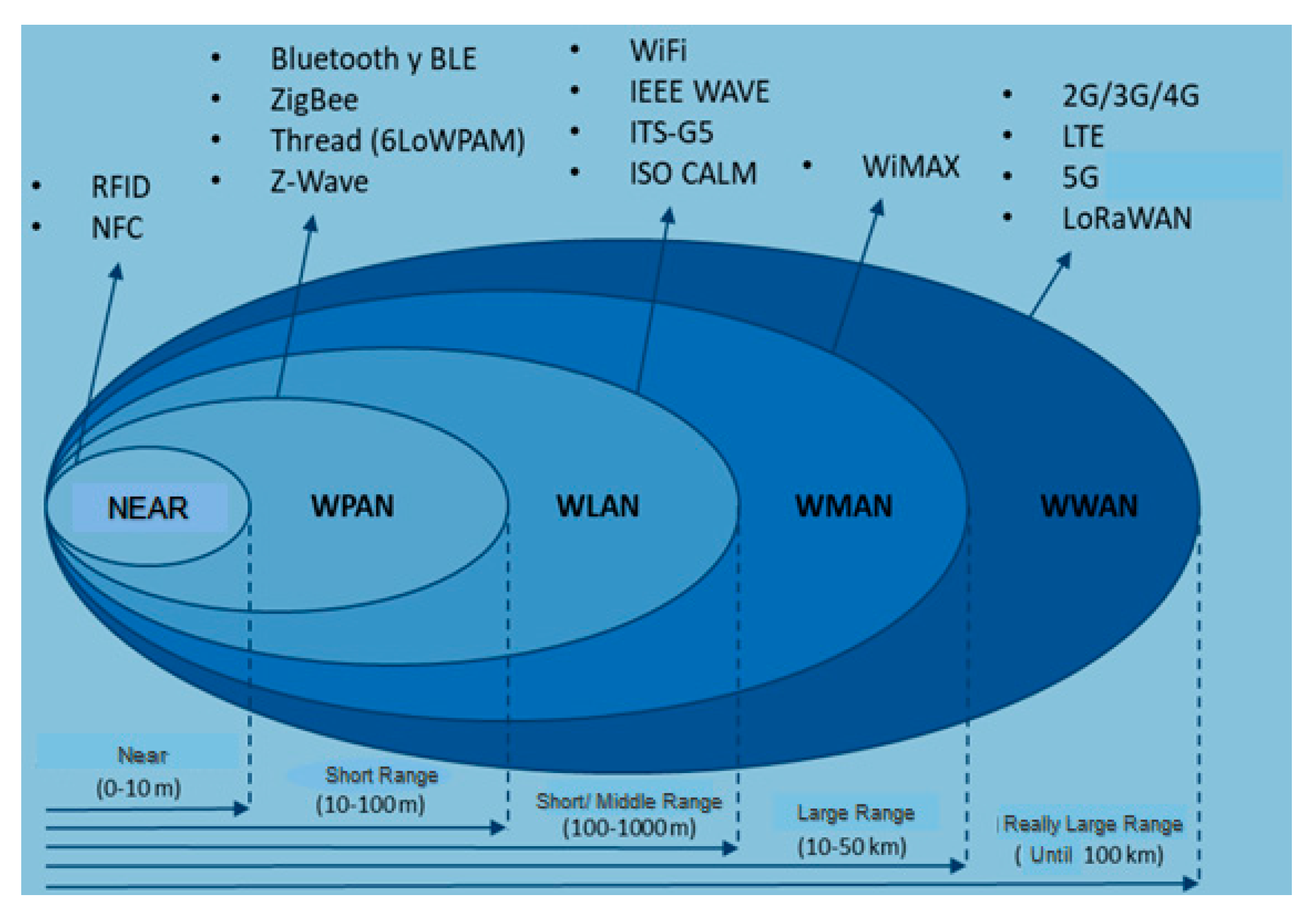
Following the microprocessors’ selection, the next step was the choice of communication technologies. There is a wide range of technologies in the market, as it can be seen in
Figure 3. Particularly, the desired technology must have a short/middle range. In other words, it has to cover a minimum distance of 100 m, in accordance with the specifications of
Section 1.
Inside the short/middle range technologies, which were available in the market, it was selected the following technologies, which have been collected in
Table 1.
Following
Table 1, three technologies were chosen: ZigBee, nRF24L01, and Wi-Fi:
DIGI XBEE S2C: Radiofrequency module from DIGI XBee, whose operation protocol is ZigBee, which is inside 802.15.4 radiofrequency protocol. Its technical specifications are in [
23].
nRF24L01+: Radiofrequency module with an integrated antenna amplifier. It operates inside 802.15.4 radiofrequency protocol. Its technical specifications can be found in [
24].
Wi-Fi IEEE 802.11 b/g/n: Wi-Fi module embedded in the Arduino Uno WiFi REV2. The technical specifications of the Wi-Fi module are in [
25].
Wi-Fi IEEE 802.11 b/g/n/ac: Wi-Fi module embedded in the Raspberry Pi 3B+. The technical specifications of the Wi-Fi module are in [
26].
The obvious choice for Wi-Fi technology could have been the standard 802.11p. Nevertheless, these modules required a high investment, which was out of our selection criteria. In this way, with the last version of both microprocessors, it was achieved two Wi-Fi technologies with a low cost.
3.3. Algorithms
After checking the communication technologies and microprocessors, the next step is to continue with the assembly of the device and the development of the algorithm.
The chosen microprocessor determined the programming language and the communication technology determined the connection bus. The algorithm languages and the interfaces are shown in
Table 2.
Working with two different microprocessors increased the difficulty of the task. They use different programming languages and work with different clock speeds, which made their synchronization harder.
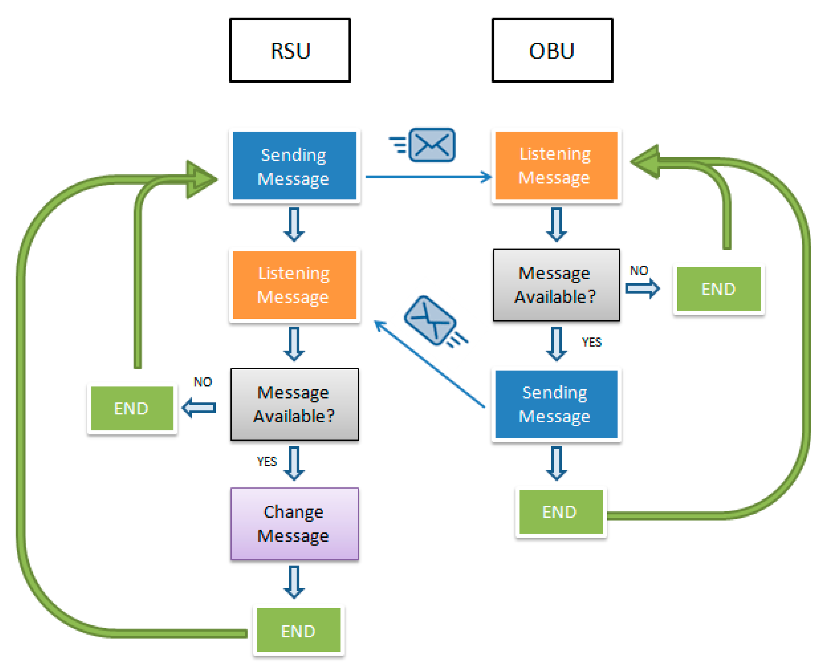
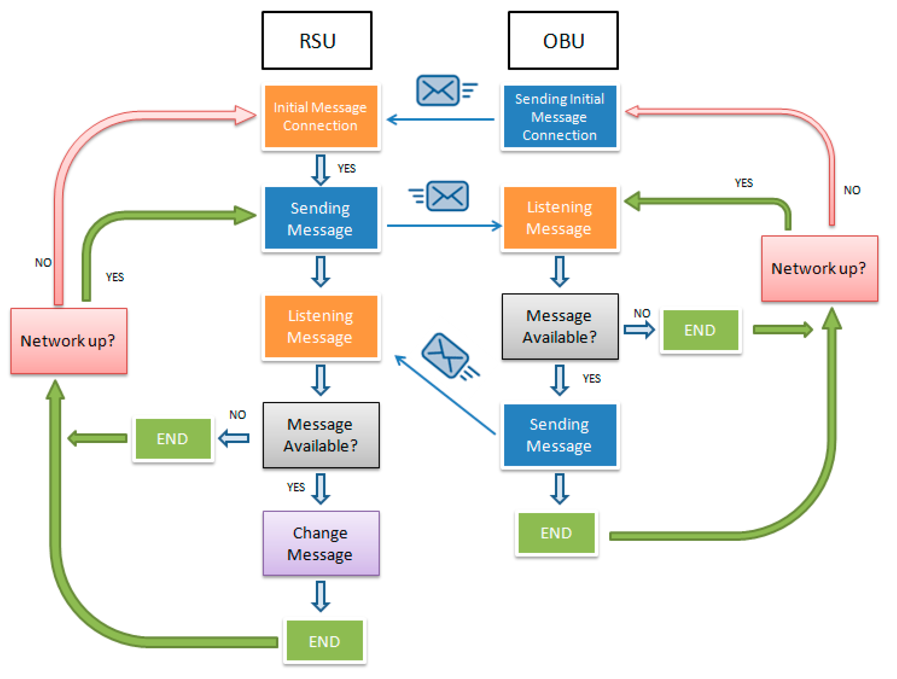
The following paragraphs give an explanation of the control algorithms through flow diagrams in
Figure 4 and
Figure 5. The algorithm code is available in the
Appendix A.
The RSU sent a message to the OBU when it was in its range. Then the OBU received it and sent back a reception check, which let the RSU change the message.
Wi-Fi: In this case, the communication mode “Wi-Fi Direct” was used. It is a new method, which allows communication between devices without a gateway. In this way, the RSU (Arduino) set the communication channel with the client (OBU, Raspberry).
Contrasting
Figure 5 with
Figure 4, both diagrams are different in the way that they establish the connection to send messages in any direction. While in the ZigBee, the network was made up with an active coordinator. With Wi-Fi, the client had to send a message to the coordinator which was supporting the network.
nRF24L01+: In these modules, if the network was not wide, it was not necessary to define roles. Otherwise, one of the modules must be the coordinator of the network. The operation diagram of this module is the same as
Figure 4.
3.4. Devices Configurations
In order to optimize the results and achieve the best behavior, the main parameters of the devices were studied. The next lines highlight the main parameters, their values, and theirs meanings:
ZigBee: These devices were configured through XCTU tool. Regardless if the device was controlled by Arduino or Raspberry, the main parameters were:
- ○
Networking:
ID PAN ID: It determined the network to join. Value Range: 0–0 × FFFFFFFFFF. Value: 0.
JV, channel verification: Each network needed a coordinator, so it enabled a router to verify the existence of a coordinator on the same channel. Value: Enable (only for router devices).
CE, coordinator enable: Each network needed a coordinator, so it enabled the device to work as a coordinator. Value: Enable (router devices have this parameter disabled).
- ○
Addressing:
DH, destination address high: It set the destination address. Value: 0000. This value let the router communicate with the coordinator of the network without writing its address.
DL, destination address low. Value: 0000
NI, node identifier: It set the name of the device. Value: Coordinator/router/router 2.
- ○
RF interfacing:
- ○
Security:
EE encryption enable: Enable or disable ZigBee encryption. Value: Enable. So, the device had the network encrypted.
EO encryption options: Type of Security. Value: 0. It was the most simple security level, where only restrictions joined to the network.
KY encryption key: Password. Value: Password
- ○
Serial interfacing:
BD baud rate: It was the serial interface baud rate. Value: 9600. It must be the same as that of the microprocessor.
RO, packetization timeout: It set number of character times delay before transmissions began. Range value: 0 × 0–0 × FF. Value: 3. It was an experimental value. The higher the value, the more time it spent reading the message. If the value was too low (for instance, 0), it split up the message.
AP, API enable: It enables API mode communication. Value: Transparent mode. Enable API mode if you want to interact with the network capabilities of the module, but it was not our case.
Wi-Fi:
The configuration of the technology is fixed in Arduino. You can only define the role of the device in the network. Meanwhile, in Raspberry you can configure two parameters:
- ○
socket.SOCK_STREAM: To achieve flow sockets under TCP protocol (Transmission Control protocol) for safe and reliable connections. The alternative is SOCK_DGRAM which uses UDP protocol (User Datagram Protocol). It is less reliable than TCP.
- ○
socket.AF_INET: To determine the family of socket, if the device will use networks or not. The alternative is AF_UNIX, but it is outdated.
nRF24L01+:
The configuration of the technology is the same on both Arduino and Raspberry. The parameters are:
- ○
SetPayloadSize: It sets the number of bytes in the payload. Value: 32. It is the maximum payload size.
- ○
SetChannel: It sets the RF communication channel. Range: 0–125. Value: 0 × 76. Both devices must have the same number.
- ○
SetDataRate: It sets the transmission data rate. Value: 1 Mb/s. It is the default value and the recommendation of the manufacturer.
- ○
SetPALevel: It sets the power amplifier level. Value: RF24_PA_MAX. It has lower levels, but it would set a weaker signal.
- ○
SetAutoACK: Enable or disable auto acknowledge packets. It sends an automatic answer if the message is rightly submitted. It is enabled by default.
- ○
SetRetries: It sets the number and delay of retries upon failed submit. Value: (15,15). It would try to send the message 15 times, with a time gap of 15 × 250 µs. This parameter is only configurable in the network maker.
- ○
EnableDynamicPayloads: It lets you send custom payloads packets. It is enabled by default.
4. Experimentation
4.1. Approach
Once the communication systems were assembled and programmed, the performance of the devices were validated. For that, the modules were submitted to a test bed where a validation methodology was established in order to compare the technologies. The developed validation methodology was based on several studies and articles from others authors.
Summarizing the consulted studies, [
27] highlights the critical parameter to control in any V2X technology test, but they did not make physical tests. The most important parameters are the latency of the messages, lost, and right messages rate and the range which is covered by the modules. On the other hand, the analysis of the experimental data was based on the methods carried already out by [
28] for 802.11p technologies and [
29] for C-V2X technologies. Both made latency and range tests, but they did not analyze other parameters which are important, too. The aim of our experimental tests was to provide as much information as possible about the real behavior of the device.
To carry it out, it was used the installations of CIDAUT Foundation in the locality of Mojados and in the Technological Park of Boecillo, both in Valladolid (Spain). The schedule of the tests is summarized in
Figure 6,
Figure 7 and
Figure 8.
In the first place, preliminary tests to ensure the operation of the technology, which would be validated later, were carried out. With the algorithm built and modules assembled, the two modules were tested to ensure the correct communication. The design of the test can be seen in
Figure 6. They took place in CIDAUT Foundation installations in the Technological Park of Boecillo.
The devices were at the same height, avoiding obstacles between them. The distance between them was 20 m, which was a large enough distance to have a reliable operation.
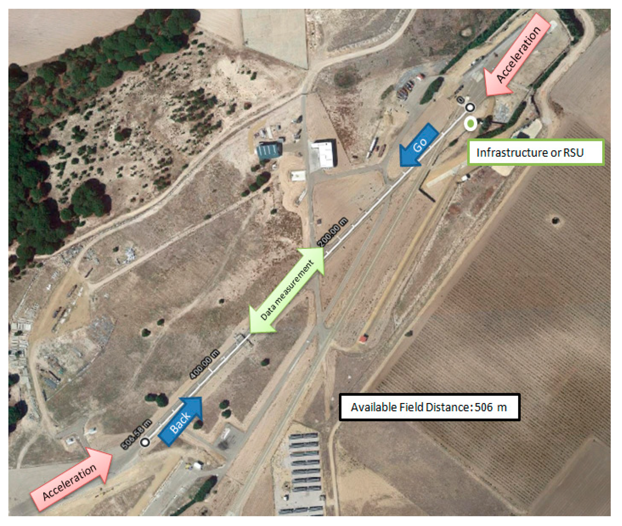
Then it was analyzed the capabilities and limitations of the devices with the test bed in the CIDAUT Foundation installations in Mojados, which can be seen in
Figure 7.
The main road had a length of 506 m with available open space at the beginning and end of the road for accelerating and braking to the desired speed. The tests were carried out as a sequence of a round trip in different operation conditions for taking different measures. The equipment was a vehicle, a lifting crane, and a ladder.
Maximum distance and kind of signal. The aim was to measure the distance covered and if the distance was constant regardless of the orientation of the module (the vehicle used was moving at 30 km/h).
Dependence on vehicle speed. The vehicle was driven at three different speeds: 50, 70, and 90 km/h.
Dependence on RSU height. The vehicle was driven at 50 km/h, but the height of the RSU was variable: 2, 5, and 10 m.
Dependence on RSU position. The vehicle was driven at 50 km/h, but this time the RSU was located in different positions of the road: On one side (0 m), in the center (2m), and on the other side (4 m).
Dependence on data rate. If the technology allowed it, the data rate was changed and it was analyzed if it had influence in the module operation.
The round trip consisted of six trips, three outward and three return, which was enough to take data and know the capabilities of the devices. The driven car was a Toyota Hybrid Auris, where the communication technology was outside of the car and in its roof. There was one round trip per each variable change.
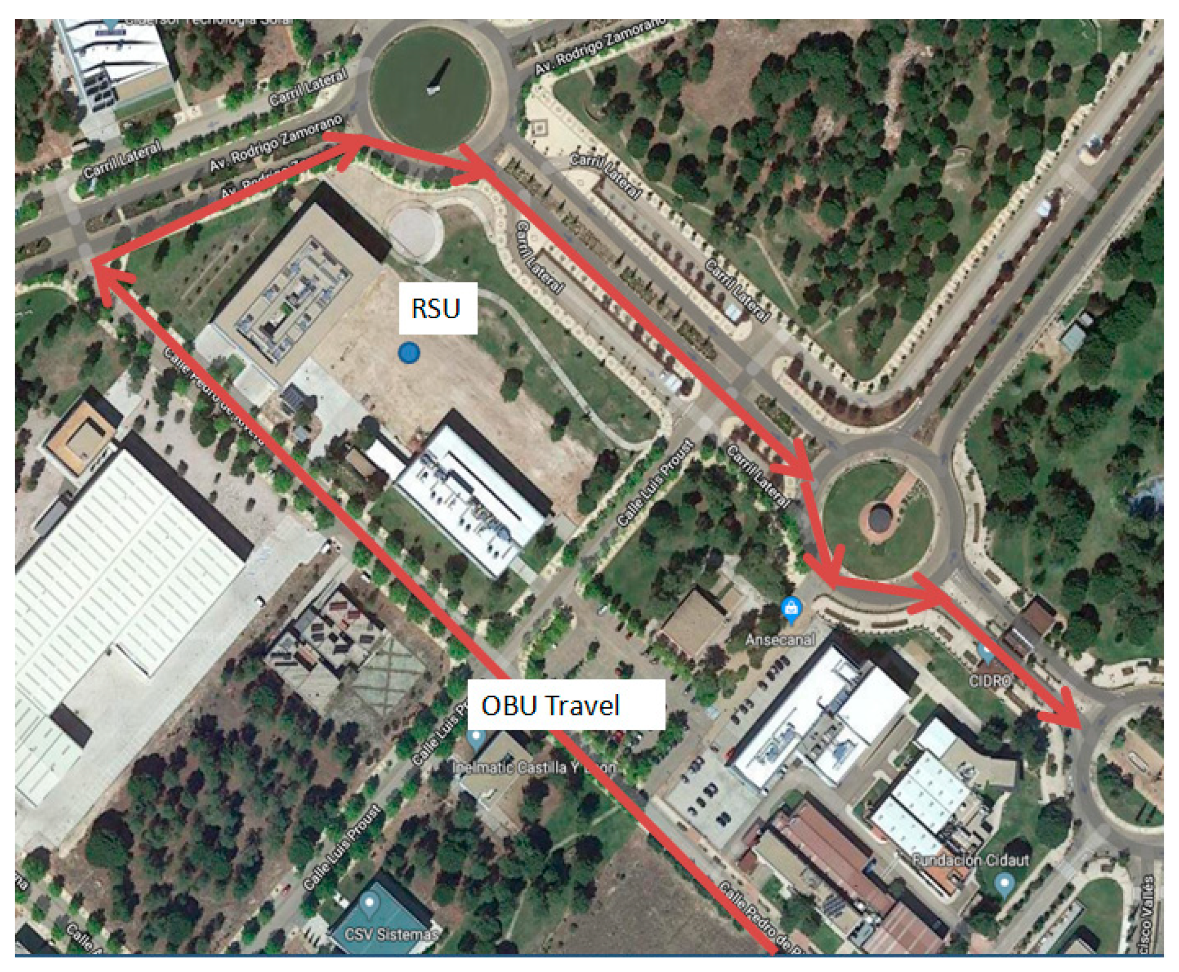
The methodology validation was completed after performing the last test around the CIDAUT Foundation buildings in the Technological Park of Boecillo, which can be seen in
Figure 8, where the dependence of the obstacles in the right operation of the devices was analyzed
During the test, the RSU was in the same place, as can be seen in
Figure 8. One side had buildings, while on the other there was a direct line of sight between both. Comparing both data, it can be appreciated the obstacles’ influence.
The car used was the same as the previous test in Mojados. The maximum car speed was 40 km/h, because that is the road speed limit.
4.2. Results
After the preliminary test and some of the field tests, there were important results for each technology, which are shown in
Table 3.
For a complete comprehension of
Table 3, the measured features are explained:
Range, distance covered by the module in straight line;
Latency, time spent in sending messages and receiving the check. It depended on the technology, the physical connections, and the clock speed of the microprocessor. The time between messages depended on the latency. The higher it was, the more time was needed to send the next message.
On completing the field test, there were data of the operation of the devices and when its operation changed depending on the scenery. The influence of the RSU height, position, car speed, and its operation when there is not direct line of sight will be tested.
5. Discussion
After monitoring the performance of the modules for V2I communication, the most important conclusions, which will let us go on with the study, are highlighted.
Based on results, a decision tree was made, as can be seen in
Figure 9. The aim was to show strengths and weaknesses of each technology by means of a possible application.
Regarding the decision tree, depending on the case, it recommended one technology or another. An example of the different five cases:
Small area + less time + more vehicles: For instance, urban areas. Areas with high traffic flow and which could require a quick reaction in case that (for instance) accidents takes place.
Small area + less time + less vehicles: For urban areas with less importance or where the flow of traffic is less than case 1. In this way, there was more time to take an action.
Small area + high time: Peri-urban areas. Outskirts of the city, where it was possible to give information to the drivers, improving their route before going into the city.
Large area + high time: Highways or national roads. In this case, the technology ZigBee would send informative messages in broadcast mode (accidents, road works, and traffic signals), so there was no need of interaction.
Large area + less time: For example, intersections in national roads or highways, roads with low traffic flow, where it was possible to require a quicker reaction or response.
Contrasting technologies, the best technology in terms of communication speed is Wi-Fi. However, its really short range is an inconvenient because this device is out of our criteria of short/middle range. For this reason, this technology was not further tested.
Meanwhile, the technology based on ZigBee was the slowest one, although it had a wide range which paid off for the lack of speed. For example, with a vehicle speed at 50 km/h, driving 1000 m, it spent 72 s, which was enough time for a good communication.
The best ratio range/latency was offered by the nRF24L01+ module. It covered up to 1000 m, sending messages every 350 ms, allowing us to set a network with more flexibility than the one set by ZigBee because it sent messages more frequently.
The behavior also depended on the type of bus used for the physical connections (
Table 2). Arranging in decreasing speed order: The technology embedded was faster than SPI connection, which was faster than UART or USB. ZigBee made use of UART and USB connections, and nRF24L01+ made use of SPI connections.
Based on the information above and the available information of the communication technologies in
Section 3.2, we concluded that ZigBee is designed for home automation or applications, where it can operate with a low power consumption. That is the reason why it sends messages slowly. ZigBee is ready for slower data delivery. Although it is a limitation, this technology will go on under study. On the other hand, with the aim of knowing the influence of the microprocessors in the operation of the technology, we contrasted our results with the nRF24L01+ study carried out in [
11]. They had latencies of 128 ms, although it was a variable measure. Its maximum latency measured was 300 ms, against our maximum latency of 350 ms. This gap between studies was due to the microprocessors (because the device configuration was the same). Meanwhile, in [
11] they employed two Arduinos UNO. In this study an Arduino and a Raspberry were used. So the combination employed in [
11] was faster and stronger. Using the same microprocessor made easy the synchronization because the devices had the same clock speed. But it is important to know the lost messages rate to compare both studies, which there was not data available.
Finally, it must be pointed out that after the completed test bed, we will have a better knowledge of the variable operation of the ZigBee and nRF24l01+ in diverse scenery. After the test bed, the most suitable technology will be used in a vehicle for the proof of concept.
Author Contributions
Conceptualization, A.M., E.C., and J.R.; data curation, A.M. and J.R.; formal analysis, A.M. and J.R.; funding acquisition, A.M., E.C., and J.R.; investigation, A.M.; methodology, A.M. and J.R.; project administration, E.C. and J.R.; resources, E.C. and J.R.; software, A.M.; supervision, E.C. and J.R.; validation, A.M., E.C., and J.R.; visualization, J.R.; writing—original draft, A.M.; writing—review and editing, A.M., E.C., and J.R. All authors have read and agreed to the published version of the manuscript.
Funding
This research was funded by the Institute for the Enterprise Competitiveness in Castile and Leon (ICE), number file: CCTT1/17/VA/0006.
Conflicts of Interest
The authors declare no conflict of interest.
Appendix A
In this Section of the article, it will be exposed the algorithms used in the microprocessors. These algorithms managed the communication technology.
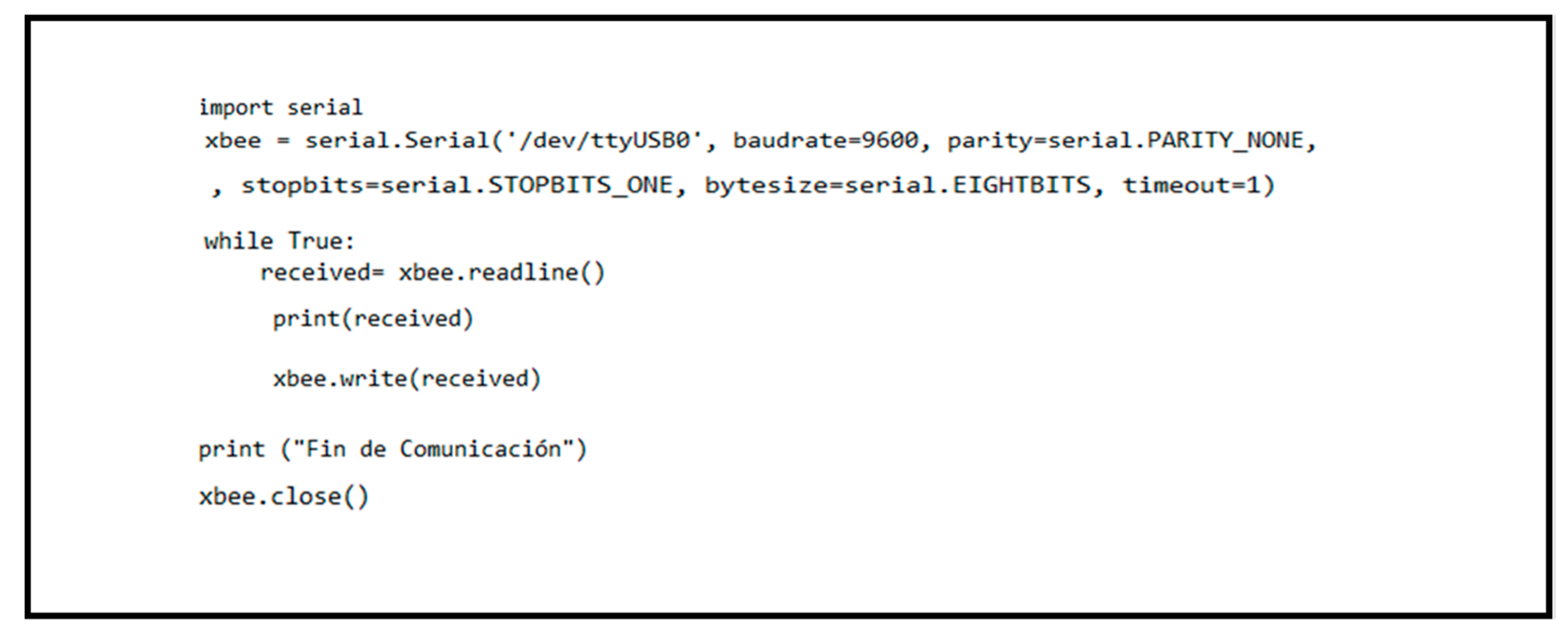
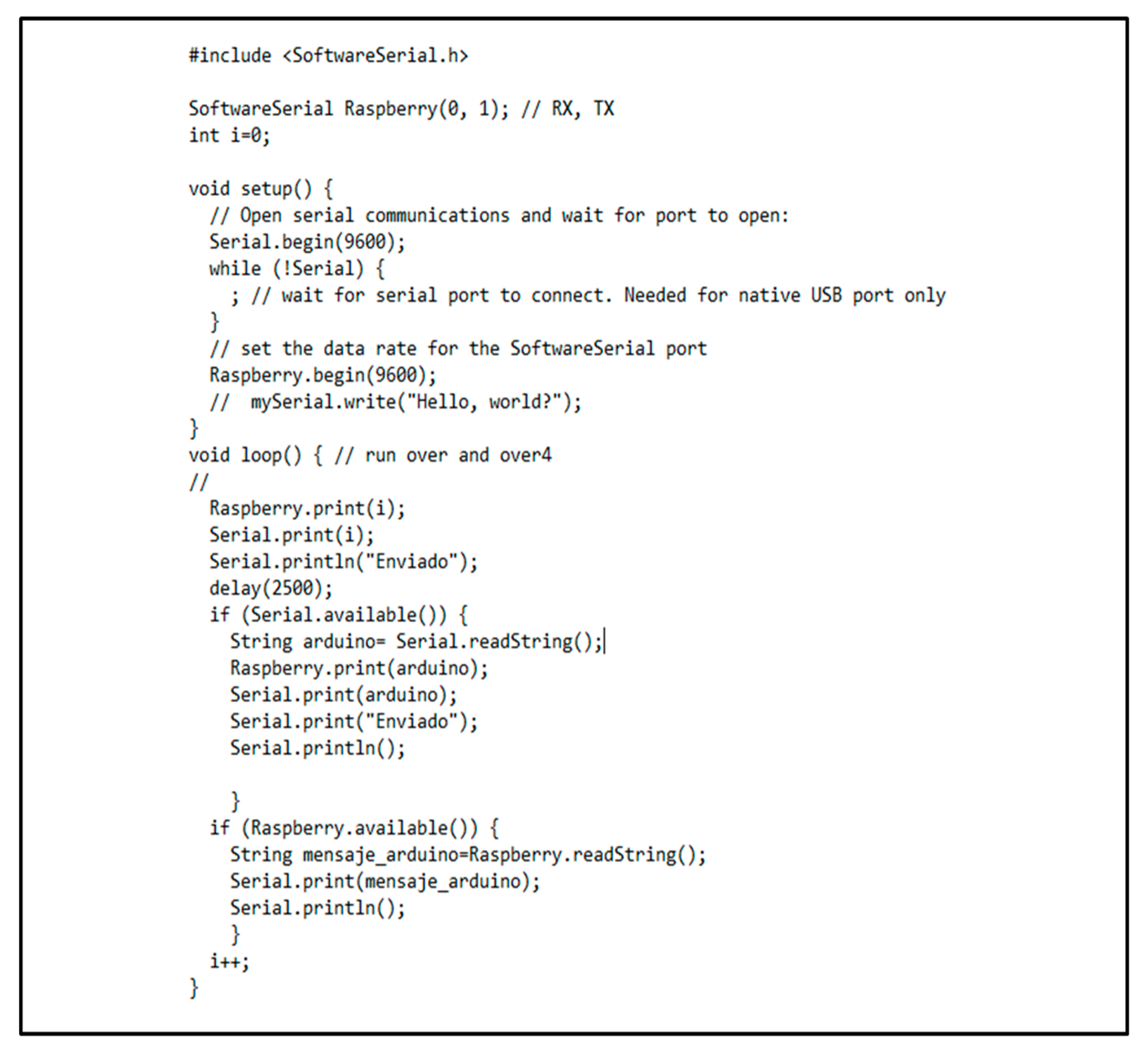
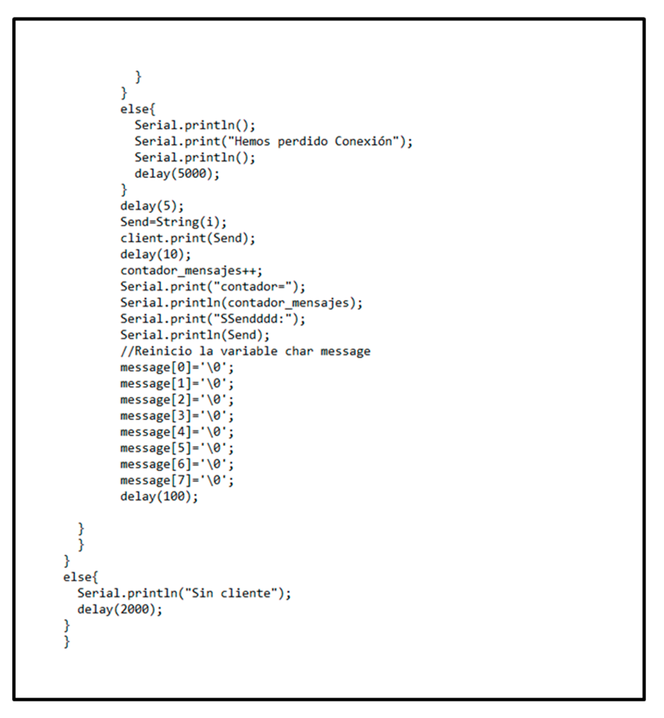
ZigBee: Using the library “Serial” in both microprocessors, the algorithm was created, which it was shown in
Figure A1 and
Figure A2.
Figure A1.
Raspberry Pi programming for XBee devices with ZigBee protocol.
Figure A1.
Raspberry Pi programming for XBee devices with ZigBee protocol.
So, the node called OBU was in listening mode until the reception of the data. When it received the data, it set a verification. In this way, when the RSU received the verification of the OBU, it changed the message.
Previously, it was necessary to define the connection ports of the communication modules and configure the devices for an efficient synchronization.
Figure A2.
Arduino programming for XBee devices with ZigBee protocol.
Figure A2.
Arduino programming for XBee devices with ZigBee protocol.
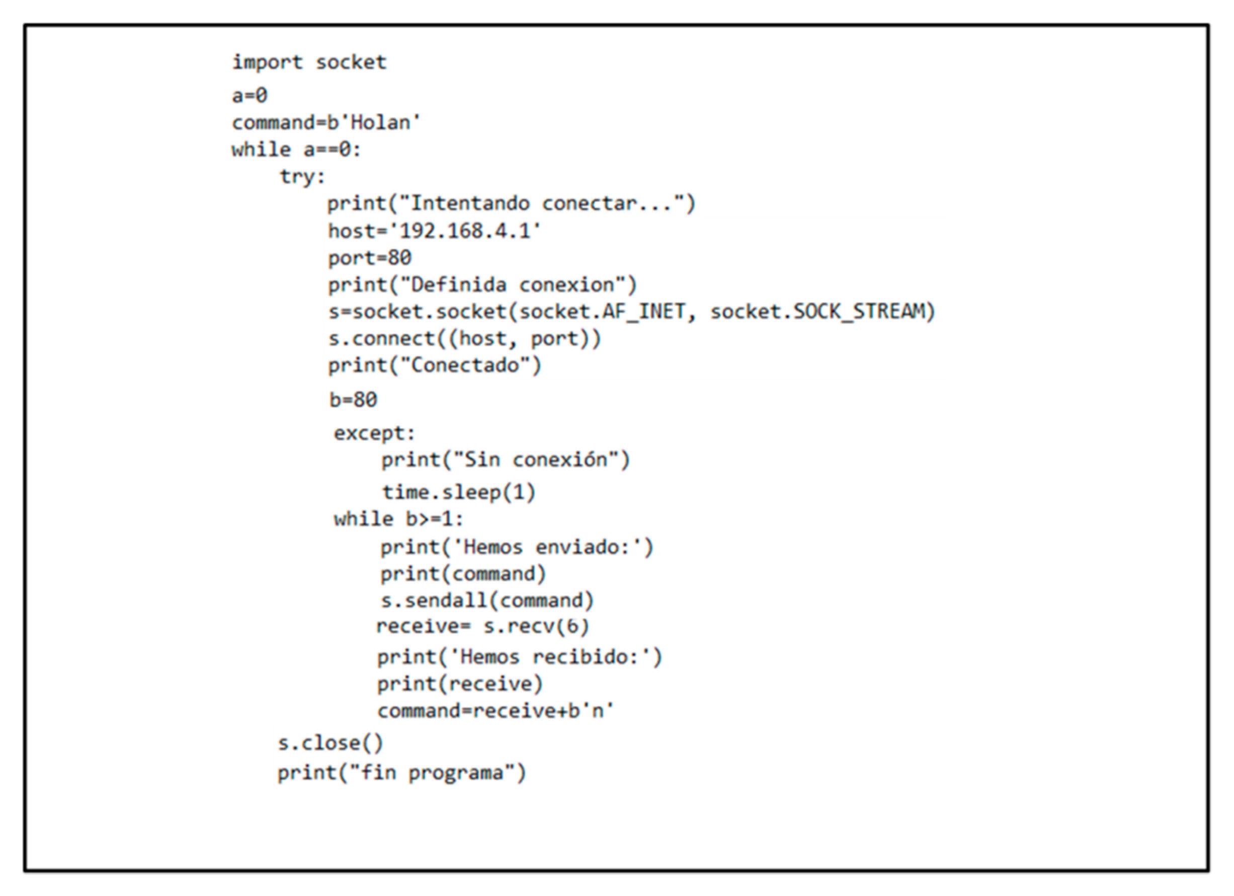
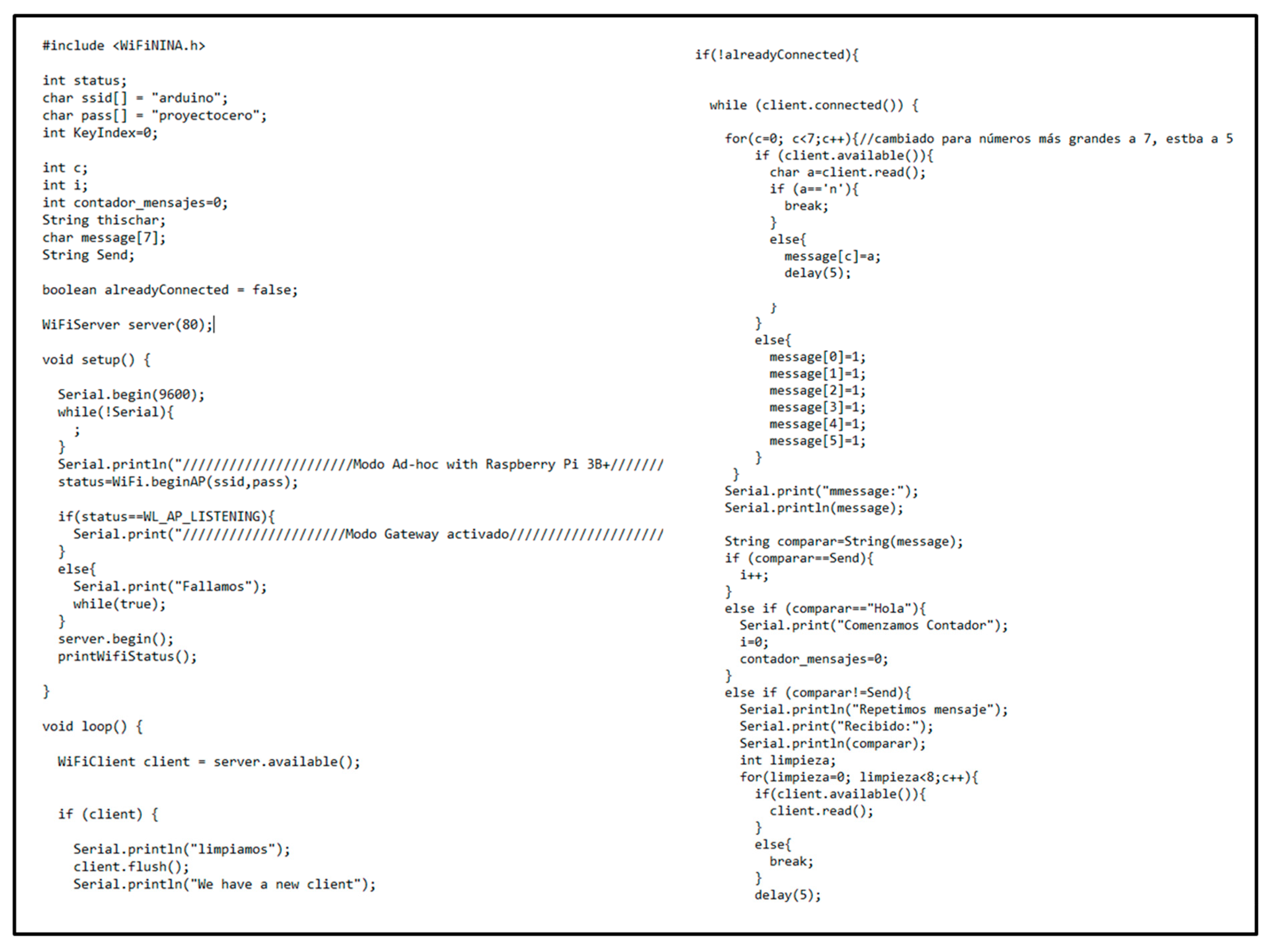
Wi-Fi: Using library “WIFININA” in Arduino and “sockets” in Raspberry, it was created a communication in Wi-Fi Direct mode. Both IP (Internal Protocol) were visible, which let them connect in mode ad hoc. The codes can be seen in
Figure A3,
Figure A4 and
Figure A5. The particularity can be found in the connection beginning. The RSU made the network up, but due to the protocol, the network was not available until the OBU sent a message to the RSU, which meant a conversation request. Previously, each device was configured for being able to establish the connection and be able to understand each other for a bidirectional communication.
Figure A3.
Raspberry Pi programming for embedded Wi-Fi.
Figure A3.
Raspberry Pi programming for embedded Wi-Fi.
To achieve the ad hoc communication mode, enabling the RSU with the Arduino as gateway was necessary to support the network.
Figure A4.
Arduino programming for embedded Wi-Fi, part 1 of 2.
Figure A4.
Arduino programming for embedded Wi-Fi, part 1 of 2.
Figure A5.
Arduino programming for embedded Wi-Fi, part 2 of 2.
Figure A5.
Arduino programming for embedded Wi-Fi, part 2 of 2.
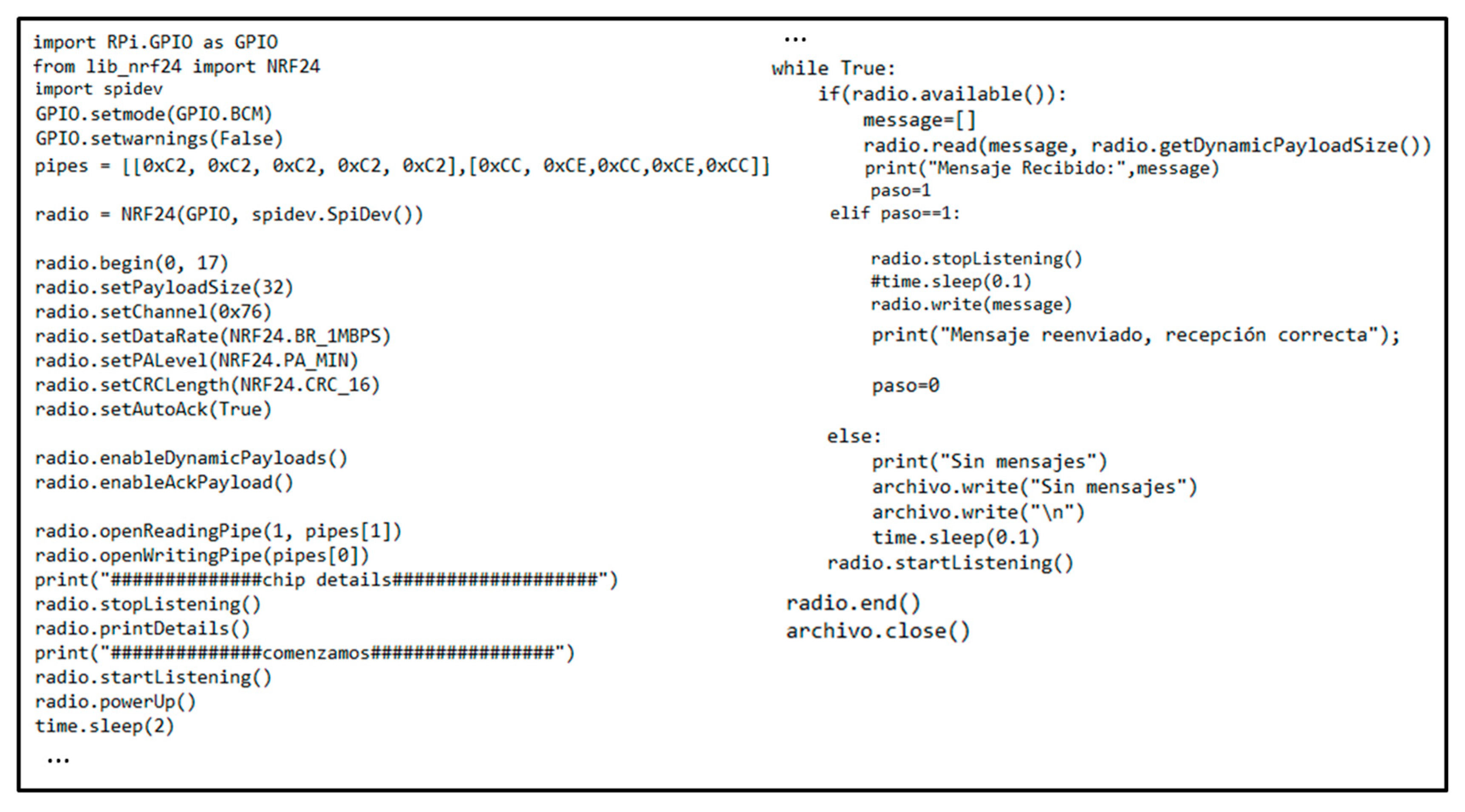
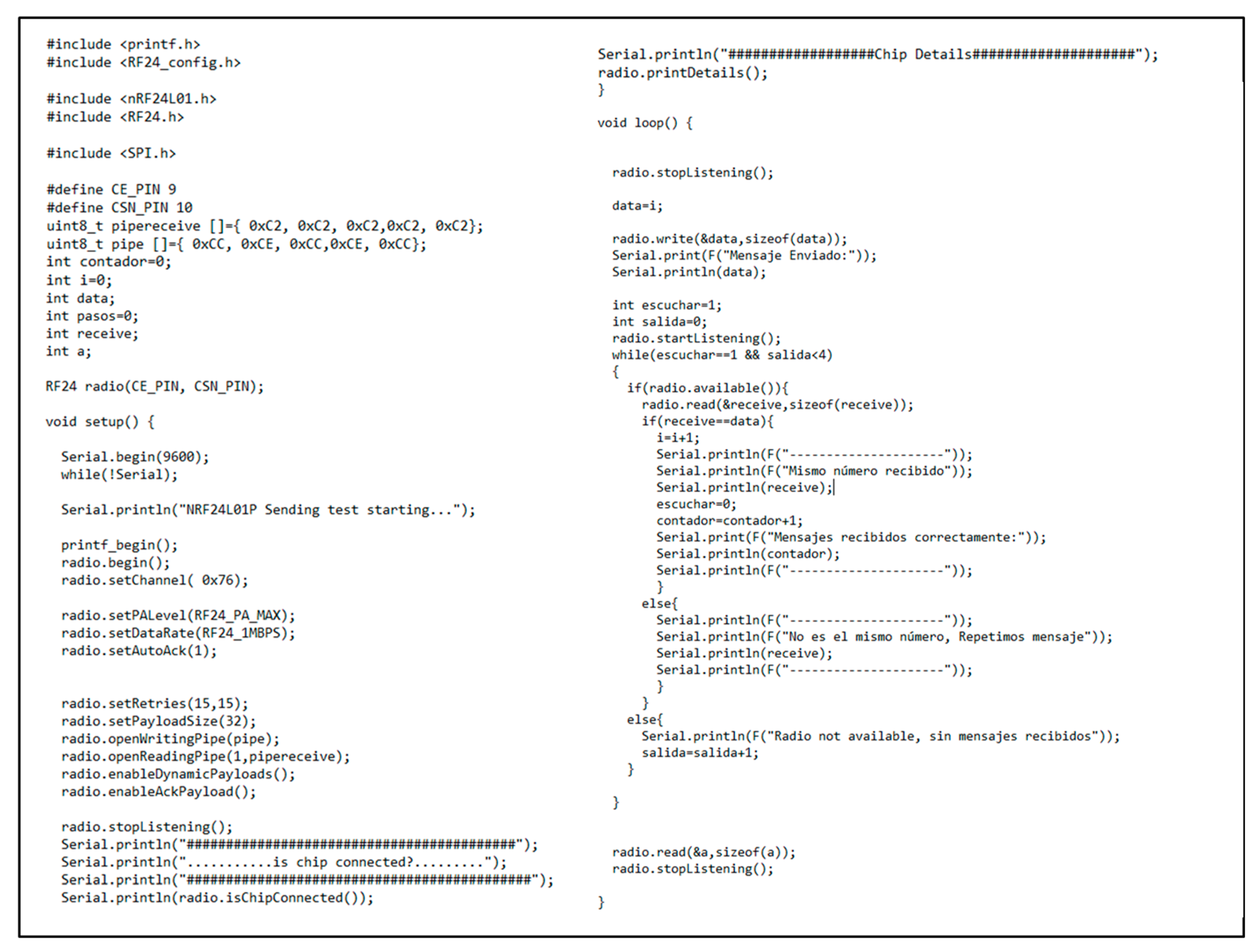
nRF24L01+: With the library “Tmrh20” for Arduino and “Blaavery” for Raspberry Pi, letscontrol the communication devices in both microprocessors. In
Figure A6 and
Figure A7, the algorithms can be found, which began configuring modules for synchronizing them.
Figure A6.
Pi programming for nRF24L01+ device.
Figure A6.
Pi programming for nRF24L01+ device.
The code was based on setting up the OBU in listening mode for receiving messages from the RSU. When it received the message, the OBU sent back a verification response. In this way, the RSU was aware of the right reception and got on with the next messages.
Figure A7.
Arduino programming for nRF24L01+ device.
Figure A7.
Arduino programming for nRF24L01+ device.
References
- European Commission. The Directorate-General for Transport; Annual Accident Report; European Commission: Brussels, Belgium, 2018. [Google Scholar]
- European Federation for Transport and Environment. CO2 Emissions from Cars: The Facts; European Federation for Transport and Environment: Brussels, Belgium, 2018. [Google Scholar]
- European Commission. Available online: https://ec.europa.eu/transport/themes/its/c-its_en (accessed on 25 October 2019).
- European Commission. Study on the Deployment of C-ITS in Europe: Final Report; European Commission: Brussels, Belgium, 2016. [Google Scholar]
- 5GAA. C-ITS Vehicle to Infraestructure Service: How C-V2X Technology Completely Changes The Cost Equation for Road Operators; Whit Paper; 5G Automotive Association: Munich, Germany, 2018. [Google Scholar]
- Analysys Mason Limited, 5GAA. Socio-Economics Benefits of Cellular V2X; 5G Automotive Association: Munich, Germany, 2017. [Google Scholar]
- European Commission. Available online: https://ex.europa.eu/digital-single-market/en/5g-europe-action-plan (accessed on 10 October 2019).
- Gheorghiu, R.A.; Iordache, V.; Minea, M. Messaging capabilities of V2I networks. In Proceedings of the 11th International Conference Interdisciplinarity in Engineering (INTER-ENG), Tirgu-Mures, Romania, 5–6 October 2017. [Google Scholar]
- Gheorghiu, R.A.; Minea, M. Energy-efficient solution for vehicle prioritisation employing ZigBee V2I communications. In Proceedings of the International Conference on Applied and Theoretical Electricity (ICATE), Craiova, Romania, 6–8 October 2016. [Google Scholar] [CrossRef]
- de la Fuente, D.; Moner, H.; Gonzalvez, J. Comunicaciones Infraestructura a Vehículo basadas en IEEE 802.15.4 para Señalización Vial Inalámbrica. In Proceedings of the Libro de Actas del XXVI Simpósium Nacional de la Unión Científica Internacional de Radio (URSI), Leganés, Madrid, Spain, 7–9 September 2011. [Google Scholar]
- Saha, H.; Mandal, S.; Mitra, S.; Banerjee, S.; Saha, U. Comparative Performance Analysis between nRF24L01+ and XBEE ZB Module Based Wireless Ad-hoc Networks. Comput. Netw. Inf. Secur. 2017, 9, 36–44. [Google Scholar] [CrossRef]
- Hernandez-Oregon, G.; Rivero-Angeles, M.E.; Chimal-Eguía, J.C.; Campos-Fentanes, A.; Gallardo, J.G.J.; Estevez-Alva, U.O.; Juarez-Gonzalez, O.; Rosas-Calderon, P.O.; Sandoval-Reyes, S.; Mechaca-Mendez, R. Performance Analysis of V2V and V2I LiFi Communication Systems in Traffic Lights. Wirel. Commun. Mob. Comput. 2019, 2019, 4279683. [Google Scholar] [CrossRef]
- Nawaz, T.; Seminara, M.; Caputo, S. IEEE 802.15.7-Compliant Ultra-Low Latency Relaying VLC System for Safety-Critical ITS. IEEE Trans. Veh. Technol. 2019, 68, 12040–12051. [Google Scholar] [CrossRef]
- Kuppusamy, P.; Muthuraj, S.; Gopinath, S. Survey and Challenges of Li-Fi with Comparison of Wi-Fi. In Proceedings of the International Conference on Wireless Communications, Signal Processing and Networking (WiSPNET), Chennai, India, 23–25 March 2016. [Google Scholar]
- Giordani, M.; Zanella, A.; Zorzi, M. LTE and Millimiter Waves for V2I Communications: An End to end performance comparison. In Proceedings of the VTC2019-Spring, Kuala Lumpur, Malaysia, 28 April–1 May 2019. [Google Scholar]
- Phu, C.N.V.; Farhi, N.; Haj-Salem, H.; Lebacque, J.P. A vehicle-to-infrastructure communication based algorithm for urban traffic control. In Proceedings of the 5th IEEE International Conference on Models and Technologies for Intelligent Transportation Systems (MT-ITS), Napoles, Italy, 26–28 June 2017. [Google Scholar] [CrossRef]
- Phanindra, J.N.; Srinivas, V. Raspberry Pi Based Traffic Density Monitoring and controlling System. Int. J. Res. Appl. Sci. Eng. Technol. 2017, 5, 393–400. [Google Scholar] [CrossRef]
- Hua, Q.; Yu, K.; Wen, Z.; Sato, T. A Novel Base-Station Selection Strategy for Cellular Vehicle-to-Everything (C-V2X) Communications. Appl. Sci. 2019, 9, 556. [Google Scholar] [CrossRef]
- Tawfeek, M.H.; Zhang, H.; Gao, J.; El-Basyouny, K. Connected vehicle V2I communication application to enhance driver awareness at signalized intersections. In Proceedings of the Canadian Society for Civil Engineering Conference, London, UK, 1–4 June 2016. [Google Scholar]
- Arduino. Available online: https://store.arduino.cc/arduino-uno-rev3 (accessed on 20 March 2019).
- Raspberry Pi. Available online: https://www.raspberrypi.org/products/raspberry-pi-3-model-b-plus/ (accessed on 20 March 2019).
- Arduino. Available online: https://store.arduino.cc/arduino-uno-wifi-rev2 (accessed on 20 March 2019).
- Digi. Digi XBee®S2C 802.15.4 RF MODULES; Digi: Shah Alam, Malaysia, 2018. [Google Scholar]
- Nordic Semiconductor. nRF24L01+ Single CHIP 2.4 GHz Transceiver. In Preliminary Product Specification v1.0; Nordic Semiconductor: Trondheim, Norway, 2008. [Google Scholar]
- Ublox. Data Sheet; NINA-W10 Series: Stand-Alone Multiradio Modules; Ublox: Thalwil, Switzerland, 2019. [Google Scholar]
- Cypress. Available online: https://www.cypress.com/products/wi-fi-bluetooth-combos (accessed on 18 March 2019).
- Wang, J.; Shao, Y.; Ge, Y.; Yu, R. A survey of Vehicle to Everything (V2X) Testing. Sensors 2019, 19, 334. [Google Scholar] [CrossRef] [PubMed]
- Demmel, S.; Lambert, A.; Gruyer, D.; Larue, G.S.; Rakotonirainy, A. IEEE 802.11p Empirical Performance Model from Evaluations on Test Tracks. J. Netw. 2014, 9, 1485–1495. [Google Scholar] [CrossRef]
- 5GAA. V2X Functional and Performance Test Report. In Test Procedures and Results; 5G Automotive Association: Munich, Germany, 2019. [Google Scholar]
© 2020 by the authors. Licensee MDPI, Basel, Switzerland. This article is an open access article distributed under the terms and conditions of the Creative Commons Attribution (CC BY) license (http://creativecommons.org/licenses/by/4.0/).
