1. Introduction
Due to the advantages of high gain, low profiles and simple feeding network, leaky-wave antennas (LWAs) have attracted a lot of attention since being proposed in the 1940s [
1]. According to the operating principles, LWAs can be generally divided into two categories, uniform LWAs and periodic LWAs [
2,
3,
4]. Compared with uniform LWAs, periodic LWAs exhibit a large scanning range and flexible design schemes, which make them widely used in millimeter-wave bands [
5,
6]. One approach to achieving beam-scanning capability is utilizing the periodical shape changing of transmission line (such as triangle-truncated double-side parallel-strip lines [
7] and bends of sharpness [
8]). Another demonstrated method is sinusoidally modulating the surface impedance of the LWA [
9,
10,
11,
12]. Some previous research about sinusoidally modulated reactance surface (SinMRS) has shown the great advantages in the synthesis of radiation patterns. For instance, a simultaneous tapering of the leaky-wave leakage rate and pointing angle along the leaky radiator was used to synthesize radiation beams [
13]. Cosine-tapered designs were performed to reduce sidelobe levels and tune the pointing direction over a wide range [
14]. Recently, an array of non-uniform SinMRSs with application to near-field focused leaky-wave radiation in the backward Fresnel zone were proposed [
15].
For LWAs based on SinMRS, at least five kinds of unit cells have to be selected to mimic the sinusoidal distribution of surface impedance [
16], which makes the construction of LWAs extremely complex. More recently, SinMRS, constructed with five kinds of tunable unit cells, was utilized to validate beam steering at fixed frequency [
17,
18]. In theory, the bias voltage of each kind of unit cell should be independently controlled, which leads to the complex bias network and additional energy loss. To avoid this situation, different kinds of unit cell are designed with various dimensions so that their surface impedances can satisfy the requirement under a uniform bias voltage control [
17,
18]. However, the distribution of surface impedance during one period is restricted in several fixed patterns, and the phase constant and attenuation constant of the SinMRS cannot be controlled independently. To overcome this, squarely modulated reactance surface (SquMRS), which is composed of only two kinds of unit cells, is proposed in [
19]. Since each kind of unit cell can be treated as a “macro cell” (a macro cell is loaded with only one tunable component) [
20], SquMRS can load much less tunable components, which makes it convenient to realize the independent control of phase constant and attenuation constant with the simpler biasing network.
In this paper, a novel SquMRS structure is proposed to generate the leaky-wave radiation. Firstly, the propagation properties of surface wave travelling along the SquMRS are discussed by using a numerical method based on the equivalent transmission lines model proposed in [
19]. In order to verify the feasibility of SquMRS, two LWAs have been designed based on SquMRS and SinMRS, respectively. Finally, a dual-beam LWA is presented that uses an impedance superimposing approach. The measured results show a good agreement with the simulated ones.
2. Dispersion Characteristics Analysis
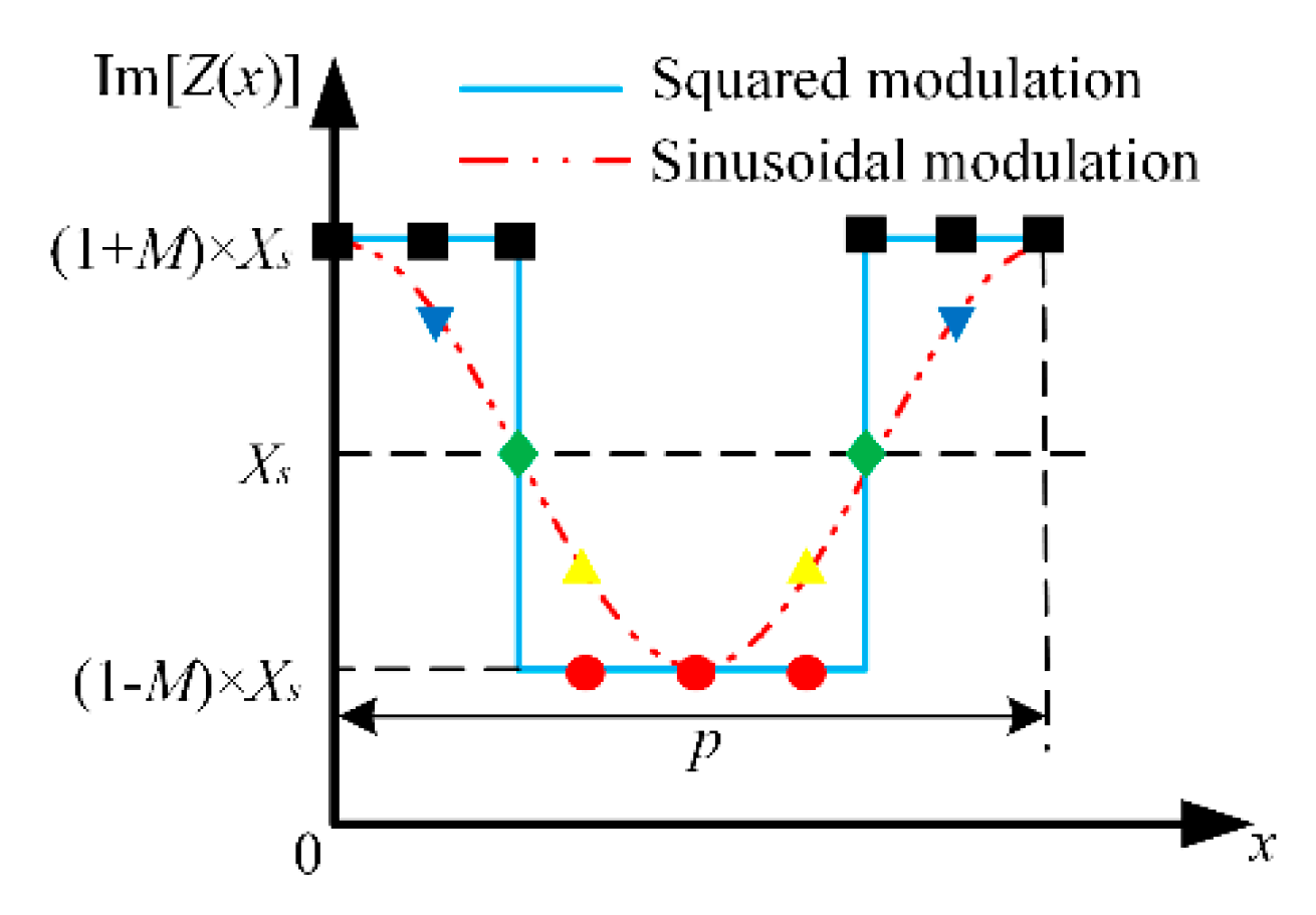
According to the Floquet theory, leaky-wave radiation can be generated by the periodically modulated structure. Therefore, for the construction of spatial distribution of surface impedance, squarely modulated reactance surface (SquMRS), instead of SinMRS, can be adopted to achieve the conversion from surface wave (electromagnetic wave that propagates along the interface between different media) to leaky-wave (electromagnetic wave that is coupled or transferred to a propagation medium outside the interface). The distributions of surface impedances along one period for SquMRS and SinMRS under different modulations, which have identical average value
Xs, modulation depth
M and modulation period
p, are shown in
Figure 1. Compared with SinMRS, the structure of SquMRS is much simpler since it needs fewer kinds of unit cells.
Assume the SquMRS is placed in the
xoy plane, while the direction of the propagation along the surface is the
x-axis, as shown in
Figure 2. For simplicity, only transverse magnetic (TM) polarization is discussed. The surface impedance distribution in one period exhibits a form:
where
Xs is the average value,
M is the modulation depth and
p is the modulation period.
Due to the periodic function of Equation (1), it can be expressed as a Fourier series expansion, and the impedance profile of squared modulation can be rewritten as:
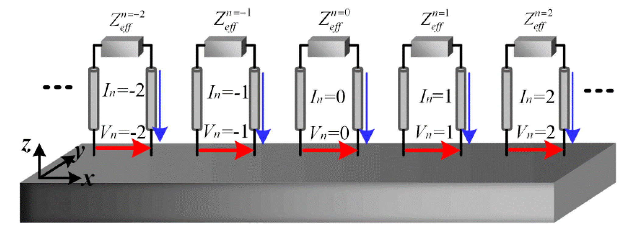
Here, an equivalent transmission lines model is established to analyze the dispersion characteristics, as shown in
Figure 2 and originally proposed in [
19]. An infinite number of independent transmission lines along the normal direction are coupled together at the impedance surface.
Zeff(n) =
Vn/
In is interpreted as the effective impedance of mode
n. The mode voltage
Vn and mode current
In are used to represent the field energy above the surface:
According to the Floquet theory, spatial harmonics can be generated by adjusting the modulation period
p:
in which
kx(n) and
βeff(n) are the wave number and phase constant of the
nth spatial harmonic,
αeff is the attenuation constant. It has to be noticed that the periodical modulation has few influences on the attenuation constant according to (5). Therefore, all space harmonics share an identical
αeff and possess different
βeff(n) for each mode
n. The effective impedance of mode
n Zeff(n) can be rewritten as:
where
η0 is the free-space wave impedance and
k0 is the free-space wavenumber. Using circuit theory, the effective impedance of mode
n = 0 can be derived as an infinite continued fraction:
Substituting the Equations (5) and (6) into Equation (7):
Due to the presence of an additional factor of 4
XSM/
π in each successive term, the continued fractions converge rapidly when the modulation depth
M has a small value. It is sufficient to yield the solution for
kx(0) to a high degree of accuracy by using (8) with only 3 modes considered, and then the effective phase constant
βeff(0) and attenuation constant
αeff of SquMRS can be calculated as:
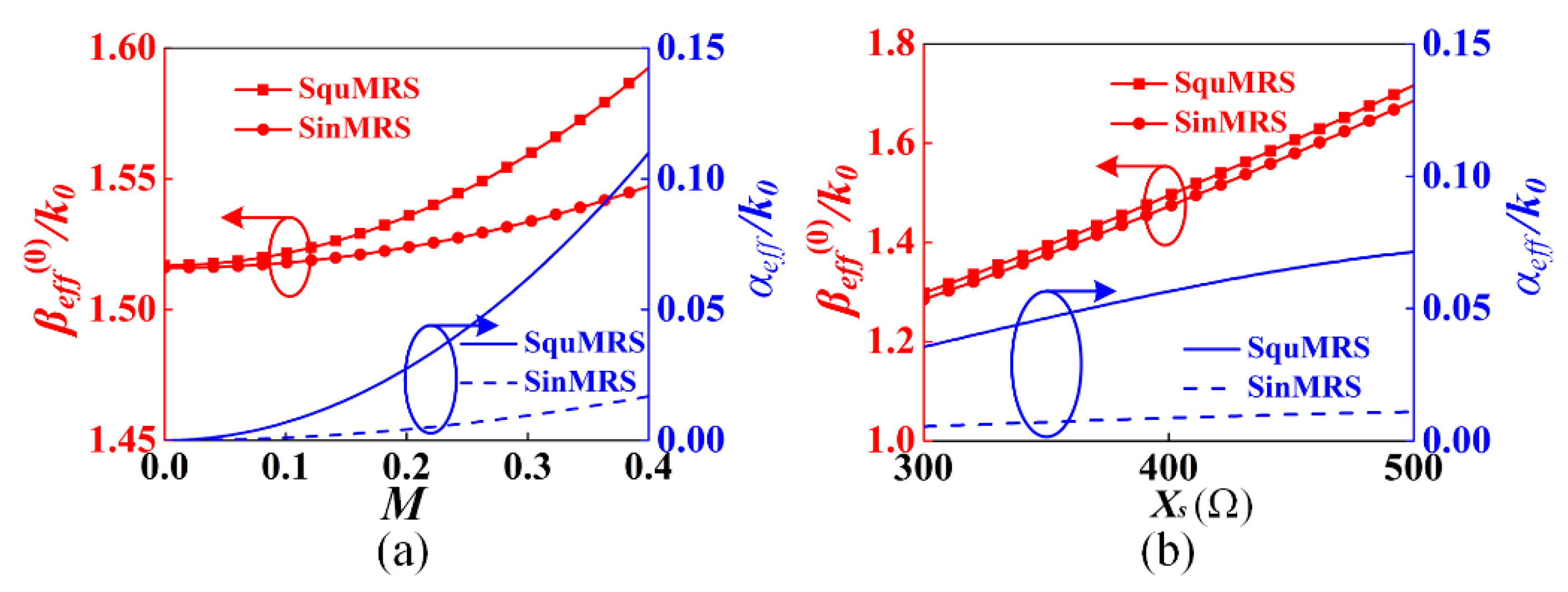
By using the equations mentioned above, the comparison between SinMRS and SquMRS is presented with parameters
Xs = 430 Ω and
p = 30 mm.
Figure 3a shows the relations between the dispersion characteristics and modulation depth
M at operating frequency of 8.5 GHz. It can be seen that both
βeff(0) and
αeff are increased as
M raises from 0 to 0.4, and the changes of SquMRS are more drastic than SinMRS. For both modulation methods, the variation of
βeff(0) is slight when the value of
M is less than 0.2. Meanwhile, SquMRS allows for more design flexibility to choose any required value of
αeff, since it has a larger variation range of the effective attenuation constant.
Figure 3b presents
βeff(0) and
αeff as a function of the average impedance
Xs with
M = 0.3. As can be seen,
βeff(0) is mainly affected by
Xs when
M is fixed. In conclusion, the values of
Xs,
M and
p should be modified to assure the independent control of attenuation constant and phase constant.
The spatial harmonics with
n ≤ 0 can be fast wave (
βeff(n) <
k0) by choosing suitable modulation period
p as
βeff(0) is larger than
k0. In this paper, the
n = −1 spatial harmonic is designed to be radiated. The radiation angle
θ can be derived as:
Therefore, SquMRS can generate the radiating beam with the same angle as SinMRS with a relatively simple structure.
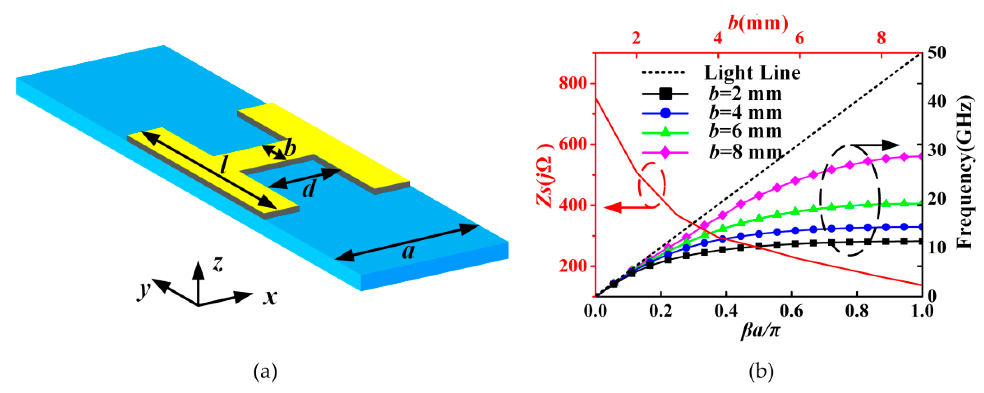
In order to construct the LWAs based on SquMRS for verification, the unit cell shown in
Figure 4a is proposed and analyzed in detail. The “H”-shaped unit cell was printed on a dielectric substrate with a relative permittivity of 2.65 and a thickness of 1 mm. The advantage of this unit cell is that its surface impedance can be easily modulated by changing the width of the central bar
b. The length of this unit cell
a was chosen to be 3 mm (0.085
λ0 at 8.5 GHz) to guarantee the sub-wavelength structure. Other dimensions of unit cell were
d = 1.1 mm,
l = 10 mm. The dispersion curves of the unit cell with different
b were obtained by using the commercial software CST Microwave Studio (Computer Simulation Technology TM, Darmstadt, Germany) [
21], as shown in
Figure 4b. The phase difference across the unit cell
βa was simulated by eigen mode solver under periodic boundary conditions [
22]. When
b decreases from 8 mm to 2 mm, the dispersion curves gradually bend away from the air line, giving rise to a much slower travelling wave. The results show that the phase constant
β of the dominant mode (
n = 0) becomes higher as
b decreases. Then, the surface impedance of the unit cell can be calculated as
. The relation between the surface impedance and
b is demonstrated in
Figure 4b. The surface impedance ranges from the minimum value of 137.5
jΩ to the maximum value of 752.3
jΩ at 8.5 GHz as
b decreases from 9 mm to 1 mm.
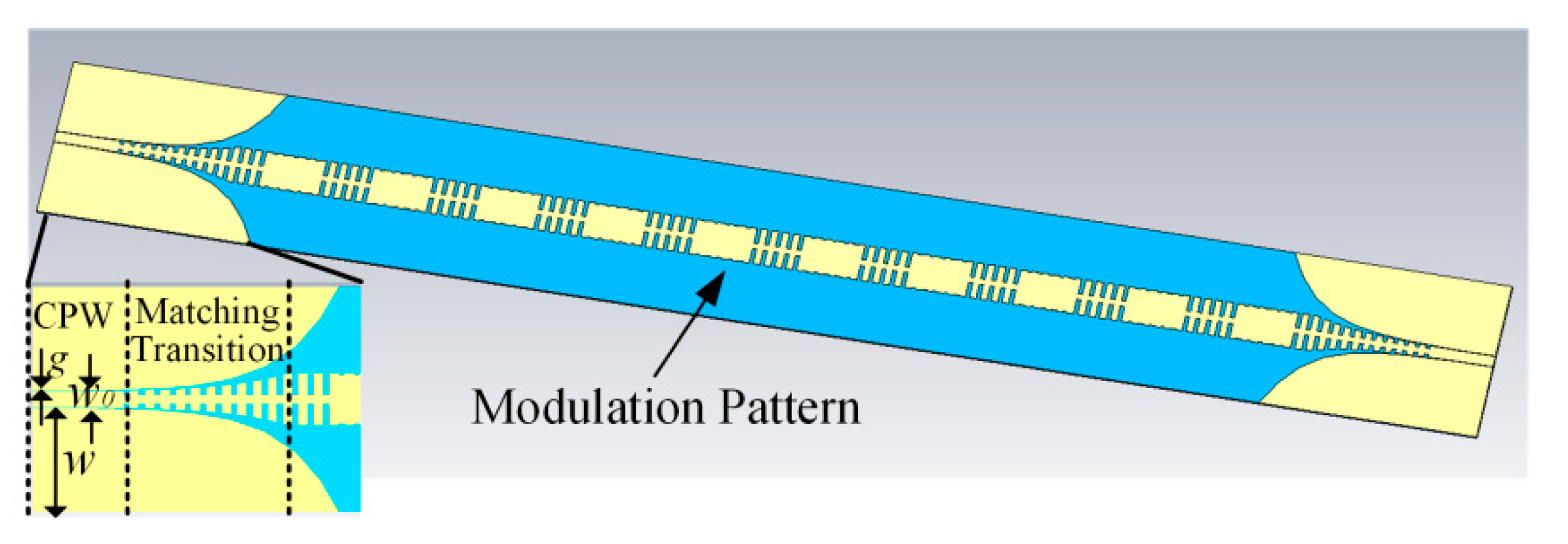
LWAs, based on these two modulation methods, were designed with a similar structure. The schematic of the LWA based on SquMRS is shown in
Figure 5, which consists of coplanar waveguides (CPWs), matching transitions and modulation pattern. The proposed LWAs were printed on dielectric substrates with a relative permittivity of 2.65 and a thickness of 1 mm. The dimensions of the CPWs shown in
Figure 5 are
w0 = 3 mm,
w = 20 mm and
g = 0.1 mm. In order to feed and receive energy, both ends of CPWs are designed to achieve 50 Ω impedance. The matching transition, which consists of a flaring ground and gradient grooves, provides a good matching of impedance and momentum between CPWs and modulation pattern [
23]. Therefore, a high-efficiency transmission is ensured by the matching transitions. The function of the modulation pattern is to generate the desired leaky-wave radiation by using the periodically modulated reactance surface, which is composed of 10 periods, and each period contains 10 unit cells. The distribution of surface impedance within one period is modulated as described in
Figure 1 with
Xs = 430 Ω and
p = 30 mm (10 unit cells per period). The desired radiation angle is set to be
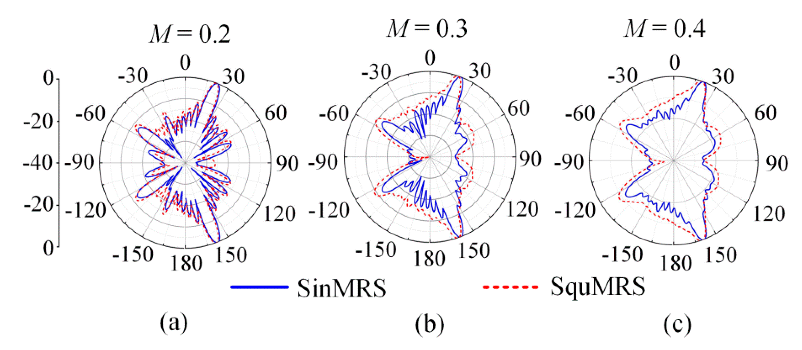
θ = 20° by using Equation (8). The simulated radiation patterns of different modulation methods at 8.5 GHz are shown in
Figure 6.
Table 1 reports the values of radiation angle
θ and beam width △
θ with different
M. For both modulation methods, the radiation angle changes a little when the modulation depth
M varies from 0.2 to 0.4 and the beam width increases with
M rising so that the feasibility of LWAs based on squared modulation is proved. It is worth noting that the broader beam is just a characteristic rather than an advantage of SquMRS.
3. Dual-Beam Leaky-Wave Antenna Implementation
A dual-beam LWA pointing at
θ1 = −30° (beam 1) and
θ2 = 18° (beam 2) was designed to operate at 8.5 GHz. In previous studies about producing multi-beams, the modulation pattern was divided into several regions, and each region provided a desired radiation beam [
24]. Usually, a monopole antenna was chosen as the feed source so that it was difficult to reduce the height of the antenna. In addition, a holographic synthesizing method, which translated any requested electromagnetic modulation of
β and
α along the antenna into the corresponding geometrical modulation, was used to produce multiple beams [
25]. Several previous designs, based on superposing multiple objective field patterns on the SinMRS, were proposed to produce multi-beams and achieve near-field focusing [
26,
27,
28]. In this work, a superposition method based on SquMRS was used to design a dual-beam LWA, due to the capability of flexible control of phase constant and attenuation constant. Unlike using
n = −1 and
n = −2 spatial harmonics to generate dual-beam (
βeff(−1) <
k0,
βeff(−2) <
k0) [
29,
30,
31], the produced two beams in this work are both excited by the
n = −1 space harmonic, and other space harmonics are all slow waves (only
βeff(−1) <
k0).
Assuming these two beams possess the identical
Xs and
M, the radiation angles are decided by the modulation period
p1 and
p2, respectively. The individual modulation patterns for each beam are added up at each unit of the proposed antenna [
22,
24]. According to the holographic antenna theory, once the interference pattern is recorded by the interaction between reference wave Ψ
ref and multi-beam radiation wave Ψ
rad on the modulated surface, the multiple beams can be reconstructed. The multi-beam radiation wave can be written as the sum of two individual beams: Ψ
rad = Ψ
rad(1) + Ψ
rad(2). The distribution of surface impedance is used to embody the whole surface interferogram:
where
f1(
x) and
f2(
x) are periodic functions of the desired two beams with the surface impedance coefficient
a1 and
a2 (
a1 +
a2 = 1), respectively. Therefore, the precondition of this superposing method is that two beams possess the identical
Xs and
M.
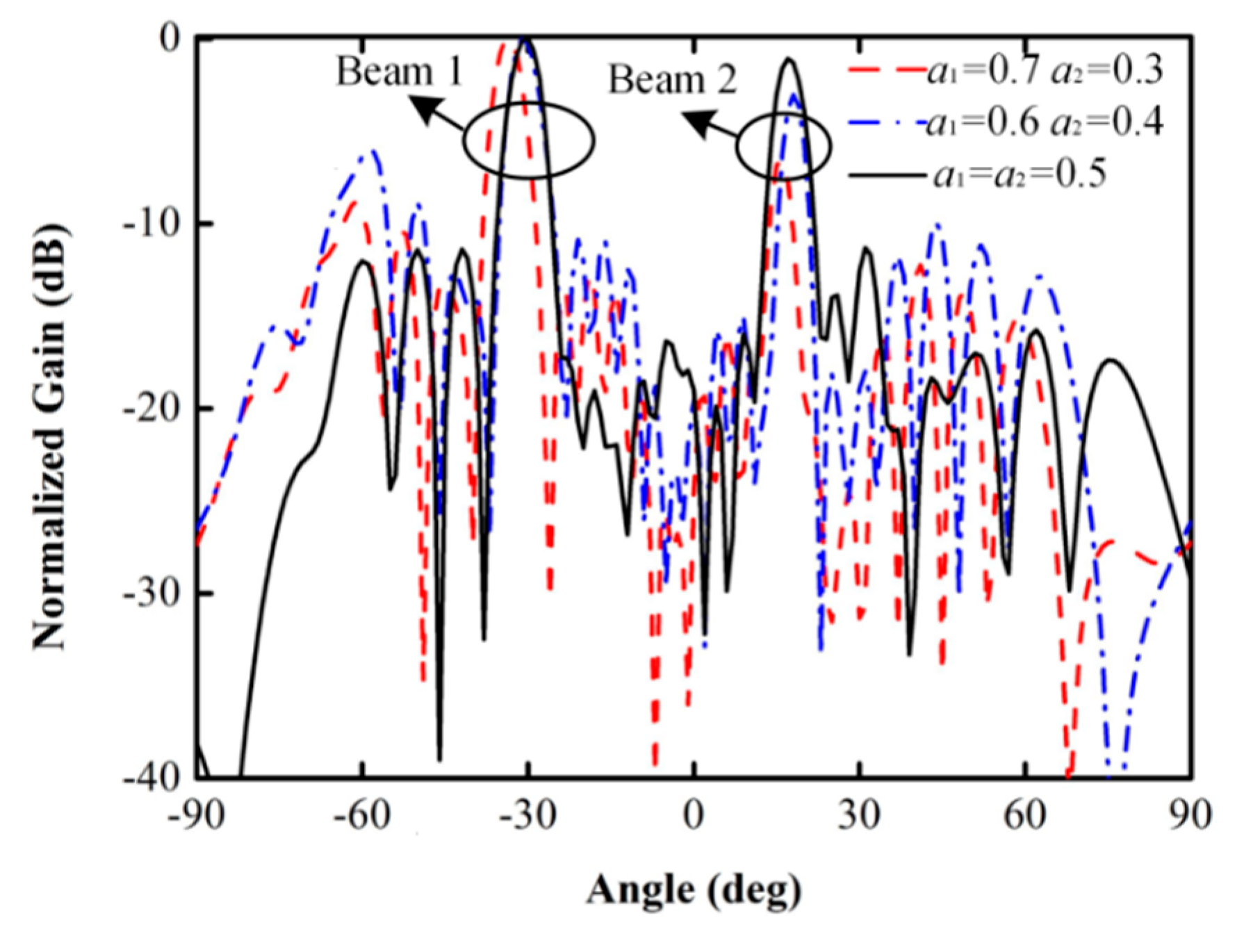
Figure 7 shows the simulated radiation patterns of the LWA with different surface impedance coefficients. In theory, two beams should obtain an identical gain when
a1 =
a2 = 0.5, but the simulated result shows that a gain difference (about 1 dB) existed. As
a1 raises to 0.6, the gain of beam 1 is 3 dB higher than the gain of beam 2. In these two cases, the changing of surface impedance coefficients has almost no effect on the radiation angles. Finally, the gain difference between two beams is about 6.5 dB when
a1 = 0.7,
a2 = 0.3. This means that this antenna can be considered as a single-beam antenna pointing at −34°, due to beam 2 actually being a side lobe (
θ2 = 16°). It can be concluded that the radiation power of each beam is related to the surface impedance coefficients. For the last case, the direction and gain of the radiation beams are obviously deviated from the theoretical values. These problems are not only caused by unequal surface impedance coefficients but also by the coupling between the two coexisted radiation patterns. In order to solve these problems, the surface impedance coefficients (
a1 and
a2) and modulation periods (
p1 and
p2) should be optimized from the initial values. The radiation efficiency from CST Microwave Studio simulation under these conditions is 84% (
a1 =
a2 = 0.5), 71% (
a1 = 0.6,
a2 = 0.4) and 48% (
a1 = 0.7,
a2 = 0.3). This means that the radiation efficiency is related to the balance of radiation energy from each beam.
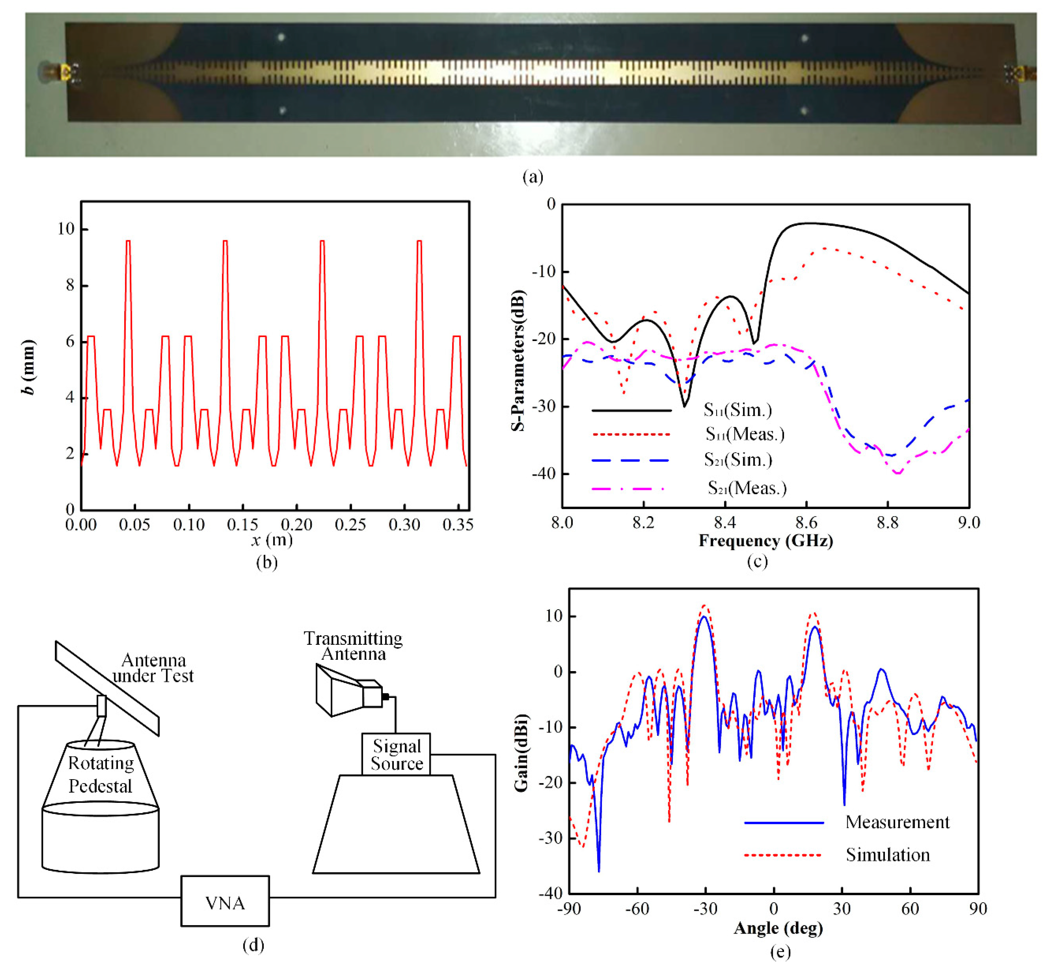
The prototype of the dual-beam LWA based on squared modulation was fabricated, as shown in
Figure 8a. The modulation pattern was designed with the parameters
Xs = 400 Ω,
M = 0.4,
p1 = 18 mm (6 unit cells per period) and
p2 = 30 mm (10 unit cells per period). Here
a1 =
a2 = 0.5 is applied to ensure the equal radiation energy of each beam. According to Equation (11), the modulation pattern with varying
b was designed to match the distribution of surface impedance, as shown in
Figure 8b. The measurement of S-parameters was conducted by using an Agilent N5227A microwave vector network analyzer (VNA, Agilent Technologies Inc., Santa Clara, CA, USA), and the simulated and measured results are presented in
Figure 8d. The reflection coefficient of the proposed antenna is almost below −10 dB in the frequency range of 8 GHz to 8.6 GHz, which means a good impedance match is provided. Meanwhile, S
21 keeps below −10 dB, indicating that little energy is transmitted to the output port. The far-field pattern was measured in the anechoic chamber with a linearly polarized horn antenna as the transmitting antenna, as shown in
Figure 8c. The measured gain of the antenna at 8.5 GHz is shown in
Figure 8e. The directions and beam widths of the measured main beams are in close agreement with the simulated patterns. The measured gains are 10 dBi and 8.2 dBi at
θ1 = −30° and
θ2 = 18°, respectively, and the radiation efficiency is about 83%. This may be caused by the additional loss brought by manufacturing error.


