Article

Ground Simulation Tests in Two-Dimensional Dynamic Acceleration Environment

1
Science and Technology on Electronic Test and Measurement Laboratory, North University of China, Taiyuan 030051, China
2
State Key Laboratory for Turbulence and Complex Systems, Department of Mechanics and Engineering Science, BIC-ESAT, College of Engineering, Peking University, Beijing 100871, China
*
Authors to whom correspondence should be addressed.
Appl. Sci. 2020, 10(3), 910; https://doi.org/10.3390/app10030910
Submission received: 25 November 2019 / Revised: 15 January 2020 / Accepted: 26 January 2020 / Published: 30 January 2020
(This article belongs to the Section Mechanical Engineering)

Abstract

:
Acceleration environment (AE) simulation tests have been widely applied in various areas such as aviation, space, environmental medicine, medical science, biomedicine, and materials. Most existing AE simulation test methods adopt impact and flight overload simulation separately, which cannot realize the synchronous controllable loading of two-dimensional (2-D) dynamic acceleration. In this paper, we propose and implement an AE simulation test method using an air-cannon-started compound centrifugal turntable. Specifically, our method emphasizes two processes, i.e., orderly transition from impact overload to steady-state overload and synchronous loading of 2-D dynamic AE. To further facilitate the method verification in AE, we develop a specialized simulation test platform. During field tests, axial acceleration of the unit being tested reached 20 g in 0.12 s at the launching stage and radial acceleration raised from zero g to 40 g in 0.5 s at the flight stage, achieving simulation of the 2-D dynamic AE. The obtained results show the effectiveness of the proposed simulation method, shedding light on updated design and control of impact simulation tests on the structures of crystal oscillator circuit, acceleration sensors, and related instruments.

Graphical Abstract

1. Introduction

Acceleration environment (AE) can generate accelerated environmental forces by means of simulation tests, which is used for performance testing and reliability experiments. AE has been widely applied in various areas such as aviation, space, environmental medicine [1], medical science [2], biomedicine [3], materials [4], and acceleration sensors [5]. The acceleration process of aircraft includes two stages: launch and maneuvering flight. The AE of aircraft is usually evaluated by the axial acceleration and the radial acceleration. The greater the axial acceleration is, the faster the speed change of the aircraft will be. The greater the radial acceleration is, the better the maneuverability of the aircraft will be. To perform ground-based tests of the acceleration sustaining ability of aircraft’s inertia device and aerospace materials and to verify the strength and reliability of the system, it is necessary to investigate ground simulation test methods of two-dimensional (2-D) dynamic AE.
An aircraft ground simulation test usually uses a centrifuge to emulate a sustained AE. Kvrgic et al. [6] studied the control algorithm of a centrifuge motion simulator for pilot training. The simulator could simulate acceleration forces that act on aircraft pilots through rotations about axes. Lin et al. [7] used accelerated centrifugal force to simulate G-forces during aerial combat, and studied stress-influence factors in the centrifugal training for military aircrews. But the centrifuge cannot realize the synchronous controllable loading of 2-D dynamic acceleration, so it is unable to simulate a flight AE. A composite system of a centrifuge and a test turntable can simulate the flight AE. Test turntable is an important equipment for research on inertia components and has been widely utilized in aerospace [8]. Guan et al. [9] used a double turntable centrifuge (DTC) to test rectification error due to the composite accelerations. The DTC was utilized to produce the constant acceleration and vibration simultaneously. However, the composite system cannot be started instantaneously, thereby failing to simulate an impact AE during the launch phase.
In general, a typical dynamic impact simulation device is composed of a Hopkinson bar, a drop tower, a centrifuge, and an air cannon. The live-fire tests include artillery launches and air drops. The acceleration amplitude, pulse width, and frequency characteristics generated by each acceleration simulation test method vary, so the application scope of each method is different. Through using impact loading tests to simulate the stress environments, the strain characteristics and impact resistances of materials can be studied. Douglas et al. [10] analyzed the performance of wafer-level chips by using board-level drop impacts to produce accelerations between 10,000 g to 30,000 g with multiple impacts at the impact point, and the acceleration amplitude and mounting clearance were varied. By modifying Taylor’s theory and optimizing the experimental models and parameter evaluation [11], Taylor’s rod experiments have achieved a high range of strain rates. Furthermore, Taylor’s rod experiments are simple, efficient, and reproducible, which become a common method of investigating material properties under high-strain-rate impact loads [12]. Brünig and Driemeier [13] proposed a specific thermo-hyperplastic constitutive model function to examine the performances of corresponding materials and numerically simulated the Taylor impact test. Shi et al. [14] designed a Hopkinson bar calibration device and studied a dynamic linear calibration method for high-g accelerometers. Using high-pressure gas as the power source and controlling the air pressure, an air cannon controlled the launch acceleration. Using the air cannon to assist the loading, it became possible to simulate a high acceleration load environment and the explosion impact environment, thereby allowing environmental testing on the structures of spacecraft and instrumentation.
In reality, the live-fire test usually requires high cost and a long cycle, which can hardly be repeated. The semi-physical simulation test can establish a similar environment in the laboratory to simulate an application environment of the aircraft. The existing AE simulation test methods generally adopt impact and flight overload simulation separately, which cannot realize the synchronous controllable loading of 2-D dynamic overload and cannot compare the real simulated impact and flight overload environment. Therefore, the objective of this paper is to propose a feasible 2-D dynamic AE simulation test method. Specifically, we focus on the key problems of loading in the impact overload environment, i.e., orderly transition from impact overload to steady-state overload and synchronous loading of 2-D dynamic AE. A specialized simulation test platform using an air cannon to start the compound centrifuge turntable is developed. Using the air cannon as the load propulsion system, the centrifuge provides a continuous AE. With vector distributions obtained by the single-axis turntable, synchronous loading of 2-D dynamic AE is implemented. This study contributes to research and development of extreme impact simulation tests on the structures of crystal oscillator circuits, acceleration sensors, and related instruments in dynamic AE.
The rest of the paper is organized as follows. In Section 2, the principle of the air-cannon-started compound centrifugal turntable simulation test method, the structure of the simulation device, and the simulation test process are introduced. In Section 3, the theoretical calculation, simulation, and testing of the simulation process in the impact overload environment are described. By controlling the pressure of the air cannon chamber, engaging the electromagnetic clutch, and adjusting the speed of the centrifuge, an orderly transition from the impact overload to the steady-state overload is achieved. In Section 4, by implementing a feed-forward proportional-integral-derivative (PID) control algorithm and the position–velocity–time (PVT) motion mode, controlling the angular displacement of the unit during testing, and applying a vector distribution of 2-D accelerations, synchronous loading of 2-D dynamic accelerations is achieved. In Section 5, a simulation test system is created to simulate 2-D AE. Finally, Section 6 gives concluding remarks.

2. Simulation Test Method with Air-Cannon-Started Compound Centrifugal Turntable

The requirements for the simulation tests are defined as follows. The acceleration process of the unit being tested includes two sequential stages: launch and maneuvering flight. After the system receives the launch order, the axial acceleration of the unit being tested must reach the set value within 0.2 s, and the radial acceleration of the unit being tested must be zero g during the launching stage. After the system receives the flight order, the radial acceleration of the unit should reach the set values within 0.5 s while the axial acceleration of the unit being tested remains unchanged during the flight stage.
The block diagram of the air-cannon-started compound centrifugal turntable simulation test system is illustrated in Figure 1. It mainly consists of a console, a speed control system, an electromagnetic clutch, a 2-D acceleration vector distribution system, an impact loading system, and a measurement system. The console is responsible for control and test of the entire system. The speed control system provides a continuous AE. The unit being tested and the vector distributor are installed on the main arm of the centrifuge. The centrifuge is controlled by the speed control system and the electromagnetic clutch. The 2-D acceleration vector distribution system is made up of a vector distribution controller, a driver, and a distributor. With a servo motor and the turntable used as the distributer, the resultant acceleration of the main arm of the centrifuge is distributed to the axial and radial directions of the unit being tested. The impact loading system consists of an impact loading controller, an impact loading driver, and an impact loader. An air cannon is employed as the impact loader to propel the main arm of the centrifuge for instantaneous acceleration. The measurement system measures the 2-D acceleration of the unit being tested and tests the working state of the unit being tested.

3. Simulation of Impact Overload Environment

The simulation test of the impact overload environment requires the axial acceleration of the unit being tested to reach the set value within 0.2 s, which is the typical characteristics of instantaneous and high impacts. When the unit being tested is driven by the centrifuge, its axial direction will point toward the axis of the arm. The normal and tangential directions of the arm are the axial and radial directions of the unit being tested. When the centrifuge accelerates, the normal acceleration of the arm increases, and the tangential acceleration fluctuates. When the centrifuge is running at a constant speed, the normal acceleration of the arm is constant and the tangential acceleration is zero g, which meet the requirements of the acceleration amplitude of the impact loading environment. However, the acceleration time lasts nearly 1 s, failing to meet the impact loading requirements. To tackle this problem, we propose a simulation method for the impact loading environment using an air cannon booster and a motor relay.

3.1. Impact Process of Air Cannon

The structure of the adopted air cannon is shown in Figure 2. The air cannon consists of a back-pressure chamber, a high-pressure chamber, a quick-opening chamber, a control valve, a piston, and a piston rod. Initially, the pressure in the quick-opening chamber is higher than the pressure in the high-pressure chamber. Thus, the high-pressure chamber is sealed by the piston, and the piston rod remains stationary. When the control valve is opened, the pressure in the quick-opening chamber drops sharply, and the piston moves to the right quickly. Under this circumstance, the high-pressure chamber is opened, the high pressure gas drives the piston rod to move to the left, thus the air cannon is fired.
The resultant force FP on the piston rod and arm and the thrust FArm on the arm are expressed as follows:
{ F P = s 1 P 1 s 2 P 2 F Arm = ( F P m P A 1 ) cos θ x = L t g θ θ ¨ = A 2 x ¨ = A 1
where s1 = 0.02 m2, which is the area of the piston; s2 = 0.0188 m2, which is the area of the piston minus the area of the piston rod; P1 denotes the air pressure in the high-pressure chamber during the launch; P2 denotes the air pressure in the back pressure chamber during the launch; A1 is the acceleration of the piston rod in the propulsion process; θ is the rotation angle of the arm in the propulsion process; mP = 44.7 kg, which is the equivalent load of the piston rod; L is the distance between the propulsion point and the axis of the arm; x is the displacement of the piston rod; and A2 is the tangential acceleration of the arm during the propulsion process.
The motion of the piston pushed by the air is assumed to follow an adiabatic expansion process of an ideal gas. The equation for the state of the gas is described below.
P 1 V 1 = M μ g R T
where V1 denotes the volume of the high-pressure chamber during the launch, M indicates the mass of the air, μg stands for the molar mass of the air, R is the gas constant, and T is the air temperature.
Based on the polytropic relationship of the gas in the high-pressure chamber during the compression and expansion process [15], the polytropic index of the air during the charging and discharging processes of the pneumatic system are set to 1.2. Thus, the pressures of the high-pressure chamber and the back-pressure chamber are expressed as follows:
{ P 1 = P 10 ( V 10 V 10 + x s 1 ) 1.2 P 2 = P 20 ( V 20 V 20 x s 2 ) 1.2
where P10 is the initial pressure of the high-pressure chamber at the time of launch, V10 = 0.0972 m3, which is the initial volume of the high-pressure chamber, P20 is the initial pressure of the back-pressure chamber at the time of launch, and V20 = 0.02827 m3, which is the initial volume of the back-pressure chamber.
Substituting Equation (3) into Equation (1) yields
{ F P = s 1 p 10 ( V 10 V 10 + x s 1 ) 1.2 s 2 p 20 ( V 20 V 20 x s 2 ) 1.2 F Arm = m Arm A 2 ,
where mArm = 45.7 kg, which is the effective load of the arm at the impact point, including the equivalent mass of the arm, the unit being tested, and the vector distributer.
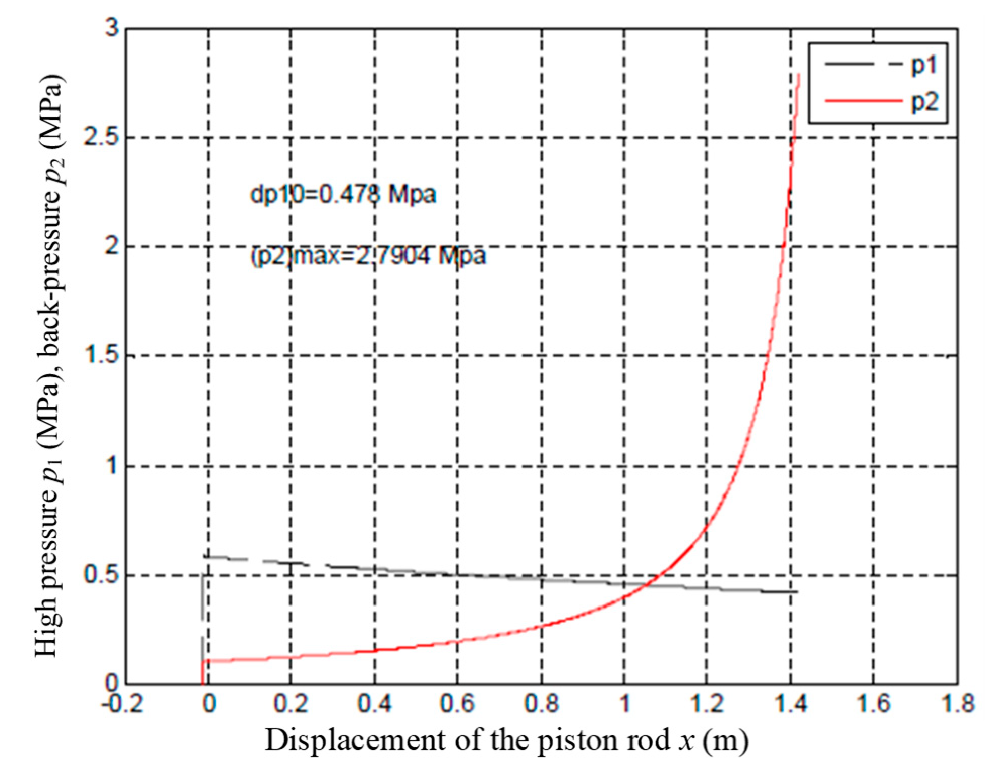
As shown in Equation (4), the acceleration of the arm during the impact is determined by the initial air pressures and volumes of the back-pressure and high-pressure chambers, the areas of the piston and piston rod, the displacement of the piston rod while it is propelled, the propulsion location, and the effective loads of the arm and piston. In the tests, only the initial pressures of the back-pressure and high-pressure chamber are variables, so the initial air pressure of the high-pressure and back-pressure chambers can be adjusted to obtain different launch accelerations. As the displacement of the piston rod increases, the thrust becomes increasingly small, and the piston rod can reverse directions. To avoid reverse collision between the arm and the recoiling air cannon, the piston rod and the arm are not placed at the same level. The collision end of the piston rod is machined into a pulley. The pulley rises before and falls after the collision. When simulating an impact overload environment of 10 g, the simulated air pressures of the high-pressure and back-pressure chambers versus the displacement of the piston rod can be obtained. Figure 3 plots the relationship between the pressure and the displacement of the piston rod.
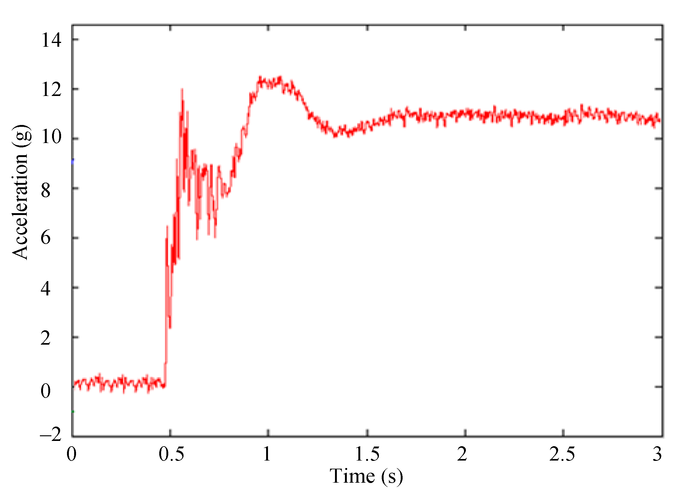
At the displacement of 0.5 m, the air cannon is fired, which is controlled by the air pressures of the high-pressure and back-pressure chambers. The acceleration of the pulley and the tangential acceleration of the arm are plotted in Figure 4. As can be observed, with an impact overload of 10 g, 2 ms after the air cannon launching, the accelerations peak 10.74 g and then drop rapidly. The accelerations remain between 6 and 7 g for about 30 ms, after which they decrease. The entire propulsion time lasts 119.5 ms. At the end of the launching, the tangential acceleration of the arm is zero g.

3.2. Clutch Engagement Process

During the simulation analysis, the air cannon pushes the arm. The starting time is very short, the acceleration amplitude and loading time meet the simulation test requirements of the impact overload environment. The air cannon propulsion duration is about 120 ms, but the acceleration rise time is only 2 ms. The duration of the peak is too short. To maintain the impact state, the clutch needs to be engaged and the motor needs to be relayed to power the arm rotation. If the relay is completed at the peak of the acceleration, the acceleration of the arm can be achieved.
The driving plate of the clutch is driven by the main control motor. The load on the driven plate includes the effective loads of the reducer, the rotating shaft, the arm, the vector distributor, and the unit being tested. The power transmission system of the centrifuge is shown in Figure 5.
The dynamic equation of the clutch transmission can be written as
{ J c ω ˙ c = T c T f J d ω ˙ d = T f T d ,
where Jc, ωc, and Tc are the moment of inertia, revolution speed, and output torque of the main control motor, respectively, Tf is the friction torque transmitted by the clutch, and Jd, ωd and Td are the effective moment of inertia, revolution speed, equivalent resistance torque of the driven plate, respectively.
When the clutch is completely disengaged, Tf = 0 Nm, and when the clutch is fully engaged, Tf = Tc = Td. The main operation process of the clutch in the test system varies from a fully engaged sliding friction state to a fully disengaged sliding friction state. The initial speed of the driven plate is zero rad/s. When the clutch is engaged, the speeds of the driven plate are shown in Figure 6.
At the beginning, the driven plate keeps stationary, the clutch is disengaged, and the motor is idling. Therefore, Td, Tf, and Tc are all zero Nm, and the motor’s speed ωc is a constant. When the clutch is engaged, the difference in the speeds of revolution becomes large. Tf is gradually increased, the revolution speed (ωd) of the driven plate increases, and the output torque (Tc) of the motor also increases. Because Tf is less than Tc, the motor accelerates. The difference in the speeds of revolution increases. Tf increases faster than Tc, and the driven plate accelerates. When Tf > Tc, the motor decelerates, the difference in the revolution speeds becomes increasingly small, and Tf gradually decreases. When Tf = Tc, the clutch is fully engaged, the motor drives the load to accelerate and stabilize after attaining the set revolution speed.
In the simulation tests, the arm is started by the air cannon. Ideally, the engagement process will be completed when the propelled acceleration reaches the maximum, and the tangential acceleration of the arm after launching will be equal to the set normal acceleration of the arm. Since the propulsion time is very short, ωd should be less than ωc, and the arm always accelerates during the engagement process. If the timing is missed, the engagement occurs too late, the arm decelerates, the impact acceleration is less than zero g, and the impact overload cannot be simulated. Therefore, it is necessary to select a suitable clutch and proper engagement timing. By controlling the pressures of the air cannon chambers and the revolution speed of the motor, the rapid transition between the impact overload and the continuous acceleration can be achieved.

3.3. Speed Control System Based on Active Disturbance Rejection Control

When the clutch is engaged, the output torque of the motor is increased rapidly, and the serious load disturbance is produced. In order to improve the precision of the speed control system, it becomes necessary to compensate for the disturbance. Active disturbance rejection control (ADRC) considers perturbations to the model and parameters and unmeasurable external disturbances as the total disturbance of the system. Based on the feedback control of the system error, the total disturbance is observed and corrected, which alleviates the conflict between the response speed and overshoot in the PID controls. ADRC does not rely on any precise mathematical model of a system, and it significantly improves the dynamic response characteristics of the controller through a proper nonlinear combination. The load disturbance can be estimated and compensated by a speed controller based on active disturbance rejection control (ADRC). Many researchers have studied the application of the speed controller based on ADRC. In order to improve pointing accuracy and rotation speed, Li et al. [16] designed the inner and outer loops of an ADRC for the antenna pointing control of a large flexible satellite system. Kang et al. [17] designed an idle speed controller based on ADRC to compensate for varying engine load and friction torque in passenger car diesel engines.
ADRC consists of three main components: a tracking differentiator (TD), an extended state observer (ESO), and a nonlinear state error feedback law (NSEFL). The TD arranges the transition process for the system and extracts the differential signal. ESO is the core of ADRC and can estimate the total disturbance of the system in real time and compensate for it. The outputs of the TD and ESO are compared to obtain the systematic error. Based on the error signal, the NSEFL produces a control strategy for the controlled object.
Based on the torque and motion equations of the three-phase asynchronous motor, the differential equation of the speed loop can be obtained as follows:
ω ˙ = ρ L m J L r ψ r i T s 1 J T L ,
where ω is the rotor speed, ρ is the number of the pole pairs of the motor, Lm is the stator-rotor mutual inductance, J is the system moment of inertia converted to the motor shaft, Lr is the rotor inductance, ψr is the rotor magnetic flux, iTs is the torque component of the stator current, and TL is the load torque.
There is a coupling term in Equation (6). When the load disturbance is considered, g3(t), the equation of state of the revolution speed becomes
{ ω ˙ = ρ L m J L r ψ r i T s + g 3 ( t ) y = ω g 3 ( t ) = T L J .
The corresponding second-order ESO is as follows:
{ ε 3 = ω ^ ω ω ^ ˙ = ρ L m J L r ψ r i T s + g ^ 3 ( t ) β 21 ε 3 g ^ ˙ 3 ( t ) = β 22 f a l ( ε 3 , a 3 , δ 3 ) ,
where α3, β21, β22, δ3 are four adjustable parameters, fal( ) is a nonlinear function, and it can be defined as follows:
f a l ( ε , α , δ ) = { | ε | α sgn ( ε ) , | ε | > δ ε δ α 1 , | ε | δ .
The nonlinear state error feedback control law is
{ e 3 = ω ω ^ i T s 0 = β 3 f a l ( e 3 , a 3 , δ 3 ) .
The control quantity iTs obtained by the nonlinear state error feedback control can be written as
i T s = i T s 0 J L r ρ L m ψ r g ^ 3 ( t ) .
Substituting Equation (11) into Equation (7) yields the following formula
{ ω ˙ = ρ L m J L r ψ r i T s 0 y = ω .
After the ADRC is adjusted, the coupling term is no longer included in the speed state equation and the total disturbance of the system is canceled. The structure of the speed outer loop ADRC system is illustrated in Figure 7.
Similarly, the first-order ADRC regulations for the excitation current loop and the torque current loop can also be obtained. The differential equation for the rotor flux is shown as follows:
ψ ˙ r = R r L r ψ r + L m R r L r i M s ,
where Rr is the rotor resistance and iMs is the excitation component of the stator current. Equation (13) does not contain a coupling term, and the rotor flux outer loop can be regulated by a PI controller. The first-order ADRC regulators are applied to the speed outer loop, the excitation current loop, and the torque current loop. Thus, the asynchronous motor speed control system based on the ADRC is designed.
Simulation and analysis of the speed control system based on ADRC are conducted. The parameters of the asynchronous motor are shown in Table 1. The appropriate parameters of the speed control system should be set before the simulation. The discretization time values are all set to 100 ms in this system. The regulator coefficients of the speed outer loop are: β21 = 1000, β22 = 16,000, a3 = 0.5, δ3 = 0.01, β3 = 10. The regulator coefficients of the excitation current loop are: β01 = 10,000, β02 = 120,000, a1 = 0.5, δ1 = 0.01, β1 = 100. The regulator coefficients of the torque current loop are: β11 = 10,000, β12 = 120,000, a2 = 0.5, δ2 = 0.01, β2 = 100. The regulator coefficients of the rotor flux outer loop are: Kp = 2, TI = 10.
In the simulation test of the system operation, the motor is started without a load. When the clutch is engaged, the load disturbance is produced, and the torque transmitted depends on the speed difference between the driving plate and the driven plate.
The load torque is shown as follows:
T f = J d α = 10 × 3 = 30   N m ,
where Jd = 10 Kgm2, which is the load moment of inertia, α = 3 rad/s2, which is the load angular acceleration.
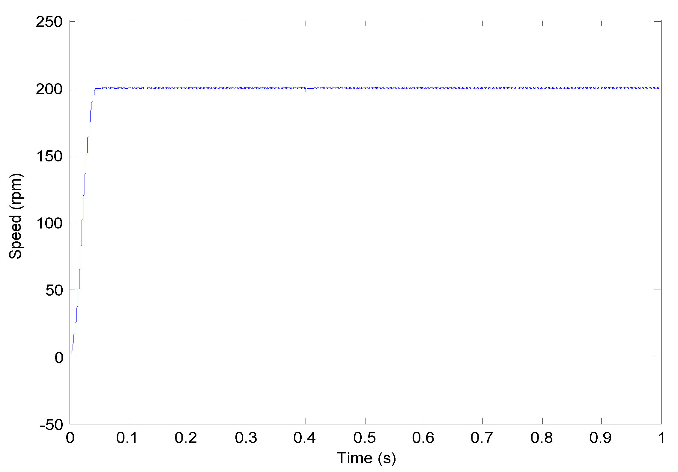
The set motor speed is 200 rpm, and the motor relay is set as 0.4 s with a load of 30 Nm added abruptly. The simulation results of the motor speed controlled by ADRC are shown in Figure 8 and Figure 9. As can be observed, the system response does not exhibit overshoot and the rise time is 0.037 s. When the load is suddenly applied at 0.4 s, the motor speed drops to 196.9 rpm. After 0.01 s, the speed quickly returns to a stable state. The load is driven by the air cannon before the clutch is engaged, and it is driven by the motor after the clutch is engaged. The load is rotating in the same direction as the motor and the speed difference between the load and the motor is small, so the change of the speed will become small and the recovery time will get short. Accompanied with the improved disturbance-rejection performance of the system, an orderly transition between the impact overload and steady-state overload can be achieved.

3.4. Loading Test of Impact Overload Environment

Both the air cannon firing and the electromagnetic clutch engagement commands are sent by the digital output module to the driving system controlled by the relay. The electromagnetic clutch is controlled by the carbon brush, and the air cannon is controlled by the electric solenoid valve. The response speeds of the two mechanisms are different.
The revolution speed of the arm is set as 105 rpm. After the air cannon is fired, the electromagnetic clutch is immediately relayed. The measured impact acceleration of the arm is shown in Figure 10. The steady-state normal acceleration of the arm is 11 g. The acceleration rise time is 74.56 ms. The loading time of the launch acceleration is 819 ms, which does not meet the simulation test requirements for the impact overload environment. The electromagnetic clutch has a longer response time than the solenoid valve, causing too long loading time. As can be measured, the electromagnetic clutch has a response time that is 250 ms slower than that of the electric solenoid valve. Therefore, the loading time of the impact acceleration can be regulated by adjusting the operating time sequence of the air cannon launch and the clutch engagement. After the clutch has been engaged for 250 ms, the air cannon is fired.
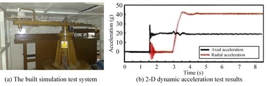
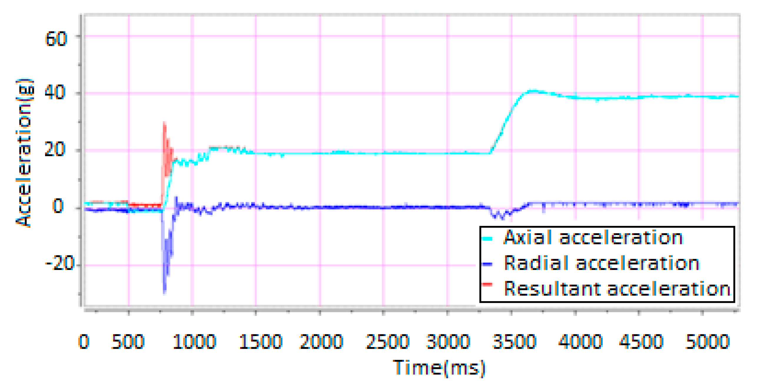
The unit being tested is fixed on the arm. The axial direction of the unit being tested points to the normal direction of the arm, and the radial direction of the unit being tested points to the tangential direction of the arm. So, the tangential acceleration of the arm is the radial acceleration of the unit, and the normal acceleration of the arm is the axial acceleration of the unit. The impact overload acceleration is set as 20 g. After 2.5 s of the air cannon being fired, the motor accelerates, and the axial acceleration of the unit being tested is set as 40 g. The 2-D acceleration test results of the unit being tested are shown in Figure 11. The air cannon propels the arm and produces a powerful impact. The radial acceleration of the unit being tested rises instantaneously. After the clutch is engaged, the motor drives the arm to rotate at a constant revolution speed, while the radial acceleration of the unit being tested is zero g. After 2.5 s, the motor is accelerated, and the axial acceleration of the unit being tested reaches 40 g.
As shown in Figure 11, the loading time of the impact overload acceleration is 120 ms, and the loading time of the flight overload acceleration is 335 ms, which satisfy the speed requirements of the axial acceleration of the unit being tested. However, during the acceleration of the arm, the tangential acceleration occurs, which does not meet the requirements of the simulation test for the radial acceleration of the unit being tested. Therefore, the vector shaft angle needs to be adjusted to track or decompose the resultant acceleration of the arm to achieve dynamically controllable loading of the radial acceleration of the unit being tested.

4. Synchronous Loading of 2-D Dynamic AE

As shown in Figure 11, the radial acceleration of the unit being tested is generated during the acceleration process. The shorter the acceleration duration is, the greater the radial acceleration amplitude will become. The radial acceleration is zero g at the stable and constant speed. The simulation test requires the axial and radial accelerations to be simultaneously applied to the unit being tested with controllable amplitudes. To this end, we propose a loading method of the centrifugal turntable AE based on the 2-D vector distribution. To implement the synchronous loading of the 2-D dynamic AE, when the centrifuge is accelerating, the vector axis rotation angle of the unit being tested is adjusted by the 2-D vector distributor. The tangential and normal accelerations generated by the centrifuge are then combined or decomposed to the axial direction and radial direction of the unit being tested. Therefore, the 2-D dynamic vector distribution for the accelerations can be obtained.

4.1. Centrifugal Turntable AE Loading System Based on 2-D Vector Distribution

The centrifugal turntable simulation test system includes an arm control subsystem, a 2-D vector distribution subsystem, and an acceleration test subsystem. The 2-D vector distribution subsystem and the acceleration test subsystem are mounted on the arm. The arm is driven by the variable-frequency adjustable-speed motor. Both the unit being tested and the accelerometer are fixed on the turntable. The turntable is driven by the servo motor. The acceleration of the unit being tested is fed back to the computer through the accelerometer. The control and test signals of the arm are transmitted through the conductive slip ring.
Based on the axial and radial acceleration requirements of the unit being tested, the combined acceleration of the arm can be calculated, and the rotation of the arm can be controlled. When the arm is accelerated, the servo motor controls the angular displacement of the turntable and the unit being tested, and the resultant acceleration of the arm can be decomposed along the axial and radial directions of the unit being tested to achieve the synchronous loading of the 2-D dynamic AE. If the axial direction of the unit being tested is along the direction of the resultant acceleration of the arm, the radial acceleration of the unit being tested is zero g, which simulates the impact overload environment. By decomposing the resultant acceleration of the arm in two dimensions and keeping the axial acceleration of the unit being tested constant, the flight overload environment can be simulated.

4.2. Control of Servo Tracking System for Angular Position of Unit Being Tested

Because of the elastic deformation of the transmission mechanism, the servo system of the axial angular position of the unit being tested is a very complicated high-order system. The servo motor drives the turntable through the conveyor belt, which negatively affects the dynamic response characteristics of the system. To suppress the interference caused by load changes, measures are required to form fully closed-loop control. In addition, control strategies and system rigidity both needs to be improved.
Feed-forward control is an open-loop control strategy for a certain disturbance parameter. It can make use of the characteristics of the object to improve the response speed of the system. However, it does not compensate for other disturbances. This problem can be solved by a closed-loop system using a compound control strategy with a combination of feed-forward and feedback control. The compound control strategy can not only reduce the dynamic influence of the disturbance on the controlled parameters by feed-forward control, but also reduce the steady error of the system by feedback control. Many researchers have studied the application of the compound control strategy based on feed-forward compensation in the position servo control system. To compensate for system nonlinearity, Sarkar et al. [18] applied feed-forward PID tracking controls to the design of an electro-hydraulic system. Fathi et al. [19] used a feed-forward PID compound controller to design a vision-based closed-loop laser solid freeform fabrication system.
As shown in Figure 12, the position compound controller uses a control strategy with speed/acceleration feed-forward compensation and integral separation PID. The speed/acceleration feed-forward compensation makes the controlled signals of the system insensitive to external disturbances and changes in the internal parameters of the system. The speed feed-forward controller can reduce the tracking error caused by damping. The acceleration feed-forward controller can reduce or eliminate the tracking error caused by the system inertia, thus improving the disturbance-rejection performance of the system. The parameters of the feed-forward PID controller includes a proportional coefficient (KP), derivative coefficient (Kd), integral coefficient (Ki), velocity feed-forward coefficient (Kvff), acceleration feed-forward coefficient (Kaff), and integral separation coefficient Kl. When the error is less than the set value, Kl = 1 and the integral loop nodes take effect; otherwise, Kl = 0 and the integral loop nodes do not take effect, the position error is no longer integrated, and the integral saturation is suppressed.
Consistent with Figure 12, the feed-forward compound PID control rules can be expressed as follows:
{ u 1 ( t ) = K v f f d c p ( t ) d t + K a f f d 2 c p ( t ) d t u 2 ( t ) = e ( t ) + K l K i e ( t ) d ( t ) u 3 ( t ) = K d d v ( t ) d t u ( t ) = K p ( u 1 ( t ) + u 2 ( t ) u 3 ( t ) ) ,
where u1(t) is the feed-forward output of the velocity and acceleration, u2(t) is the output of the position loop, u3(t) is the output of the velocity loop, u(t) is the output of the PID controller, cp(t) is the set position, v(t) is the actual angular speed of the servo motor, and e(t) is the error of the set position from the actual position.

4.3. Vector Axial Angular Displacement Motion Trajectory Planning

Hermite interpolation can be used to eliminate the issues that arise when the interpolation conditions contain derivatives. Therefore, the motions of the axial positions of the unit being tested are fitted using Hermite interpolation polynomials, which can guarantee that the displacement and velocity at the interpolation points are equal to those of the ideal motion. Each interpolation segment of the PVT motion mode is fitted with a two-point cubic Hermite interpolation polynomial. Only by specifying the position, velocity and running time of the segment and calculating the motion trajectory that meets the constraint conditions, the more compact control of the trajectory can be realized.
The angular displacement motions of the unit being tested shown in Figure 13 are divided into six segments. Three cubic Hermite interpolations in the different intervals are used to ensure the following point: the function values (displacement) and the first derivative values (velocity) at the interpolation points are exactly the same as the values of the motion trajectory. The velocity curve can be obtained by taking the derivative of the displacement curve. The cubic Hermite interpolation function corresponding to the first segment of the curve is calculated as follows:
{ P ( x ) = f ( x 0 ) h 0 ( x ) + f ( x 1 ) h 1 ( x ) + f ( x 0 ) H 0 ( x ) + f ( x 1 ) H 1 ( x ) h 0 ( x ) = ( 1 + 2 x x 0 x 1 x 0 ) ( x x 1 x 0 x 1 ) 2 h 1 ( x ) = ( 1 + 2 x x 1 x 0 x 1 ) ( x x 0 x 1 x 0 ) 2 H 0 ( x ) = ( x x 0 ) ( x x 1 x 0 x 1 ) 2 H 1 ( x ) = ( x x 1 ) ( x x 0 x 1 x 0 ) 2 x 0 = 0 , f ( x 0 ) = 0 , f ( x 0 ) = 0 x 1 = 1 , f ( x 1 ) = 6 , f ( x 1 ) = 5.2
where h0(x), h1(x), H0(x), and H1(x) are the interpolation basis functions.
The cubic Hermitian interpolation polynomial is as follows:
p ( x ) = 6 x 2 ( 3 2 x ) 5.2 x 2 ( x 1 ) = 17.2 x 3 + 23.2 x 2 , x [ 0 , 1 ]
Similarly, the cubic Hermitian interpolation polynomials corresponding to the other five segments can be obtained. The displacement curve after interpolation is depicted in Figure 14.
The cubic Hermitian interpolation must extract the first-order derivative of the motion curve at the interpolation point, which is smoother than the motion trajectory of the cubic spline interpolation and is suitable for S-shaped acceleration/deceleration controls of high-speed machining. As shown in Figure 11, the impact load is achieved in 0.12 s. The launch AE requires that the axial acceleration of the unit to be increased from zero g to 20 g in 0.12 s, and the radial acceleration is zero g. To simulate this AE, the initial position of the unit is vertical with the arm. During the acceleration, the servo motor controls the vector shaft rotation angle so that the axial direction of the unit is along the resultant acceleration direction of the arm. The shaft angular displacement-tracking curves based on the PVT mode are plotted in Figure 15. As can be observed, the unit is rotated 90° from the initial position in a pre-planned trajectory within 0.12 s. When the revolution speed of the arm reaches a steady state, the axial direction of the unit is along the normal direction of the arm, the axial acceleration is rω2, and the radial acceleration of the unit is maintained at rdω/dt = 0 g.

5. Verification Tests

Figure 16 shows a photograph of the built simulation test system. Mechanically, the impact and flight 2-D dynamic AE was simulated using an air cannon propulsion, a motor relay, and a vector axial angle tracking. The system has been applied to the performance test of aerospace components. The load time and the amplitude of the 2-D acceleration were set according to the performance index of the unit being tested. The axial acceleration of the impact overload was set as 20 g and the radial acceleration was zero g. The axial acceleration of the flight overload was maintained at 20 g, while the radial acceleration was increased from zero g to 40 g within 0.5 s.
The measured accelerations of the unit being tested with the synchronous loading are plotted in Figure 17. The simulation test process involved the following six steps.
(1) The unit being tested was fixed on the vector turntable and the initial position of the unit being tested was vertical with the arm. The axial direction of the unit being tested pointed to the tangential direction of the arm, and the radial direction of the unit being tested pointed to the normal direction of the arm.
(2) The electromagnetic clutch was disengaged, the asynchronous motor controlled based on ADRC accelerated to the set speed without the load, and the arm of the centrifuge remained stationary.
(3) The air cannon received the launch order and the simulation of the launch AE of the unit being tested began at 1.5 s. The air cannon pushed the centrifuge arm, starting the movement of the arm instantaneously, and then the impact overload was achieved. The radial acceleration of the unit being tested coincided with the tangential acceleration of the arm. Meanwhile the electromagnetic clutch was engaged, and the vector turntable was controlled by the servo motor based on the PVT mode. The orderly transition between the impact overload and the steady-state overload was achieved. The axial direction of the unit being tested was along the direction of the resultant acceleration of the arm. When the clutch was fully engaged, the arm was driven by the motor. The axial acceleration reached 20 g within 120 ms and the radial acceleration briefly reached a maximum of 10 g during the axial acceleration. The radial acceleration dropped sharply. As could be seen, the maximum of the radial acceleration of the unit being tested was 30 g without the synchronous loading in Figure 11, while it was 10 g with the synchronous loading in Figure 17. The maximum of the radial acceleration was greatly reduced, and this amount was safe and acceptable. It was verified that the acceleration could be effectively regulated by synchronous loading of 2-D dynamic acceleration.
(4) The unit being tested was rotated 90° and the axial direction of the unit being tested pointed to the pivot of the arm. The axial direction of the unit being tested pointed to the normal direction of the arm, and the radial direction of the unit being tested pointed to the tangential direction of the arm. The system ran stably and maintained the launch state. The radial acceleration of the unit was reduced to zero g, and the axial acceleration was unchanged.
(5) The unit being tested received the flight order and the simulation of the flight AE began at 3 s. The centrifuge accelerated again, and the servo motor controlled the rotation angle of the unit being tested. By decomposing the resultant acceleration of the arm in two dimensions and maintaining the axial acceleration of the unit being tested constant, synchronous loading of 2-D dynamic acceleration was realized. The radial acceleration of the unit was increased from zero g to 41.7 g in 0.5 s, and the axial acceleration was 21.67 g.
(6) The system ran stably and retained the flight state. After the system became stabilized, the axial acceleration of the unit was 20 g, and the radial acceleration was 40 g, satisfying the launch and flight simulation test requirements for the 2-D dynamic AEs.

6. Conclusions

Performing ground assessment of key components is impossible due to lack of 2-D dynamic AEs on missile on-board equipment, aviation materials, acceleration sensors, weapon safety systems, or other mechanical systems. To solve this problem, we have investigated simulation methods of the 2-D dynamic AEs. By combining theoretical analysis, computer simulations, and simulation tests of real objects, we propose and develop an air-cannon-started hybrid centrifugal turntable simulation test method and the simulation test system. Simulation results reveal that the proposed test method achieves the synchronous loading of the 2-D dynamic AE and is able to effectively simulate impact and flight in extreme AEs. The test principle and testbed can be potentially extended to a variety of extreme impact simulation tests in dynamic AEs.
In the future, we plan to improve and optimize the motion control and position tracking control strategies using the developed simulation testbed in dynamic AEs. To this end, it is necessary to examine new impact excitation methods to reduce energy losses, optimize the system structure, and increase the test accuracy to meet the requirements of higher and more stable simulation test performance.

Author Contributions

In this work, T.M., Y.Z. and H.Z. conceived and designed the test method; Y.Z. and H.Z. performed formal analysis; Y.W., Z.W. and H.Z. contributed data analysis; Y.Z. and J.Y. wrote the paper. All authors have read and agreed to the published version of the manuscript.

Funding

This work was supported by the National Natural Science Foundation of China under Grant 61573323 and Grant U1909206.

Conflicts of Interest

The authors declare no conflict of interest.

References

  1. Schroeder, M.J.; Phaniraj, V.; Koenig, S.C.; Latham, R.D.; Ewert, D.L. The role of arterial elastance in ventricular-arterial coupling in normal gravity and altered acceleration environments. Aviat. Space Environ. Med. 2001, 1, 1–7. [Google Scholar]
  2. Wada, T.; Konno, H.; Fujisawa, S.; Doi, S. Can passengers’ active head tilt decrease the severity of carsickness? Effect of head tilt on severity of motion sickness in a lateral acceleration environment. Hum. Factors 2012, 2, 226–234. [Google Scholar] [CrossRef] [PubMed] [Green Version]
  3. Zhu, X.R.; Deng, T.Z.; Pang, J.L.; Liu, B.; Ke, J. Effect of high positive acceleration (+Gz) environment on dental implant osseointegration: A preliminary animal study. Biomed. Environ. Sci. 2019, 9, 687–698. [Google Scholar]
  4. Muzaffar, K.; Kumar, P. Quality assessment and shelf life prediction of spray dried tamarind pulp powder in accelerated environment using two different packaging materials. J. Food Meas. Charact. 2017, 11, 265–271. [Google Scholar] [CrossRef]
  5. Dong, X.S.; Huang, Q.W.; Yang, S.H.; Huang, Y.; En, Y.F. Model and experiment of scale factor acceleration sensitivity of MEMS gyroscope in high acceleration environment. Microsyst. Technol. 2019, 25, 3097–3103. [Google Scholar] [CrossRef]
  6. Kvrgic, V.M.; Vidakovic, J.Z.; Lutovac, M.M.; Ferenc, G.Z.; Cvijanovic, V.B. A control algorithm for a centrifuge motion simulator. Robot. Comput. Integr. Manuf. 2014, 30, 399–412. [Google Scholar] [CrossRef]
  7. Lin, P.C.; Wang, J.H.; Li, S.C. Subjective stress factors in centrifuge training for military aircrews. Appl. Ergonom. 2012, 43, 658–663. [Google Scholar] [CrossRef] [PubMed]
  8. Liu, Q.S.; Xi, J.T. Case-based parametric design system for test turntable. Expert Syst. Appl. 2011, 38, 6508–6516. [Google Scholar] [CrossRef]
  9. Guan, W.; Meng, X.F.; Dong, X.M. Testing accelerometer rectification error caused by multidimensional composite inputs with double turntable centrifuge. Rev. Sci. Instrum. 2014, 12, 125003. [Google Scholar]
  10. Douglas, S.T.; Al-Bassyiouni, M.; Dasgupta, A. Experiment and simulation of board level drop tests with intentional board slap at high impact accelerations. IEEE Trans. Compon. Packag. Manuf. Technol. 2014, 4, 569–580. [Google Scholar] [CrossRef]
  11. Johnson, G.R.; Holmquist, T.J. Evaluation of cylinder-impact test data for constitutive model constants. J. Appl. Phys. 1988, 64, 3901–3910. [Google Scholar] [CrossRef]
  12. Rohr, I.; Nahme, H.; Thorns, K.; Anderson, C.E., Jr. Material characterisation and constitutive modelling of a tungsten-sintered alloy for a wide range of strain rates. Int. J. Impact Eng. 2008, 35, 811–819. [Google Scholar] [CrossRef] [Green Version]
  13. Brünig, M.; Driemeier, L. Numerical simulation of Taylor impact tests. Int. J. Plast. 2007, 23, 1979–2003. [Google Scholar] [CrossRef]
  14. Shi, Y.B.; Yang, Z.C.; Ma, Z.M.; Cao, H.L.; Zou, Z.W.; Zhi, D.; Chen, Y.X.; Feng, H.Z.; Liu, J. The development of a dual-warhead impact system for dynamic linearity measurement of a high-g micro-electro-mechanical-systems (MEMS) accelerometer. Sensors 2016, 16, 840. [Google Scholar] [CrossRef] [PubMed] [Green Version]
  15. Shin, Y.G. Estimation of instantaneous exhaust gas flow rate based on the assumption of a polytropic process. Proc. Inst. Mech. Eng. Part D 2001, 215, 637–643. [Google Scholar] [CrossRef]
  16. Li, S.L.; Yang, X.; Yang, D. Active disturbance rejection control for high pointing accuracy and rotation speed. Automatica 2009, 45, 1854–1860. [Google Scholar] [CrossRef]
  17. Kang, E.; Hong, S.; Sunwoo, M. Idle speed controller based on active disturbance rejection control in diesel engines. Int. J. Automot. Technol. 2016, 6, 937–945. [Google Scholar] [CrossRef]
  18. Sarkar, B.K.; Mandal, P.; Saha, R.; Mookherjee, S.; Sanyal, D. GA-optimized feedforward-PID tracking control for a rugged electrohydraulic system design. ISA Trans. 2013, 52, 853–861. [Google Scholar] [CrossRef] [PubMed]
  19. Fathi, A.; Khajepour, A.; Toyserkani, E.; Durali, M. Clad height control in laser solid freeform fabrication using a feedforward PID controller. Int. J. Adv. Manuf. Technol. 2007, 35, 280–292. [Google Scholar] [CrossRef]
Figure 1. Air-cannon-started compound centrifugal turntable simulation test system.
Applsci 10 00910 g001
Figure 2. Schematic diagram of air cannon structure.
Applsci 10 00910 g002
Figure 3. Relationship between the pressure and the displacement of the piston rod at the impact overload of 10 g.
Applsci 10 00910 g003
Figure 4. Measured acceleration of the pulley and the tangential acceleration of the arm at the impact overload of 10 g.
Applsci 10 00910 g004
Figure 5. Schematic diagram of the power transmission system of the centrifuge.
Applsci 10 00910 g005
Figure 6. Plots of the revolution speeds when the clutch is engaged.
Applsci 10 00910 g006
Figure 7. Structure of the active disturbance rejection system of the speed outer loop.
Applsci 10 00910 g007
Figure 8. Simulation of the revolution speeds of the motor using active disturbance rejection control (ADRC).
Applsci 10 00910 g008
Figure 9. Zoomed-in revolution speeds of the motor using ADRC.
Applsci 10 00910 g009
Figure 10. Impact acceleration test results for the arm.
Applsci 10 00910 g010
Figure 11. 2-D acceleration test results for the unit being tested.
Applsci 10 00910 g011
Figure 12. Position compound controller based on feed-forward proportional-integral-derivative (PID).
Applsci 10 00910 g012
Figure 13. Angular displacement curve of the unit being tested.
Applsci 10 00910 g013
Figure 14. Displacement curve produced by the cubic Hermite interpolation.
Applsci 10 00910 g014
Figure 15. Plots of the shaft angular displacement tracking based on the position–velocity–time (PVT) mode.
Applsci 10 00910 g015
Figure 16. The built simulation test system.
Applsci 10 00910 g016
Figure 17. 2-D dynamic acceleration test results of the unit with the synchronous loading.
Applsci 10 00910 g017
Table 1. Parameters of the asynchronous motor.
ParameterValue
Polar logarithm (pn)2
Rated voltage (Vn) [V]380
Stator resistance (Rs) [Ω]0.68
Rotor resistance (Rr) [Ω]0.45
Stator leakage inductance (Lis) [H]0.0042
Rotor leakage inductance (Lir) [H]0.0042
Mutual inductance between stator and rotor (Lm) [H]0.01486
Motor inertia (Jm) [kg·m2]0.05

