1. Introduction
Holography can fully reconstruct 3D scenes with all phase and amplitude information. Traditional optical holography can record very high-resolution holograms with lasers as illumination, but a stable optical platform is needed, as well as other optical devices. In contrast to optical holography, the 3D information can be coded into a computer-generated hologram for holographic 3D display [
1,
2]. Many efforts for dynamic holographic displays have been made for monochrome or color displays using lasers or light emitting diodes (LEDs) as illumination [
3,
4,
5,
6,
7,
8]. The progress on dynamic holographic 3D displays, however, still have proven difficult due to the constraints of limited bandwidth of the current available spatial light modulator (SLM) and huge amount of calculations.
High-resolution holograms such as rainbow holograms and Fresnel holograms are applicable for 3D advertising and packaging because of the emergence of holographic printing technology [
9,
10,
11,
12,
13,
14]. The biggest challenge for high-resolution holography is the huge amount of computation. Multiple algorithms such as point cloud-based, layer-based, and triangular mesh-based algorithms, as well as holographic stereogram methods have been proposed [
15,
16,
17,
18]. However, those methods are not effective for reducing the calculation burden for high-resolution holograms. We have proposed frequency fusing methods similar to holographic stereograms for full-parallax image hologram [
11] and color rainbow hologram [
10] calculations with high efficiency, but the sizes of the calculated holograms are limited by the RAM (Random Access Memory) of the computer. Rectangular tiling algorithms have been proposed for high-resolution hologram calculations free of limitations from computer RAM [
19,
20]. Taking Reference [
19] as an example, each rectangular tile is calculated by using the 3D object data within the field of view (FOV) of this tile using the point cloud-based method. A full-parallax hologram with a resolution of 20,000 × 20,000 can take up to 32.9 h. Another rectangular tiling-based algorithm is integral holography, which is the combination of integral imaging 3D displays and holography [
21,
22,
23,
24]. In this method, each element of the light field image (EI) rendered from a micro-lens array or pinhole array is firstly fast Fourier transformed (FFT) as the complex amplitude of each elemental hologram, also called a hogel. Then the hogel is calculated by the interference of the complex amplitude with a reference wave. However, the calculation of complex amplitude using FFT is time consuming, especially for large-scale high-resolution hologram calculation.
In order to reduce the computational time of the high-resolution hologram, and inspired by integral holography, a simple and fast calculation method without using FFT is proposed. A pinhole array is set behind the holographic plane for rendering EIs. Each EI located on the holographic plane is multiplied with a divergent spherical wave, which is regarded as the complex amplitude of this hogel. Additionally, a reference wave is interfered with complex amplitude for this hogel calculation. Parallel acceleration is used to speed up the calculation because the calculation of each hogel is independent. A full parallax high-resolution hologram with a resolution of 200,000 × 200,000 is calculated only within 8 min. The validity of this proposed method is approved by optical reconstructions.
2. Methods
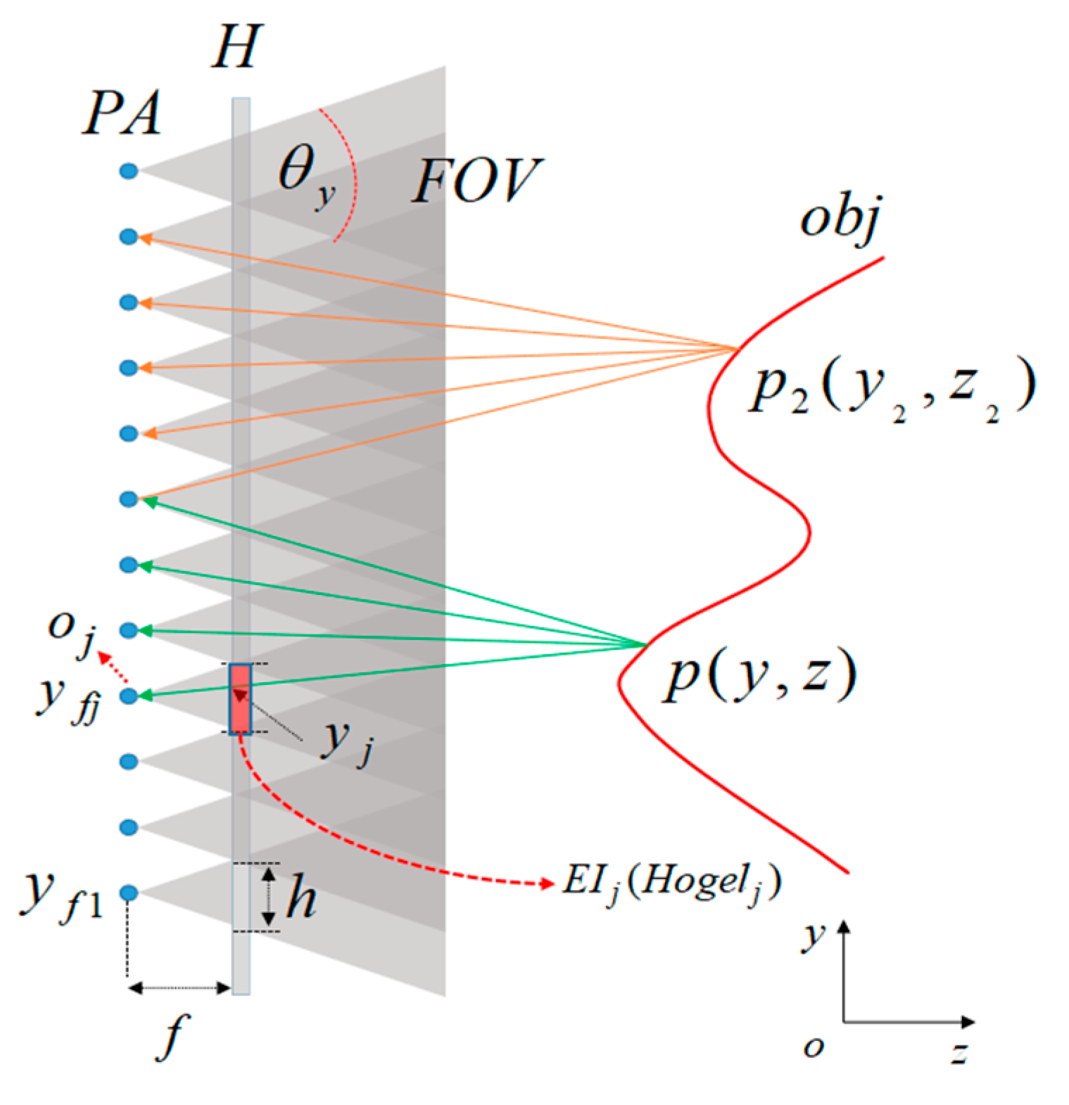
Figure 1 shows the rendering of EIs with a pinhole array for hologram calculation. PA is a pinhole array behind the holographic plane H. The distance between PA and H is
f. Obj is a 3D object in space, and
and
are two object points of obj. The EI is an image rendered from the 3D object to a pinhole. The
, for example, is rendered from the pinhole
by calculating the projected image from all 3D objects to
within the opening angle from the pinhole to this EI. This
is coded into the
. In this situation, the size of EI is the same as the size of hogel, as well as their coordinates. The EI on the holographic plane has a width of h, and the FOV is dependent on the opening angle
of the EI to the corresponding pinhole in the
y direction. Each EI is closely adjacent to other EIs. The coordinate of
j-th pinhole
is
, and the projections of point
and
within the FOV to each pinhole are demonstrated. The intersections of projection lines to each pinhole on the holographic plane are coordinates of the projected points of EI. For example, in
Figure 1,
is the coordinate of EI in the
y direction, which can be expressed as follows:
This calculation can also be applied to the
x direction, and the
of the projected EI can be expressed as follows:
where
is the coordinate of the object point P in the 3D coordinate system, and
is the coordinate of EI
on the holographic plane. The coordinate of the
pinhole is
. The
EI can be expressed as follows:
where
is the amplitude of object point
and
is the index of the EI. The phase of this hogel on the holographic plane is a phase of the sphere wave from the pinhole to the hogel, which can be expressed as follows:
The complex amplitude of the object wave-front corresponding to each hogel is found by multiplying Equation (3) by a divergent sphere wave with the phase illustrated in Equation (4). This concept is simple and straightforward. From the view of the local area, the local amplitude and spherical wave control the amplitude and propagation direction of this small beamlet.
Assuming that the reference light is a plane wave, and the angle between the plane wave in the
y direction and the
z axis is
, the off-axis amplitude type
hogel can be expressed as follows:
After the parameters of the PA and FOV of the hologram, as well as other necessary parameters are provided, each hogel can be calculated independently. All the hogels form the final high-resolution hologram.
3. Experiment and Results
The pixel pitch
of the hologram is 0.318 μm, which is determined by our holographic printer [
9,
10,
11]. This principle of the home-made holographic printer is similar to the holographic printer introduced in Reference [
12], but the light source in our holographic printer is a blue LED with a center wavelength of 365 nm rather than a laser. The maximum frequency that the holographic printer can support is
line/mm. Printing holograms at the highest resolution requires extremely stability for the printing system. In practical usage, almost half of the highest resolution is used for hologram design. In the experiment, the diffraction angles of the FOV in the
x and
y directions are set as
is 48°, and
is 20°, respectively. The angle of the reference wave in the
y direction and
z axis is set as 22°, assuming the wavelength is 632 nm. Therefore, the max frequency is
line/mm in the
x direction, and the max frequency is
line/mm in the
y direction, respectively. This is assuming that the distance between the pinhole and holographic plane is
f = 1 mm. In this situation, the width and length of each hogel or EI is
mm and
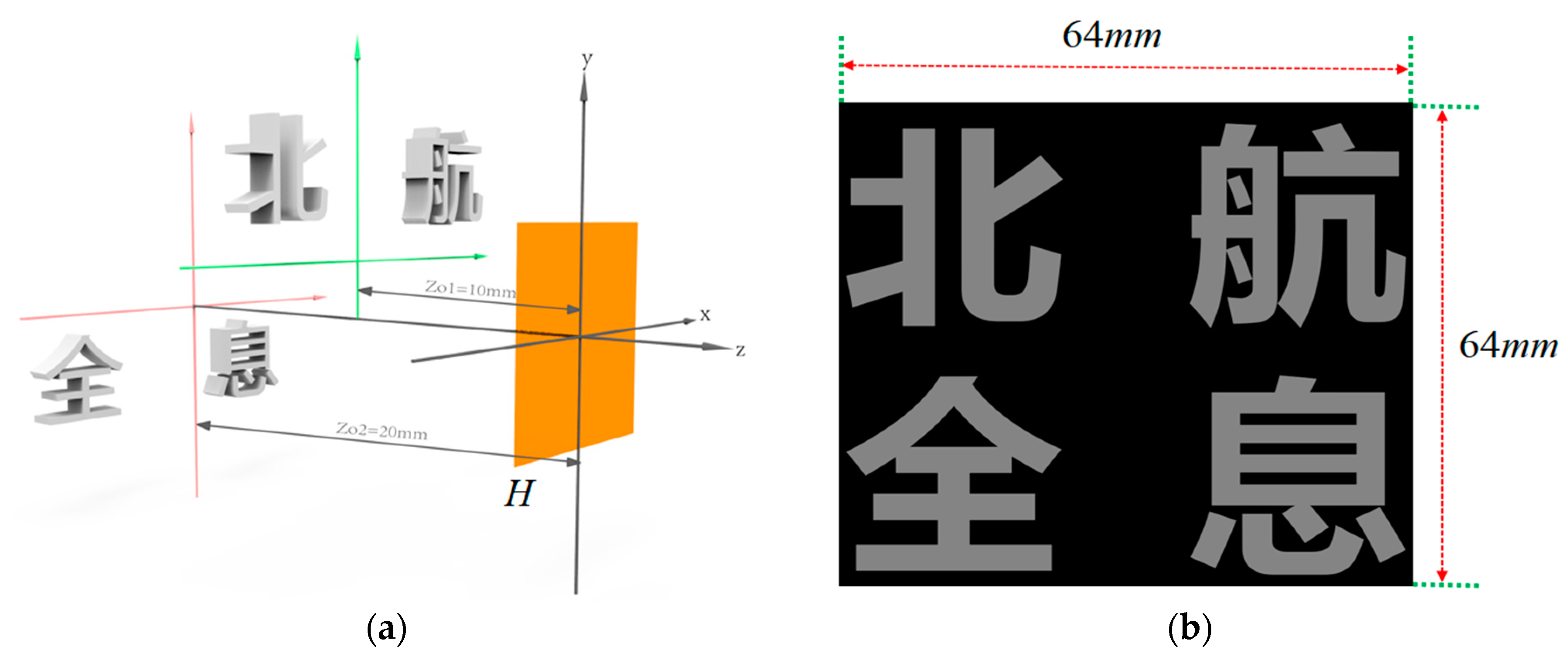
mm. The geometric relationship of the hologram calculation using a 3D point cloud model with two layers is shown in
Figure 2a. The first layer has a distance of 10 mm while the second layer has a distance of 20 mm from the holographic plane H. The two-layer Chinese characters are shifted in the vertical direction to guarantee not to overlap when they are viewed from the front view for simplicity. The 3D model has a size of 64 × 64 × 10 mm (W × H × D) with 984K object points. The front view of the 3D model is shown in
Figure 2b.
In the rendering of the EIs, the sampling intervals for both
x and
y directions are set as 4 μm and the resolution of each EI is 222 × 88 pixels. The parameters for hologram calculation are summarized in
Table 1. In the proposed method, the size of the EI is the same as the size of the hogel, but the sampling intervals are different. After we get an EI from the 3D model, this EI is firstly interpolated to a new EI with the same resolution as the hogel. The interpolated EI is used for hologram calculation according to Equation (5). In the calculation, after the size of the EI is determined, the number of the EI is calculated by
and
. The resolution 200K × 200K of the hologram is also an approximation of the physical size of 63.6 × 63.6 mm. The approximation is possible because missing a little bit of data on the outer edge of the hologram does not affect the 3D display.
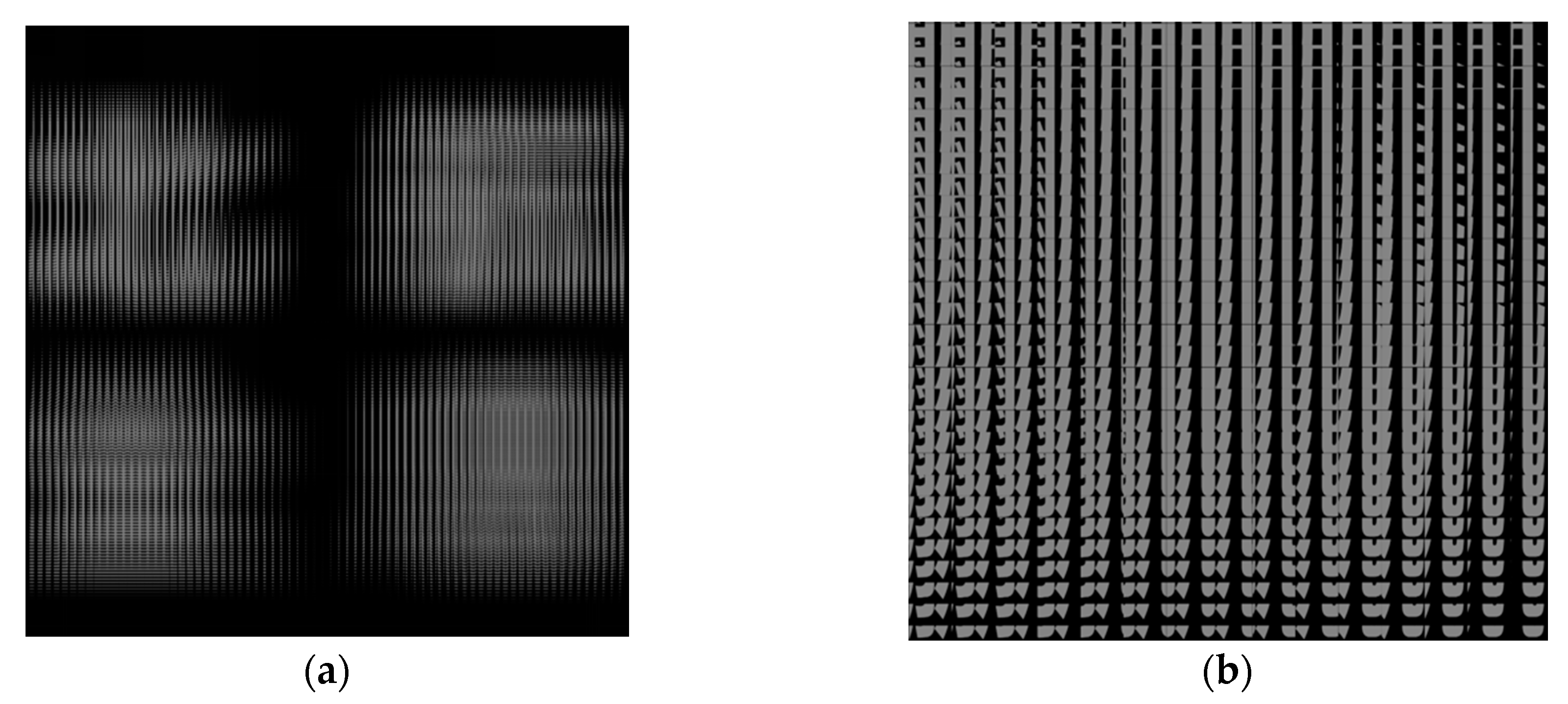
Figure 3a shows the rendered light field image, which contains all EIs rendered from the 3D model.
Figure 3b is an enlarged part of the light field image. The light field image almost has a resolution of 16K × 16K, which is much higher than the resolution of current commercially available display panels. The high-resolution light field image and high-resolution hologram guarantee high imaging quality and a large FOV of reconstructed 3D images.
Because of the independent property of calculations for each hogel in the proposed method, “parfor” in MATLAB is used for parallel acceleration. MATLAB 2015b and a laptop (i7-9750HQ CPU, 16G RAM and 1024G SSD) were used for hologram calculations. Six CPU cores were used in the hologram calculation. The computational time was about 8 min for the calculation of this hologram, including the time used for EI rendering. The hologram was printed with our home-made holographic printer from the Institute of Information Optics, Zhejiang Normal University, in about 4.5 h.
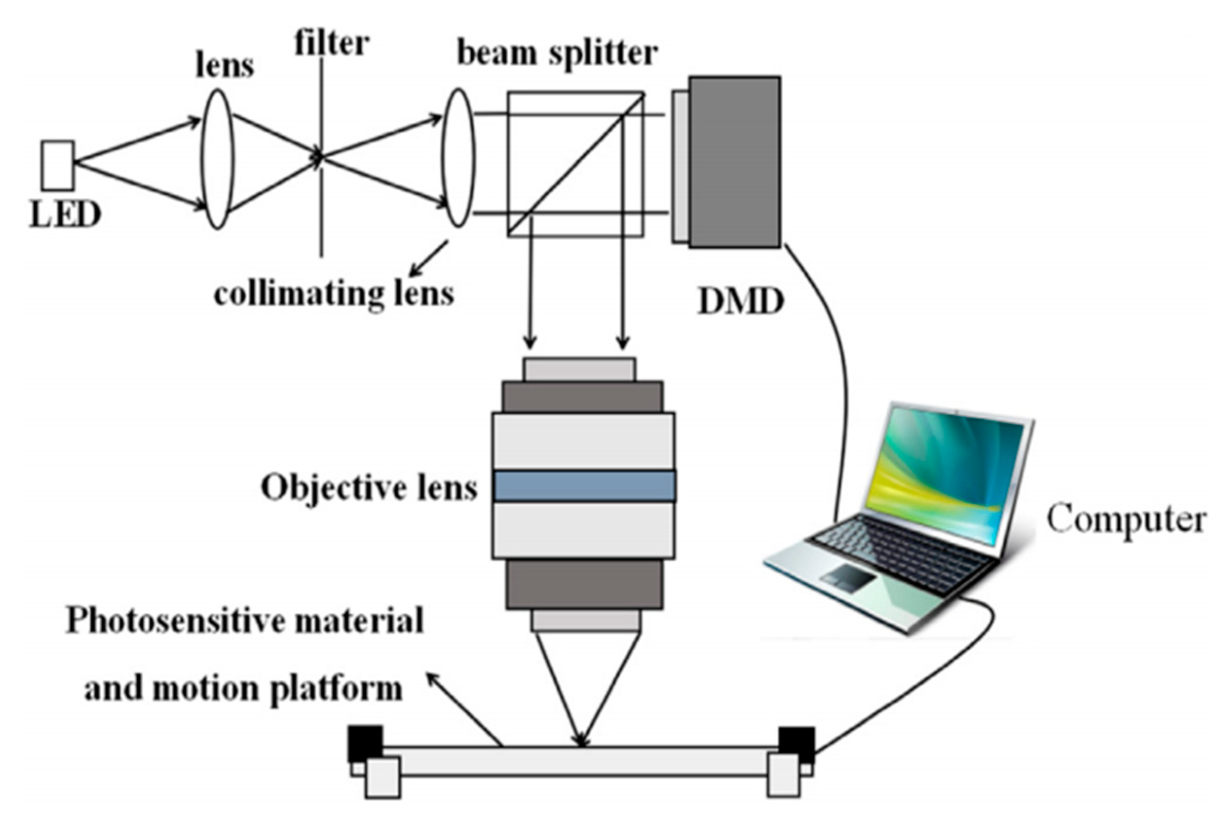
The overall diagram of the holographic printer is shown in
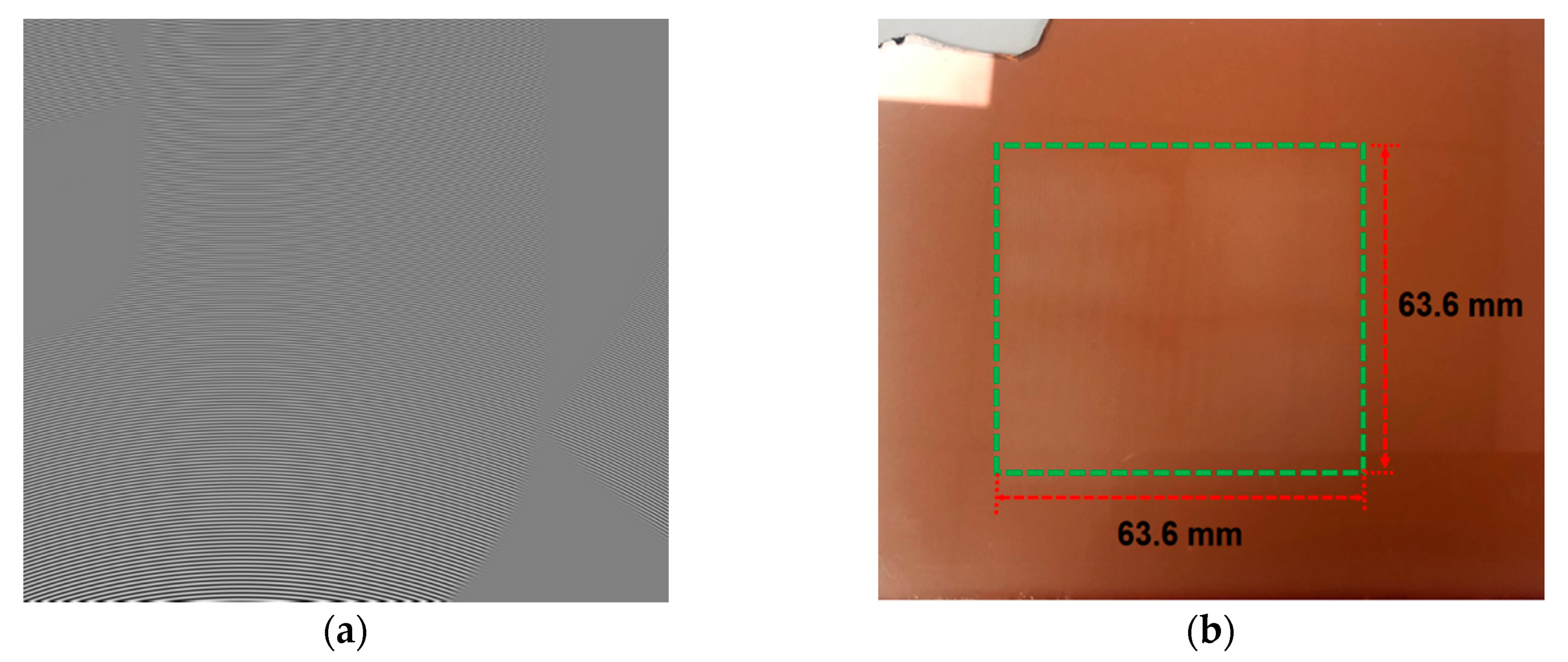
Figure 4. The light from the LED is filtered and collimated to illuminate the digital micro mirror (DMD) with a resolution of 1024 × 768 pixels. A small portion of the calculated hologram with a resolution of 600 × 600 pixels is first zero padded to the same resolution as the DMD and then loaded into the DMD for display. The modulated light from the DMD is imaged on the photosensitive material through the objective lens, and this small portion of the hologram is printed. Controlled by the computer, the motion platform is moved to the next position to print the next hologram section. With this holographic printer, the maximum size (a 200 × 200 mm hologram with pixel pitch of 0.318 μm) can be printed on a photoresist plate. The part of the calculated hologram and the printed hologram are shown in
Figure 5a,b, respectively.
In the reconstruction, a halogen lamp available in our lab is used as illumination source. The reconstruction of the hologram is demonstrated in
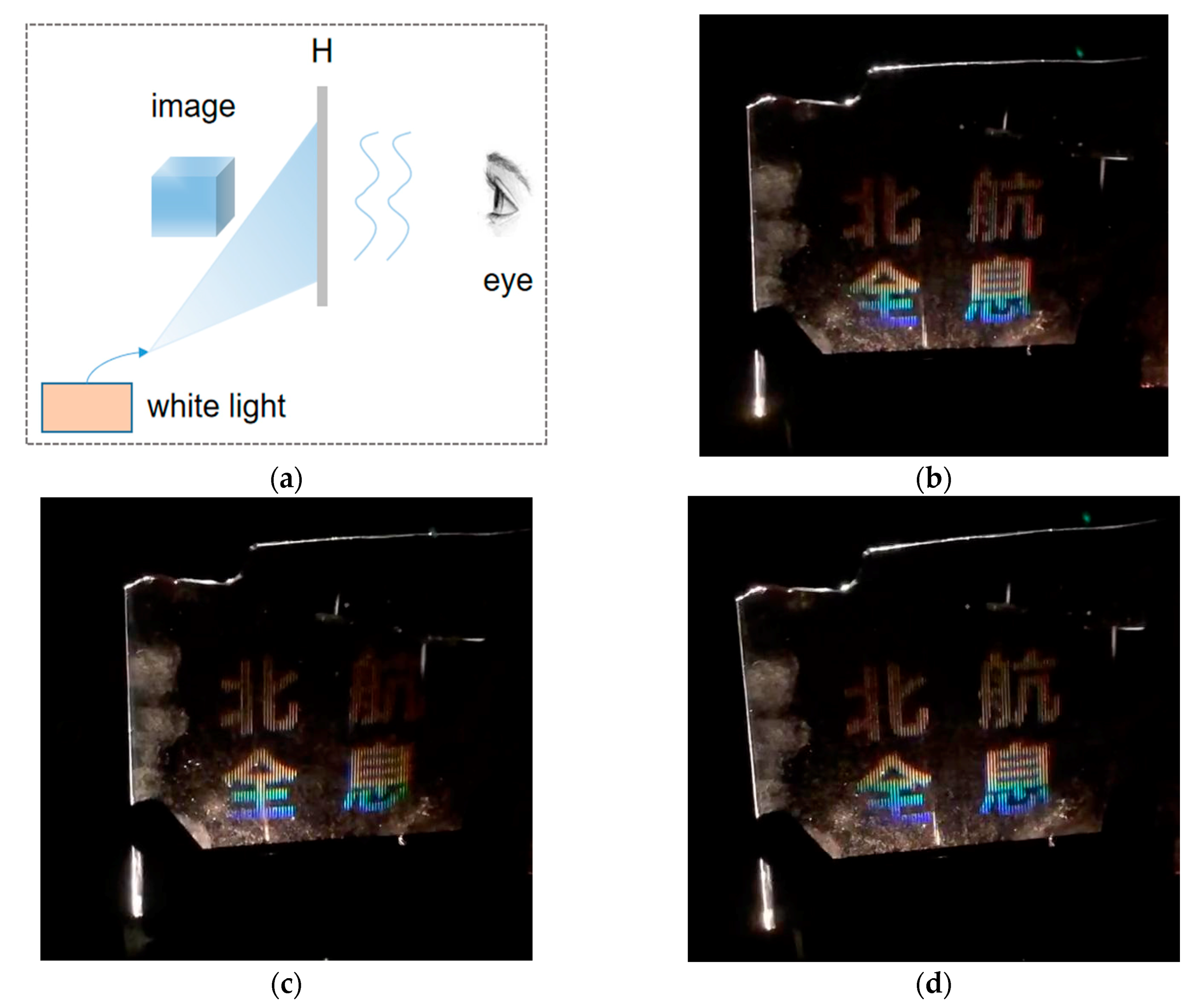
Figure 6a. The white light is coupled into the fiber and a divergent light from the fiber head illuminates the hologram H with a proper incline angle in the
y direction. The diffracted light propagates into the human eye for watching the reconstructed 3D image. The real image in front of the hologram plane or the virtual image behind the hologram plane can be watched by selecting a proper illumination angle.
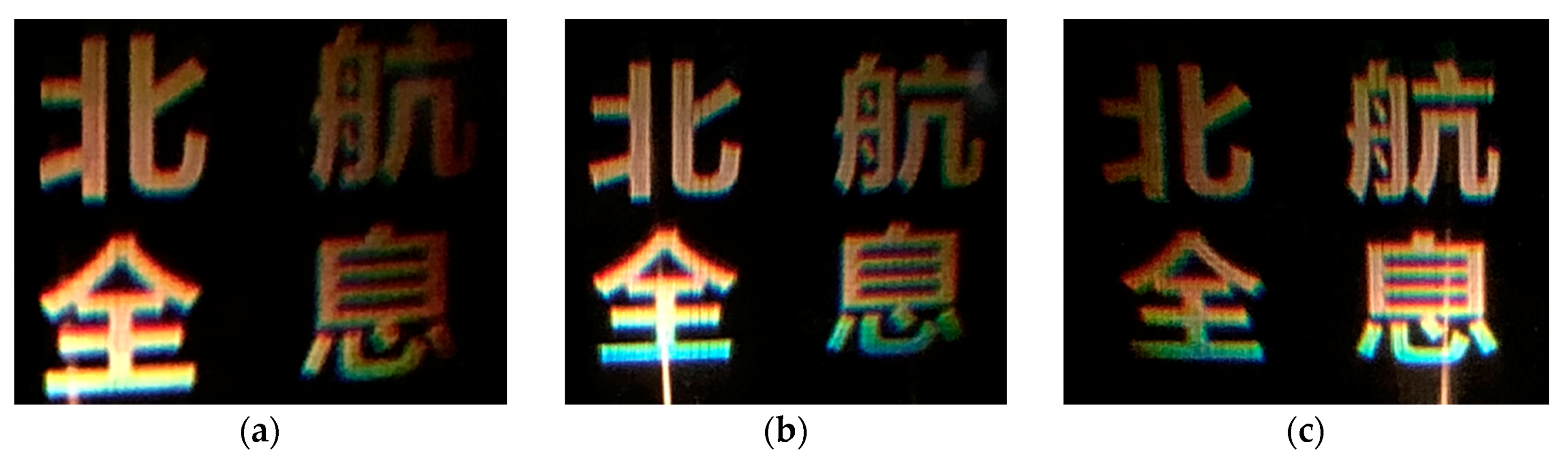
Figure 6b–d show three reconstructed images from three different viewing angles.
Video S1 shows the reconstruction from different viewpoints.
From the optical reconstruction, the parallax is smooth and the FOV is large. The brightness is a little different due to the uneven incline illumination on this large-area hologram.
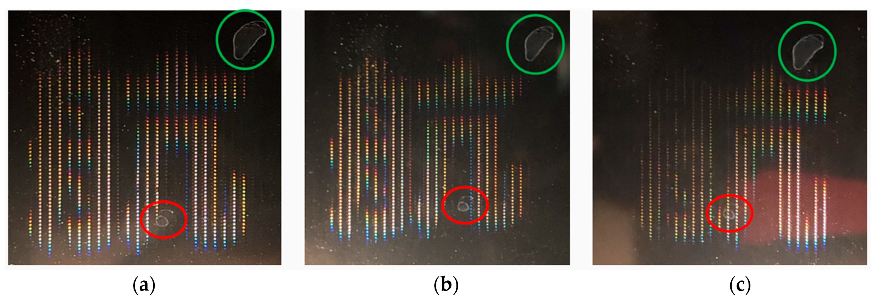
Figure 7 shows three images captured by our camera, focusing on part of the holographic plane with different viewing angles. The two speckles in the red and green circles on the holographic plane are used as reference positions. From the results we can know that different perspectives of light come from different positions on the holographic plane, which is the core point of our method to encode the propagation of each pixel in the EI to different angles with divergent sphere wave phase factors.
The large hogel size in the first experiment means that human eyes can easily distinguish each hogel on the holographic plane. The 3D image, viewed by the human eye, is comparable to watching through a fence. In order to reduce the fence effect and improve the quality of the displayed result, the second experiment is designed and carried out using the same model as the first experiment, but with different parameters. In the second experiment, the distance between the pinhole array and the holographic plane is
mm. In this situation, each hogel has a resolution of 700 × 277 pixels, corresponding to the physical size of 0.22 × 0.09 mm. The sampling pitch in each EI is set as 1 μm and the resolution of each EI is 222 × 88 pixels, which is the same as in the first experiment. The number of EIs is 287 × 725. The resolution of the full light field image is about 63.7K × 63.7K in this experiment. Other parameters are all the same as the parameters of the first experiment. The calculation time of this hologram is approximately 37 min.
Figure 8 shows the three reconstructed images.
Video S2 shows the 3D reconstruction from different viewing angles.
4. Discussion
Encoding the high-resolution light field image into a high-resolution hologram has two important advantages: displaying 3D images with higher resolutions, and dramatically decreased calculation times of high-resolution holograms. In our proposed method, a pinhole array behind the holographic plane is used for the EI’s rendering, and a divergent sphere wave is used as the phase information for each EI. However, the pinhole array can also be set in front of the holographic plane, and the convergent sphere wave can be used as phase information.
In the calculation, converting each EI to the complex amplitude information on each hogel plane using FFT is not needed in the proposed method. Additionally, the phase factor of divergent sphere waves is the same for all hogels, which means the phase factor only needs to be calculated one time and can be reused for each hogel calculation. This direct encoding method can greatly reduce the computational time of high-resolution holograms.
In the encoding process of holograms, a plane wave is used as a reference wave for simplicity. Actually, a divergent sphere wave is more practical, because the white light we used (or a white light LED) for illumination of the hologram is approximately a divergent wave. The reason why a white light can be used to reconstruct the hologram is that there is minimal distance between the reconstructed image and the holographic plane, similar to the case of the image holography, the color dispersion due to the white light illumination does not have a large influence on the reproduced 3D image. It should be noted that to display the hologram with laser as illumination is still possible with a higher resolution of reconstructed 3D images, but speckle noise will exist.
We demonstrate two experiments for 3D display with different hogel size and sampling pitch. From the results, we can conclude that the calculation time is associated with the number of object points in the 3D model and EIs, as well as the sampling interval in each EI. Well-designed parameters will guarantee high-quality reconstructed images with a relative short computational time. Parallel computing using a GPU (graphics processing unit) is still possible for further reduction of computational time.
The displayed results with white light as illumination are a grayscale 3D display. However, the concept of full color rainbow holography [
9,
12] can also be applied to our method for a full color 3D display at the cost of losing vertical parallax.
In the proposed method, the resolution of each EI and the size of the EI or hogel are related, which means a large FOV will cause large hogel sizes and lead to more of the fence effect. A large-depth 3D display is not possible with this method because an image far from the holographic plane will be blurred due to the white light illumination. However, the proposed method is still valuable for holographic packing or 3D display purposes with relatively small depth.

 ,
, 

