1. Introduction
In 1981, Sim Anderson developed a 3-fin configuration called the Thruster [
1]. At this time, surfboard design with more than two fins was revolutionary and profoundly affected the subsequent fin configuration designs of surfboards. Shortly after, the 4-fin configuration called the Quad [
1] was created. These two configurations, which now set the standard in surfing, were just found by experimental trial-and-error evaluations of multiple fin combinations [
2]. Additionally, the vast experience of the surfboard shapers has been shown to be significant for surfboard design and has been dominating the surfboard development.
Like in most other sports, the competitors—in surfing, the surfers—have evolved to a full-time professional level. The World Surf League (WSL), the former Association of Surfing Professionals (ASP), hosts high-level competitions, tournaments, and the world championships in surfing, with up to six-figure trophy money for the winner, in many countries all around the world [
3]. Surfing’s second boom in the 1980s transformed surfing into a billion-dollar industry, and eleven-time world champion Kelly Slater became one of the first surf-millionaires in the 1990s [
4].
Fluid dynamics has a significant impact on most sport types regarding equipment and athletic performance [
5]. Today, in nearly all kind of professional sports, computational fluid dynamics (CFD) is used to optimize performance and to develop new technical innovations [
6]. The advantages of CFD software tools versus a physical test setup are promptness and comparably low costs. For example, Azcueta and Rousselon [
7] demonstrated that simulations for high-performance racing boats used in America’s Cup or the Volvo Ocean Race campaigns are an excellent alternative to tank testing. This promptness of software helps to speed up the analysis of the performance of prototypes and innovative ideas. Furthermore, the high spatial and temporal resolutions combined with unconfined access to the simulation region are further advantages of CFD software tools.
In yacht sailing, Rosen et al. [
8] concentrated on the hull and underwater appendage design, and Paton [
9] focused on the fluid-structure-interaction (FSI) of yacht sails. In motorsports, Formula One is best known for the vast amount of money it spends on CFD studies [
10].
In surfing, only a few CFD studies have been carried out with a focus on the Thruster and Quad configuration within a rectangular simulation region without a surfboard geometry [
11,
12,
13]. In a previous study [
11], we investigated the fluid flow for a 3-fin configuration for different angles of attack (AoA) between 0° and 45° with steady-state and transient turbulent simulations. The main finding of that study was that the unsteady flow phenomena, which produce fluctuating forces on the fins, consequently have a significant impact on the track and roll stability of the surfboard, and occur mainly in a high AoA (between 25° and 45°). Two other studies included different surfboard types placed on a free surface [
14,
15]. The majority of these studies evaluated the feasibility of CFD in surfing and surfboard design.
In the history of the surfboard design, there have been boards without fins, with two, three, four, and five fins, and all of these configurations have different characteristics for different wave conditions. When Tom Blake introduced a stabilizing fin in 1935, he reported that he never had such control and stability [
4]. Nevertheless, the arrangement of the fins in the different configurations is very similar manufactured from different shapers. However, a systematic study of different locations is not available. Thus, in this current study, we simulate a 4-fin configuration with various fin positions to show their significant effect on the lift and drag coefficients of the entire configuration. To the best of our knowledge, no numerical parameter study on different fin positions has been done in this context. The position and alignment of the rear fins yielded 10 cases with different transverse and axial fin positions and different AoA (between 0° and 45°). The geometry of the fins is obtained from the commercial
FCS Accelerator fins. Additionally, for the commercial 4-fin configuration, we applied four different surf velocities of 5 m/s, 7.5 m/s, 10 m/s, and 18 m/s, representing different wave heights.
Our primary goal is to provide flow field data around a 4-fin configuration with both steady-state Reynolds-averaged Navier-Stokes (RANS) equations and unsteady fluid flow using unsteady RANS (URANS) simulations [
16,
17]. URANS has been shown to be essential for resolving the time-dependent fluid flow structures at high angles of attack [
11]. Both RANS models were used in combination with the SST (shear stress transport)
turbulence model [
18,
19]. Catalano and Tognaccini [
20] showed that URANS, in combination with the SST
turbulence model, provides a very good consistency to Large Eddy Simulations (LES) of wing profiles. The SST
turbulence model has proven its efficiency and correctness towards experimental data in the field of airfoils [
21,
22] and hydrofoils [
23]. Thus, RANS and URANS turbulence models, in combination with the SST
turbulence model, are widely applied and appropriate for the simulation of wing and wing-like profiles to analyze lift and drag forces [
24,
25,
26] and are also used in the field of wind turbines [
27,
28].
Our hypotheses regarding the effects of varying the positions of the rear fins and the surf-velocity on our 4-fin configuration are as follows:
In comparison to the 3-fin configuration, the 4-fin configuration is expected to be slower because more drag force is produced, and the surfer will have to apply more work to perform a turn maneuver because of the higher lift force.
Fluid flow velocity will have a significant influence on the lift and drag forces and will therefore have an immense effect on the surfer.
The various positions of the rear fins along the axial and transverse direction of the surfboard potentially have a massive impact on the lift and drag forces of the entire configuration, on the stall point, and consequently on the surfing.
Our results may also cross-fertilize fields of application that use lifting bodies that are similar to surfboard fins, e.g., sailboat keel fins [
29] and kitefoils [
30].
2. Materials and Methods
2.1. Surfing Hydrodynamics
For a wave height
of 1.5 m and a corresponding wave velocity
of 4 m/s, a typical surfer’s velocity
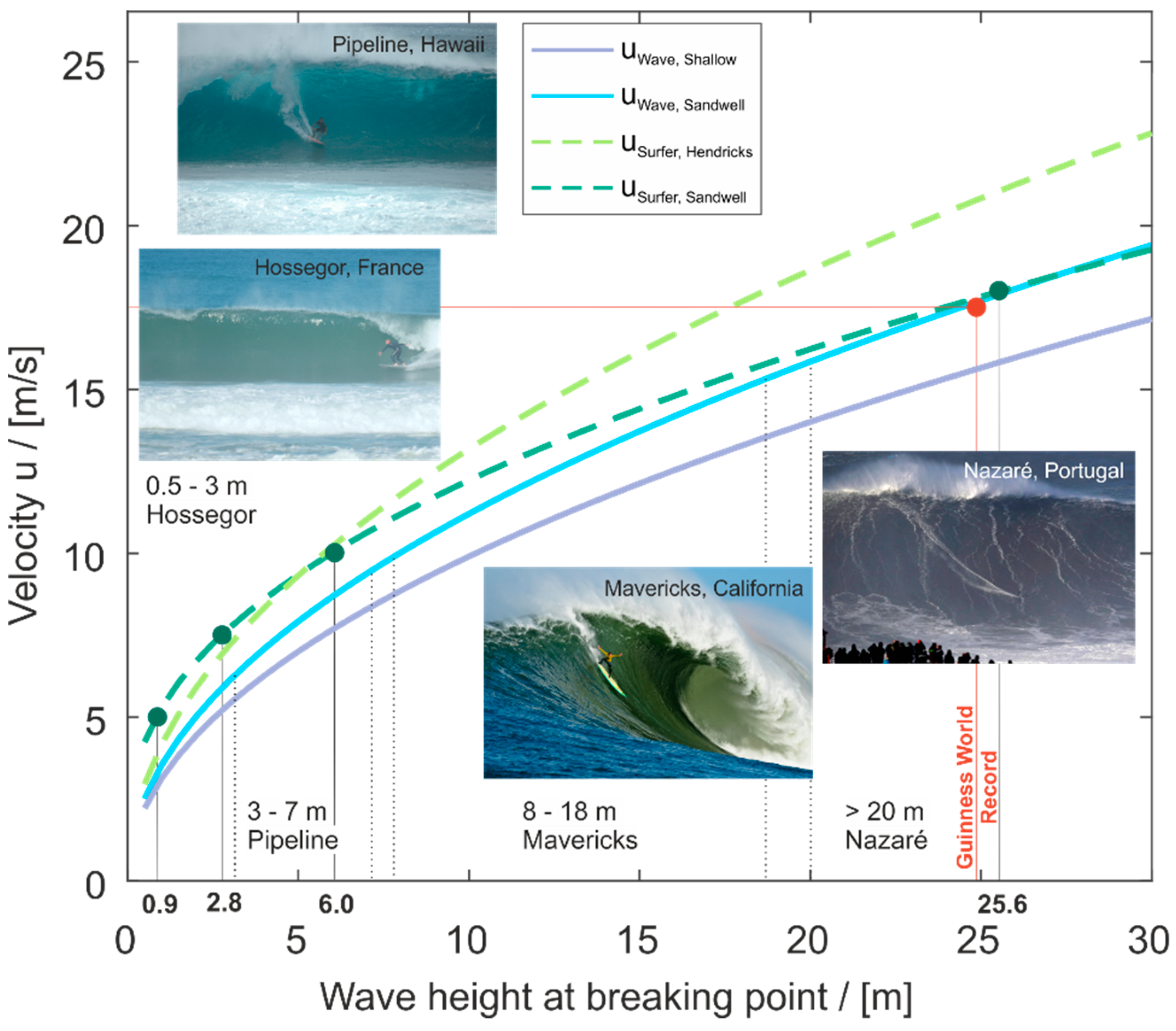
is approximately 6 m/s [
31], as shown in
Figure 1. Increasing the wave height increases the wave velocity and, consequently, the surfing velocity—up to a certain limit [
32].
The following basic equations describe the velocity
of a shallow wave Equation (1) [
33] and the velocity of a shallow wave with the wave height multiplied with an empirical factor of 1.28, see Equation (2) [
34]. The velocity of the surfer is described with two different equations Equation (3) [
35] and (4) [
34]. Whereas the velocity in Equation (3) is only determined by the speed and height of the wave without considering the prevailing drag of the surfer-surfboard system, Equation (4) is based on the kinetic and potential energy of a surfer and the wave. All velocities are absolute values.
is the gravitational acceleration,
is the wave height at the breaking point,
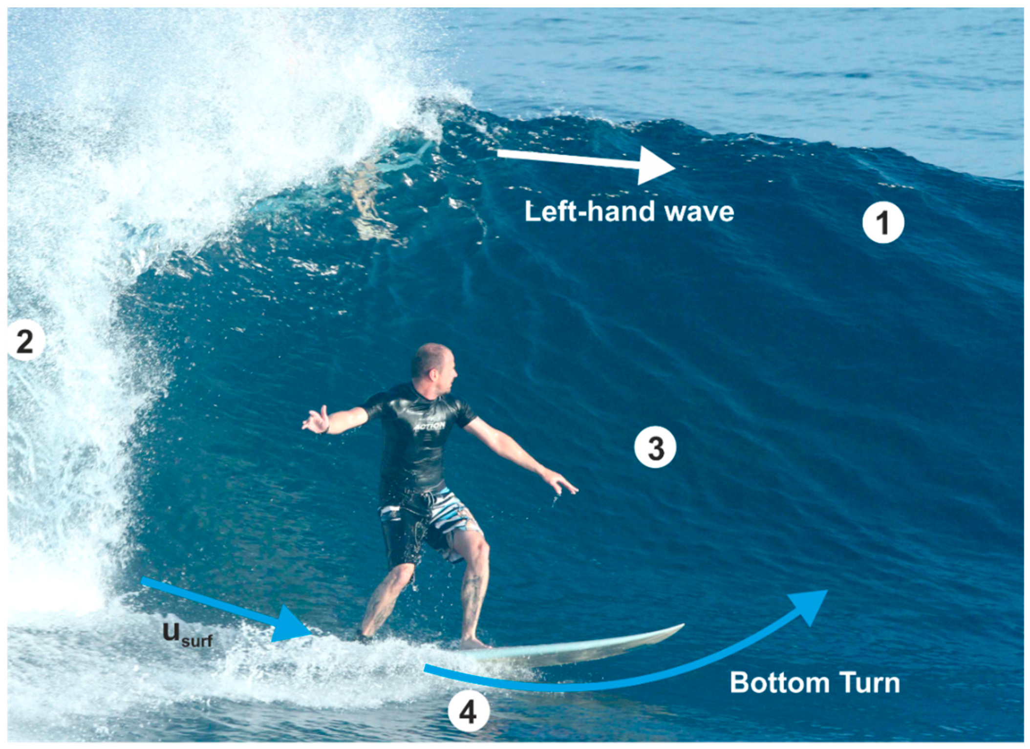
is the gradient of the steepest surfable part of the wave’s pocket; see
Figure 2, (1.0 for 45° of the slope of the wave),
is the time in the wave’s pocket (we chose
),
is the drag coefficient in the air of the surfer (1.0 for a standing human),
is the reference area of the surfer (1.5
for a standing human),
is the surfer’s velocity, and
is the fluid density.
Nevertheless, an increasing board speed is also increasing the overall drag of the surfboard that is limiting the surfing velocity. The Guinness World Records confirmed in 2017 that Rodrigo Koxa surfed a 24.38 m (80 ft.) wave [
36]. Putting this wave height into the basic kinetic and potential energy equation (see Equation (4)), the velocity of the wave results in 17.5 m/s, leading to the assumption that, currently,
has a maximum of around 18 m/s [
37].
When the wave peels to the right from a viewing perspective of the surfer looking to the shore, the wave is called a right-hand wave, and when the wave peels to the left the wave is called a left-hand wave [
38]; see
Figure 2.
After dropping into the wave, the surfer gets up and surfs down the pocket of the wave with the surfing velocity
; see
Figure 2. To stay in the wave’s pocket (energy zone), the surfer performs a bottom turn, which is a common maneuver that brings him/her back to the pocket of the wave. In everyday surfing, the surfer surfs up and down the wave in alternating order traveling with the wave.
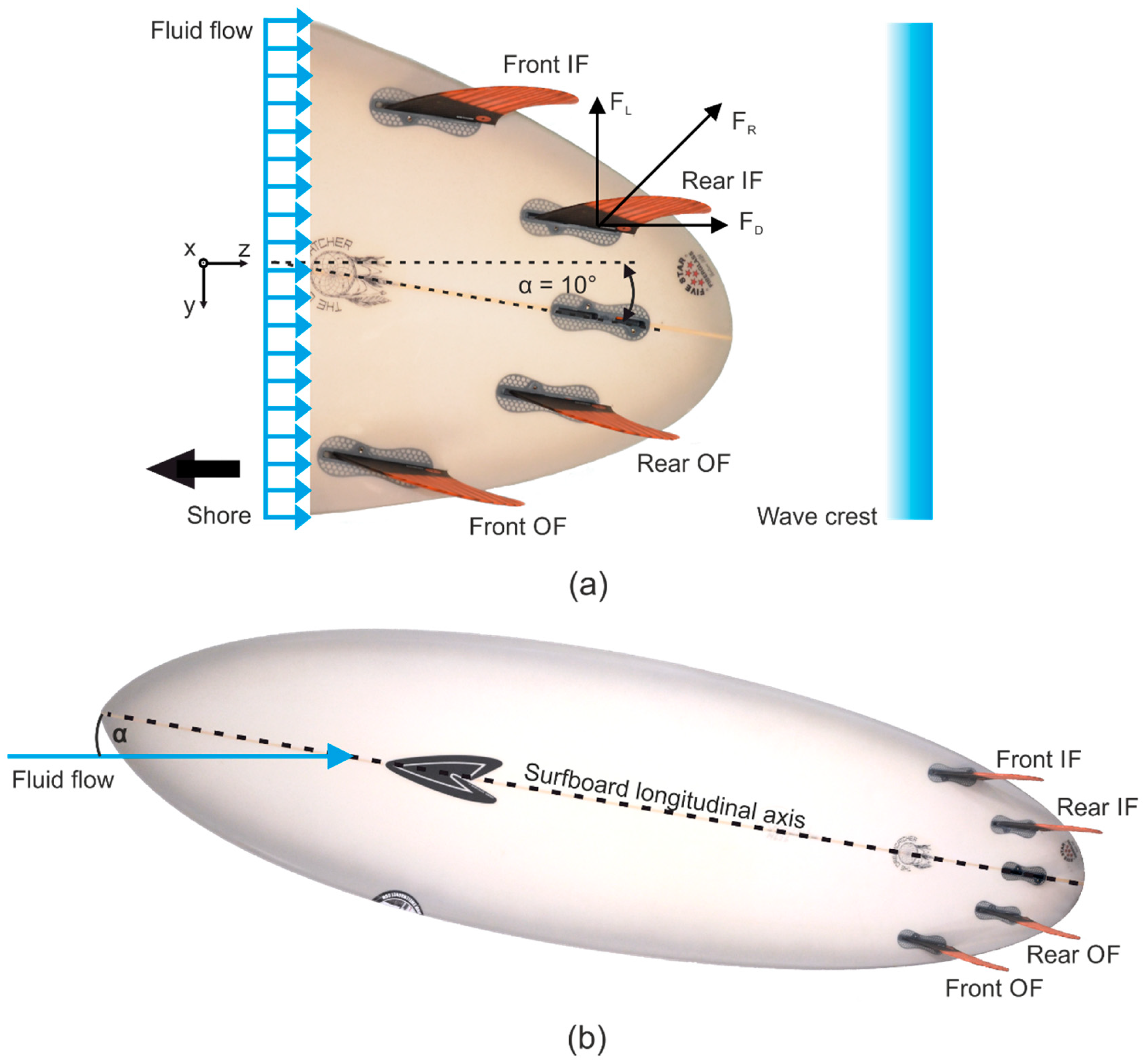
The declaration of the fins within the investigated 4-fin configuration and for the basic surf maneuver of a bottom turn analyzed in this study are as follows, see also
Figure 3a,b:
Front fins: the front fins in prevailing surfing direction.
Rear fins: the fins next to the tail of the surfboard.
Outside fins (OF): the fins next to the shore.
Inside fins (IF): the fins next to the wave crest.
A more surf-common classification of the outside and inside fins is to define them as working and passive fins. The reason is that, regardless of whether a rider is turning into or away from the wave, the engaged fins are on the inside of the surfing arc. For any typical fin configuration, in turns, the working fins are fully immersed in the water, whereas the passive fins may also be partly outside of the water. In our study, the outside fins are the passive fins, the inside fins are the working fins, and both fins are fully immerged with the fluid flow.
Similar to airfoils, a surfboard fin represents a streamlined body in a fluid flow that generates lift and drag forces on it.
Figure 3a shows the lift and drag forces acting on the rear IF at an AoA (
) of 10°. The drag force
appears in the direction of and the lift force
perpendicular to the main flow direction [
16]. A positive lift force represents a turn of the surfboard-fin-system to the shore, and a negative lift force presents a turn into the wave’s pocket. A positive drag force is aligned with the flow direction. The turning axis, which the forces induce moments to, is perpendicular to the surfboard surface and highly depends on the position of the center of gravity of the surfer-surfboard-system.
The AoA defines the angle between the main flow direction and the longitudinal axis of the surfboard. If the fluid flow is parallel to the longitudinal axis, the resulting AoA is 0°. In general, the AoA ranges between −45° and 45° [
39]. In our simulation cases, positive AoAs are related to a typical bottom turn to get back into the wave.
2.2. Geometric Dimensions of the Fins
The
FCS Accelerator II fins (
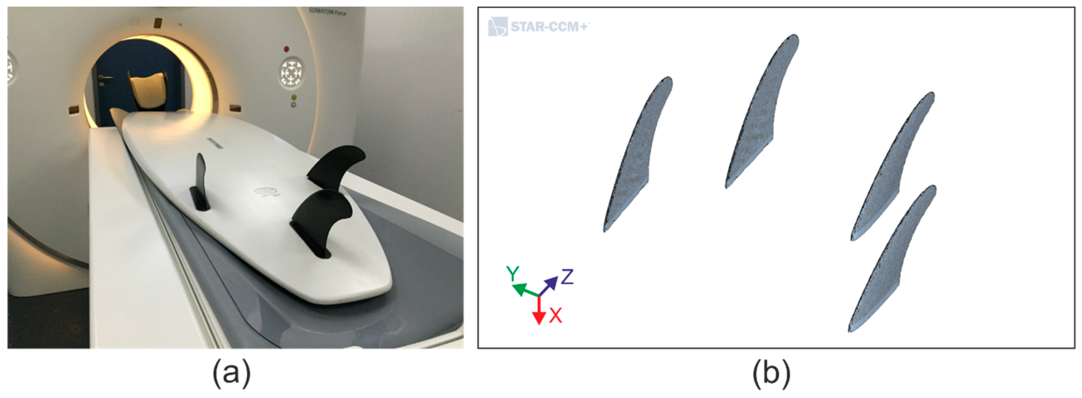
FCS, Newport Beach, NSW/Australia) plugged on a surfboard were scanned in a computer tomograph (CT) of type SOMATOM Definition AS 64 (SIEMENS Healthineers, Forchheim, BY/GER); see
Figure 4. The high-resolution CT images were post-processed with a Gaussian filter and a Marching Cubes algorithm, which generates watertight and manifold triangle meshes [
40]. For obtaining just the results of the fins without the influence of a surfboard geometry, only the 3D geometries of the fins, arranged in a commercial 4-fin configuration of a
ROBERTS Surfboards (Ventura, CA, USA)
The Dreamcatcher 6′8 model, were imported into STAR-CCM+; see
Figure 4b.
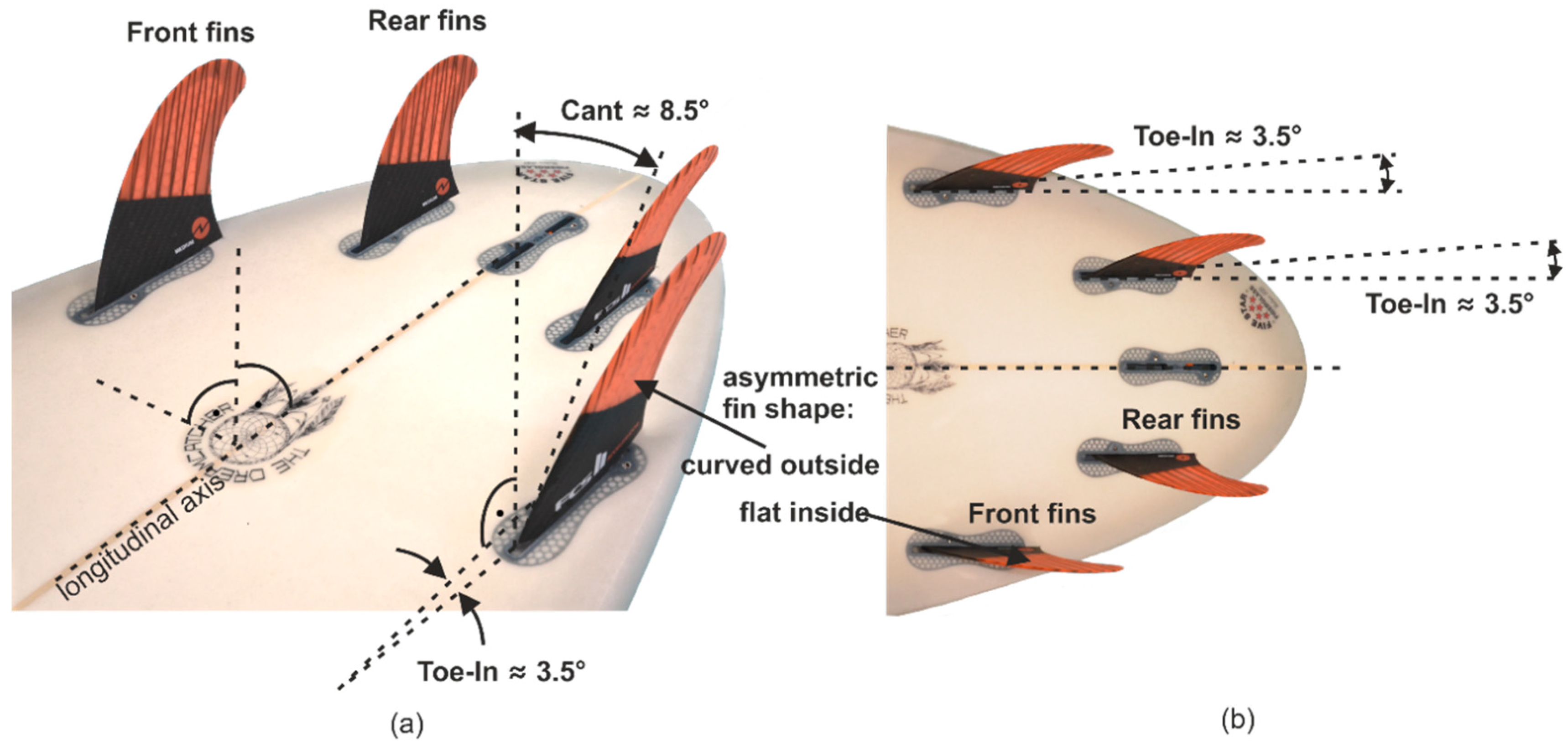
The cant angle of the fins within the 4-fin configuration is approximately 8.5°; see
Figure 5a. The Toe-In angle is approx. 3.5°; see
Figure 5a. The
FCS Accelerator II fins have an asymmetric shape with a flat inside surface and a curved outside surface; see
Figure 5a,b.
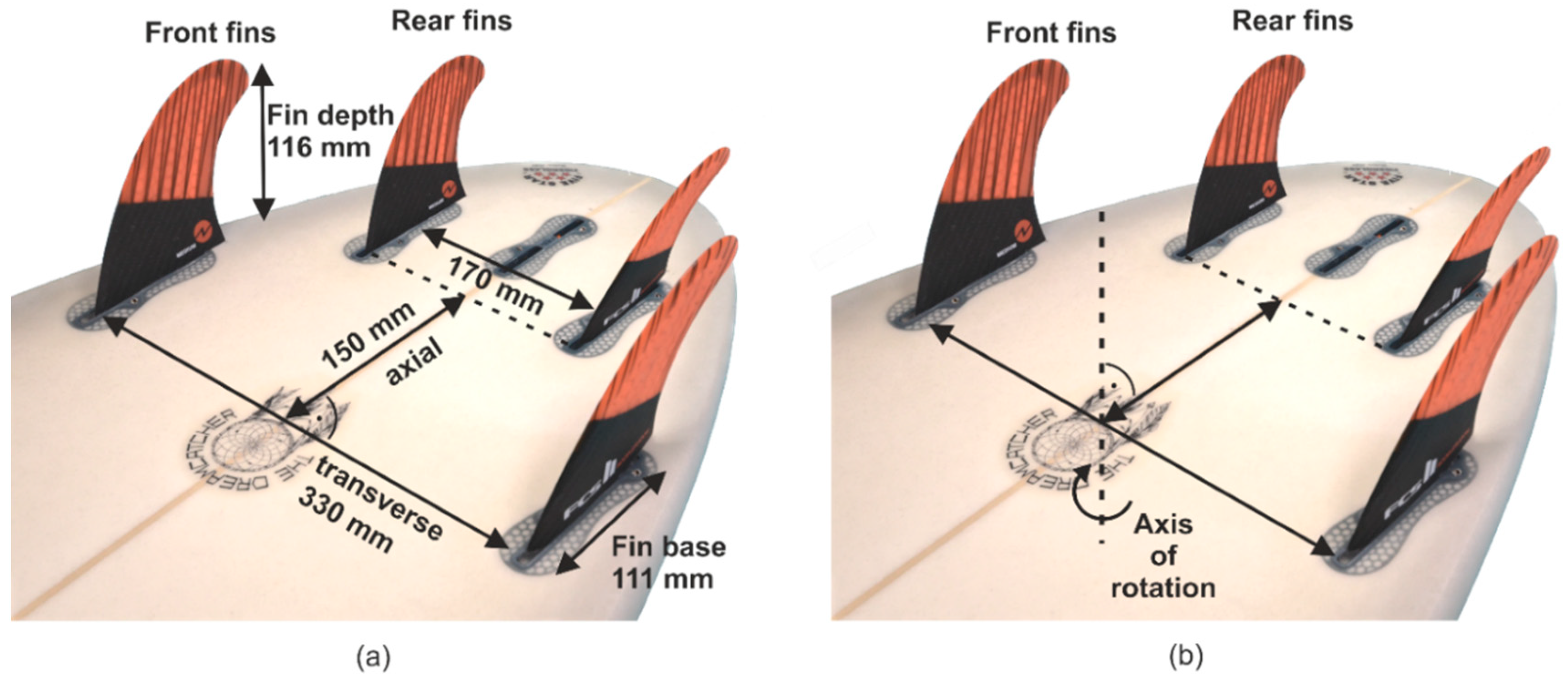
The depth of the fins is 116 mm, and the base length is 111 mm; see
Figure 6a. Furthermore, the fin’s planform area is 9860 mm
2. The initial distances in the transverse direction between the front fins are 330 mm and for the rear fins 170 mm; see
Figure 6a. The axial distance of the rear fins to the front fins is 150 mm. The entire fin configuration is rotated around an axis to realize the AoA between the fins and the fluid flow, which is located precisely at the center point between the leading edges of the front fins; see
Figure 6b.
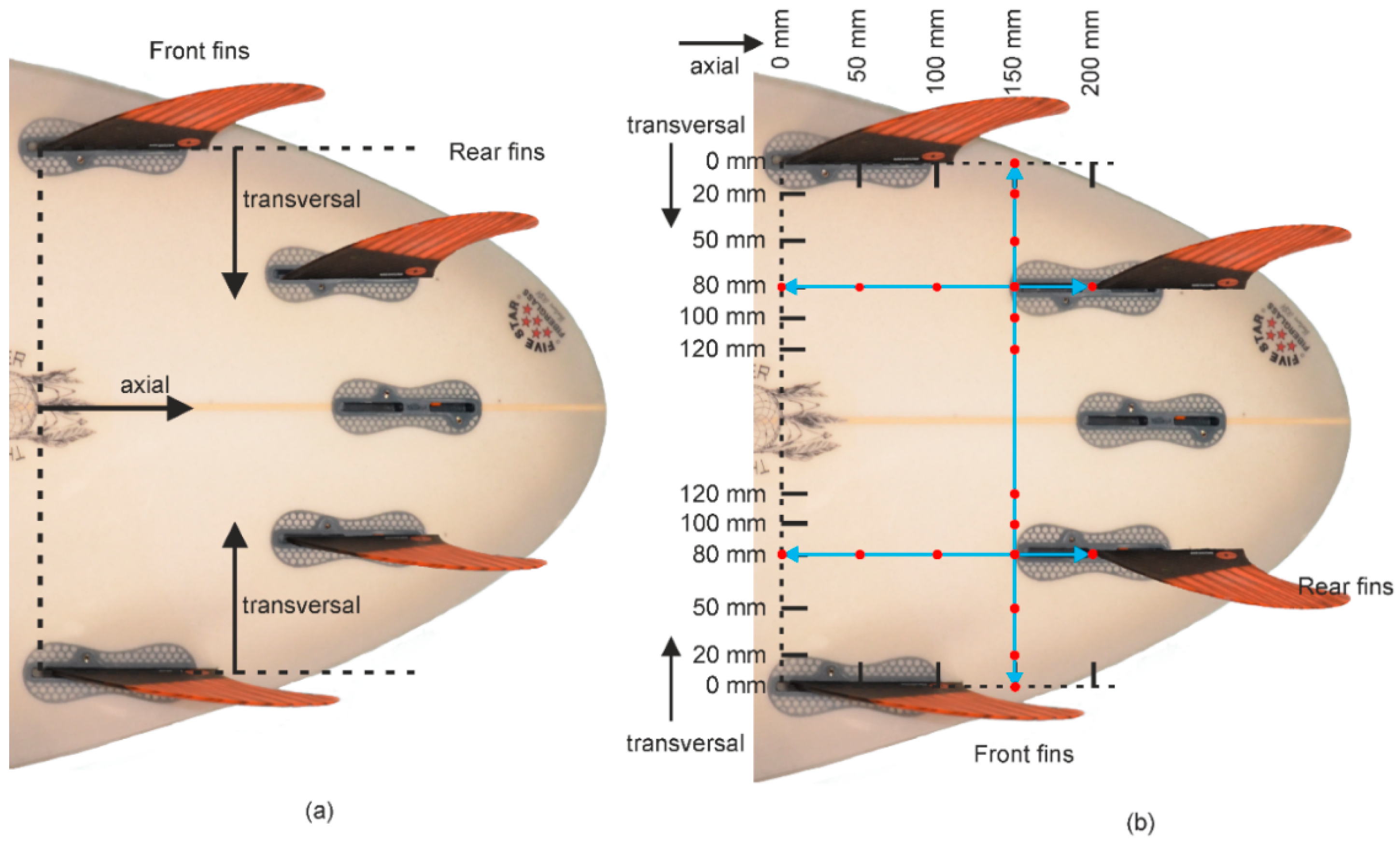
Besides the original configuration, ten fin configurations were created by varying the positions of the rear fins within the 4-fin configuration, as displayed in
Figure 7a. Therefore, the rear fins were stepwise moved in the axial and transversal direction according to the following constraints:
Both front fins are fixed.
Just symmetric fin configurations are realized.
The displacement of the rear fins is oriented on the positions of the intersection point board and leading edge.
According to these constraints, the ten different configurations are indicated with the red dots in
Figure 7b. The commercial CT scanned position of the rear fins corresponds to the configuration 80 mm in the transversal and 150 mm in the axial displacement; see
Figure 7a. For a clear definition of the configurations, the following notation is introduced: e.g., T:80 A:150 for the commercial configuration.
2.3. Simulation Region and Boundary Conditions
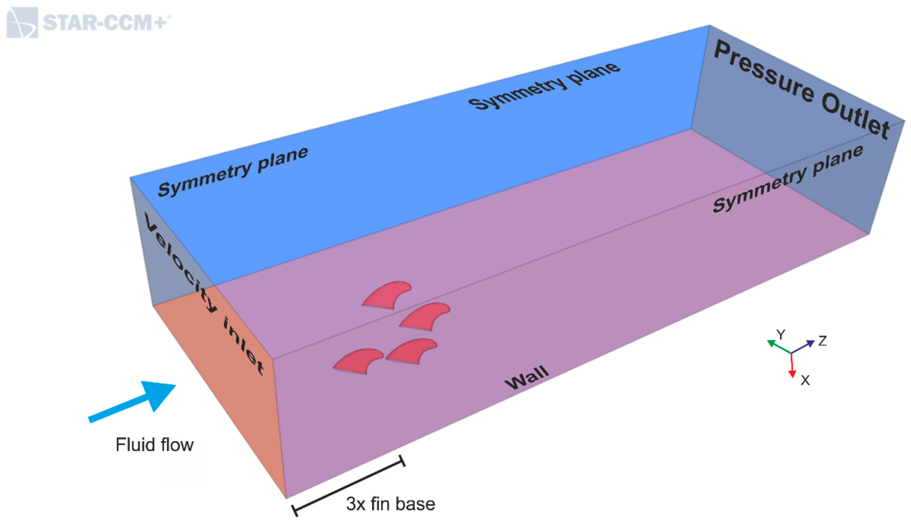
The fins are placed at the bottom wall of a rectangular box that is representing the numerical fluid domain. This rectangular simulation region has similar dimensions as in [
13,
41]; see
Figure 8. The front fins are set at a distance of three times the base length of the fins from the inlet boundary; see
Figure 8.
The fin’s surface and the bottom wall of the simulation region are defined as an impermeable wall with a no-slip condition. At the inlet boundary, the fluid velocity was set to 5 m/s, 7.5 m/s, 10 m/s, or 18 m/s. At the outlet boundary, at three times the base length of the fins downstream of the front fins, the pressure was set to be constant at 0 Pa. Hence, no reversed flow of the fluid flow occurs at the outlet boundary. The two sidewalls and the top wall are defined as symmetry planes.
Regarding
Figure 6b, the 4-fins are rotated clockwise for generating inflows in the range of 0° < AoA < 45° in 5° steps, which correspond to a left-hand surfing maneuver.
The density is set constant (, resulting in an incompressible fluid flow. The values for the parameters of the simulation settings are: inlet velocity , mach number , density , kinematic viscosity .
2.4. Mesh Generation and Independence Study
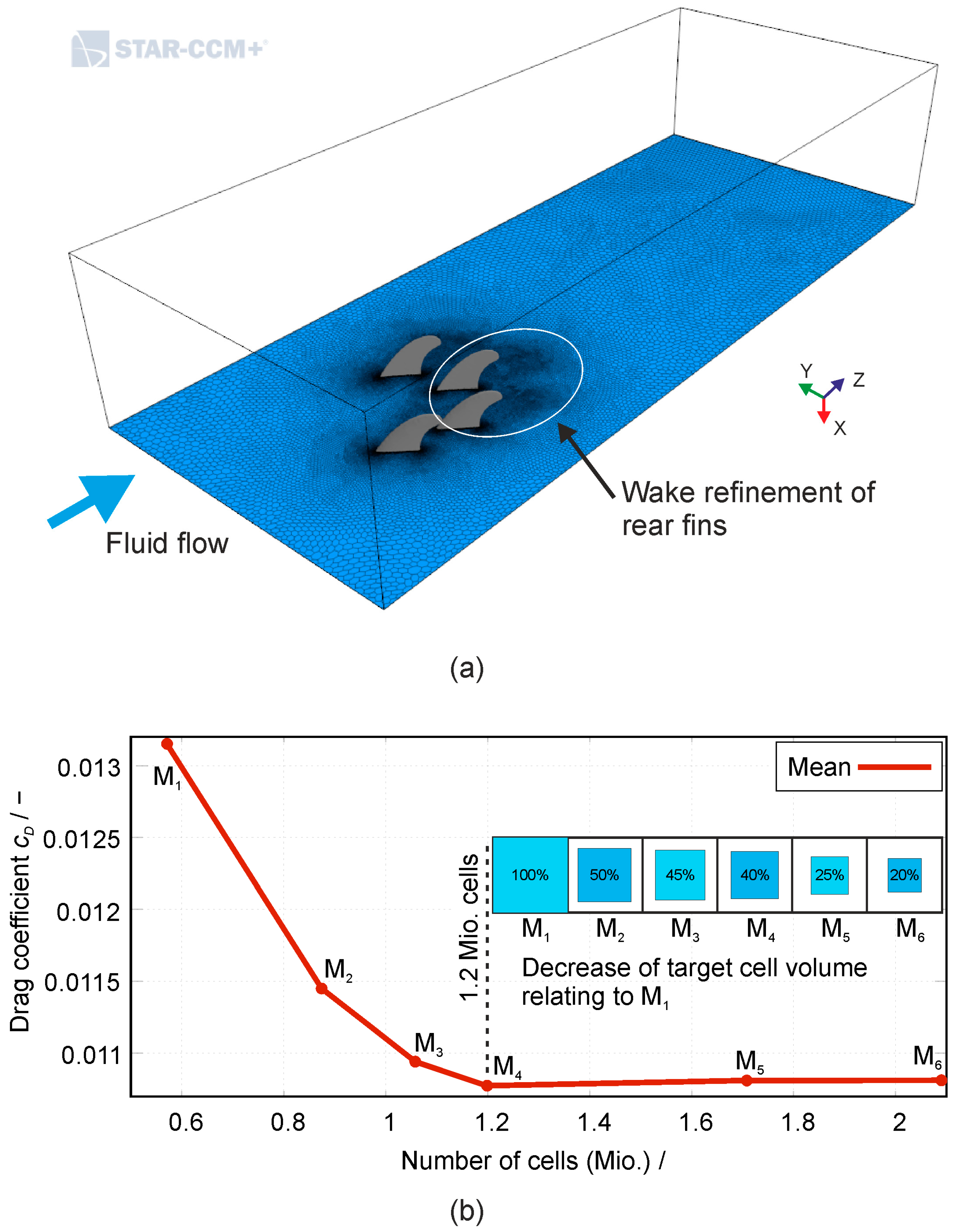
For resolving the boundary layers at the fins, ten prism layers were added on the fin surfaces. Prism layers are hexahedral cell layers that are aligned with the surface contour of the fin. The overall thickness of the prism layers depends on the inlet velocities and amounts to between 2 and 8 mm, which corresponds to an inlet velocity between 5 and 18 m/s, yielding a y
+ between 30 and 60. Furthermore, a wake refinement of the grid downstream of the fins was performed in STAR-CCM+ to accurately resolve the increasing recirculation with increasing AoA; see
Figure 9a.
Based on these settings, and using unstructured polyhedral cells, a grid independence study was carried out. It includes six different meshes (M
i) with an increasing density to identify the required grid resolution.
Figure 9b shows the drag coefficient as a function of the number of cells. The deviation of the drag coefficient for meshes M
5 and M
6 ranges between 0.3% and 0.4% compared to M
4. We chose that M
4 with approximately 1.2 million cells is the proper grid configuration to perform the 4-fin parameter study.
2.5. Numerical Methods
The strategy of the numerical modeling applied here is similar to [
2,
13] and [
14]. According to our previous study [
11], the flow was computed based on the incompressible Navier-Stokes equations with the cell-center Finite-Volume-Method (FVM) [
16] within the CFD software STAR-CCM+ (Siemens PLM Software, Plano, TX, USA).
The turbulence flow was simulated based on the Reynolds-Averaged Navier-Stokes (RANS) and Unsteady Reynolds-Averaged Navier-Stokes (URANS) equations in combination with the SST (shear stress transport)
two-equation eddy-viscosity model [
17,
18,
19]. The model combines the good performance of the
model in free separated flow regions and the
model that showed high accuracy in turbulent boundary layers [
42]. As shown in [
11], RANS simulation results are appropriate for AoAs that range between 0° and 15°, and for AoAs ≥ 20° URANS simulations are necessary to resolve the unsteady flow separation from the fins and the resulting force fluctuation.
For a sufficient modulation of the near-wall flow, STAR-CCM+ provides an additional high-y+ model that can handle coarse meshes with a y
+ > 30 [
43]. The high-y+ model is based on the standard logarithmic law of the wall model. Depending on the AoA, the y
+ values for the first grid layer at the surfaces of the fins were specified to be in the range of 30 to 90. The target value for y
+ is 60. Therein, the first cell centers next to the wall are located in the log-layer of the turbulent boundary, which describes y
+ as logarithmic function of u
+ within the standard log-law [
44]. For the transient URANS simulations, the time step size was adapted for each AoA to satisfy a Courant–Friedrichs–Lewy (CFL) condition
at the fins surfaces where the mesh is finest [
45]. As a time discretization scheme, a 2nd order implicit unsteady method was applied, which works for CFL > 1 [
46].
Figure 3a shows the lift and drag forces acting on the rear IF at an AoA (
) of 10°. In this study, the absolute lift and drag forces (F
L and F
D) itself, and the forces as non-dimensional lift and drag coefficients, as defined by [
16], were determined:
is the reference area (the planform area of the fins), and is the fluid density.
The absolute values of the lift and drag forces are calculated by summing up the pressure and shear forces for each element (index k) at the surfaces of the fins [
43]:
Hereby,
is the absolute lift force,
is the absolute drag force of the fin,
is the associated vector in flow direction, and
is the associated vector perpendicular to the flow direction; see
Figure 3a. Furthermore, k is the index number of the elements, N is the number of the elements at the surface,
and
are the vectors of the pressure and shear forces at each element,
and
are the hydrodynamic and the reference pressure,
is the shear stress tensor, and
the face area vector.
The lift and drag coefficients are separately calculated for each fin, and the mean coefficients for the entire fin configuration are calculated by the sum of the four fin forces divided by the sum of the four fin areas [
13].
Additionally, the lift-to-drag ratio (L/D) is analyzed corresponding to aircraft aerodynamics [
47]. However, the airfoil efficiency parameter L/D is a measure of the fuel consumption to lift the aircraft. This interpretation is not applicable in surfing. In surfing at a specific AoA, a maximum L/D indicates the surfboard speed-up is maximum due to low drag, whereas the lift force guarantees good stability during the speed up.
Unfortunately, there are no experimental data of the 4-fin configuration available. However, a validation of the 3-fin configuration against experimental data was shown in [
11].
The simulations of the 4-fin configurations were performed at the Emmy and Lima cluster at the Erlangen Regional Computing Center (RRZE).
4. Discussion
4.1. Lift and Drag of the Investigated Commercial 4-Fin (T:80/A:150) Configuration
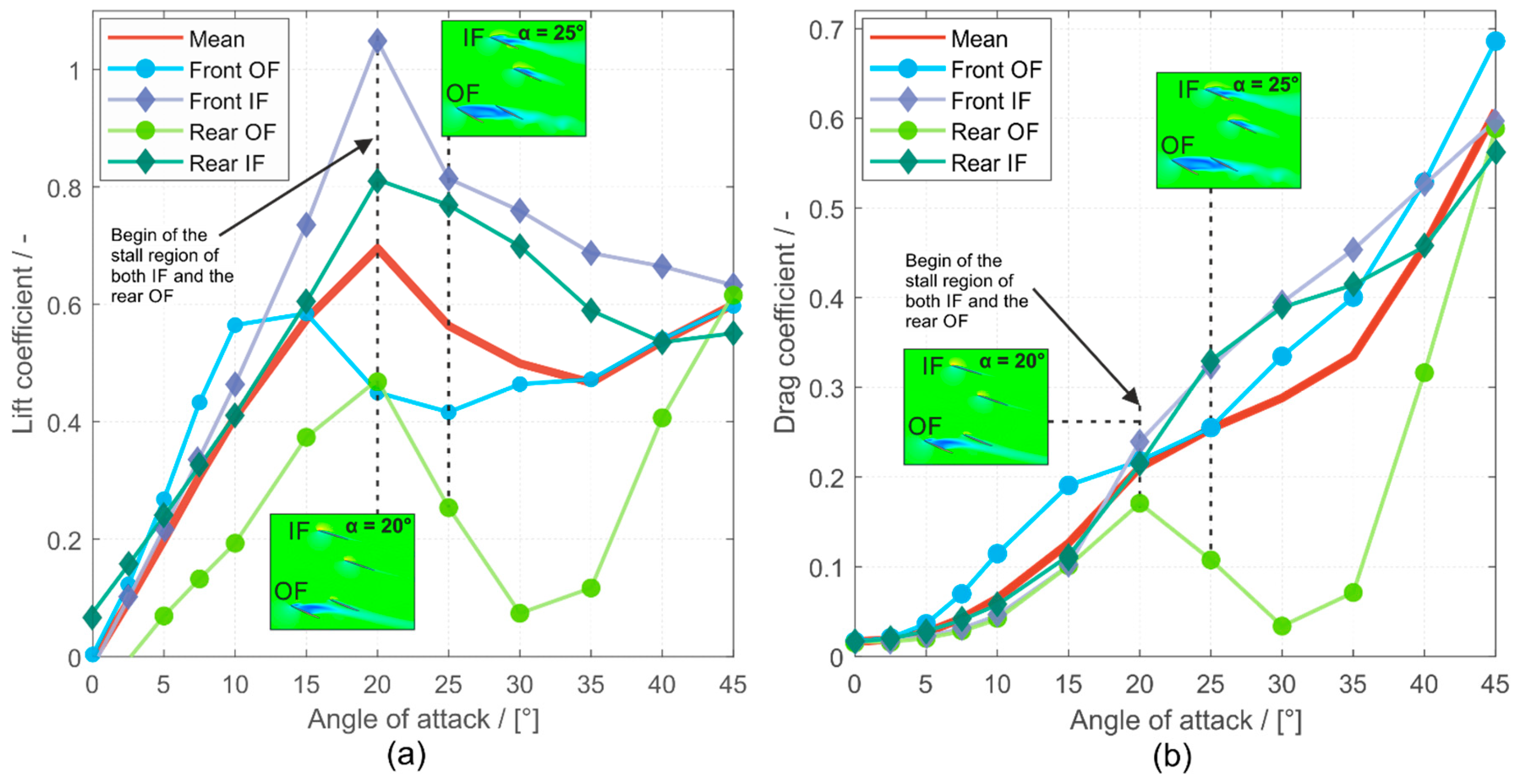
In principle, the lift forces cause a torque around the center of mass of the surfboard that forces the board to align with the main direction of the wave propagation directed to the shore. Considering the interaction between the surfer and the board, the lift constitutes the force that the surfer has to overcome to deviate the board from its actual direction to perform a turn maneuver. Thus, for high stability during the maneuver, the absolute value of the lift force and its gradient with regard to the AoA are the most relevant parameters. Comparing the lift coefficient and lift force between the 4-fin and the 3-fin configuration reported in [
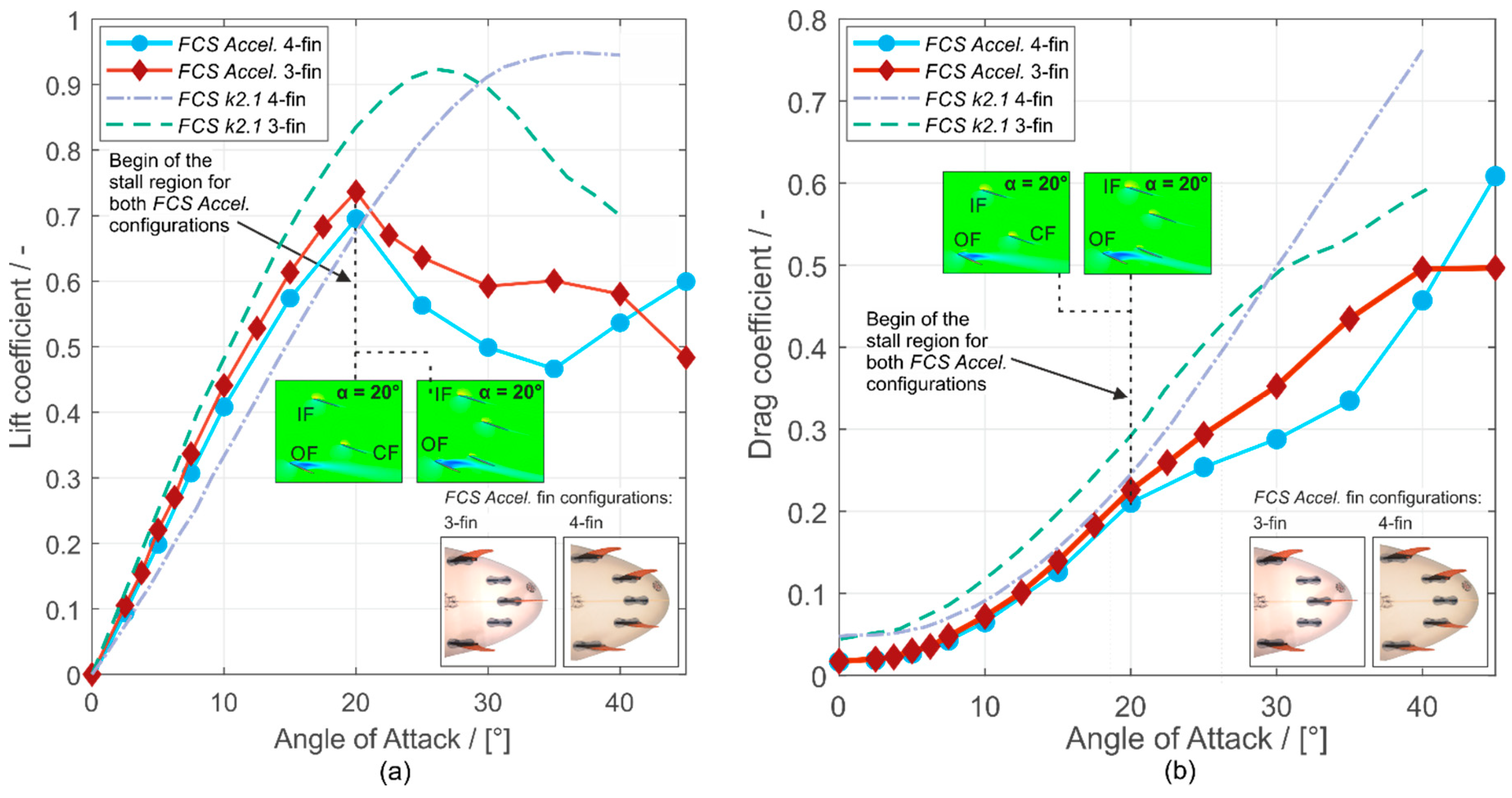
11], the 4-fin configuration produces a lower lift coefficient in the AoA range up to the stall point. However, the overall absolute lift forces produced by the 4-fin configuration are higher than those of the 3-fin configuration; see
Figure 17a.
Furthermore, the increase in force with rising AoA is also much more significant, meaning that the surfer gets a much larger and clearer lift feedback. Both effects indicate a better stability and controllability of the board by the surfer. However, the surfer has to apply much more work to perform a turning maneuver, which may impede the performance of fast maneuvers, as described in [
1].
Analogically to the lift coefficient and the lift force, the drag coefficient of the 4-fin configuration is lower, but the overall drag force is higher than that of the 3-fin configuration; see
Figure 17b. Moreover, reaching higher AoAs after stall, the drag force and the force fluctuations become dominant, as reported for the 3-fin configuration [
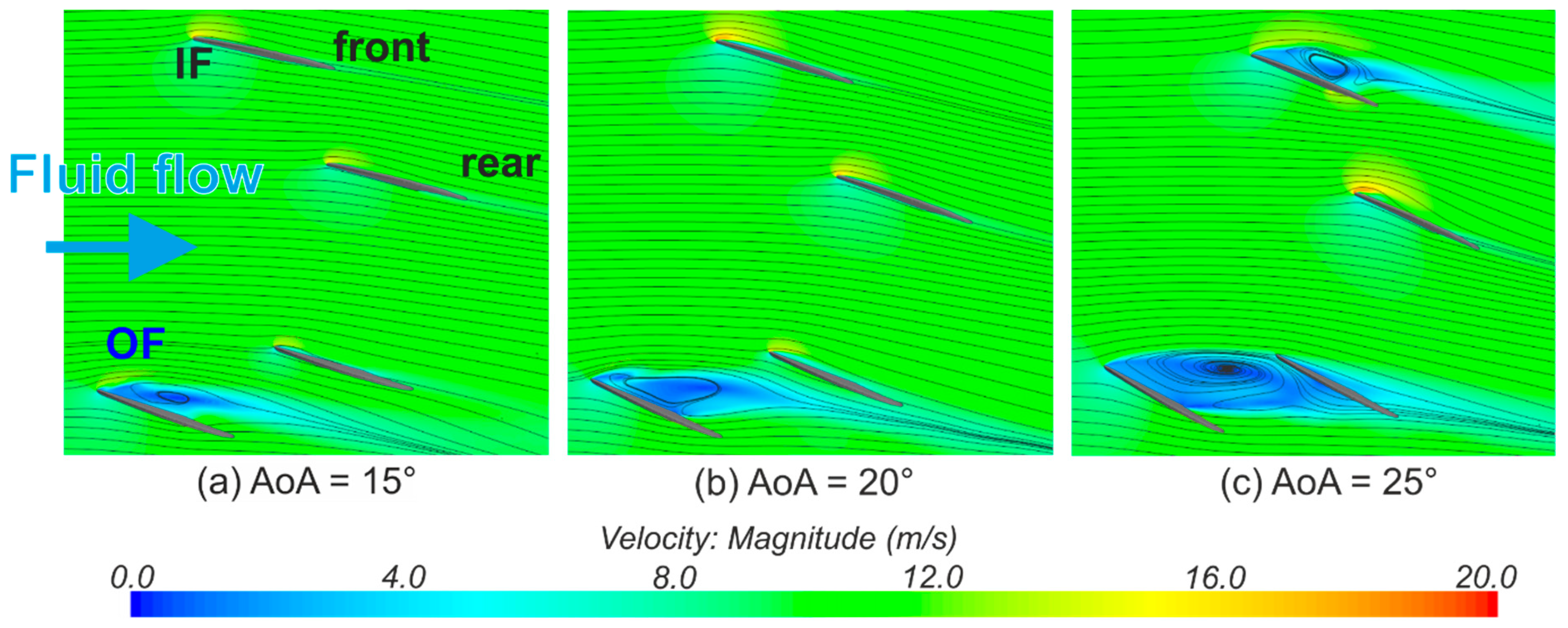
11]. These fluctuations of the lift and drag forces originate from the vortex shedding, which potentially leads to the reduction of stability; see
Supplementary Materials Videos SV1–SV6. We suppose that in the 4-fin configuration, the drag force and the force fluctuations are more significant than the ones in the 3-fin configuration, showing the worse controllability and stability of the 4-fin configuration in high AoAs. This again indicates the better applicability of 3-fin configurations for the performance of fast and advanced maneuvers. These findings support our Hypothesis 1.
The trends of the lift coefficients of the OF profoundly influence the lift coefficient of the entire configuration. The drag coefficient of the rear OF significantly decreases after the stall point and therefore positively affects the drag coefficient of the entire configuration, causing it to stay low and the velocity to stay high during a turn. The higher the AoA during a turn maneuver, the more velocity a surfer loses. The trends of the lift and drag coefficients of the four single fins and the entire configuration follow those of [
11,
12,
13] and show the trend of the basic airfoil theory [
16,
47].
4.2. Comparison of 3- and 4-Fin Configurations Using FCS Accelerator Fins from This Study and Falk et al. 2019, and FCS k2.1 Fins from Gudimetla et al. 2009
This section of the discussion compares the lift and drag coefficients and the lift-to-drag ratio of the entire 3- and 4-fin configurations using (1) the
FCS Accelerator fins from this study and Falk et al. [
11], and (2) the
FCS k2.1 fins that were used in Gudimetla et al. [
13]. The 3- and 4-fin configurations from [
11] and this study are the commercial 3- and 4-fin positions of
THE DREAMCATCHER surfboard. The dimensions and positions within the 3- and 4-fin configurations using the
FCS k2.1 fin from [
13] are similar to that of
THE DREAMCATCHER but not precisely known. Comparing and discussing both 3-fin configurations was already done by [
11].
Figure 17a presents the lift coefficients of the 3- and 4-fin configurations with the
FCS Accelerator and the
FCS k2.1 fins.
Figure 17b compares the drag coefficients of the 3-fin and 4-fin configurations.
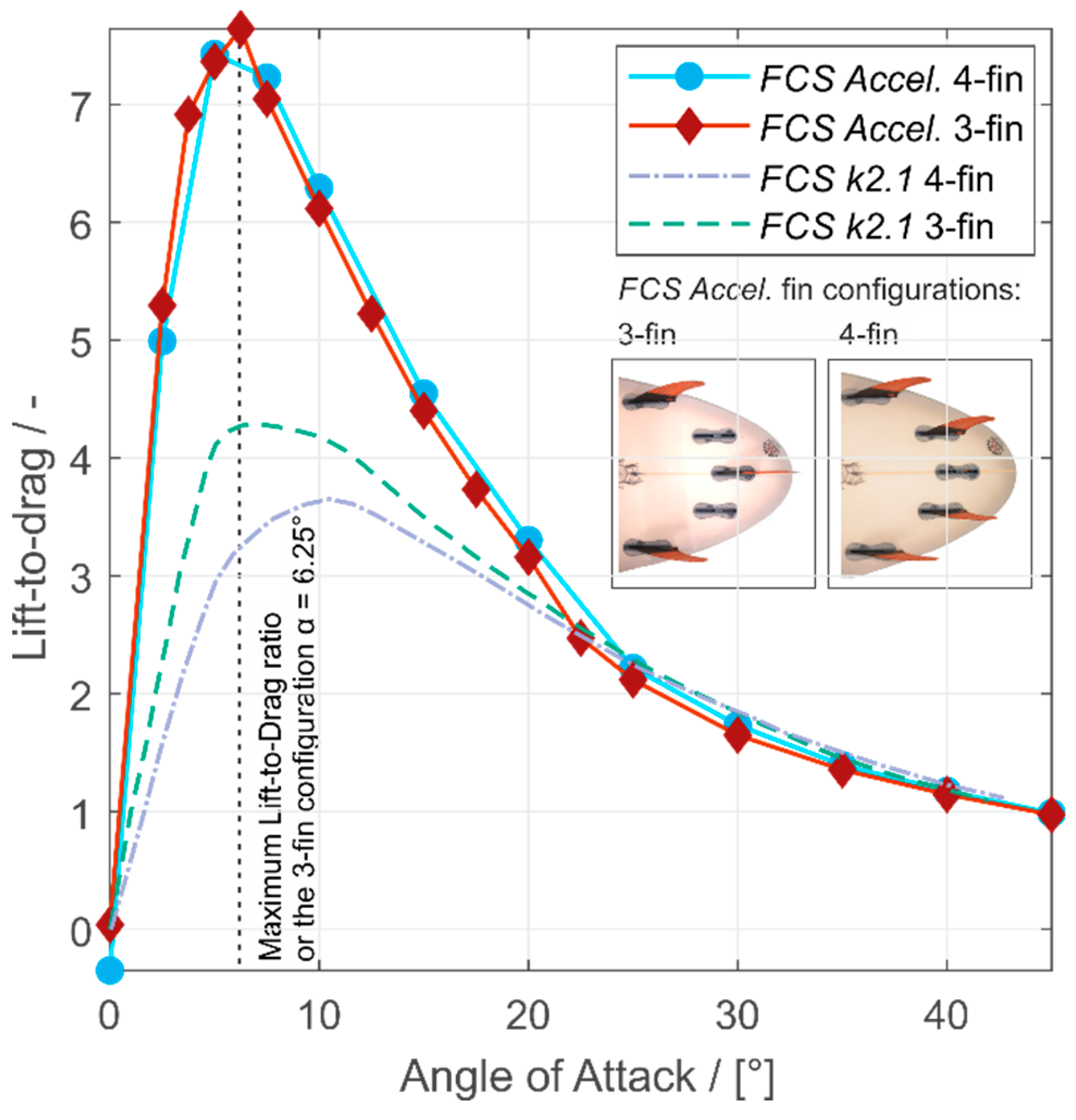
Figure 18 shows the lift-to-drag ratios of the 3- and 4-fin configurations using the
FCS Accelerator and
FCS k2.1 fins. All three figures show the same behaviors for all four configurations, much like they are previously described in
Figure 10 and
Figure 16.
4.2.1. Comparing Both 4-Fin Configurations
Lift: The maximum lift coefficient of the FCS Accelerator 4-fin configuration is 0.69 and differs by 27.3% compared to the FCS k2.1 fins. The stall point of the FCS k2.1 4-fin configuration is located at an AoA of 35° and that of the FCS Accelerator at an AoA of 20°.
Drag: The drag coefficient of the 4-fin configuration with FCS Accelerator fins increases over the whole range of AoA to a maximum of 0.61 at an AoA of 45° and that of the FCS k2.1 fins to a maximum of 0.74 at an AoA of 40°. The minimum difference of the drag coefficients of the 4-fin configuration with FCS Accelerator fins and of the FCS k2.1 fins is 0.03 at an AoA of 5°.
Lift-to-drag: The lift-to-drag of the 4-fin configuration using the FCS Accelerator fin reaches a maximum of 7.44 at an AoA of 5°, whereas the maximum of the FCS k2.1 fins is 3.65 at an AoA of 10°.
4.2.2. Comparing the 3- and 4-Fin Configurations
Lift: The maxima of the lift coefficients of the FCS Accelerator 3-fin and 4-fin configurations differ by 6.8%. The maxima of the lift coefficients of the 3- and 4-fin configurations of the FCS k2.1 fin differ by 3.2%.
Drag: The maximum difference of 23% between both drag coefficients of the FCS Accelerator fin configurations occurs at an AoA of 35°, whereas the maximum difference of both FCS k2.1 fin configurations occurs at an AoA of 40°.
Lift-to-Drag: The lift-to-drag ratios of the 3- and 4-fin configurations using the FCS Accelerator fin differ by 2.6%, while the 3- and 4-fin configurations using the FCS k2.1 fins differ by 15%. The maximum lift-to-drag ratios using the FCS Accelerator fins are approx. 1.7 times higher for the 3-fin and approx. 2.0 times higher for the 4-fin configuration compared to that using the FCS k2.1 fins.
4.2.3. Summary of the Comparisons
The differences in coefficients and stall point locations between the configurations using the
FCS k2.1 and the
FCS Accelerator fins are a result of different fin positioning within the 3- and 4-fin configurations. The exact positions of the fins in [
13] are not known, and the size and shape of the fins differ from each other. Furthermore, in this study and [
11], a mesh with approx. 1.5 times more cells combined with the sufficient SST
turbulent model is used compared to [
13].
Higher lift and drag coefficients of a 3-fin compared to a 4-fin configuration in a range of an AoA of 0° to 30° have also been reported by [
13]. These findings coincide with our results, although our range of an AoA of higher lift and drag coefficients for the 3-fin compared to the 4-fin configuration is 0° to 40°.
The lift coefficients of the
FCS Accelerator 3- and 4-fins are nearly in the same range, at an AoA of 0° to 20°, and start to differ immensely after the stall point, while the lift coefficients reported in [
13] differ from each other in the whole range of AoAs and show a shift of the stall point of the 4-fin configuration to a higher AoA.
Mc Cagh [
1] reports that the Thruster combines speed and turning, whereas the Quad creates even more speed and offers more stability than the Thruster. However, shapers and surfers report that the higher speed of the Quad compared to the Thruster results from a higher possible surfing line on steep wave faces. Furthermore, they report that the generated higher drive through turns and the higher directional stability of the Quad compared to the Thruster results of the two rear fins that are grabbing more water in the real surf situation. In real surfing, the board is always slightly tilted while surfing a wave, and with this, not all fins are thoroughly moistened at the same time. In such situations, the Quad has the advantage that the rear fins are placed near the rails, and therefore two fins instead of the one fin of the thruster are producing a higher lift force. However, such a surf situation with a tilted surfboard is not reproduced within the simulations of this study.
The four lift-to-drag ratios of the 3- and 4-fin configurations show that if a surfer wants to keep his/her velocity, he/she should turn the board at a low AoA, which guarantees no massive loss of speed.
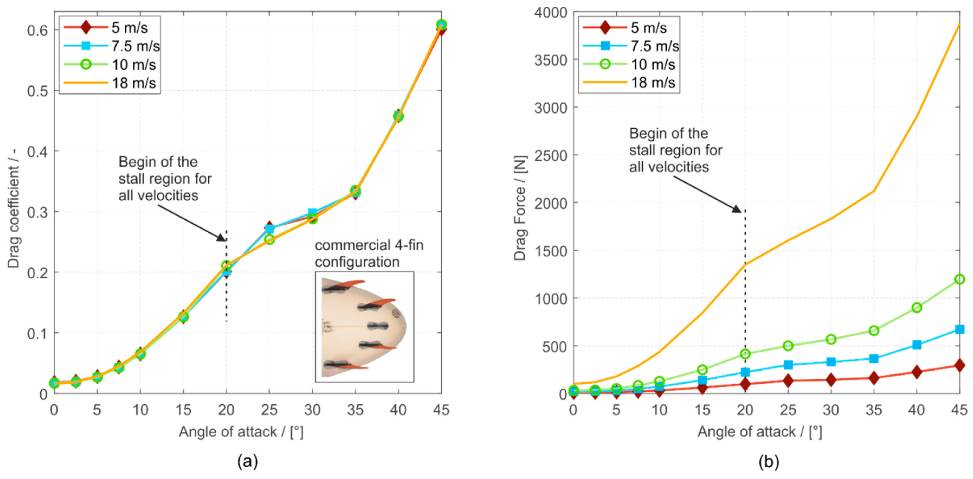
4.3. Lift and Drag for Four Different Inflow Velocities (5 m/s, 7.5 m/s, 10 m/s, and 18 m/s) at the Investigated 4-Fin
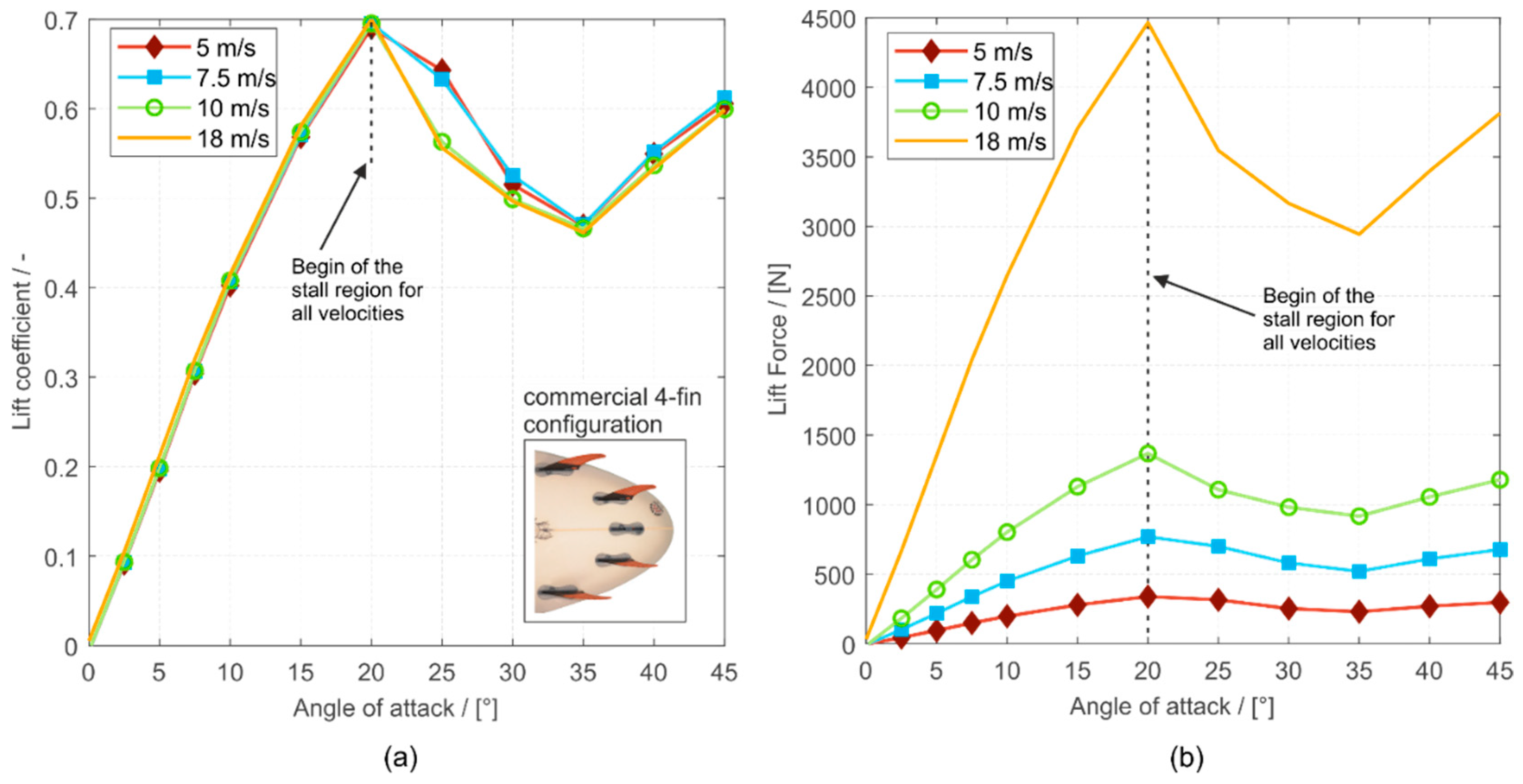
There are no significant differences between the lift and drag coefficients for different velocities over nearly the whole AoA, as previously found by [
13], which supports our Hypothesis 2. However, the lift and drag forces increase with increasing velocity, and the force fluctuations, which become dominant after stall [
11], will increase simultaneously. Therefore, the surfing control becomes more challenging for the surfer in higher velocities, as the stability decreases.
4.4. Rear Fin Position Study: Axial vs. Transverse Shift of the Rear Fins
Moving the rear fins in the transverse direction from the rail to the longitudinal axis of the surfboard implicate that:
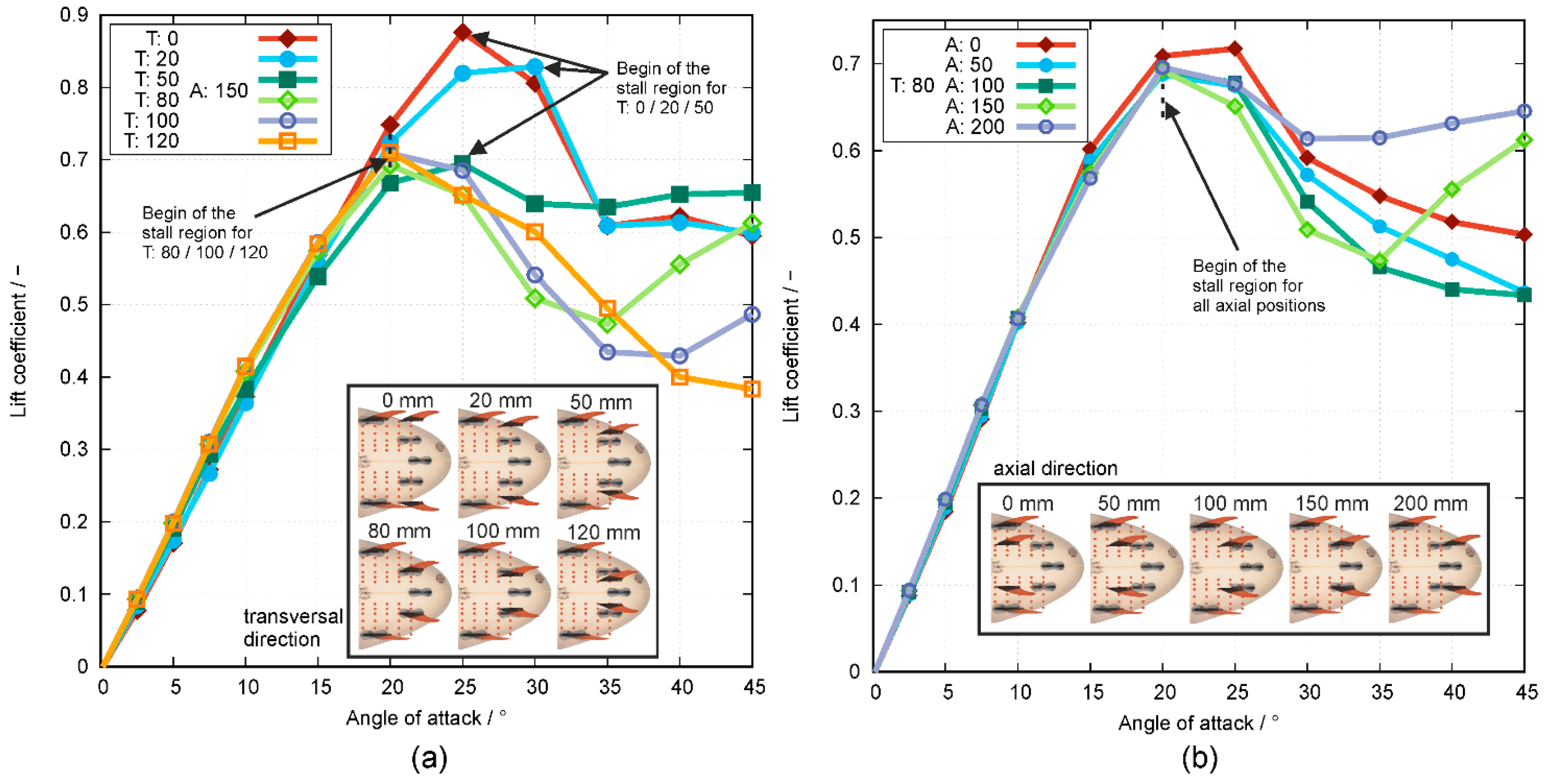
The stall point is moving from an AoA of 30° (T:0) to 20° (T:120),
the maximum of the lift coefficients decreases significantly from 0.87 (T:0) to approx. 0.7 (T:50–120), and
the lift coefficients also decrease in the range of high AoA of 30°–45°.
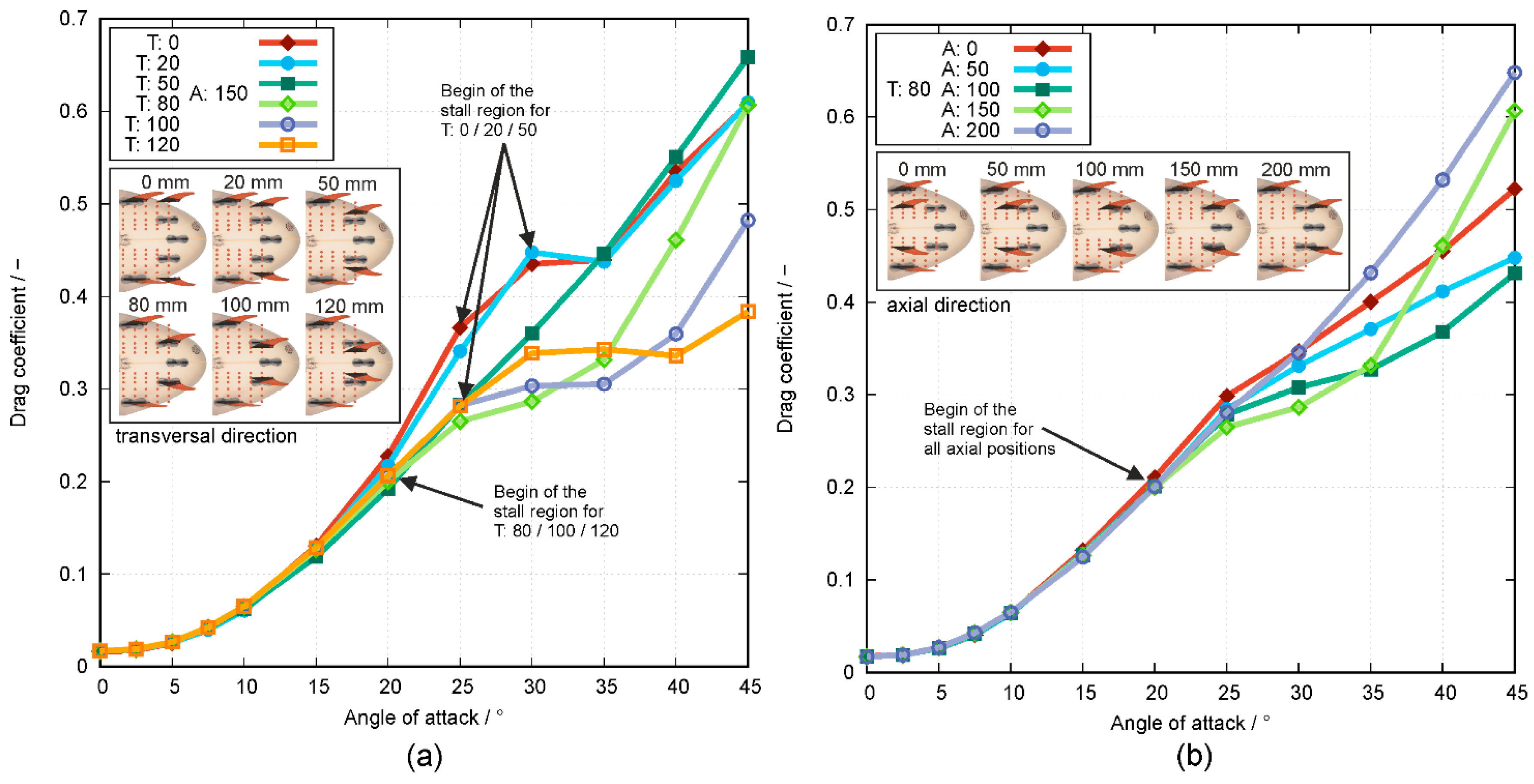
We assume that, at T:0 and T:20, the front and the rear fin of each side (outside and inside) act as one large fin. Therefore, these configurations can be seen as a two-fin configuration and therefore produce a higher lift force owing to the increased fin area (sum of front and rear fin at both rails). The corresponding stall points are located at AoA = 25° and 30°, which are higher compared to the positions of T > 20. Therefore, these two configurations can be surfed with greater stability up to a higher AoA before force fluctuations occur for positions T > 20. Furthermore, the rear OF is not shadowed by the front OF for AoAs up to 20°, as shown in
Figure 10a and
Figure 11.
Moving the rear fins in the axial direction toward the tail of the surfboard implicate that:
The stall point is moving from an AoA of 25° (A:0) to 20° (A:50–200),
the maximum lift coefficient decreases slightly from 0.72 (A:0) to 0.69 (A:50–200), and
the lift coefficients start to increase again at an AoA = 35° for the positions A:150 and A:200.
The rear fins at A:200, which is the position nearest to the tail, especially the rear OF, are not significantly disturbed by the wake of the front fins like in other fin configurations. Therefore, this configuration has no massive decrease in lift and can produce a high, nearly constant, lift coefficient at high AoA > 20° after stall occurs. However, on the other hand, position A:200 produces the highest drag coefficient at high AoAs. These two effects indicate a stable surfing condition due to the high lift and a constant lift force gradient but with a tendency to result in a more significant speed loss. Thus, the maneuverability and direction control may be more challenging. These findings in fin positioning support our Hypothesis 3.
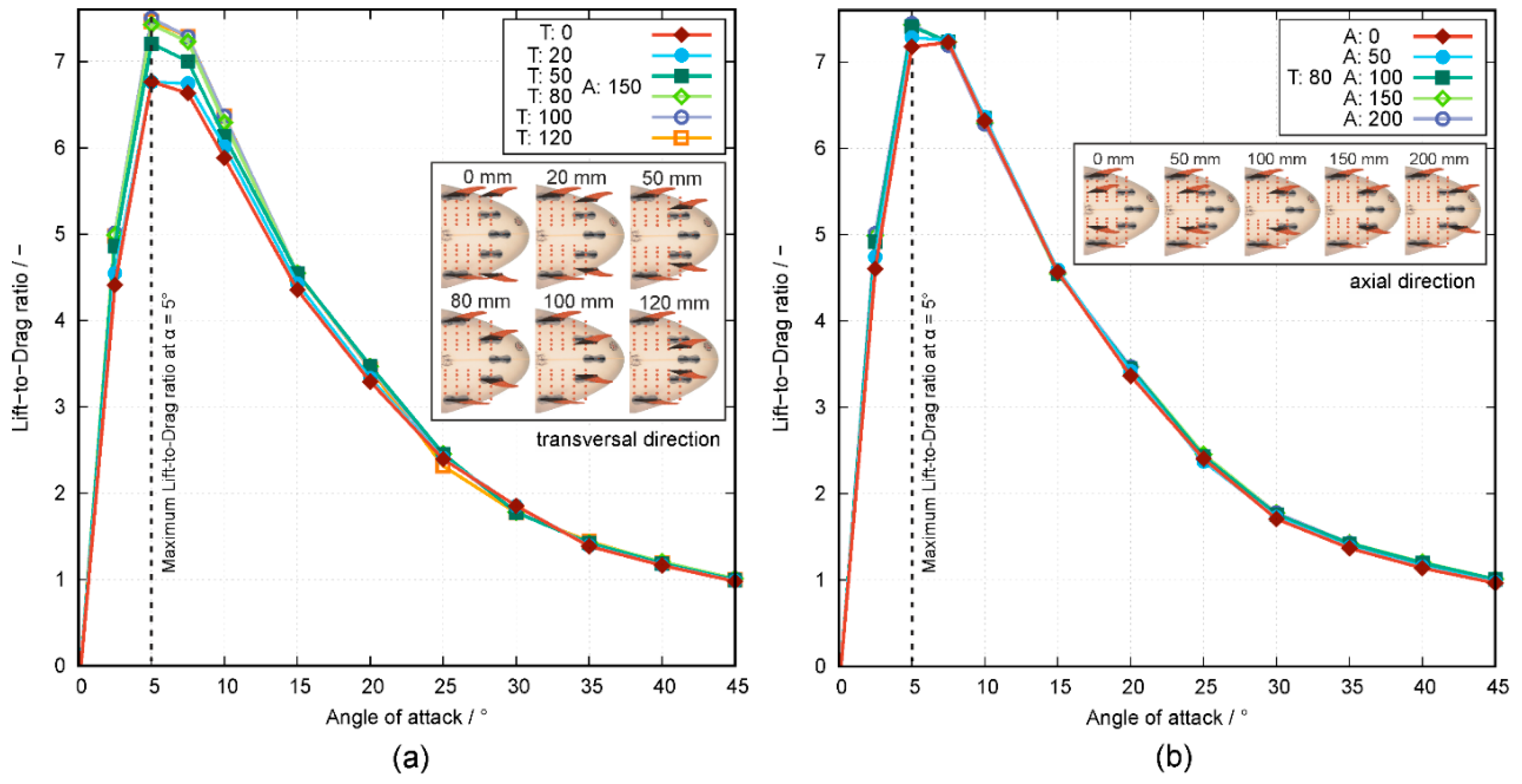
Furthermore, we suppose that if a shaper wants to create a 4-fin configuration at the surfboard that produces a high lift coefficient, one has to place the rear fins in flow direction behind the front fins, which generally corresponds to a position near the rails of the surfboard like position T:0 A:150 and T:20 A:150. If a shaper wants to have a high lift coefficient at high AoA, one has to place the rear fins near the tail of the surfboard like the positions T:80 A:200 or T:50 A:150. We also suppose that if a shaper wants to create a radical 4-fin configuration at his surfboard, which produces a low drag coefficient over the whole range of AoA, one has to place the rear fins at positions T:120 A:150 or T:80 A:100. If the shaper wants to set up a 4-fin configuration with a steadily increasing drag coefficient, one has to place the fins at positions T:50 A:150 or T:80 A:200. If a shaper wants to set up a 4-fin configuration with a high lift-to-drag ratio at an AoA of 5°, one has to choose the positions of T:80–120 A:150 or T:80 A:100–200.
4.5. Shortcomings
While importing the 3D model into STAR-CCM+, the board geometry was cut away, and just the four fins were placed into the simulation region. Therefore, we approximate the flat bottom wall of the simulation region as a surfboard, and, consequently, the numeric model represents no surfboard-fin interaction.
We do not simulate real surfing on the wave with a tilted surfboard where the fins are not always entirely in contact with the water.
Validating the simulated results with experimental data, not only from cognitional fields of application, is necessary, and experimental tests in a flow channel with the same setup as the numerical simulations are planned for the future.
5. Conclusions
This study investigated the hydrodynamic performance of the 4-fin configuration with both steady-state and time-dependent simulations. For the first time, a parameter study of the positions of the rear fins within a 4-fin configuration is performed. Additionally, the influence of four different inflow velocities, which represent small and big waves, on the lift and drag forces produced by the fins, is investigated. This study shows an evident and significant influence of the rear fin positioning and the inflow velocity towards the lift and drag performance characteristics. The following points provide a more detailed description of our findings:
The surfer has to apply much more work to perform a turn maneuver with a 4-fin configuration due to the higher lift forces and is losing more velocity during maneuvers because of the higher drag forces compared to a 3-fin configuration.
The investigated surfing velocity has nearly no effect on the lift and drag coefficients, but the lift and drag forces increase nonlinearly with increasing velocity.
At the 4-fin configuration, the front and rear fins of each side act like two large fins when the OFs and RFs are nearly aligned (T:0 A:150 and T:20 A:150) and therefore produce the highest lift forces with a later onset of force fluctuations.
The maximum of the lift-to-drag ratio increases while shifting the rear fins in the transverse direction toward the longitudinal axis of the surfboard with a fixed axial position.
Finally, the results indicate a significant impact of the fin positions on the lift and drag forces that significantly influence the speed-up and the maneuverability of the surfboard. Thus, this information is highly relevant for a surfboard design for different surf conditions, including big waves (speed-up) and small waves (maneuverability/tricks).
