1. Introduction
The cervical cytology test has become one of the most effective methods for early cervical cancer screening, and the production of cytological specimens is the prerequisite for accurately detecting lesions [
1,
2,
3,
4]. Several factors including the thickness of cell smears, the distribution of cells, and the number of cells will affect the clinical pathological diagnosis directly. Membrane liquid-based thin-layer cell production is a technique that applies the principle of mechanical, electronic, and fluid dynamic to the dispersion, filtration, transfer, and immobilization of cells [
5,
6]. This technique is able to disperse cell samples, remove non-diagnostic ingredients such as mucus, blood and other impurities in the sample, collect useful cells on a high-precision microporous membrane surface and finally transfer them to cell slides. The accuracy of clinical diagnosis can be improved significantly if the smears are evenly made, in intact shape, without cross infection, with clear background, and with densely distributed cells which are convenient for microscopic observation [
7,
8,
9,
10].
In recent years, Chinese hospitals have successively introduced foreign liquid-based thin-layer cell production devices. Nevertheless, it is still difficult to promote such applications in small and medium-sized hospitals, township hospitals, and community medical service stations due to their high prices and consumables. Some Chinese companies have developed some low-cost liquid-based thin-layer cell-making machines which change the cell break-up method of imported tablet machines from topspin to down-spin, with the aim of reducing the costs of production, research, and development. However, this method has a poor effect on breaking up cells, resulting in a low production satisfaction rate, further affecting the observation and diagnosis of doctors [
11,
12].
Based on the above discussions, there are still some limitations for the existing liquid-based thin-layer cell tableting machines: Firstly, the design of two robot arms [
13] (an unloading robot arm and a sampling robot arm) makes the structure complex and the instrument cost high. Secondly, the need to load and unload membranes manually not only reduces the degree of automation [
14], but also increases the opportunity of secondary pollution. Thirdly, the internal pressure control system of these machines is complex, which leads to higher costs and failure rates [
15,
16,
17,
18]. To handle these issues well, an effective membrane-based liquid-based thin-layer cell-making machine is presented in this study. After parameter calibration and testing, a new mechanical system and a new control system are designed through summarizing and absorbing the advantages and characteristics of instruments of the same type worldwide. Results show that the designed maker owns superior features in terms of production quality, automation degree and instrument cost.
2. Procedure and Structure
The membrane liquid-based thin layer cell production technology can be described as a processing procedure of the samples in storage solution. The schematic diagram of a multi-spectral imaging system based on a multi-channel narrow-band filter is shown as
Figure 1. Firstly, negative pressure and positive pressure are applied successively to ensure cells are absorbed on the outside of microporous membrane. Then, these cells are transferred to a glass carrier through positive pressure to form a thin layer with uniform thickness. The key steps and structure is shown as follows:
(1) Membrane cartridge [
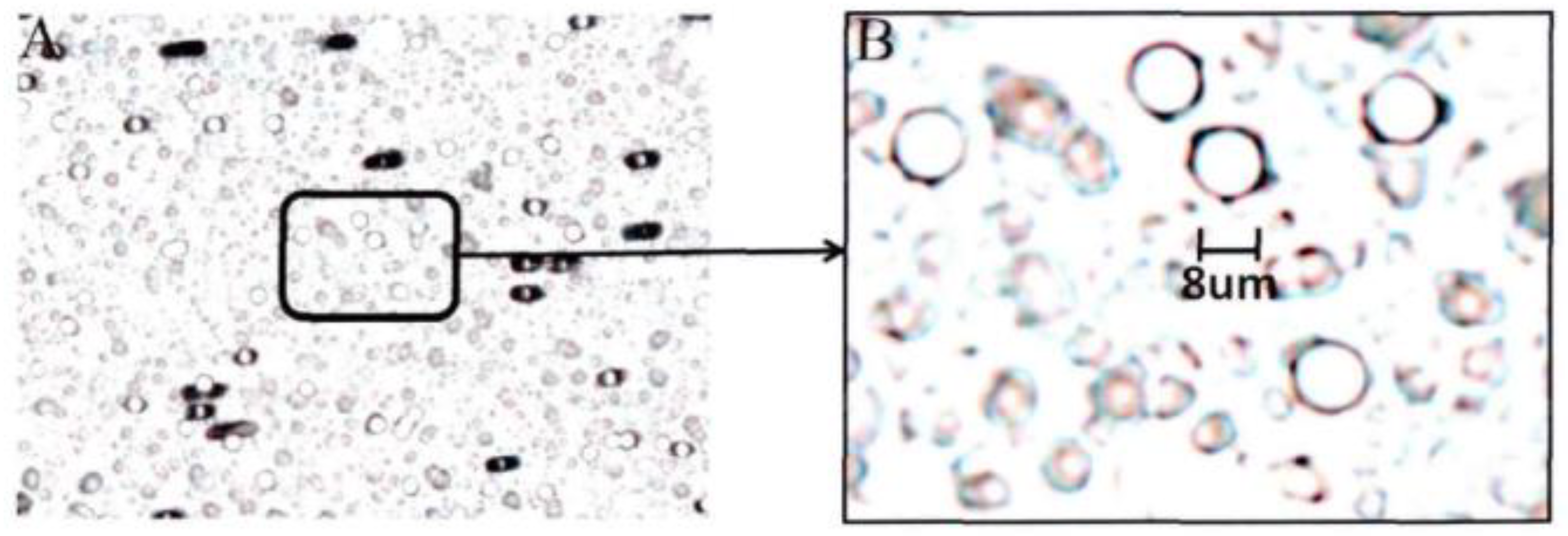
19]: the cell membrane cartridge is a cylinder with a diameter of 20 mm and a length of 55 mm. One side of it is open and the other side is welded to a microporous membrane. Microporous membrane processed by electron accelerator adopts the international standard, with a diameter of 20 mm, a thickness of 20 mm, an aperture of 8 mm, and 100,000 holes per square centimeter. The microporous membrane observed under electron microscope is shown as
Figure 2.
(2) Cell Dispersion [
20]: the filter cartridge is inserted into specimen bottle, and the filter cartridge collides strongly with the liquid in the specimen bottle through high-speed rotation. Then we disperse and separate the cells in the preservation solution which are overlapped and clumped together by mucus, inflammatory cells, and blood. The purpose of this step is to make the cells easily to be produced and observed.
(3) Cell collection [
21]: the open end of the filter cartridge is connected to a pressure control device. Under the action of negative pressure, the surface of microporous membrane begins to adsorb the cells in specimen solution. In this way, cells with large area are adsorbed, while the substance less than 8 um is filtered. The filter cartridge keeps rotating during adsorbing. Under the combined action of differential pressure, gravity, friction, centrifugal force and liquid resistance, large cell clusters, impurities, and overlapping cells among the surface-adsorbed cells cannot be adsorbed or they can fall off gradually. Finally, the effective cells shaped in uniform and thin layer are adsorbed on the surface of the microporous membrane.
(4) Cell transfer: cells are transferred from the surface of microporous membrane to the attached slide depending on the natural attachment characteristics of cells and the electrochemical properties of slides. Compared with the microporous membranes, slides have more binding force to cells. In this step, a weak positive air pressure is applied behind the microporous membrane to strengthen the cell transfer, so that a uniform and thin layer of cells can be formed on the glass slide.
(5) Unloading membrane cartridge and slide: when the process of cell transfer is completed, the filter cartridge is unloaded by manual or mechanical means, and the slide is immediately placed in a fixed solution bottle for wet fixation.
3. System Design
This section mainly includes two parts: mechanical structure and control system. Specifically, the first part focuses on introducing and analyzing the functions and implementation methods of several key components. The second part explains the design of both hardware and software, and also describes how to realize the motion feedback and control of mechanical components, the measurement and adjustment of pressure system, as well as the real-time information interaction function of the human–machine interface.
3.1. Mechanical Structure Design
The main objects that an automatic production machine needs to operate are filter cartridge, specimen bottle and slide. Further analysis shows that the movement of all operations can be realized in a two-dimensional plane, and the multiple stations can be arranged in one plane. The needs for movement can be met by designing a few more single or two-dimensional manipulators [
22,
23]. In this paper, a polar coordinate manipulator is designed. For this manipulator, the origin is its rotating central axis and all the stations are arranged on a polar coordinate plane. All operational requirements can be satisfied by controlling the rotation and radial movement of the manipulator. With this solution, the cost can be reduced and more work stations can be provided. In the aspect of motion control, the interpolation motion can also be performed to complete more complicated motion functions, i.e., slides unload is carried out by using a simple linear interpolation movement.
Figure 3 is a schematic view of the mechanical structure of the production machine. For this production machine, the robotic arm could efficiently move in a two-dimensional plane to realize loading and unloading of the membrane tube. The operating head is connected to a pressure source to provide positive pressure for adsorbing cells and negative pressure for transferring cells. During the slide unloading process, operating head can provide enough driving force to promote the slide transfer.
3.1.1. Production Workflow
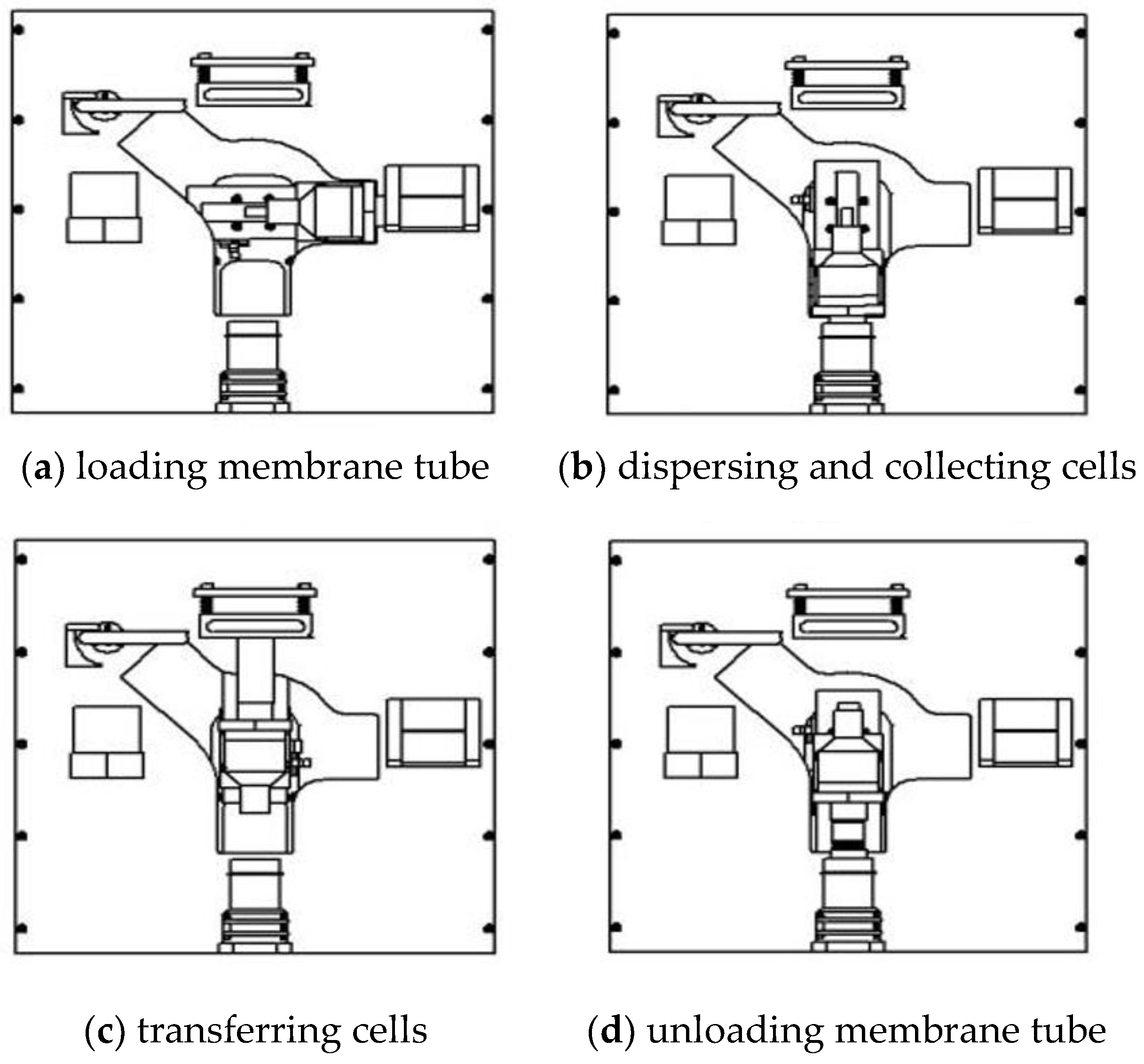
According to the above work plan and the steps of production, detailed actual working flow is shown in
Figure 4:
(1) Loading membrane tube (
Figure 4a): the manipulator is first turned to horizontal position and the arm is moved to end right. Then the operation head is inserted into the preset membrane cartridge in membrane holder. Load the film cartridge, and return the radial of the manipulator to zero after completion.
(2) Dispersing and collecting cells (
Figure 4b): the manipulator is turned to a vertical downward position and the arm moved end down. The operation head and the membrane cartridge are inserted into the specimen bottle. Perform cell dispersion and collection.
(3) Transferring cells (
Figure 4c): the manipulator is turned to vertical upward position and the arm moved end up. The membrane tube is attached to the slide, and the cells transferred to the slide.
(4) Unloading membrane tube (
Figure 4d): the arm is turned to vertical downward position and the arm end moved down. Here, the membrane tube is blown out by large positive air pressure and recycled to the sample bottle for disposal.
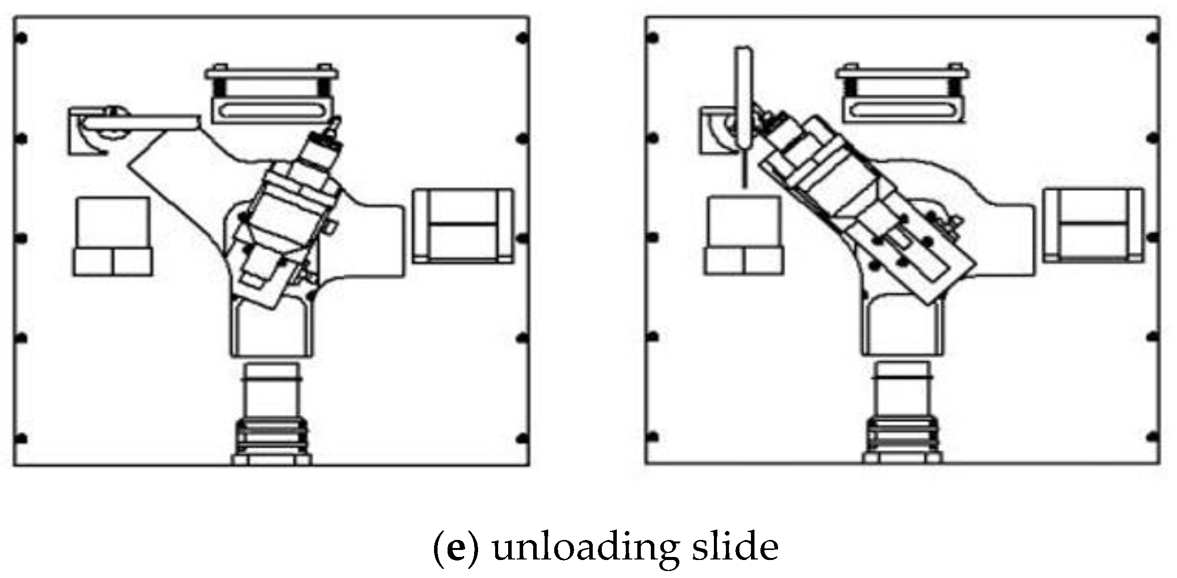
(5) Unloading slide (
Figure 4e): the arm is turned to the upper right position, and the arm end moved forward to the initial position of the unloading. The manipulator performs a linear interpolation movement at this time, and the control lever moves the slide to unloading device. When the arm end moves forward, the lever pushes the unloading device to vertical position, and the slide falls under the action of gravity.
3.1.2. Operating Head Design
There are two ways of dispersing in the process of cell dispersion. To be specific, the first method is rotating the membrane tube. In this way, the sample bottle is fixed, and the membrane tube rotates at high speed inside, thereby the cells are broken up through intense collision. The other method is rotating the sample bottle. In this case, the membrane tube is fixed, and the sample bottle rotates at high speed to drive the liquid in the bottle to rotate. Then cells are broken up through the collision between the membrane tube and the liquid. Among them, the first method has a better effect of dispersing cells and relatively stable quality of production, but its structure is complicated. In contrast, the second method is simple in structure and low in cost, but the effect of cell dispersion in this way is relatively poor. Moreover, cells cannot be completely dispersed no matter in which way. There are always some cell clumps should be removed as much as possible during the collection process.
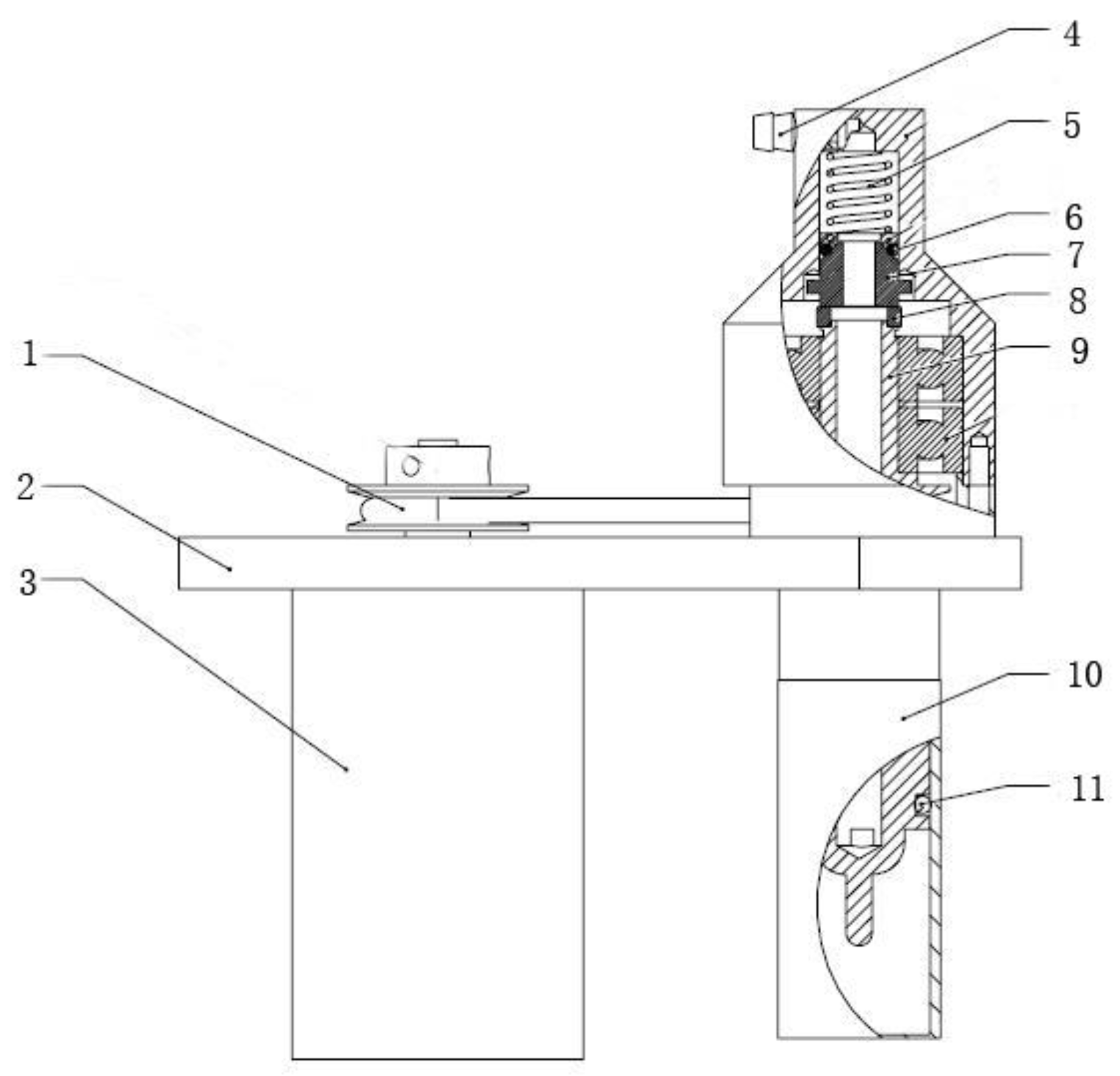
The operating head structure designed in this paper is shown in
Figure 5. The direct current brushless motor uses a flexible belt to drive the membrane tube to rotate. A rotary dynamic seal component is designed to ensure the continuous rotation of membrane tube when collecting cells. This component adopts silicon carbide material with high hardness and high wear resistance as a moving ring, and uses graphite material with self-lubricating function as static ring. The pre-compression spring presses the moving ring and the static ring tightly, and a good dynamic sealing surface can be formed since the contact surface is a polished surface, the friction is small, and the sealing is good. Furthermore, the preload spring can also automatically compensate for the thickness of worn material, and it can increase the service life of the dynamic seal component as well.
3.1.3. Pressure Control System
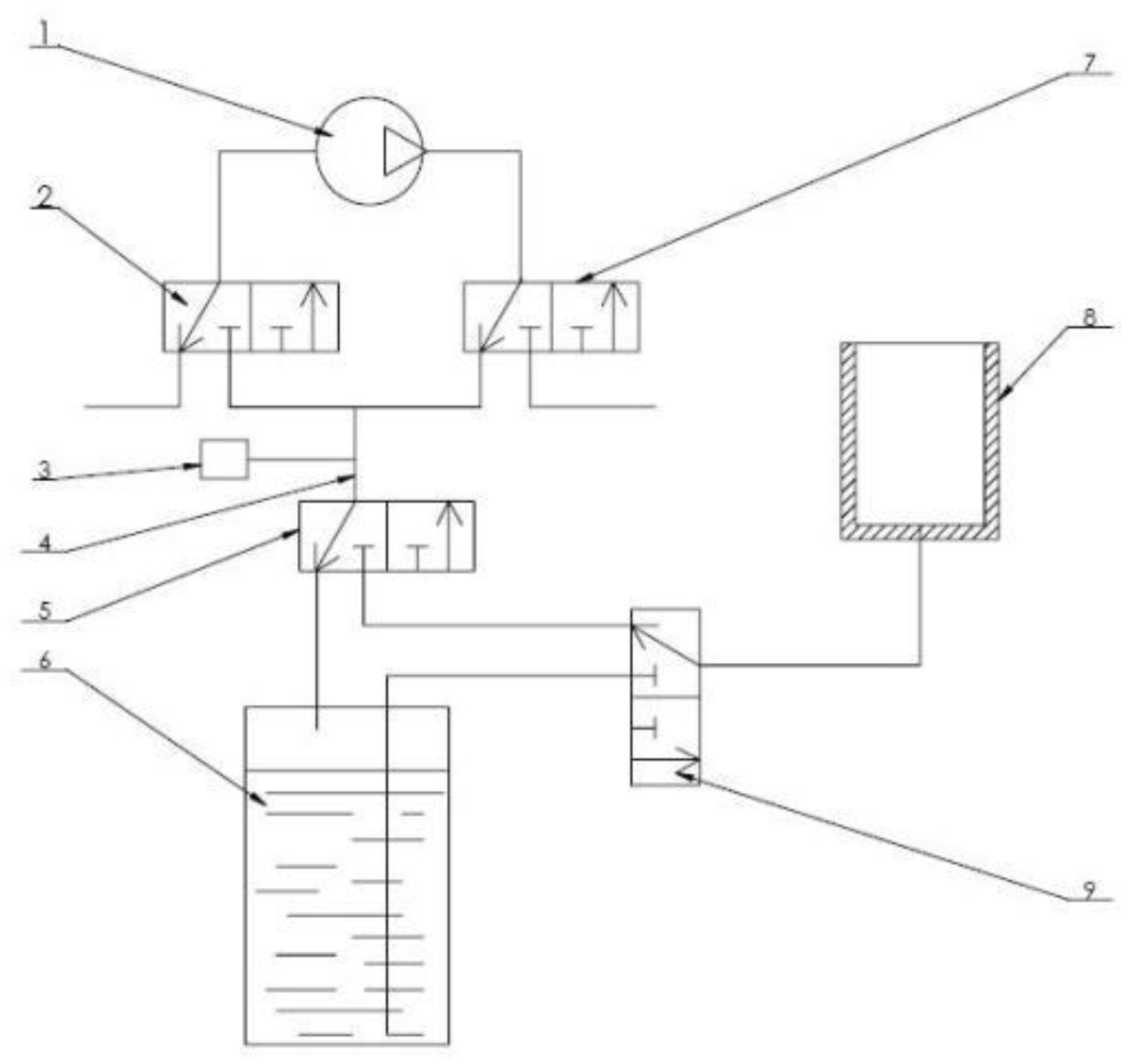
The air pressure control system designed in this paper is shown as
Figure 6. A vacuum pump, four two-position three-way solenoid valves, and a closed waste cylinder are used in this system to realize the free cutover from the modes of operation including pumping, exhausting, discharging waste liquid and so on. The vacuum pump inlet can provide negative pressure, and the outlet port can provide positive pressure. Among them, No. 1 and No. 2 solenoid valves are used to switch the type of air source (positive or negative pressure) entering the main air path. When collecting cells, negative pressure needs to be provided in membrane cylinder. The filtered waste liquid in it cannot be directly sucked into the vacuum air pump, but needs to be discharged to a sealed waste liquid tank. When transferring cells, positive pressure is required in membrane tube. At this time, gas source should be directly connected and provided by air pump. No. 3 and No. 4 solenoid valves are used to switch the membrane tube connection. Furthermore, a pressure sensor is also provided in the pipeline to monitor and feedback the pressure in pipeline in real time. Through controller conversion and proportion integration differentiation (PID) calculation, the air pressure is controlled at set value through adjusting the speed of the air pump.
3.2. Measurement and Control System Design
3.2.1. Hardware Design
The hardware design schematic of the liquid-based thin layer cell production machine is shown in
Figure 7. The core controller uses C8051f006 single chip microcomputer and programmable logic device EPM7128STC100. Their address bus and data bus communicate with each other, receive the data measured by the sensor, control the movement of the actuator, and perform human–computer interaction communication. The hardware design can be divided into following modules according to different function types:
(1) Motion control module: the polar coordinate manipulator uses two stepping motors, and the Senchuang two-phase hybrid stepping motor 42BYG250A is used in this case. The subdivision driver matched with it is SH-20403. The single chip microcomputer and the complex programmable logic device (CPLD) cooperate to generate the direction and pulse signal to guarantee the rotation of stepping motor. They also provide the stepping motor subdivision driver to control the stepping motor to complete specified actions. Since the operation of the stepper motor requires a mechanical origin as reference, a limit signal is added to this design, and this signal is provided by on-beam photoelectric switch moc70T2.
(2) Pressure control drive module: the inside of the vacuum pump is a brushless direct current motor. The motor is driven by a motor drive chip L298N which is a high voltage and high current dual full bridge driver contains two sets of H-bridges. The enable end of chip modulates wave signal by inputting pulse width, and it also adjusts the different duty cycles to control the speed of direct current motor to further control the air pressure generated by air pump. Moreover, the pressure control system also needs to operate four solenoid valves with the voltage of 12 V. Here, the Darlington tube TIP122 is used to form drive circuit. Each solenoid valve is used in one group, and a total of 4 sets are set. The pin is fed with a transistor transistor logic (TTL) level to control solenoid valve to be turned on or off.
(3) Sensor module: Air pressure sensor is the most important sensor for this instrument. Here, the MPX2050GP silicon piezoresistive pressure sensor is used for automatic temperature compensation and calibration, and it also provides high-precision linear output. Since the output voltage value is very small, it is necessary to amplify the voltage during use. The AD620 is a low cost, high-precision instrumentation amplifier with a magnification of 1 to 1000 and it is easy to be used. Before being output, the air pressure sensor signal is amplified by the AD620, then it enters the analog to digital converter (AD) conversion pin of single chip microcomputer, and the real-time air pressure value is measured after the conversion of single chip microcomputer. A liquid level sensor is also used in this instrument to detect whether the liquid level of the waste liquid tank is out of limits. A reflective photoelectric switch sensor is placed to detect if the membrane tube is properly loaded and unloaded. In the events of abnormality, the sensor signal causes program to enter an interrupt and the the error protection mechanism starts up.
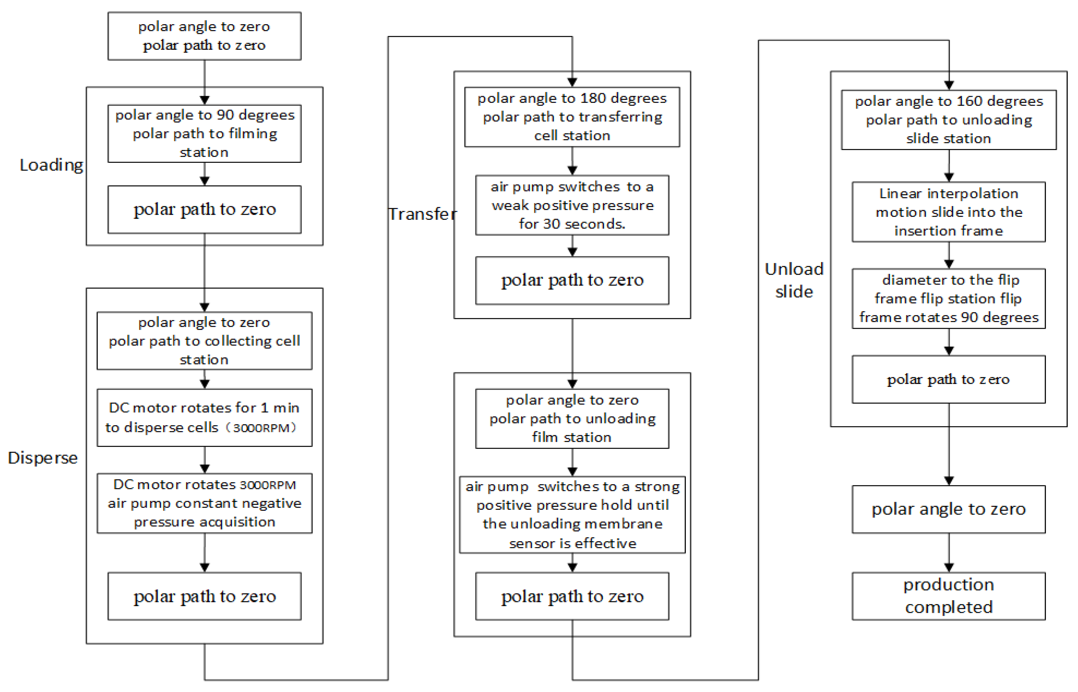
(4) Human–computer interaction module: the production flow chart is shown in
Figure 8. This instrument performs human–computer interaction through a liquid crystal touch screen which is a modular integrated product. Manufacturers provide interface development softwares and communication protocols to facilitate rapid development of users. The liquid crystal display (LCD) screen and the single chip microcomputer can communicate just through the universal asynchronous receiver/transmitter (UART) serial port connection, so the cumbersome steps of graphical user interface (GUI) development can be eliminated.
3.2.2. Software Design
The software system is developed based on the C language environment of single chip microcomputer. In this process, the modular design thinking is adopted. The functions as well as interfaces of each functional module are designed respectively and packaged after passing the test. These models include the drive module of the stepper motor, the air pressure acquisition module, the liquid crystal communication and decoding module, the interpolation calculation module and so on. The user application calls these underlying driver functions in an orderly manner and performs corresponding operations according to the designed software workflow [
24,
25,
26].
(1) Production process: the mechanical workflow is described in
Section 2. This part explains the specific operation of the executive agencies in software. The main operation is the control of the polar coordinate manipulator, including using rotary stepper motor to control the polar angle of manipulator, and using the linear stepper motor to control the polar path of manipulator. In this application, the zero point of the polar angle is in vertical downward direction, and the zero point of the polar path is at the zero point in radial direction. Each station has its corresponding polar coordinate value. Through testing and calibration, these values can be converted into pulse number coordinates of the motors relative to their respective zero points. Then, the arm end moves to the specified position by sending the number of coordinate pulses from the software. In another method, the Pulse Width Modulation (PWM) control method is adopted for the control of direct current motor, and the integrated PWM generation module is provided by the single chip microcomputer of C8051F series. The pulse width modulated waveforms with specified duty cycles can be generated automatically by changing the parameter value in the module. The higher the duty cycle, the faster the speed, then the corresponding breaking force of dispersing motor and the pressure of the air pump become larger as well.
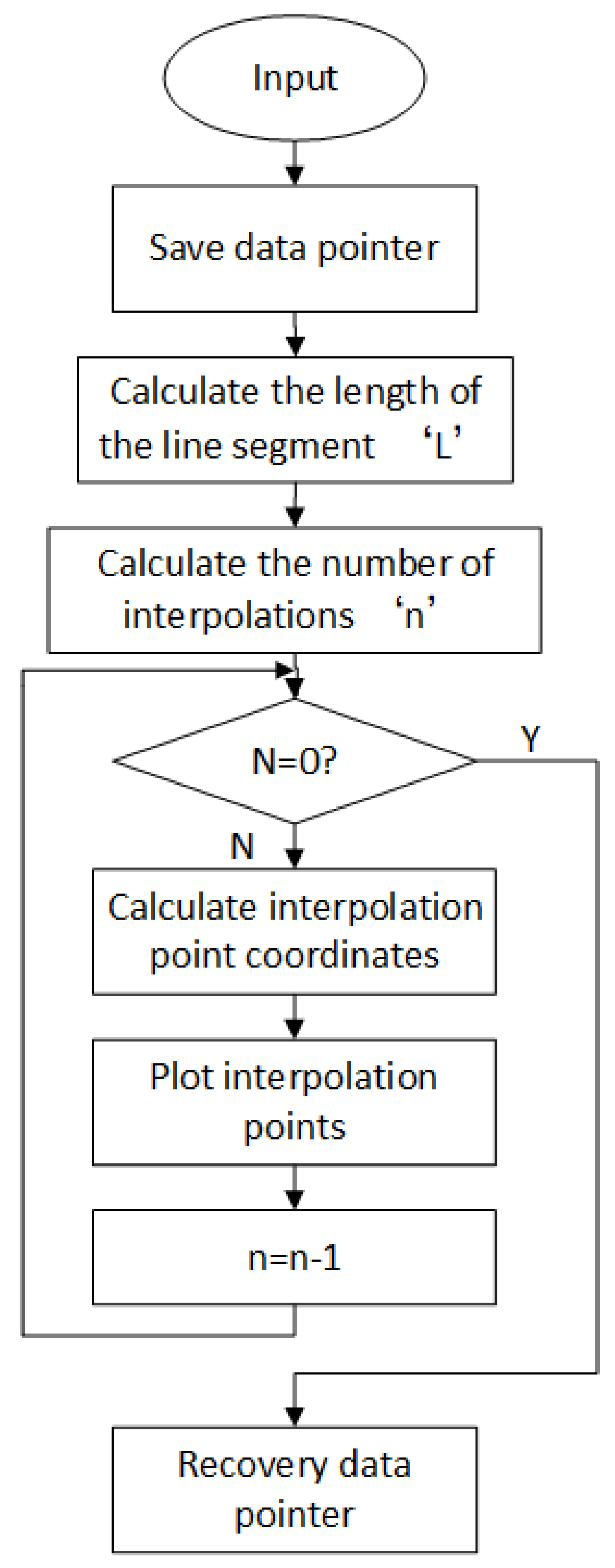
Figure 9 is a schematic view of the polar coordinate linear interpolation process.
(2) Polar coordinate interpolation algorithm [
27]: the slide is placed horizontally on the slide holder. When the slide is unloaded, move the lever on manipulator to push the slide, then the slide is panned to the inside of flip frame on the left. In order to prevent the mechanical interference and guarantee the smooth promotion during this pushing process, it is necessary to control the lever to make straight line operation. In the case of polar coordinates, the linear interpolation algorithm is required for this linear motion.
For linear interpolation, firstly the coordinate system ought to be converted to the cartesian type. Based on the start p oint
and the end point
of the interpolation, the length
of the line can be calculated as:
According to the resolution delta of the polar coordinate manipulator, the number of steps (
n) required for interpolation is calculated as:
Here
n can be seen as a judging condition for the completion of interpolation. The coordinates of the end point of the line can be expressed through the coordinates of the starting point:
In the equation,
and
are the angles between the line and
and
axes as:
During the interpolation process, the
th interpolation is advanced from the starting point to the end point by
length, and advanced on the
and
axes by
and
length respectively. So the resulting coordinates are:
According to the interpolation process of the numerical control system and the above interpolation calculation formula. The interpolation program can be programmed according to the flow chart. Since the imputed line is fixed, the program does not have to spend a lot of resources to calculate when it is executed each time. By using the array to record the number of pulses of each axis motor for each interpolation in the complete interpolation process, it is merely necessary load the parameters in the array through cycle lookup when running.
4. Experiments and Discussions
4.1. Platform
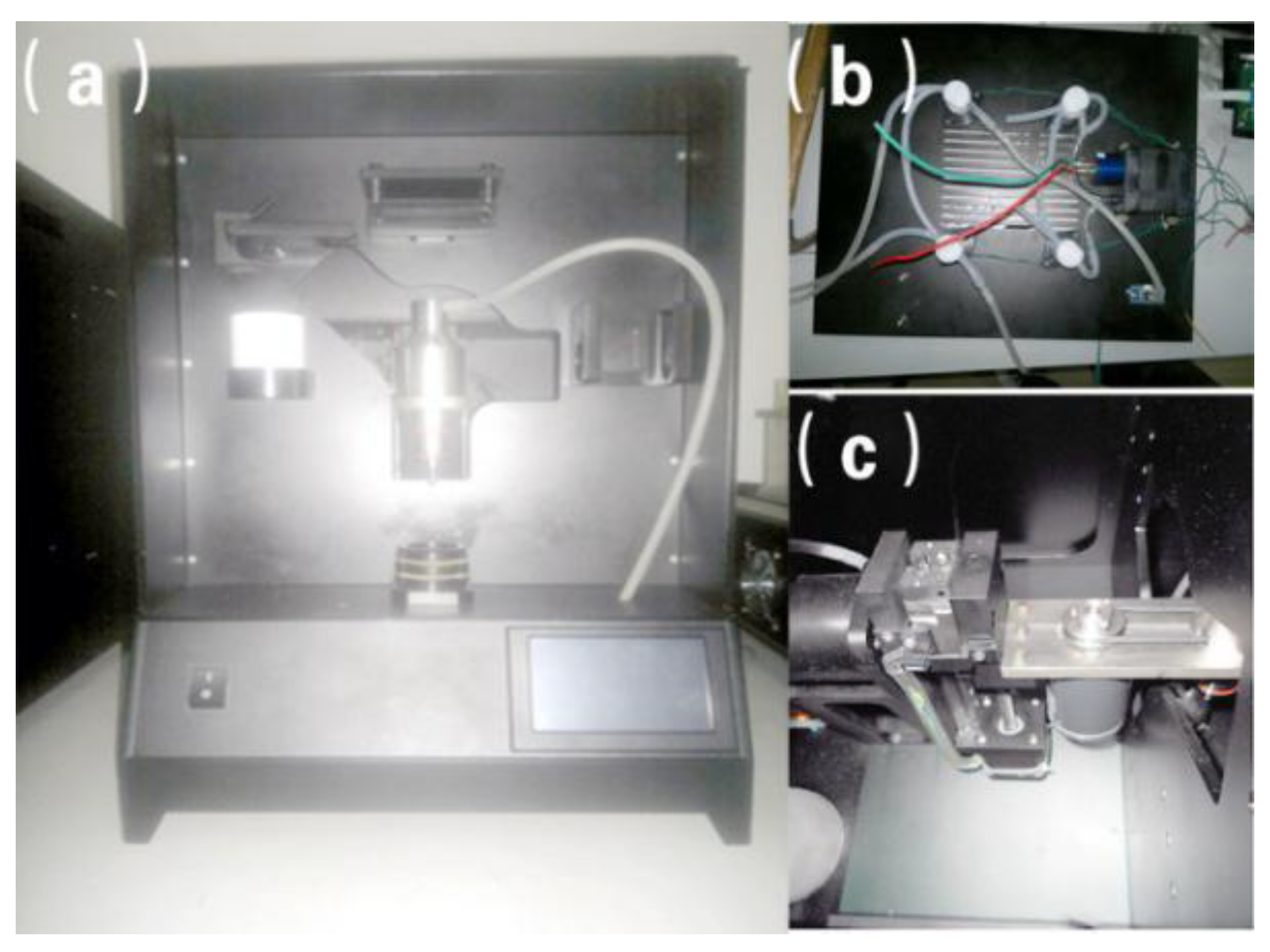
The physical diagram of developed membrane-based liquid-based thin-layer cell tableting machine is shown in
Figure 10.
Figure 10a is the front side of the working substrate with the size of 330 mm × 330 mm.
Figure 10b represents the designed pressure control system.
Figure 10c show the physical map of the polar coordinate robot arm and LCD interface respectively. It can be observed that all stations are arranged on the working substrate compactly. The pressure control system is composed of an electromagnetic valve, a vacuum pump and the pressure sensors. All these components are connected by simple pipes, resulting in a reliable maintenance environment. Normal operations including loading the film barrel, dispersing the collected cells, transferring cells, and unloading the film tube are all carried out by using the polar coordinate robot arm. For the LCD interface, after manually loading the film tube, the production can be completed automatically by pressing the RUN button. Besides, the corresponding parameters can be also updated and stored in the developed cell film maker. Experimental results illustrate that the total time for the maker to produce a film is just 2.5 min. After 200 days of a real-world test, this cell film maker still presented a satisfactory stability and it has been successfully applied in a Wuhan technology company for the applications of cervical cytology tests and early cervical cancer screening.
4.2. Production Quality
4.2.1. Visual Observation Results
A high-quality film needs to satisfy several main criteria as: (1) the film is refreshing with distinct layers and no bubbles. (2) the cell nucleus is clear under the microscope environment. (3) To help with diagnosis, the nucleus and cytoplasm should be clear under the microscope. The keratinocytes and non-keratinocytes should also be clearly visible. Moreover, the satisfactory standard for production is as follows: according to the production field of view (3.15 cm2) adopted by national standard, more than 5000 intact and clear squamous epithelial cells are necessary. In order to verify whether the production machine meets the requirement, a large number of tests and calibrations are performed before the parameters are determined. Finally, several key parameters are selected, including the rotating speed of dissipate motor is 3000 RPM, the adsorption pressure is 90 kpa, the speed of adsorption is 1000 RPM, the transfer pressure is 140 kpa, and the transfer time is 30 s.
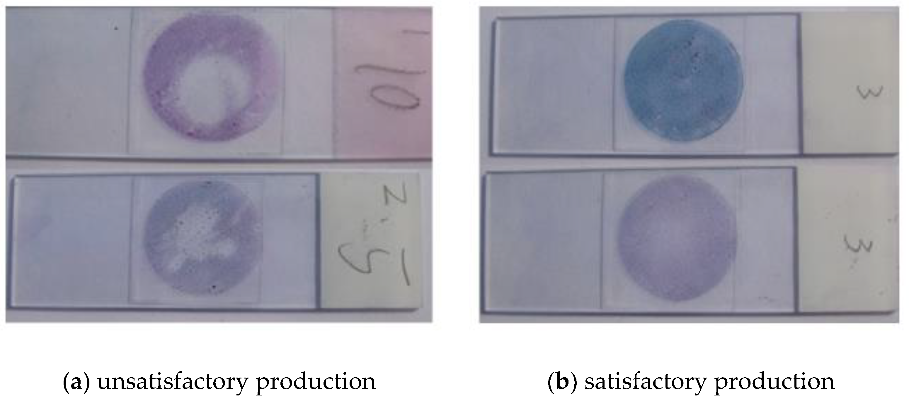
Although the appropriate parameters are selected, specimen satisfaction often varies due to the effects of specimen quality difference, ambient temperature and humidity in practical application. A typical bad sample is shown in
Figure 11a. The smear cells are unevenly distributed, and the cells around the smear are too much or too thick. In some other areas, the cells may be missing or too thick. This kind of unsatisfactory production should be avoided as much as possible.
Figure 11b shows the satisfactory preparation observed under naked eyes. These cells have good tiling, uniform thickness, and dense distribution.
4.2.2. Microscopic Observation
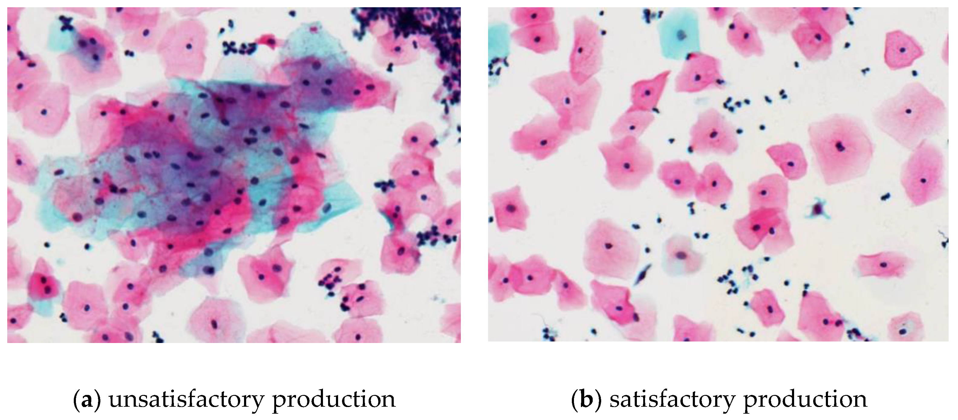
Under the microscope of 200 times, the phenomenoa of cell clumps, cell stacking, mucus and impurities in group for the unsatisfactory production are illustrated in
Figure 12a. Moreover, some cells have obvious pyknosis, the red blood cells or inflammatory cells are polluted too much, and the staining is also not bright enough. These phenomena badly affect the observation of squamous epithelial cells. Although it is unavoidable, if too many such phenomena affect the observation for more than 75% of the cells, it can be considered that the production is not satisfactory and should be strictly controlled. Conversely, the good-quality films should be in a good shape, evenly distributed, and have clear background.
Figure 12b represents the results of satisfactory production. They should also act with less overlap, accumulation and impurity distribution. The excessive mass of cell clumps and mucus impurities are related to the strength of dispersion lysis, and the cell stack is caused by negative pressure of adsorption when collecting cells. Adjusting the instrument parameters as appropriate can effectively control the frequency of such kind of phenomena.
4.3. Comparative Experiment
Limited by uncontrollable factors in the process of material extraction, film production and dyeing, the satisfaction of any instrument or any production method is unlikely to reach 100%. It can be considered acceptable when the satisfaction rate reaches a certain value. In order to test whether the production machine developed in this paper meets or exceeds the quality of existing instruments, two types of production machines are selected for comparison, including the imported ThinPrep2000 and a Chinese machine of sample bottle rotary type. The specimens with a total of more than 1000 cases are sourced from Hubei Provincial Maternal and Child Health Hospital Gynecology Clinic which is a partner of Wuhan Heer Co., Ltd. Three production machines are used to make the films in three batches. In this experiment, the criteria for satisfactory specimen evaluation is: the number of squamous epithelial cells with well-preserved morphology on the entire slide are more than 5000. In comparison, the criteria for unsatisfactory specimen is: there are less than 5000 cells, or there are more than 75% of squamous epithelial cells cannot be observed due to the factors such as blood, mucus, excessive cell overlap, or contamination. The method of estimating the number of cells is: firstly observe at least 10 fields of view with a 40× field of view in the central zone of smear, then estimate the average number of cells per field of view. When encountering a blank area, the percentage of these missing cell areas should be estimated. The actual test results are shown in
Table 1 below.
Unsatisfactory specimens include insufficient cell mass and excess impurities. The ratio of insufficient cells is listed separately in the table to compare the efficiency of cell collection and transfer. First of all, the imported model ThinPrep2000 has the highest satisfaction rate, and the insufficient amount of cells in the unsatisfactory specimens accounts for only 1.7%, indicating that the number of cells collected in this machine is sufficient, the success rate of metastatic cells is high enough, and the empty film rate is low. Secondly, the satisfaction rate of the Chinese machine is 85.1% which is the lowest, and the proportion of insufficient cells is 5.6%, indicating that the machine has cells missing and cell loss during the process of collecting and transferring cells. Finally, the production machine developed in this paper has a lower satisfaction rate than the imported machine, but the proportion of insufficient amount of cells is relatively small. The reason may be that this developed machine uses the same membrane rotation method as the imported machine to break up and collect cells, and this method is more efficient. In summary, the overall evaluation of the performance of the production machine developed in this paper is roughly between the performance of imported machines and most Chinese machines. There is room for improvement, but currently it has met the practical needs.
5. Conclusions
For the membrane liquid-based cell preparation machine, in order to solve the shortcomings of the existing product structure such as the low utilization rate of the robotic arm and the low efficiency of cell collection, a polar coordinated robotic arm and a new working scheme have been designed in this study to increase the degree of automation. Moreover, a novel dynamic sealing operation head and pressure control system are designed to improve the cell collection effect. Experimental results show that the proposed machine has a compact structure, stable performance, and high production satisfaction rate, which are suitable for real cell film-making applications. During the preparation process, cells and impurities are separated mainly by chemical lysis and mechanical agitation. The chemical lysis ability and mechanical agitation intensity of liquid-based cytology consumables from different manufacturers are different. If the reagents in the preservation solution have insufficient chemical lysis ability, cell clumps, blood and mucus cannot be decomposed well, causing blood or mucus to block the filter membrane in the specimen. The quality of film production is affected by many factors. This article starts with the research of the instrument and completes the development and verification of the entire equipment. Further works would focus on in depth analyzing several key elements in cell film-making process such as the cell preservation solution, microporous filter membranes, and adhesive slides.
Author Contributions
The contributions of each author are as follows: conceptualization, methodology, writing-original draft preparation R.F.; data curation, L.Z.; writing-review and editing, F.Y. All authors have read and agreed to the published version of the manuscript.
Funding
This research received no external funding.
Acknowledgments
The authors would like to acknowledge Wuhan Heer Co., Ltd. for help in providing many cases.
Conflicts of Interest
The authors declare no conflict of interest.
Abbreviations
| PID | proportion integration differentiation |
| PWM | Pulse Width Modulation |
| CPLD | complex programmable logic device |
| TTL | transistor transistor logic |
| AD | analog to digital converter |
| LCD | liquid crystal display |
| UART | universal asynchronous receiver/transmitter |
| GUI | graphical user interface |
| abscissa of start point |
| ordinate of start point |
| abscissa of end point |
| ordinate of end point |
| L | length of the line from start point to end point |
| α | cosine of line L and axes |
| β | cosine of line L and axes |
| resolution delta of polar coordinate manipulator |
| abscissa of the ith interpolation |
| ordinate of the ith interpolation |
References
- Wan, T.; Xu, S.; Sang, C.; Jin, Y.; Qin, Z. Accurate segmentation of overlapping cells in cervical cytology with deep convolutional neural networks. Neurocomputing 2019, 365, 157–170. [Google Scholar] [CrossRef]
- Tanaka, Y.; Ueda, Y.; Kakubari, R.; Kakuda, M.; Kubota, S.; Matsuzaki, S.; Okazawa, A.; Egawa-Takata, T.; Matsuzaki, S.; Kobayashi, E.; et al. Histologic correlation between smartphone and coloposcopic findings in patients with abnormal cervical cytology: Experiences in a tertiary referral hospital. Am. J. Obstet. Gynecol. 2019, 221, 241.e1–241.e6. [Google Scholar] [CrossRef] [PubMed]
- Al-Nourhji, O.; Dermawan, J.K.; Booth, C.N.; Underwood, D.; Abdul-Karim, F.W. Role of ThinPrep liquid-based cytology in evaluation of the endocervical canal in patients with abnormal cervical screening. J. Am. Soc. Cytopathol. 2019, 8, 278–283. [Google Scholar] [CrossRef] [PubMed]
- Chen, H.; Yang, L.; Li, L.; Li, M.; Chen, Z. An efficient cervical disease diagnosis approach using segmented images and cytology reporting. Cogn. Syst. Res. 2019, 58, 265–277. [Google Scholar] [CrossRef]
- Chaiboonchoe, A.; Khraiwesh, B.; Murali, C.; Baig, B.; El-Awady, R.; Tarazi, H.; Alzahmi, A.; Nelson, D.R.; Greish, Y.E.; Ramadan, W.; et al. Safranal induces DNA double-strand breakage and ER-stress-mediated cell death in hepatocellular carcinoma cells. Sci. Rep. 2018, 8, 16951. [Google Scholar]
- Palazon, F.; Pérez-del-Rey, D.; Dänekamp, B.; Dreessen, C.; Sessolo, M.; Boix, P.P.; Bolink, H.J. Room-Temperature Cubic Phase Crystallization and High Stability of Vacuum-Deposited Methylammonium Lead Triiodide Thin Films for High-Efficiency Solar Cells. Adv. Mater. 2019, 31, 1902692. [Google Scholar] [CrossRef]
- Zimmermann, J.; Jesse, S.; Kassubek, J.; Pinkhardt, E.; Ludolph, A.C. Differential diagnosis of peripheral facial nerve palsy: A retrospective clinical, MRI and CSF-based study. J. Neurol. 2019, 266, 2488–2494. [Google Scholar] [CrossRef]
- Zhang, C.; Li, H.; Guo, X.; Civilini, E.; Malik, K.; Wang, F. Clinical Diagnosis and Treatment of Internal Jugular Venous Aneurysms. Ann. Vasc. Surg. 2020, 62, 497.e7–497.e12. [Google Scholar] [CrossRef]
- Sparchez, Z.; Mocan, T.; Hagiu, C.; Kacso, G.; Zaharie, T.; Rusu, I.; Hajjar, N.A.; Leucuta, D.C.; Sparchez, M. Real-Time Contrast-Enhanced–Guided Biopsy Compared with Conventional Ultrasound–Guided Biopsy in the Diagnosis of Hepatic Tumors on a Background of Advanced Chronic Liver Disease: A Prospective, Randomized, Clinical Trial. Ultrasound Med. Biol. 2019, 45, 2915–2924. [Google Scholar] [CrossRef]
- Medson, K.; Vargas-Paris, R.; Rogberg, A.N.; Sigbergsdottir, A.; Nyrén, S.; Lindholm, P. Primary diagnosis of pulmonary embolism with unenhanced MRI for patients not eligible for CTPA: Clinical outcome. Eur. J. Radiol. Open 2019, 6, 315–319. [Google Scholar] [CrossRef]
- Chen, I.A. Cell division: Breaking up is easy to do. Curr. Biol. 2009, 19, R327–R328. [Google Scholar] [CrossRef] [PubMed]
- Reiss, K.; Ludwig, A.; Saftig, P. Breaking up the tie: Disintegrin-like metalloproteinases as regulators of cell migration in inflammation and invasion. Pharmacol. Ther. 2006, 111, 985–1006. [Google Scholar] [CrossRef] [PubMed]
- Wang, Y.; Li, K.; Li, X.; Cui, H.; Liu, G.; Xu, H.; Wu, X.; Yao, W.; Zhong, B.; Huang, X.; et al. Electro-thermally driven flexible robot arms based on stacking-controlled graphite nanocomposites. Carbon 2019, 152, 873–881. [Google Scholar] [CrossRef]
- Yang, C.H.; Sirotnak, F.M.; Dembo, M. Interaction between anions and the reduced folate/methotrexate transport system in L1210 cell plasma membrane vesicles: Directional symmetry and anion specificity for differential mobility of loaded and unloaded carrier. J. Membr. Biol. 1984, 79, 285–292. [Google Scholar] [CrossRef] [PubMed]
- Hong, Q.; Shi, Y.; Lu, D. Dynamics modeling and pressure control of composites tape winding system based on LQSMC. Chin. J. Aeronaut. 2019. [Google Scholar] [CrossRef]
- Patel, K.; Jadeja, K.A.; Joshi, H.C.; Ghosh, J. The data acquisition and control system for the operation of ASDEX pressure gauge for the measurement of neutral pressure in ADITYA Tokamak. Fusion Eng. Des. 2019, 148, 111256. [Google Scholar] [CrossRef]
- Yang, G.; Du, J.M.; Fu, X.Y.; Li, B.R. Asymmetric fuzzy control of a positive and negative pneumatic pressure servo system. Chin. J. Mech. Eng. 2017, 30, 1438–1446. [Google Scholar] [CrossRef]
- Raju, S.; Varney, E.; Flowers, W.; Cruse, G. Effect of External Positive and Negative Pressure on Venous Flow in an Experimental Model. J. Vasc. Surg. 2016, 51, 275–284. [Google Scholar]
- Czekaj, P.; López, F.; Güell, C. Membrane fouling during microfiltration of fermented beverages. J. Membr. Sci. 2000, 166, 199–212. [Google Scholar] [CrossRef]
- Kwon, J.Y.; Lee, J.M.; Ihm, H.S.; Kim, S.; Kim, S.R. Inhibitory effects of natural flavonoids such as eugenol and naringin on granule cell dispersion: A potential therapeutic strategy against temporal lobe epilepsy. J. Neurol. Sci. 2017, 381, 549–550. [Google Scholar] [CrossRef]
- Murugesan, M.; Shringarpure, K.; Karthickeyan, D.S.A.; Nair, C.K.; Nayanar, S.K.; Venugopal, V.; Selvaraj, K.; Rathi, P.; Mehta, K.G.; Deenathayalan, V.; et al. Clinical and equipment-related factors associated with the adequate peripheral blood stem cell collection in autologous transplant at a tertiary cancer center in Kerala - A retrospective cohort study. Transfus. Apher. Sci. 2019, 58, 457–463. [Google Scholar] [CrossRef] [PubMed]
- Choi, H.; Oh, S.; Kong, K. Control of a robotic manipulator in the polar coordinate system using a biarticular actuation mechanism. Int. J. Control Autom. Syst. 2016, 14, 1095–1105. [Google Scholar] [CrossRef]
- Borisov, V.; Biswas, S.; Li, Y.; Valentí, R. Microscopic Modeling of Correlated Systems Under Pressure: Representative Examples. Phys. Status Solidi (b) 2019, 256, 1900229. [Google Scholar] [CrossRef]
- Soliman, K.; Marouf, A.; Abdullah, A. Radiation dose verification of an X-ray based blood irradiator using EBT3 radiochromic films calibrated using Gamma Knife machine. Rep. Pract. Oncol. Radiother. J. Gt. Cancer Center Pozn. Pol. Soc. Radiat. Oncol. 2019, 24, 369–374. [Google Scholar] [CrossRef] [PubMed]
- Zvyagin, V.G.; Zvyagin, A.V. Optimal Feedback Control for a Thermoviscoelastic Model of the Motion of Water Polymer Solutions. Sib. Adv. Math. 2019, 29, 137–152. [Google Scholar] [CrossRef]
- Mahony, K.O.; Liang, J.; Delaney, K. Real-time information profiling for smart objects. In Proceedings of the 2011 IEEE International Conference on Virtual Environments, Human-Computer Interfaces and Measurement Systems (VECIMS), Ottawa, ON, Canada, 19–21 September 2011. [Google Scholar]
- Liu, F.; Qu, R.; Zheng, L.; Wang, P. Research on polar coordinate interpolation algorithm based on particle movement. In Proceedings of the 2012 IEEE International Conference on Computer Science and Automation Engineering (CSAE), Zhangjiajie, China, 25–27 May 2012. [Google Scholar]
© 2020 by the authors. Licensee MDPI, Basel, Switzerland. This article is an open access article distributed under the terms and conditions of the Creative Commons Attribution (CC BY) license (http://creativecommons.org/licenses/by/4.0/).

