Article

A Robust Levitation Control of Maglev Vehicles Subject to Time Delay and Disturbances: Design and Hardware Experimentation

1
College of Transportation Engineering, Tongji University, Shanghai 201804, China
2
National Maglev Transportation Engineering R&D Center, Tongji University, Shanghai 201804, China
3
Logistics Engineering College, Shanghai Maritime University, Shanghai 201306, China
*
Author to whom correspondence should be addressed.
Appl. Sci. 2020, 10(3), 1179; https://doi.org/10.3390/app10031179
Submission received: 2 December 2019 / Revised: 17 January 2020 / Accepted: 5 February 2020 / Published: 10 February 2020
(This article belongs to the Special Issue Selected Papers from IMETI 2018)

Abstract

:
Maglev vehicles have become a new type of transportation system with higher speed, lower noise, and commercial appeal. Magnetic-suspension systems, which have high nonlinearity and open-loop instability, are the core components of maglev vehicles. The high-performance control of maglev vehicles has been the focus of numerous studies. Encountering challenges in the levitation control of maglev vehicles in the form of uncertain time delays and disturbances is unavoidable. To cope with these problems, this study presents the design of an adaptive robust controller based on the Riccati method and sliding-mode technology, simultaneously taking into account the influence of time delays and disturbances. The asymptotic stability of the closed-loop system with the proposed control law is proved by the Lyapunov method. Control performances of the proposed controller are shown in the simulation results. Together with the consistently stabilizing outputs, the presented control approach can handle time delays and disturbances well. Finally, experiments were also implemented to examine its practical control performance of the robust levitation-control law.

1. Introduction

With the substantial improvement of economies and the extensive cooperation and communication between different cities, demands for faster intercity transport are increasing, which has led to numerous outstanding achievements with regard to the high-speed railway. However, traditional high-speed trains are constrained by problems such as wheel–rail adhesion, hunting instability, running noise, and speed limit [1]. At the same time, energy consumption and mechanical friction wear increase with speed. It is well known that the maximum economic and technical speed of traditional high-speed trains is about 400 km/h. In addition, the noise and vibrations caused by the trains’ wheels also need to be considered—rail contact dynamics not only affect ride quality but also the surrounding buildings and residents. The adoption of magnetic-suspension technology can solve wheel–rail contact-induced problems such as wheel–rail adhesion, friction, vibration, and high-speed current. Maglev transportation systems have the advantages of a strong climbing ability, a small turning radius, low noise, and low maintenance cost. In recent years, they have been widely recognized and have become a new and efficient intercity mode of transportation. Studies on maglev vehicles in developed countries, especially Germany and Japan, began in the 1970s, and several test lines were also built [2,3]. In addition, China has had its share of achievements in maglev-vehicle technology [4,5]. Shanghai’s high-speed maglev train, as the world’s first high-speed commercial maglev line, has been successfully open to traffic since December 2002, with a maximum operating speed of 431 km/h. In May 2016, the Changsha maglev line was put into trial operation and it reached the international leading level. In December 2017, Beijing’s first medium- and low-speed maglev train, S1, began operations. A number of other cities and regions are also planning to introduce maglev technology. The official opening of the commercial operation line has met the basic requirements of engineering application, but there are still many technical difficulties, especially for the analysis and design of a levitation-control system.
During complex working conditions and long-term passenger service, some problems occur in the levitation system that do not occur in laboratories or the short-term test-line assessments. These emerging problems seriously affect the stability and reliability of the levitation system and even cause the partial suspension-point failure of the vehicle, which affects the comfort and riding experience of the maglev train, and even hinders the application of more commercial maglev-transportation systems. These problems are closely related to the performance of the levitation-control system. In the past few decades, studies on magnetic-suspension systems have received much interest. Yan J D [6] utilized a Back Propagation (BP) neural network to adjust online parameters with a PI (proportional -integral) controller according to electromagnetic suspension acceleration and operation speed, and simulation results showed the effective suppression of electromagnetic vibration and the improvement of vehicle riding comfort. Sun [7] proposed an adaptive neural-fuzzy controller with sliding-mode technology that could achieve excellent dynamic performance under disturbance and uncertainty. He et al. [8] designed a nonlinear controller with LQR (linear quadratic regulator) theory and a nonlinear disturbance observer. Li [9] proposed an active controller with a virtual energy harvester to suppress vehicle-guideway coupling vibration for maglev train. The simulation and experiment results proved the effectiveness of the proposed control method. Zhou et al. [10] proposed an active control method with a FIR (finite impulse response) filter for the maglev train to deal with track irregularity. However, there is linear processing during controller design and analysis. MacLeod C [11] et al. realized an LQR-based levitation optimal control and frequency domain weighting method to improve the ability to suppress disturbances in the track during the operation. Xu et al. [12] proposed an adaptive robust control algorithm to realize stable suspension by considering air-gap constraints. Wang et al. [13] designed a state feedback controller by using a state-estimation function of a Kalman filter to solve the dependence problem of track-rail stiffness, while control performance was reduced when the system was far away from the equilibrium point owing to the linear approximation model adopted by the control object.
Most existing maglev-control methods are based on the assumption that the control signal is transmitted without delay. Nevertheless, the levitation system must have time delay due to the existence of signal transmission, inductance delay, and controller calculation. Time delay leads to more complex dynamic characteristics, including homogeneous bifurcation, Hopf bifurcation, and limit cycle oscillation [14,15]. The maglev train CMS04 presented by the National University of Defense Technology experienced severe rail–vehicle resonance caused by excessive time delay during testing [16,17]. Tongji University also carried out a real vehicle test that showed that suspension failure occurred when the air-gap feedback time delay of the static suspension exceeded the critical value [18]. However, they have not proposed any control algorithm that could suppress the influence of the time delay. These phenomena may seriously affect the stability and reliability of the suspension system and may hinder the further popularization and application of the maglev transportation system. Moreover, time delay widely exists in various engineering systems. Studies have shown that a time delay can lead to performance degradation or even failure. Therefore, stability analysis and control research with time delay in maglev vehicles could significantly guide other nonlinear systems.
In this paper, an adaptive robust levitation control method was developed to deal with time delay and uncertainty, but bounded disturbances for a maglev train. The nonlinear dynamic models of magnetic-suspension systems were first derived. The proposed controller utilizes a discontinuous structure to improve robustness against time delay and uncertainty on the basis of the Riccati method and sliding-mode technology. In order to eliminate the chattering phenomenon in the control input, an adaptive update law is proposed to regulate adaptive gain online. Otherwise, the stability of the overall system was assured with rigorous Lyapunov-based analysis. Both the simulation and experiment results were included to demonstrate the effectiveness of the proposed control strategy. The main contribution of this work is summarized as follows:
(1).
The proposed controller can ensure better stable levitation of maglev system tackling the problems of disturbance and time delay simultaneously
(2).
The designed method does not require the magnitude of external disturbances, and it can attenuate chattering in control inputs effectively.
(3).
As verified by the experimental results, the proposed method shows increased control performance in a time-delay environment.
The rest of the paper is organized as follows: in Section 2, the control problem of interest is formulated. The controller design and the closed-loop stability analysis are described in Section 3 and Section 4, respectively. Section 5 and Section 6 detail the simulation and experimental results and analysis. Section 7 summarizes the entire paper.

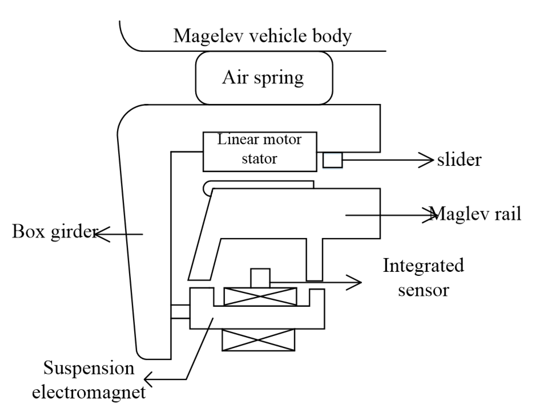
2. Problem Statement

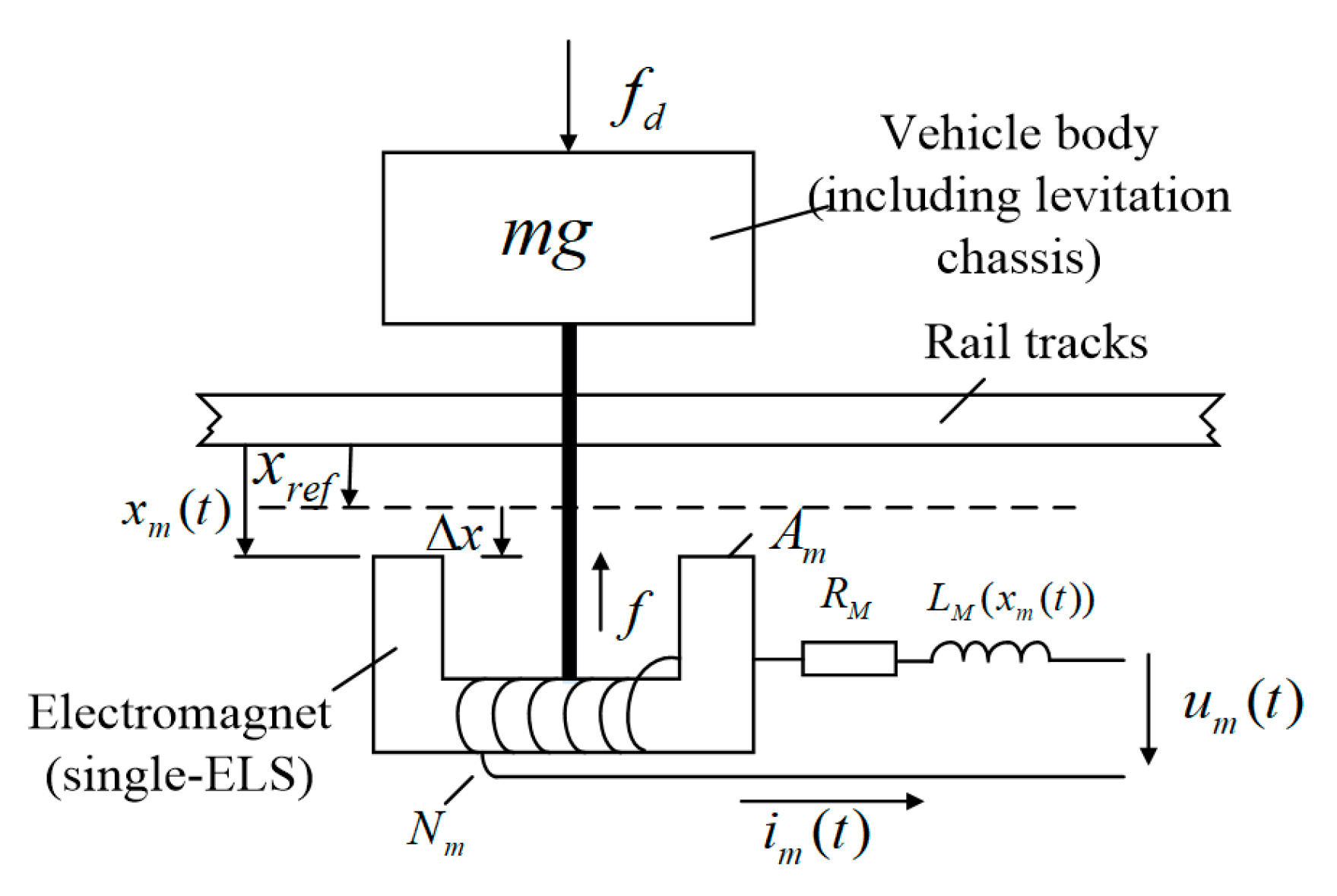
2.1. System Dynamics

The maglev system and single-electromagnet system can be illustrated in Figure 1 and Figure 2. According to Maxwell’s equation and Biot–Savart’s theorem:
F m ( i m ( t ) , x m ( t ) ) = 0 t ψ m ( i m ( t ) , x m ( t ) ) d t x m ( t )
where F m ( i m ( t ) , x m ( t ) ) denotes electromagnetic force; x m ( t ) represents the airgap between the electromagnet and the rail; and i m ( t ) denotes the current.
According to Kirchhoff magnetic-circuit law:
ψ m ( i m ( t ) , x m ( t ) ) = N m N m i m ( t ) R ( x m ) ,
where N m represents the coil number of turns; μ 0 is Air permeability; A m denotes the effective magnetic pole area; and R ( x m ) can be expressed as
R ( x m ) = 2 x m ( t ) μ 0 A m
Substituting Equations (2) and (3) into Equation (1), we can obtain the electromagnetic-force equation of the magnetic-levitation system as:
F m ( i m ( t ) , x m ( t ) ) = μ 0 A m N m 2 4 [ i m ( t ) x m ( t ) ] 2 .
The relationship between voltage and current across the solenoid coil is:
u m ( t ) = i m ( t ) R m + N m ϕ ˙ m ,
where L m is the instantaneous inductance of the electromagnet that can be expressed as:
L m = μ 0 N m 2 A m 2 x m ( t ) ,   ϕ m = L m N m i m ( t ) .
Finishing Equation (6) and deriving its time at both ends:
ϕ ˙ m = μ 0 N m A m 2 x m ( t ) d i m ( t ) d t μ 0 N m A m i m ( t ) 2 x m 2 ( t ) d x m ( t ) d t
By Equations (5) and (7), we can obtain the electrical electromagnet equation:
u m ( t ) = i m ( t ) R m + μ 0 N m 2 A m 2 x m ( t ) d i m ( t ) d t μ 0 N m 2 A m i m ( t ) 2 x m 2 ( t ) d x m ( t ) d t
Assuming f d is the disturbance force applied to the maglev-train system, the model of the magnetic-suspension system can be rewritten as follows:
m x ¨ m ( t ) = μ 0 A m N m 2 4 [ i m ( t ) x m ( t ) ] 2 + m g + f d .
Convert Equations (8) and (9) to state-space expressions. Here, the system state is x 1 ( t ) = x m ( t ) , x 2 ( t ) = x ˙ m ( t ) , and y 3 ( t ) = i m ( t ) , and the state-space expression of the floating system is:
{ x ˙ 1 ( t ) = x 2 ( t ) x ˙ 2 ( t ) = μ 0 A m N m 2 4 m [ x 3 ( t ) x 1 ( t ) ] 2 + g + 1 m f d x ˙ 3 ( t ) = x 2 ( t ) x 3 ( t ) x 1 ( t ) + 2 x 1 ( t ) μ 0 N m 2 A m ( u m ( t ) x 3 ( t ) R m )
Remark 1.
In an actual maglev-train levitation system, choppers are utilized to supply power to the levitation electromagnet by the principle of the current following to adjust the current for the electromagnet. As a consequence, only the current loop was considered while designing the controller. In this way, third-order dynamic equations can be degenerated into second-order nonlinear differential equations, as shown.
{ x ˙ 1 ( t ) = x 2 ( t ) x ˙ 2 ( t ) = μ 0 A m N m 2 4 m [ i m ( t ) x 1 ( t ) ] 2 + g + 1 m f d
Remark 2.
As shown in Equation (4), the relative order between nonlinear electromagnetic force F m ( t ) and current i m ( t ) is zero. [ i m ( t ) x 1 ( t ) ] 2 can be taken as u to design the controller. Since air gap x 1 ( t ) can be measured at any time, it is convenient to calculate control current i m ( t ) according to the following formula, as long as the required F m ( t ) is determined.
i m ( t ) = x 1 2 u κ = x 1 2 F m κ ,
where κ = μ 0 A m N m 2 4 m denotes the electromagnetic-force transmission coefficient.
Remark 3.
In Equation (9), considering problems such as passenger fluctuation and parameter perturbation, the actual dynamic equation of the magnetic-suspension system can be rewritten as follows:
( m + Δ m ) x ¨ m ( t ) = μ 0 A m N m 2 4 u + ( m + Δ m ) g + f d
Lumped uncertainty term is defined as n u = Δ m g Δ m x ¨ m ( t ) + f d , so Equation (13) can be rewritten as follows:
m x ¨ m ( t ) = μ 0 A m N m 2 4 u + m g + n u .
Then, Equation (11) can be rewritten as:
[ x ˙ 1 x ˙ 2 ] = [ 0 1 0 0 ] [ x 1 x 2 ] + [ 0 1 m ] ( μ 0 A m N m 2 4 u + m g + n u )
or
X ˙ = A 1 X + B ( μ 0 A m N m 2 4 u + m g + n u ) ,
where A 1 = [ 0 1 0 0 ] , B = [ 1 1 m ] and X = [ x 1 x 2 ] .
Remark 4.
In the actual system, signal transmission in the maglev control system would be delayed, which may cause serious safety accidents [12,13,14]. In this paper, time delay was introduced into the dynamic modeling. Time delay in states was only considered to facilitate controller design, and time delay in the control signal caused by inductance was not considered. Thus, the magnetic-levitation-system dynamics model shown in Equation (16) can be written as follows:
X ˙ = A 1 X + A 2 X ( t τ ) + B ( μ 0 A m N m 2 4 u + m g + n u ) ,
where τ R + represents time delay in this closed-loop system. A 2 is a known matrix, and A 2 2 × 2 .

2.2. Control Object

The control plant can be described in Equation (17) with a time-delay environment. u is the desired controller, and the desired system states can be denoted by X d .
The control objective is to develop a controller u such that, the maglev system states X of the time-delay system (17) can asymptotically track the desired system states X d facing disturbance and time delay simultaneously. In the next section, the designed control law is proposed to satisfy the above control objective.

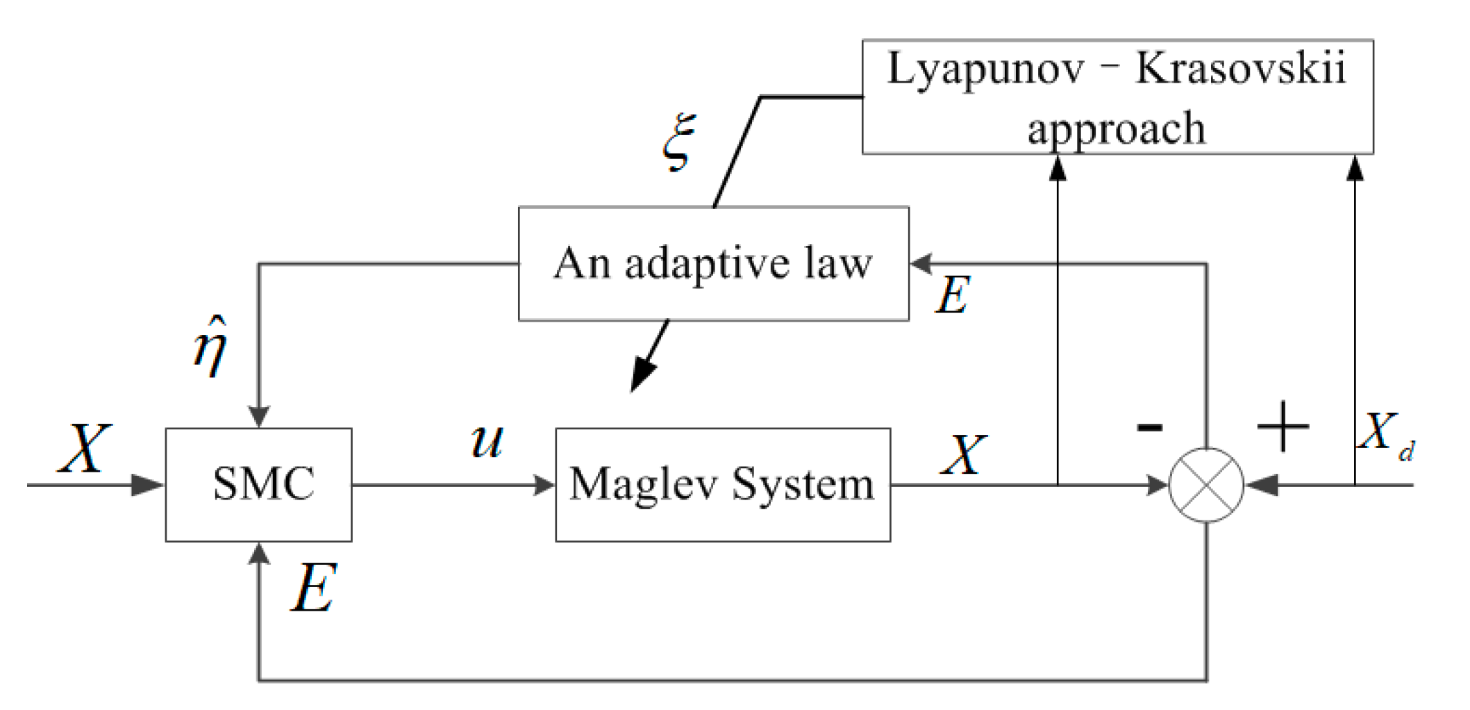
3. Controller Design

To achieve the previous control objectives, the system error vector is defined as E ( t ) 2 × 1 .
E ( t ) = X X d ,
where X d = [ x 1 d 0 ] T and x 1 d are the target air gaps of the maglev vehicle.
Taking the time derivative of Equation (18), we can obtain the following relationship:
E ˙ = X ˙ X ˙ d
The following condition must be met if the system is to be stable at the target air-gap position.
lim t E ( t ) = 0
To facilitate subsequent controller design, actuator saturation is not considered. Taking into account the actual working conditions of a maglev train, the following reasonable assumption is given:
Assumption 1.
There exist matrix P and positive definite matrices Q , J , and K 2 that satisfy the following Riccati equation:
( A 1 B K 2 ) T P + P ( A 1 B K 2 ) + P A 2 J 1 A 2 T P = Q J
On the basis of the desired state in Equation (18) and the system in Equation (17), the ideal response of the system is given by the following reference model:
X ˙ d = ϕ m X d + A 2 X d ( t τ ) + φ m σ ,
where σ 2 × 1 is a bounded reference signal; ϕ m , φ m 2 × 2 and their equations are as follows:
ϕ m = A 1 + B ( K 1 K 2 ) ,   φ m = B K 3 ,
where K 1 , K 2 , and K 3 1 × 2 , and they are optional.
From Equation (23), matrices ϕ m A 1 + B K 2 and φ m are a linear combination of matrix B . If matrix B is linearly independent of matrix φ m , which can avoid redundancy in inputs, matrices K 1 and K 3 are as follows:
K 1 = ( B T B ) 1 B T ( ϕ m A 1 + B K 2 ) = ( φ m T B ) 1 φ m T ( ϕ m A 1 + B K 2 )
K 3 = ( B T B ) 1 B T φ m = ( φ m T B ) 1 φ m T φ m
For the sake of improving system adaptability and robustness, an adaptive sliding-mode controller is proposed as follows:
u = 4 μ 0 A m N m 2 [ K 2 X K 1 X d K 3 σ + η ^ sgn ( B T P E ) ] ,
where sgn ( · ) is the signum functional; η ^ is the adjustable estimate of η and it was designed as follows:
η ^ ˙ = ξ | | E T P B | | ,
where ξ is the adaptive factor and ξ R + , which was used to adjust the estimated speed of η ^ .
Choosing suitable adaptive gain can effectively reduce the chattering phenomenon and remove the requirement of knowing the bound of uncertainties.

4. Closed-Loop Stability Analysis

Theorem 1.
There exist matrices X and X n × n , any positive constant a , symmetric positive definite matrix Y , and x 1 , x 2 n ; so, we have:
2 x 1 T X x 2 a x 1 T X Y 1 X T x 1 + 1 a x 2 T Y x 2
Proof. 
For any constant a > 0 and any symmetric matrix Y > 0 ,
0 a [ X T x 1 1 a Y x 2 ] T Y 1 [ X T x 1 1 a Y x 2 ] = a x 1 T X Y 1 X T x 1 2 x 1 T X x 2 + 1 a x 2 T Y x 2 .
In combination with Equations (17), (22), and (23), the first-order derivative of the error is:
E ˙ = X ˙ X ˙ d = A 1 X + A 2 X ( t τ ) + B ( μ 0 A m N m 2 4 u + m g + n u ) ϕ m X d A 2 X d ( t τ ) φ m σ = A 1 E + A 2 E ( t τ ) B K 3 σ B K 1 X d + B K 2 X d + B ( μ 0 A m N m 2 4 u + m g + n u )
Equation (26) can be rewritten with controller (24) as follows:
E ˙ = ( A 1 B K 2 ) E + A 2 E ( t τ ) B [ η ^ sgn ( B T P E ) m g n u ]
Theorem 2.
The proposed adaptive levitation control law (24) with adaptive law (25) can guarantee that η ^ has an upper bound and can also drive error vector E ( t ) to be zero within a finite time.
Proof. 
The Lyapunov–Krasovskii function was selected as:
V = 1 2 E T P E + 1 2 t t τ E T ( δ ) J E ( δ ) d δ + 1 2 ξ η ˜ 2 ,
where η ˜ = η η ^ and ξ is a positive constant. The derivative of Equation (28) with respect to time yields can be obtained as follows:
V ˙ = 1 2 E ˙ T P E + 1 2 E T P E ˙ + 1 2 E T J E 1 2 E T ( t τ ) J E ( t τ ) 1 ξ η ˜ η ^ ˙ .
Substitute error Equation (27) into Equation (29) and obtain the following:
V ˙ = 1 2 E T J E 1 2 E T ( t τ ) J E ( t τ ) 1 ξ η ˜ η ^ ˙ η ^ | | E T P B | | + E T P B ( m g + n u ) + E T P A 2 E ( t τ ) + 1 2 E T [ P ( A 1 B K 2 ) + ( A 1 B K 2 ) T P ]
Then, utilize Theorem 1 and obtain the following:
E T P A 2 E ( t τ ) 1 2 E T ( t τ ) J E ( t τ ) + 1 2 E T P A 2 J 1 A 2 T P E .
By combining Equations (30) and (31), the following can be obtained:
V ˙ 1 2 E T [ P ( A 1 B K 2 ) + ( A 1 B K 2 ) T P + J + P A 2 J 1 A 2 T P ] 1 ξ η ˜ η ^ ˙ η ^ | | E T P B | | + E T P B ( m g + n u ) 1 2 E T Q E 1 ξ η ˜ η ^ ˙ η ^ | | E T P B | | + E T P B ( m g + n u ) 1 2 E T Q E 1 ξ η ˜ η ^ ˙ η ^ | | E T P B | | + | | E T P B | | | | m g + n u | |
On the basis of Theorem 1, Equation (32) can be rewritten as follows:
V ˙ 1 2 E T Q E + η ¯ ( | | E T P B | | 1 ξ η ^ ˙ )
Equation (34) can be elicited by incorporation with Equations (33) and (25).
V ˙ 1 2 E T Q E ,
since Q is a positive definite matrix in the Riccati equation. V ˙ is negative semidefinite, and V ( η ˜ ( t ) ) V ( η ˜ ( 0 ) ) , which proves that η ^ is bounded. That is, there exists a constant η d R + that satisfies t > 0 , η ^ ( t ) η d .
Define Ψ ( t ) = 1 2 E T Q E V ˙ and integrate it with respect to time yields. Then, we can obtain the following:
0 t Ψ ( τ ) d τ V ( η ˜ ( 0 ) ) V ( η ˜ ( t ) )
The result can be obtained because V ( η ˜ ( 0 ) ) is bounded and V ( η ˜ ( t ) ) is not ever-increasing and bounded.
lim t 0 t Ψ ( τ ) d τ
Ψ ( t ) is also bounded, so it can be proven that lim t Ψ ( t ) = 0 by utilizing Barbalat’s lemma [19,20,21]. Therefore, lim t E = 0 . QED.
In summary, the control architecture of the proposed controller can be described in Figure 3.

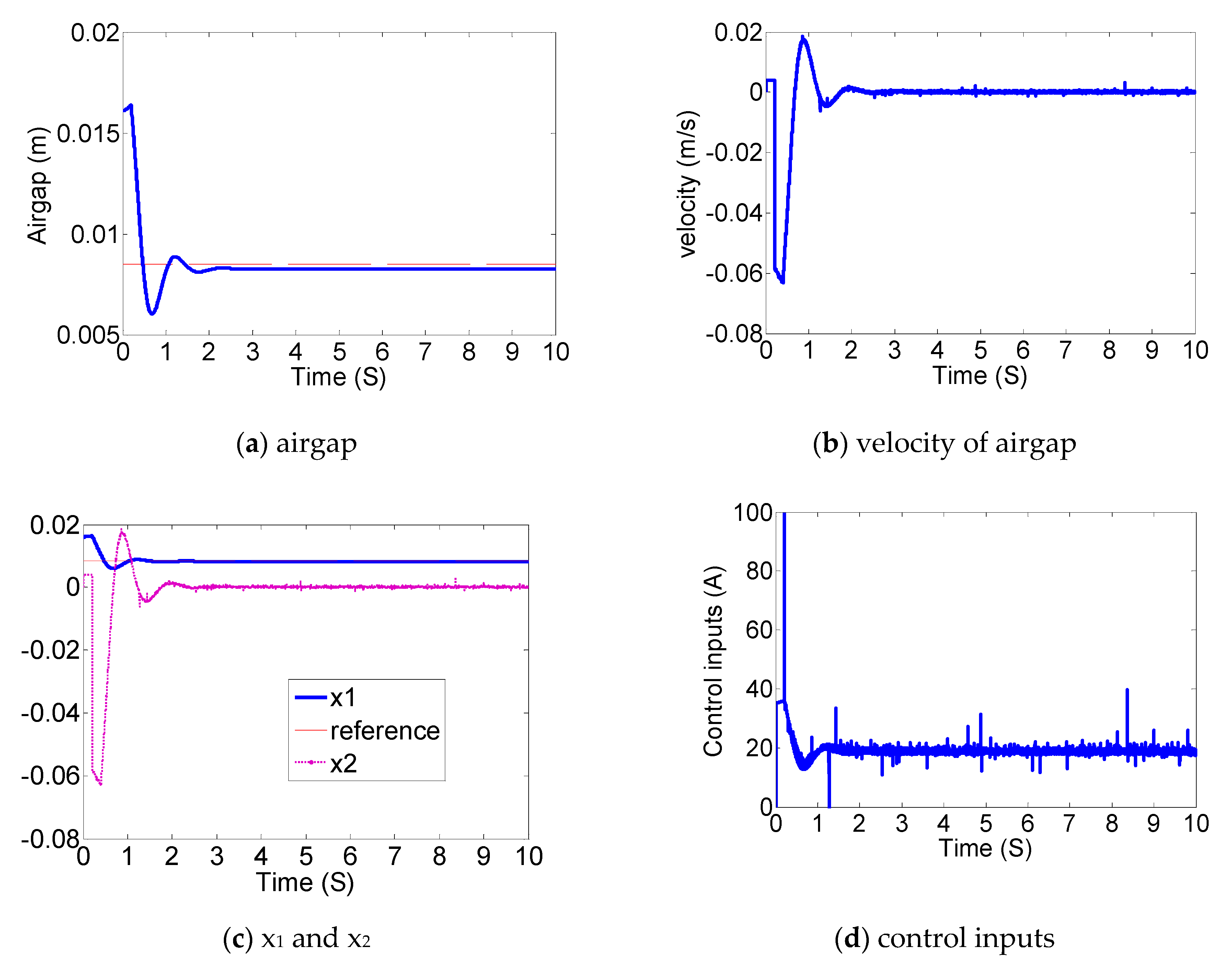
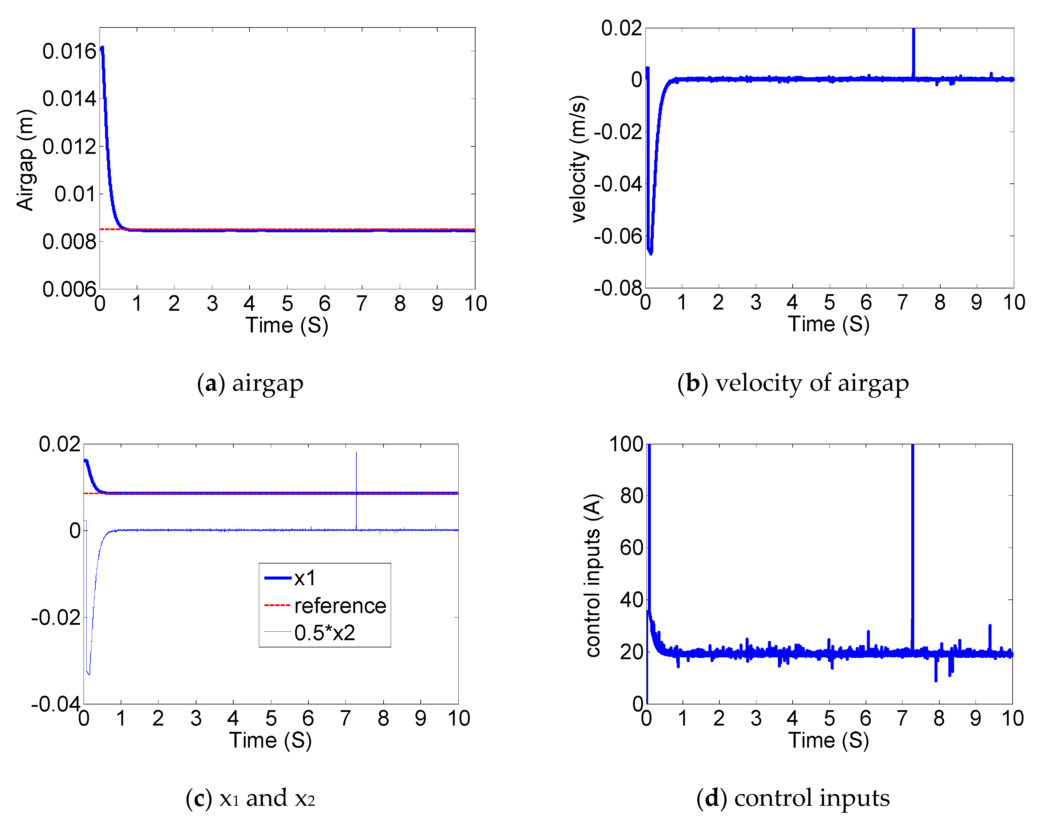
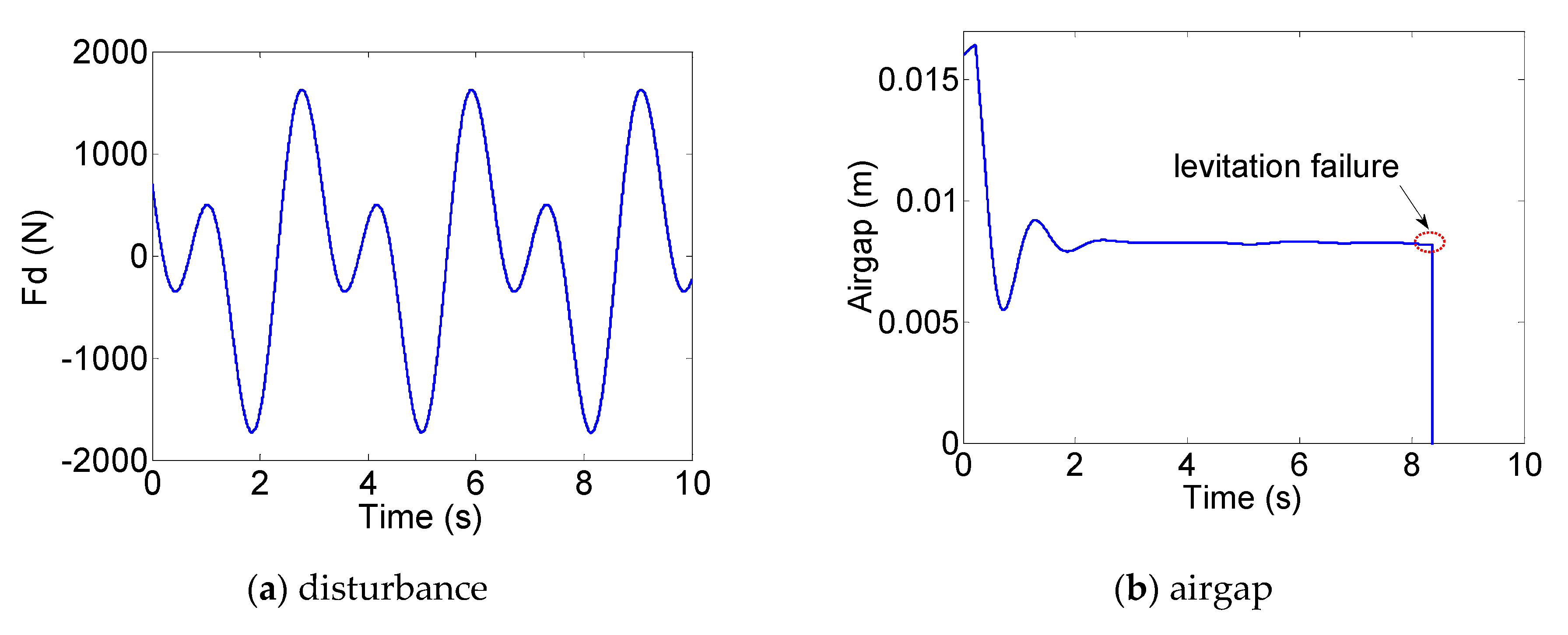
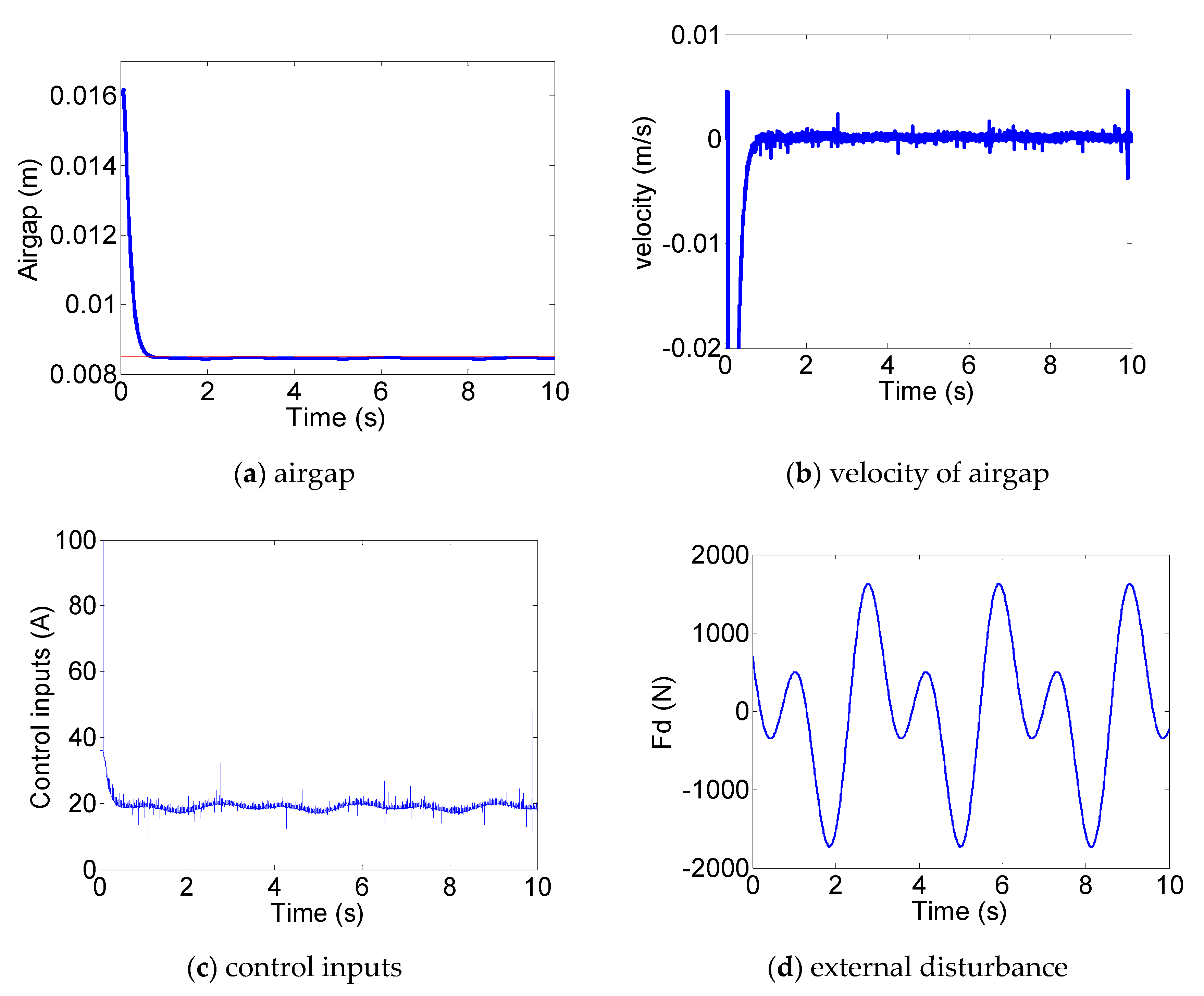
5. Simulation Results

In order to demonstrate the superiority of the proposed adaptive robust controller while coping with an uncertain time delay for a maglev-train system, the conventional PID (proportion integration differentiation) controller, the traditional sliding mode controller (SMC) [22,23,24,25,26,27,28], and the proposed controller were respectively applied to the maglev system in the simulation model. MATLAB/Simulink was utilized to provide the simulation environment. The values of the system parameters are outlined in Table 1.
Without loss of generality, the values of n u and A 2 were selected as below:
n u = e 0.5 t sin ( t )
A 2 = d i a g ( [ 0.03 randi ( 10 ) 0.001 randi ( 20 ) ] )
For the proposed controller in this paper, gains were chosen as: K 1 = 0 , K 2 = [ 35.4 8.12 ] , K 2 = [ 0.065 0.0971 ] , and ξ = 66.72 . The reference signal was selected as: σ = [ 0.6 0 ] T . The initial state of the system was X 0 = [ 0.0016 0 ] T . The control target trajectory was X d = [ 0.0085 0 ] T . The traditional PID controller is selected, and the control parameters are k p = 1800 , k i = 150 , and k d = 1150 based on the Root Locus method. The parameters of the SMC controller are chosen as: c 1 = 20 , c 2 = 5 , k smc = 15 , ξ smc = 20 .
The performance of the proposed controller, the SMC controller, and the PID controller were simulated under the two following cases. Case 1: Levitation without disturbance. Case 2: Levitation with disturbance.
(1) Levitation without disturbance and with uncertain time delay. The Matlab/SimEvent® is utilized to build the CAN model to represent the signal transmission, which CAN reflect the bus load rate and the uncertain time delay.
(2) Levitation with disturbance under uncertain time delay.
The simulation results for the PID controller without disturbance (air-gap response, air-gap changing velocity, and control current) are illustrated in Figure 4. The control current has fluctuations in Figure 4, which is related to the excessive gain. However, a small gain will cause the system to be unstable. The essential reason is that the maglev system is a highly nonlinear system, and the PID is a controller based on linearization theory, which is easy to fail when applied to a nonlinear maglev system. The simulation results for the SMC controller without disturbance are included in Figure 5 and Figure 6 depicts the simulation results for the proposed adaptive robust levitation controller without disturbance. Figure 4, Figure 5 and Figure 6 show that the performance of the PID controller deteriorated with 29.4% overshoot, 0.248 mm steady-state error, and 2.1 s settling time and the SMC controller with 0.248 mm steady-state error and 1.05 s settling time. The performance of the proposed adaptive robust levitation controller was excellent without overshoot and steady-state error.
The simulation results for the PID controller with external disturbances (the air-gap response, the air-gap changing velocity, and the control current) are shown in Figure 7. The simulation results for the SMC controller with disturbances are included in Figure 8 and Figure 9 and depict the simulation results for the proposed adaptive levitation controller with external disturbances. Figure 7 shows that levitation failure appeared with the PID controller. The air gap of the system with the SMC controller in Figure 8 fluctuated above 3.5% and the current response had chattering phenomenon. The proposed adaptive levitation controller could still effectively levitate the train. After stabilization, the air gap of the system fluctuated within 1%. The control performance indexes can be summarized in Table 2 as below.
The simulation results demonstrated the effectiveness of the presented robust levitation controller to deal with uncertain time delay and external disturbances while staying asymptotically stable.

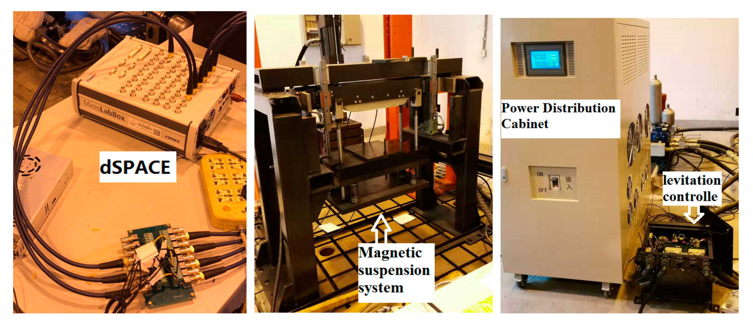
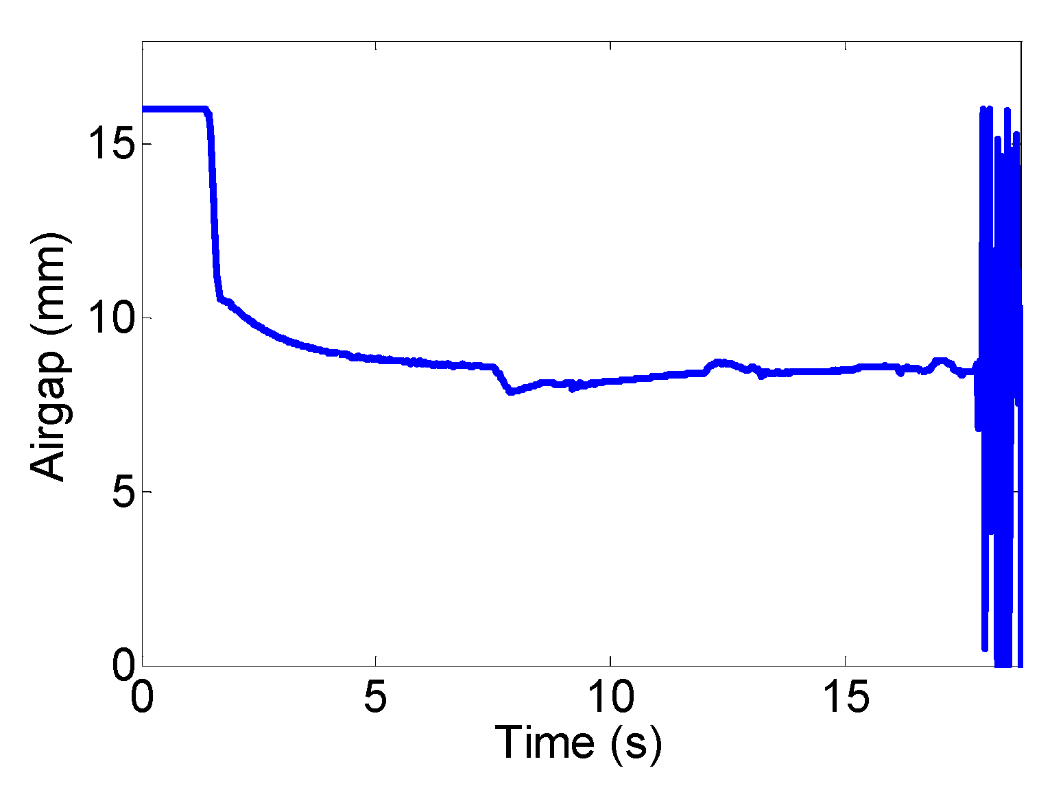
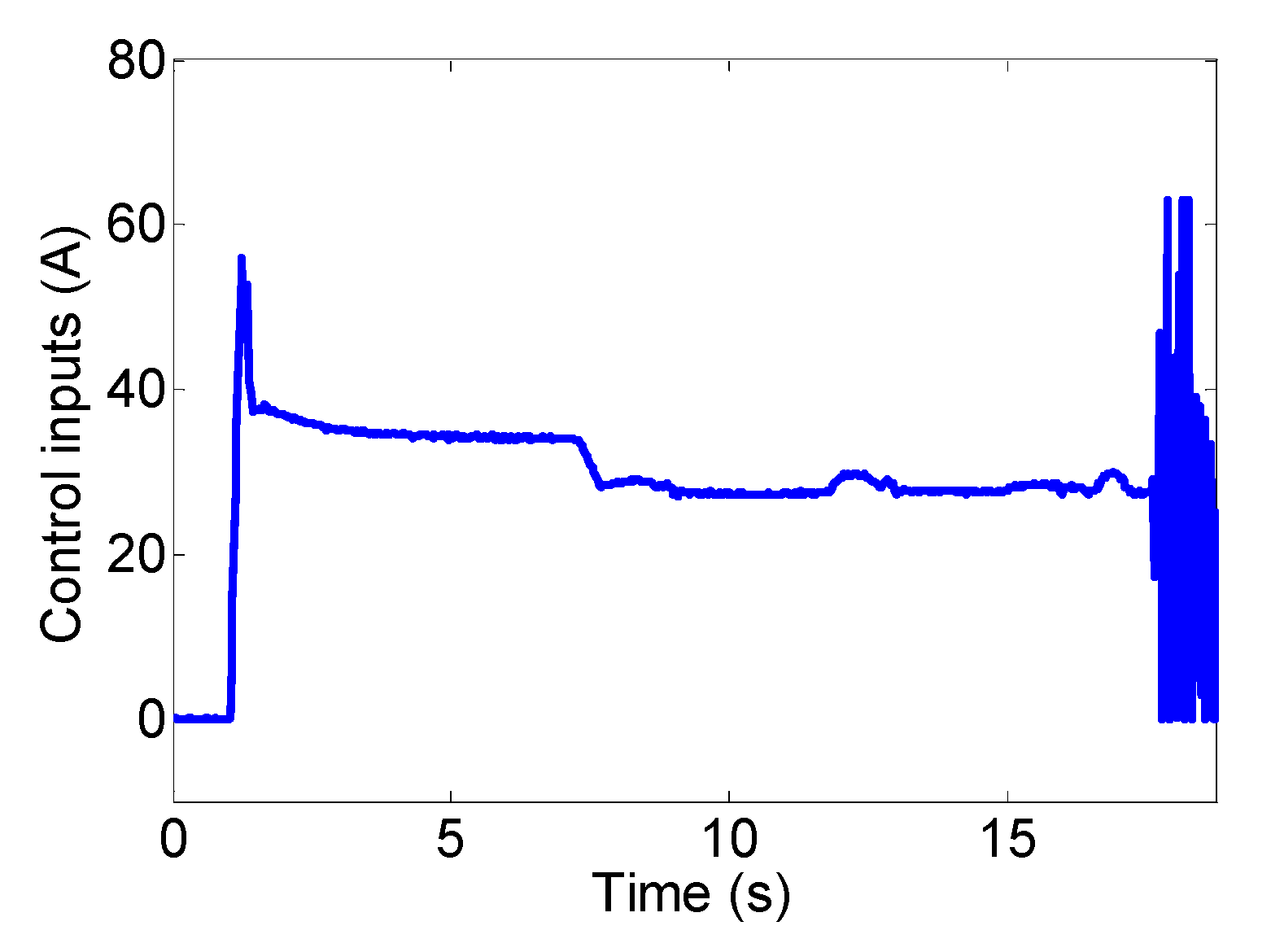
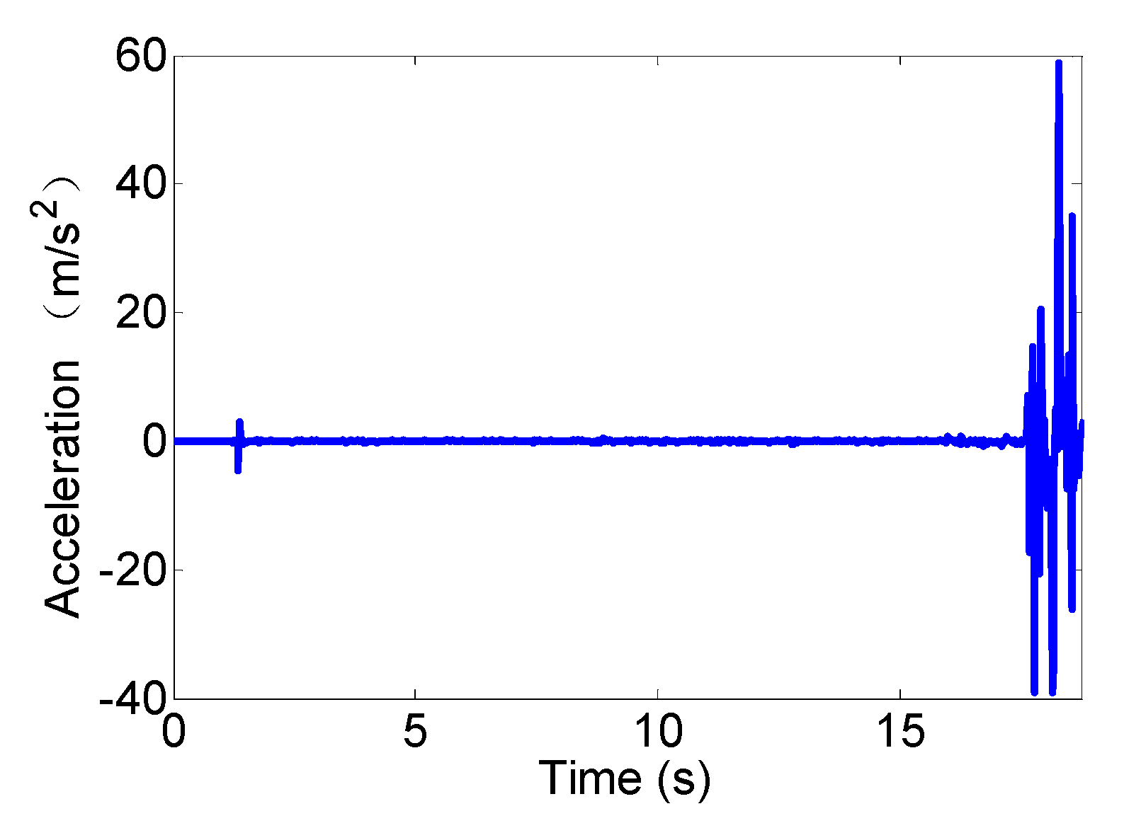
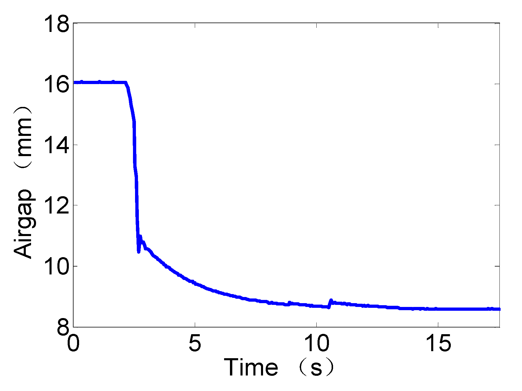
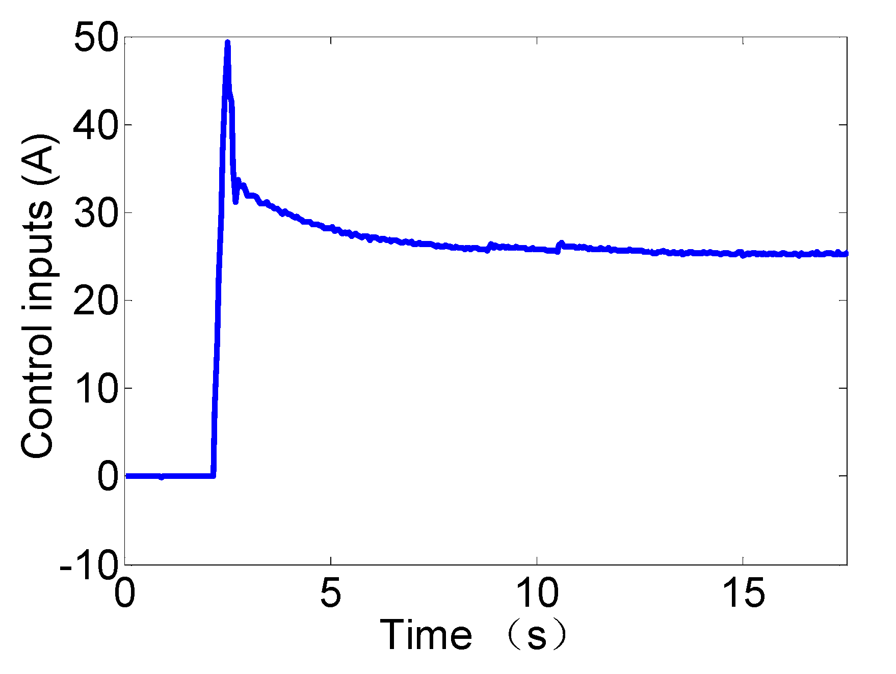
6. Hardware Experiments

After sufficient numerical simulation, hardware experiments were implemented to examine the performance of the presented adaptive levitation controller on a single magnetic-suspension system, which is illustrated in Figure 10. The basic working principle of a single magnetic-suspension system is described in Figure 2. The test bed was composed of dSPACE®, a levitation controller, a power-distribution cabinet, an eddy-current sensor, and a magnetic-suspension system. In particular, the MATLAB/Simulink® Real-Time Windows Target (RTWT) was utilized to set up the proposed control strategy in the loop-system hardware.
Experiment results of the PID levitation controller with an uncertain time delay are provided in Figure 11, Figure 12 and Figure 13. We can learn from the Figure 10 that the system becomes unstable after 14 s, at which point the instability causing the rail and electromagnetic is hitting repeatedly.
The experiment results of the proposed robust levitation controller (RLC) with an uncertain time delay are provided in Figure 14, Figure 15 and Figure 16.
In summary, Figure 14, Figure 15 and Figure 16 show that the air gap of the magnetic suspension system was stable, and the time-delay influence could be significantly reduced with the proposed robust levitation controller.

7. Conclusions

In this paper, a novel adaptive robust levitation control approach was developed to deal with uncertain time delays and external disturbances. The mathematical model of the magnetic-suspension systems was constructed. The proposed adaptive levitation controller could improve robustness against time delay and uncertainty by utilizing the Riccati method and sliding-mode technology. The proposed adaptive update law could also eliminate the chattering phenomenon without knowing the bound of uncertainty or disturbance in practice. The verification of the theoretical derivations was supported by rigorous Lyapunov-based analysis. The simulation results were provided to show the superiority of the proposed controller over the conventional control method when facing uncertain time delays and external disturbances. Hardware experiment results were included to show that the proposed robust levitation controller achieved satisfactory control performance against uncertain time delays. In future work, we will focus on the time delay problem for maglev vehicle—guideway interaction systems—which considers guideway elasticity by utilizing the robust levitation control strategy.

Author Contributions

Y.-g.S. designed the controller and drafted the paper. S.X. performed the simulations. J.-q.X. and G.-b.L. help stability analysis and carried out the experiments. All authors have read and agreed to the published version of the manuscript.

Funding

This work was supported by the National Natural Science Foundation of China under Grant 51905380, by China Postdoctoral Science Foundation under Grant 2019M651582, by National Key R&D Program of China under Grant 2016YFB1200600 and National Key Technology R&D Program of the 13th Five-year Plan, (2016YFB1200602).

Acknowledgments

The authors would like to acknowledge H. Y Qiang and S. H. Wang from Shanghai Maritime University for technical support in this study.

Conflicts of Interest

The authors declare no conflict of interest.

References

  1. Thornton, R.D. Efficient and Affordable Maglev Opportunities in the United States. Proc. IEEE 2009, 97, 1901–1921. [Google Scholar] [CrossRef]
  2. Murai, M. Maglev Train HSST is Now on Commercial Operation as LINIMO. J. Jpn. Soc. Mech. Eng. 2008, 111, 472–473. [Google Scholar]
  3. Ohtani, S.; Hosokawa, O.; Siraki, A. Design of the Linimo Maglev Train. IATSS Rev. 2007, 32, 14–20. [Google Scholar]
  4. Luguang, Y. The maglev development and commercial application in China. In Proceedings of the 2007 International Conference on Electrical Machines and Systems, Seoul, Korea, 8–11 October 2007; pp. 1942–1949. [Google Scholar]
  5. Luguang, Y. Progress of the maglev transportation in China. IEEE Trans. Appl. Supercond. ASC 2006, 16, 1138. [Google Scholar] [CrossRef]
  6. Yau, J. Vibration control of maglev vehicles traveling over a flexible guideway. J. Sound Vib. 2009, 321, 184–200. [Google Scholar] [CrossRef]
  7. Sun, Y.; Xu, J.; Qiang, H.; Lin, G. Adaptive neural-fuzzy robust position control scheme for maglev train systems with experimental verification. IEEE Trans. Ind. Electron. 2019, 66, 8589–8599. [Google Scholar] [CrossRef]
  8. He, G.; Li, J.; Cui, P. Nonlinear control scheme for the levitation module of maglev train. J. Dyn. Syst. Meas. Control Trans. ASME 2016, 138, 1–8. [Google Scholar] [CrossRef]
  9. Li, J.; Li, J.; Zhou, D.; Cui, P.; Wang, L.; Yu, P. The active control of maglev stationary self-excited vibration with a virtual energy harvester. IEEE Trans. Ind. Electron. 2015, 62, 2942–2951. [Google Scholar] [CrossRef]
  10. Zhou, D.; Yu, P.; Wang, L.; Li, J. An adaptive vibration control method to suppress the vibration of the maglev train caused by track irregularities. J. Sound Vib. 2017, 408, 331–350. [Google Scholar] [CrossRef]
  11. MacLeod, C.; Goodall, R.M. Frequency shaping LQ control of maglev suspension systems for optimal performance with deterministic and stochastic inputs. IEE Proc. Control. Theory Appl. 1996, 143, 25–30. [Google Scholar] [CrossRef]
  12. Xu, J.; Du, Y.; Chen, Y.H.; Guo, H. Adaptive robust constrained state control for non-linear maglev vehicle with guaranteed bounded airgap. IET Control Theory Appl. 2018, 12, 1573–1583. [Google Scholar] [CrossRef]
  13. Wang, H.; Zhong, X.; Shen, G. Analysis and experimental study on the MAGLEV vehicle-guideway interaction based on the full-state feedback theory. J. Vib. Control 2015, 21, 408–416. [Google Scholar] [CrossRef]
  14. Zhang, L.; Huang, J.; Huang, L.; Zhang, Z. Stability and bifurcation analysis in a maglev system with multiple delays. Int. J. Bifurc. Chaos 2015, 25, 1550074. [Google Scholar] [CrossRef]
  15. Zhang, L.; Huang, L.; Zhang, Z. Stability and Hopf bifurcation of the maglev system with delayed position and speed feedback control. Nonlinear Dynam. 2009, 57, 197–207. [Google Scholar] [CrossRef]
  16. Hong-Po, W.; Jie, L.I.; Zhang, K. Stability and Hopf bifurcation of the maglev system with delayed speed feedback control. Acta Autom. Sin. 2007, 33, 829–834. [Google Scholar]
  17. Zhang, L.; Campbell, S.A.; Huang, L. Nonlinear analysis of a maglev system with time-delayed feedback control. Physica D 2011, 240, 1761–1770. [Google Scholar] [CrossRef] [Green Version]
  18. Xu, J.; Chen, C.; Gao, D.; Luo, S.; Qian, Q. Nonlinear dynamic analysis on maglev train system with flexible guideway and double time-delay feedback control. J. Vibroeng. 2017, 19, 6346–6362. [Google Scholar]
  19. Sun, N.; Liang, D.; Wu, M.; Chen, Y.; Qin, Y.; Fang, Y. Adaptive control for pneumatic artificial muscle systems with parametric uncertainties and unidirectional input constraints. IEEE Trans. Ind. Electron. 2019. [Google Scholar] [CrossRef]
  20. Wu, Z.; Xia, Y.; Xie, X. Stochastic Barbalat’s lemma and its applications. IEEE Trans. Autom. Control. 2011, 57, 1537–1543. [Google Scholar] [CrossRef]
  21. Yang, T.; Sun, N.; Chen, H.; Fang, Y. Neural network-based adaptive antiswing control of an underactuated ship-mounted crane with roll motions and input dead zones. IEEE Trans. Neural Netw. Learn. Syst. 2019. [Google Scholar] [CrossRef]
  22. Sun, Y.; Li, W.; Lin, G.; Xu, J. Dynamic Modeling and Nonlinear Control Research on Magnetic Suspension Systems of Low-speed Maglev Train. Tongji Daxue Xuebao J. Tongji Univ. 2017, 45, 741–749. [Google Scholar]
  23. Zhang, M.; Zhang, Y.; Ouyang, H.; Ma, C.; Cheng, X. Adaptive integral sliding mode control with payload sway reduction for 4-DOF tower crane systems. Nonlinear Dyn. 2020, in press. [Google Scholar] [CrossRef]
  24. Shengquan, L.; Juan, L.; Yongwei, T.; Yanqiu, S.; Wei, C. Model-based model predictive control for a direct-driven permanent magnet synchronous generator with internal and external disturbances. Trans. Inst. Meas. Control 2020, 42, 586–597. [Google Scholar] [CrossRef]
  25. Chen, H.; Sun, N. Nonlinear control of underactuated systems subject to both actuated and unactuated state constraints with experimental verification. IEEE Trans. Ind. Electron. 2019, in press. [Google Scholar] [CrossRef]
  26. Sun, N.; Fu, Y.; Yang, T.; Zhang, J.; Fang, Y.; Xin, X. Nonlinear motion control of complicated dual rotary crane systems without velocity feedback: Design, analysis, and hardware experiments. IEEE Trans. Autom. Sci. Eng. 2020, in press. [Google Scholar] [CrossRef]
  27. Chen, H.; Xuan, B.; Yang, P.; Chen, H. A new overhead crane emergency braking method with theoretical analysis and experimental verification. Nonlinear Dyn. 2019, 98, 2211–2225. [Google Scholar] [CrossRef]
  28. Zhang, M.; Zhang, Y.; Ji, B.; Ma, C.; Cheng, X. Modeling and energy-based sway reduction control for tower crane systems with double-pendulum and spherical-pendulum effects. Meas. Control 2019, in press. [Google Scholar] [CrossRef] [Green Version]
Figure 1. Structure of maglev system.
Applsci 10 01179 g001
Figure 2. Single-electromagnet system.
Applsci 10 01179 g002
Figure 3. Control architecture of the proposed robust levitation controller.
Applsci 10 01179 g003
Figure 4. Simulation results for the PID controller without disturbance (dashed line: the reference airgap).
Applsci 10 01179 g004
Figure 5. Simulation results for the sliding mode controller (SMC) without disturbance (dashed line: the reference airgap).
Applsci 10 01179 g005
Figure 6. Simulation results for the proposed robust levitation controller without disturbance (red dashed line: the reference airgap).
Applsci 10 01179 g006
Figure 7. Simulation results for the PID controller with external disturbance. (a) Nonlinear external disturbance. (b) Airgap response.
Applsci 10 01179 g007
Figure 8. Simulation results for the PID controller with external disturbance.
Applsci 10 01179 g008
Figure 9. Simulation results for the proposed robust levitation controller with external disturbance.
Applsci 10 01179 g009
Figure 10. The experimental platform of the magnetic suspension system with dSPACE.
Applsci 10 01179 g010
Figure 11. Experiment results with PID: airgap.
Applsci 10 01179 g011
Figure 12. Experiment results with PID: current.
Applsci 10 01179 g012
Figure 13. Experiment results with PID: electromagnetic acceleration.
Applsci 10 01179 g013
Figure 14. Experiment results with the robust levitation controller (RLC): airgap.
Applsci 10 01179 g014
Figure 15. Experiment results with RLC: current.
Applsci 10 01179 g015
Figure 16. Experiment results with RLC: electromagnetic acceleration.
Applsci 10 01179 g016
Table 1. Parameter values for the magnetic-suspension system.
Physical QuantityValue
Levitation mass ( k g )100
Coil resistance ( Ω )0.420
Coil inductance ( m H )177.8
Number of coil turns N m 340
Magnetic-pole width ( m m )28
Magnetic-pole length ( m m )700
Air permeability μ 0 / ( H m 1 ) 4 π × 10 7
Target levitation air gap ( m m )8.5
Table 2. Summary of numerical values.
Experiment (Time Delay)PIDSMCProposed Method
Case 1: normalTime2.10 s1.05 s0.82 s
Error0.248 mm0.07 mm<0.01 mm
overshoot29.4%00
ChatteringNoneyesNone
Case 2: disturbanceTime2.18 s1.12 s0.91 s
Max ErrorUnstable0.3 mm<0.1 mm
Air-gap fluctuationUnstable>3.5%<1%
Chattering/yesnone

