Design of a Multi-Band Microstrip Textile Patch Antenna for LTE and 5G Services with the CRO-SL Ensemble

 , and
, and 
Abstract
Featured Application
Abstract
1. Introduction
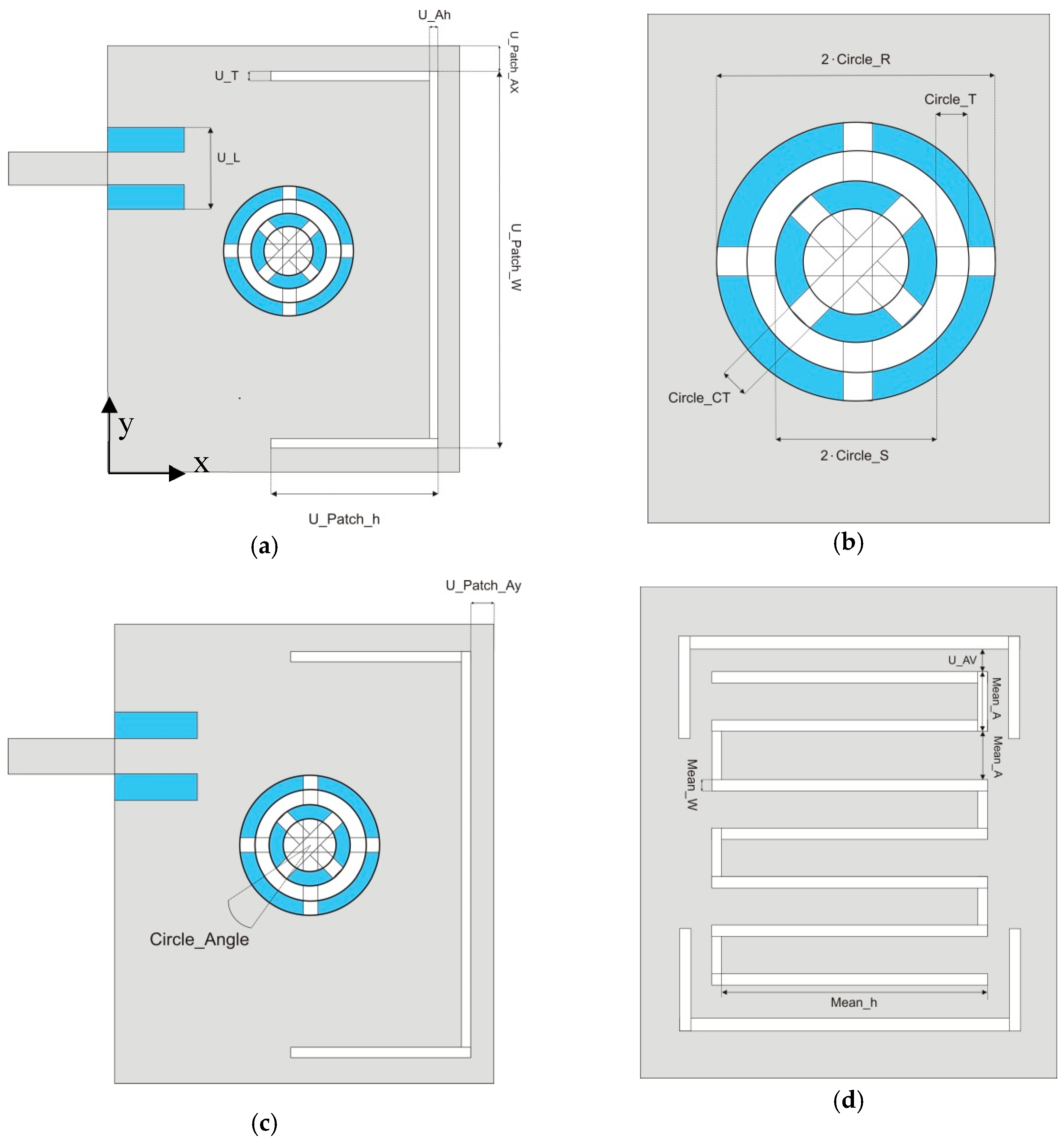
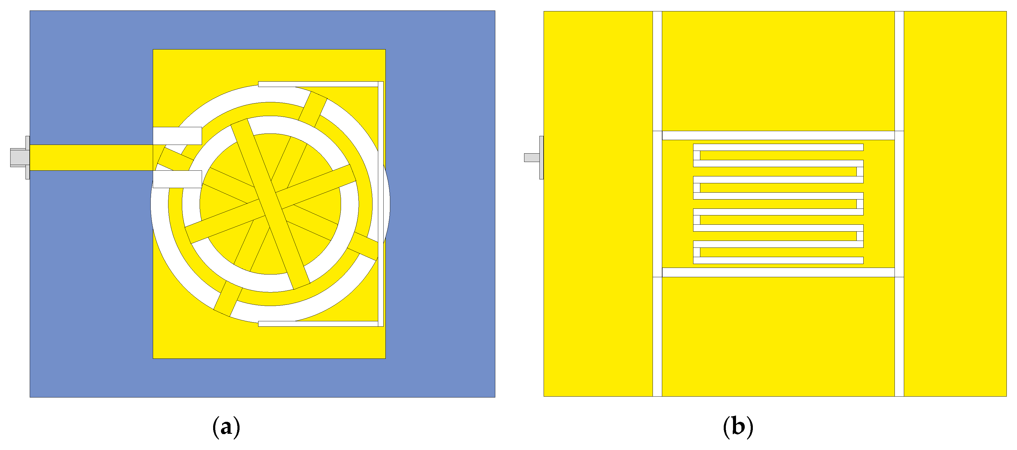
2. Antenna Model
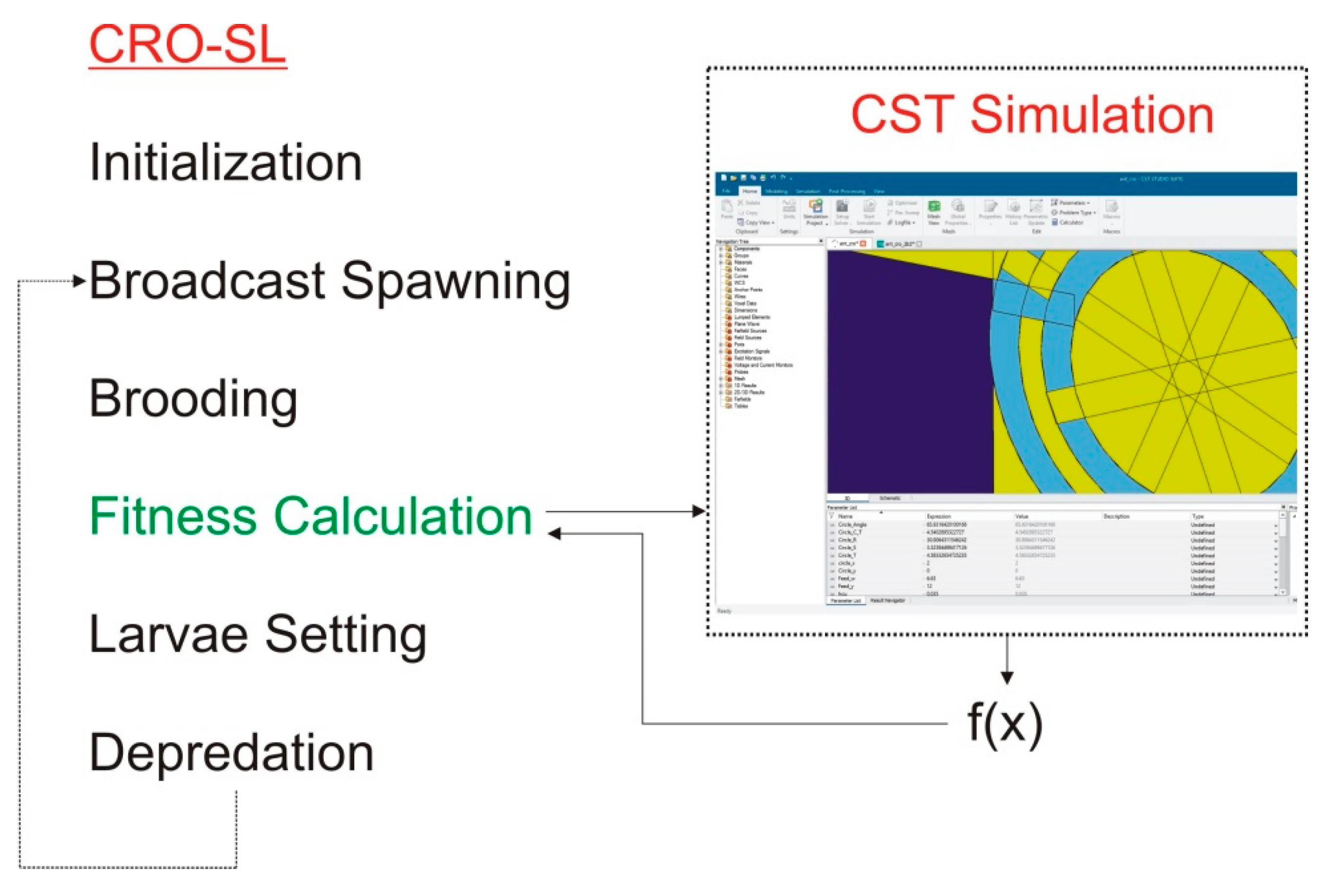
3. Antenna Optimization: the CRO-SL Algorithm
3.1. Substrate Layers Implemented
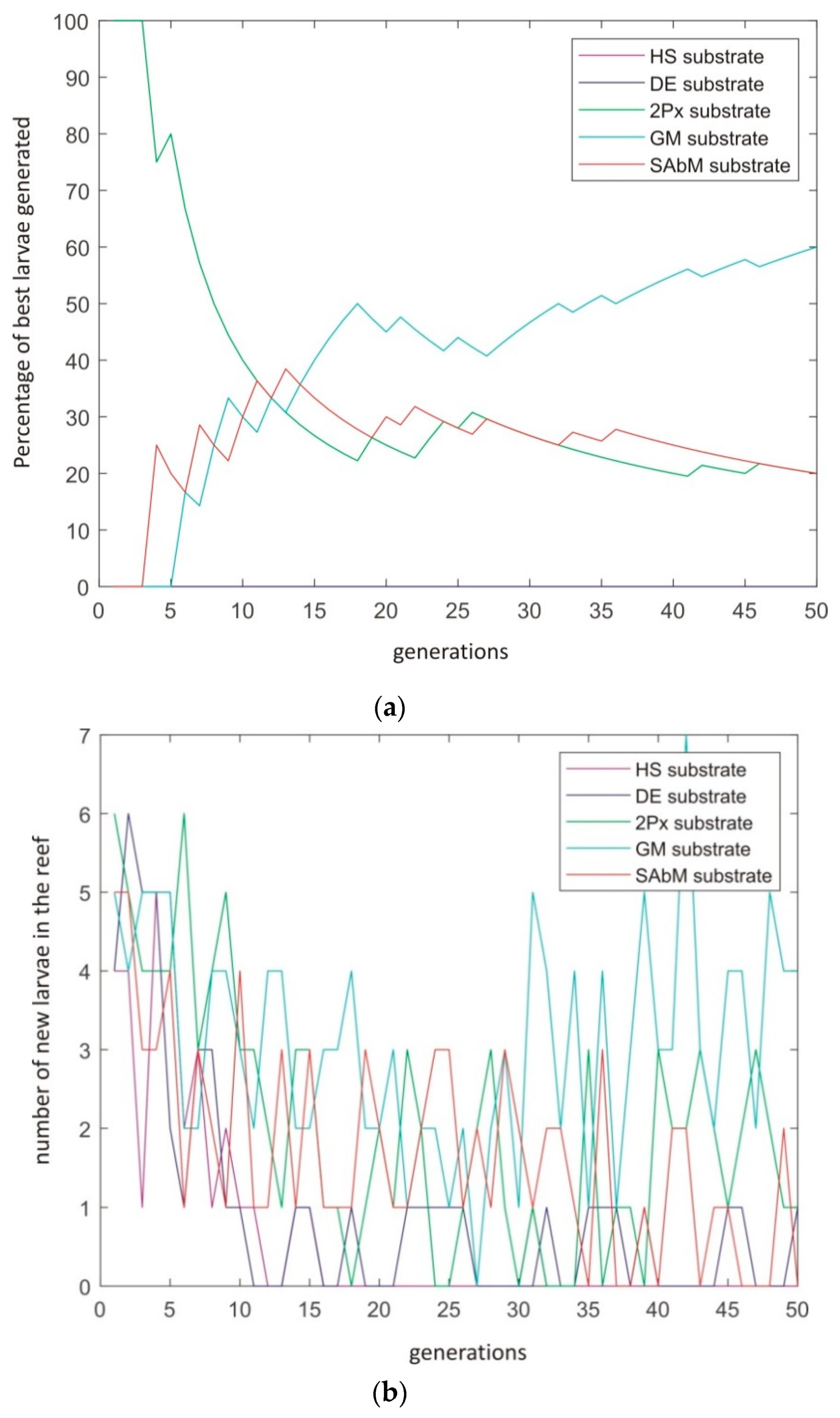
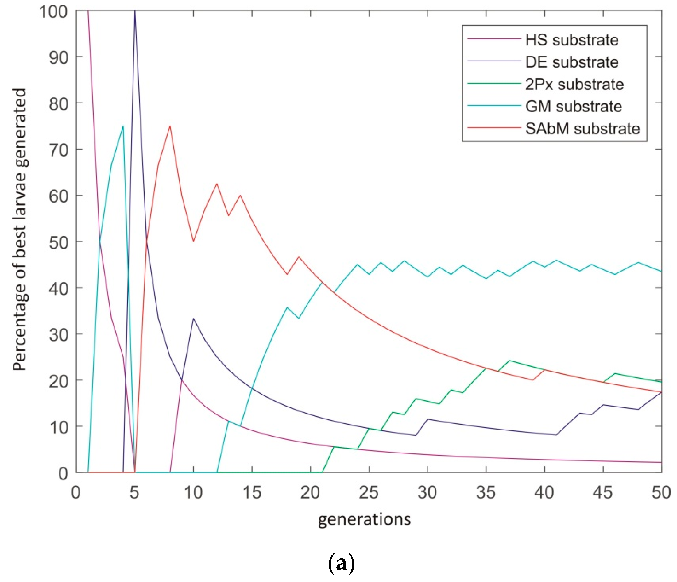
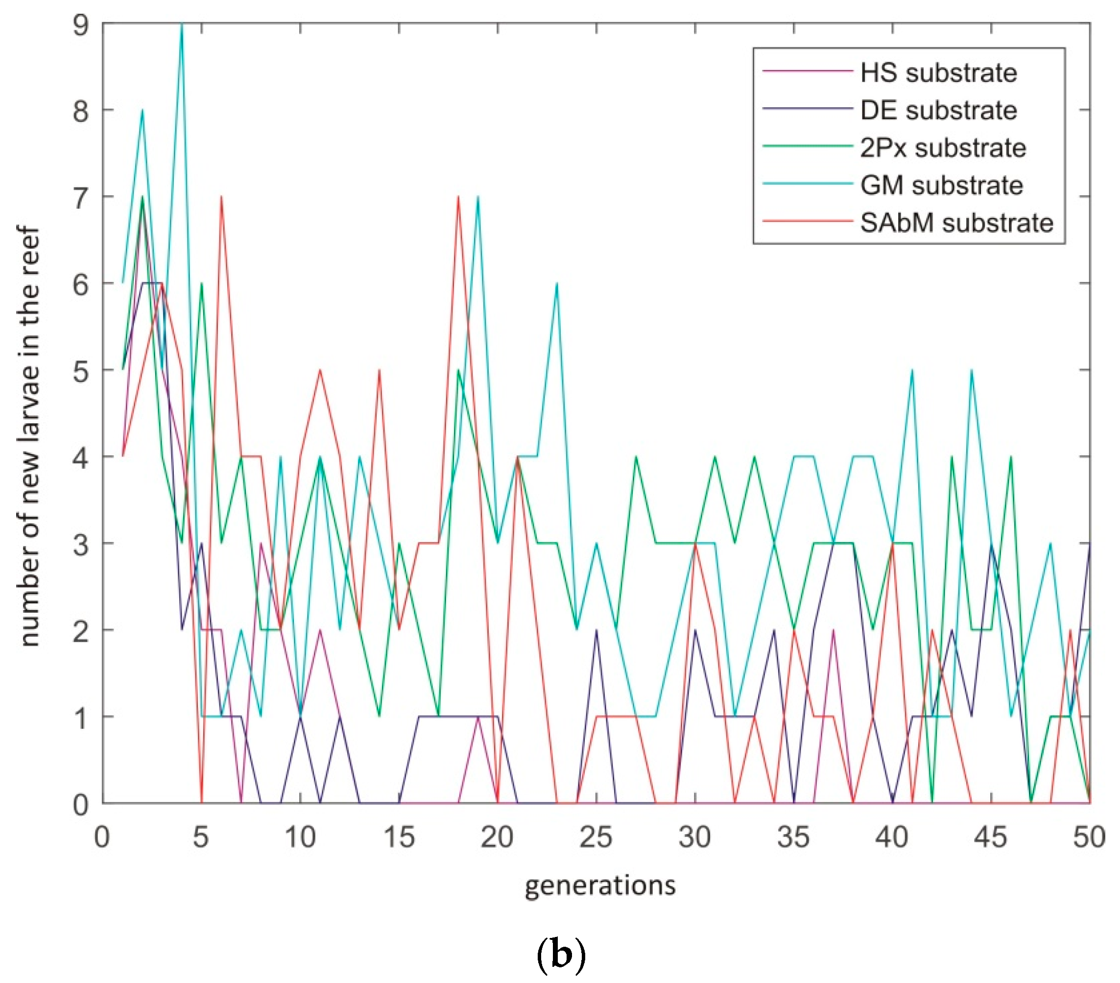
- HS: Mutation using the Harmony Search procedure. Harmony Search [28] is a well-known meta-heuristic based on the how a music orchestra improvises a melody. HS substrate controls the generation of new larvae in one of the following ways: (i) with a probability HMCR in (0, 1) (Harmony Memory Considering Rate), the value of a component of the new solution is drawn uniformly from the same values of the component in other corals of the current reef; and (ii) with a probability PAR in (0, 1) (Pitch Adjusting Rate), where small adjustments are applied to the values of the current solution.
- DE: Differential Evolution algorithm mutation. This substrate is based on the DE algorithm defined in reference [29]. This approach introduces a differential mechanism for exploring the search space. In this case, new larvae are generated by perturbing the current larva by using a vector of differences between two individuals in the population. This perturbation is defined as x′i = x1i + F(x2i − x3i) (where F stands for a weighting the perturbation amplitude, 0.6 in this case). After this perturbation of the current larva, the perturbed vector x′ is in turn combined with an alternative (different) coral in the reef, by means of a classical 2-points crossover, as defined next.
- 2Px: Classical two-points crossover. The crossover operator is the most used operator for exploring the search space in evolutionary computation algorithms [30]. It consists of coupling two individuals at random, and then, after choosing two points for the crossover, interchanging the genetic material in between these two points. In the current CRO-SL implementation, one larva to be crossed comes from the 2Px substrate, whereas the other can be chosen from any part of the reef.
- GM: Gaussian Mutation. We consider a traditional Gaussian mutation of the form x′i = xi + Ni(0, σ2), where Ni(0, σ2) is a random number following the Gaussian distribution of 0 mean and variance σ2. We introduce a linear decreasing of σ value during the algorithm, from 0.2(A-B) to 0.02(A-B), where [B,A] is the domain search. Note that this procedure produces a stronger mutation in the beginning of the algorithm, and a fine tuning of the search with smaller displacements nearing the end or the algorithm’s evolution.
- SAbM: Strange Attractors-based Mutation. This is a new search operator proposed in reference [31], specifically designed to use fractal geometric patterns in the search of new larvae. Specifically, it is designed to generate structures of non-linear dynamical systems with chaotic behavior [32]. Interested reader may consult reference [31] to obtain more information on this operator.
3.2. Objective Function: Antenna Simulation and Calculation
Antenna Simulation with CST Software
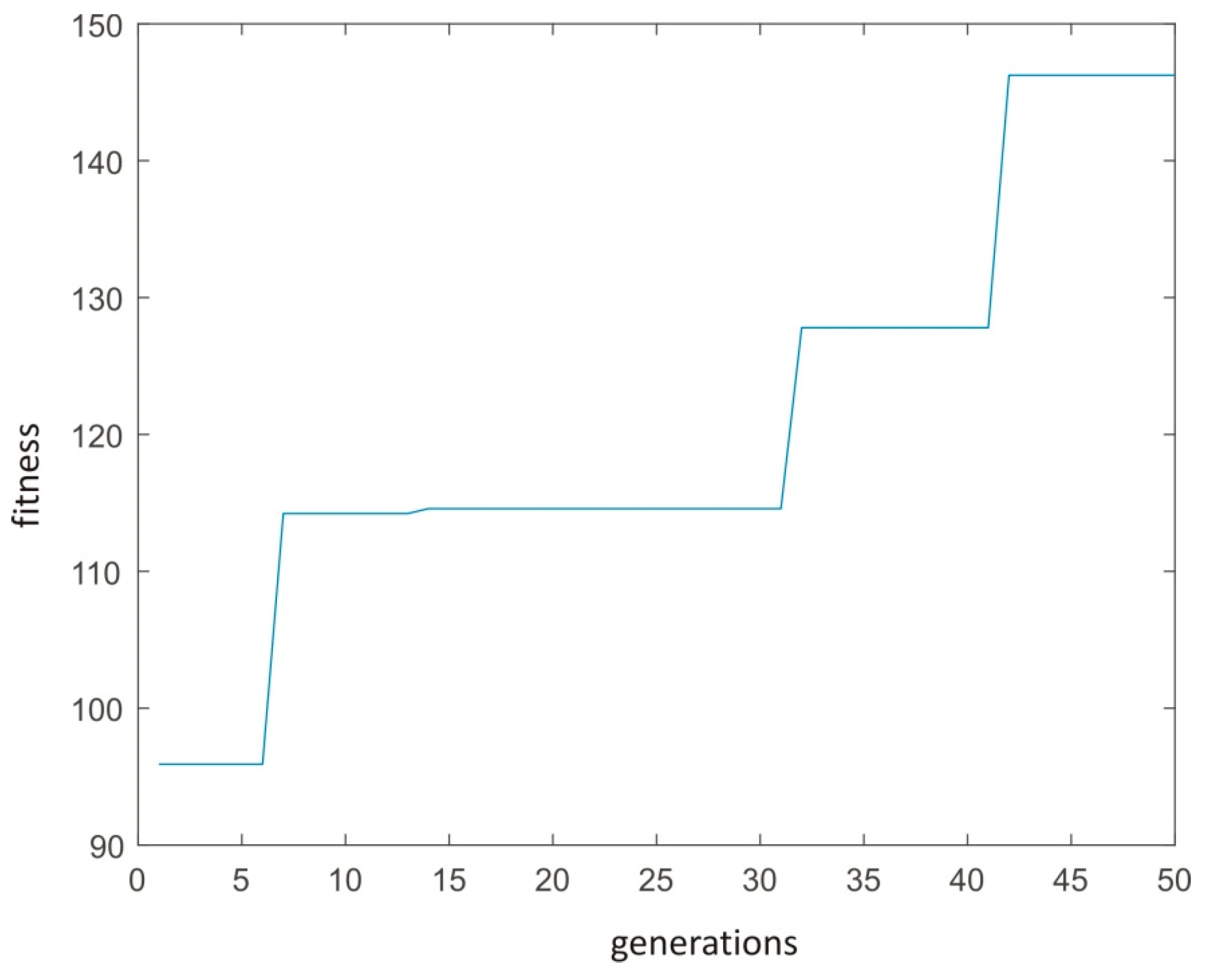
4. Computational Evaluation and Results
5. Conclusions
Author Contributions
Funding
Conflicts of Interest
References
- Panwar, N.; Sharma, S.; Singh, A.K. A survey on 5G: The next generation of mobile communication. Phys. Commun. 2016, 18, 64–84. [Google Scholar] [CrossRef]
- Locher, I.; Klemm, M.; Kirstein, T. Troster. Design and characterization of purely textile patch antennas. IEEE Trans. Adv. Packag. 2006, 29, 777–788. [Google Scholar] [CrossRef]
- Hertleer, C.; Hendrik, R.; Vallozzi, L.; van Langenhove, L. A textile antenna for off-body communication integrated into protective clothing for firefighters. IEEE Trans. Antennas Propag. 2009, 57, 919–925. [Google Scholar] [CrossRef]
- Dierck, A.; Agneessens, S.; Declercq, F.; Spinnewyn, B.; Stockman, G.J.; Van Torre, P.; Vallozzi, L.; Ginste, D.V.; Vervust, T.; Vanfleteren, J.; et al. Active textile antennas in professional garments for sensing, localization and communication. Int. J. Microw. Wirel. Technol. 2014, 6, 331–341. [Google Scholar] [CrossRef]
- Lemey, S.; Agneessens, S.; van Torre, P.; Baes, K.; Vanfleteren, J.; Rogier, H. Wearable flexible lightweight modular RFID tag with integrated energy harvester. IEEE Trans. Microw. Theory Tech. 2016, 64, 2304–2314. [Google Scholar] [CrossRef]
- Bayram, Y.; Zhou, Y.; Shim, B.S.; Xu, S.; Zhu, J.; Kotov, N.A.; Volakis, J.L. E-textile conductors and polymer composites for conformal lightweight antennas. IEEE Trans. Antennas Propag. 2010, 58, 2732–2736. [Google Scholar] [CrossRef]
- Tak, J.; Lee, S.; Choi, J. All-textile higher order mode circular patch antenna for on-body to on-body communications. Microw. Antennas Propag. 2015, 9, 576–584. [Google Scholar] [CrossRef]
- Liu, F.-X.; Kaufmann, T.; Xu, Z.; Fumeaux, C. Wearable applications of quarter-wave patch and half-mode cavity antennas. IEEE Antennas Wirel. Propag. Lett. 2015, 14, 1478–1481. [Google Scholar] [CrossRef]
- Lee, H.; Jinpil, T.; Jaehoon, C. Wearable Antenna Integrated into Military Berets for Indoor/Outdoor Positioning System. IEEE Antennas Wirel. Propag. Lett. 2017, 16, 1919–1922. [Google Scholar] [CrossRef]
- Sanchez-Montero, R.; Salcedo-Sanz, S.; Portilla-Figueras, J.A.; Langley, R. Hybrid PIFA-patch antenna optimized by evolutionary programming. Prog. Electromagn. Res. 2010, 108, 221–234. [Google Scholar] [CrossRef]
- Das, A.; Mandal, D.; Ghoshal, S.P.; Kar, R. Concentric circular antenna array synthesis for side lobe suppression using moth flame optimization. AEU Int. J. Electron. Commun. 2018, 86, 177–184. [Google Scholar] [CrossRef]
- Ustun, D.; Akdagli, A. Design of band notched UWB antenna using a hybrid optimization based on ABC and DE algorithms. AEU Int. J. Electron. Commun. 2018, 87, 10–21. [Google Scholar] [CrossRef]
- Sanchez-Montero, R.; Camacho-Gomez, C.; Lopez-Espı, P.L.; Salcedo-Sanz, S. Optimal Design of a Planar Textile Antenna for Industrial Scientific Medical (ISM) 2.4 GHz Wireless Body Area Networks (WBAN) with the CRO-SL Algorithm. Sens. J. 2018, 18, 1982. [Google Scholar] [CrossRef]
- Awl, H.N.; Abdulkarim, Y.I.; Deng, L.; Bakir, M.; Muhammadsharif, F.F.; Karaaslan, M.; Unal, E.; Luo, H. Bandwidth Improvement in Bow-Tie Microstrip Antennas: The Effect of Substrate Type and Design Dimensions. Appl. Sci. 2020, 10, 504. [Google Scholar] [CrossRef]
- Prabhaka, H.V.; Kummuri, U.K.; Yadahalli, R.M.; Munnappa, V. Effect of various meandering slots in rectangular microstrip antenna ground plane for compact broadband operation. Electron. Lett. 2007, 43, 848–850. [Google Scholar] [CrossRef]
- Hossa, R.; Byndas, A.; Bialkowski, M.E. Improvement of compact terminal antenna performance by incorporating open-end slots in ground plane. IEEE Microw. Wirel. Compon. Lett. 2004, 14, 283–285. [Google Scholar] [CrossRef]
- Zhang, Z.Y.; Fu, G.; Zuo, S.L. A miniature sleeve meander antenna for TPMS application. J. Electromagn. Waves Appl. 2009, 23, 1835–1842. [Google Scholar] [CrossRef]
- Salcedo-Sanz, S.; del Ser, J.; Landa-Torres, I.; Gil-Lopez, S.; Portilla-Figueras, J.A. The Coral Reefs Optimization algorithm: A novel metaheuristic for efficiently solving optimization problems. Sci. World J. 2014, 739768. [Google Scholar] [CrossRef]
- Salcedo-Sanz, S. A review on the coral reefs optimization algorithm: New development lines and current applications. Prog. Artif. Intell. 2017, 6, 1–15. [Google Scholar] [CrossRef]
- Langley, R.; Voudouris, K.; Batchelor, J.C. Annular ring patch antennas. In Proceedings of the IEEE Colloquium on Multi-Band Antennas, London, UK, 26 October 1992; pp. 6–11. [Google Scholar]
- Mahmoud, S.F. A new miniaturized annular ring patch resonator partially loaded by a metamaterial ring with negative permeability and permittivity. IEEE Antennas Wirel. Propag. Lett. 2004, 3, 19–22. [Google Scholar] [CrossRef]
- Bao, X.L.; Ammann, M.J. Compact annular-ring embedded circular patch antenna with cross-slot ground plane for circular polarization. Electron. Lett. 2006, 42, 192–193. [Google Scholar] [CrossRef]
- Bao, X.L.; Ammann, M.J. Dual-frequency circularly-polarized patch antenna with compact size and small frequency ratio. IEEE Trans. Antennas Propag. 2007, 55, 2104–2107. [Google Scholar] [CrossRef]
- Zhang, Y.; Hong, W.; Yu, C.; Kuai, Z.Q.; Don, Y.; Zhou, J.Y. Planar ultrawideband antennas with multiple notched bands based on etched slots on the patch and/or split ring resonators on the feed line. IEEE Trans. Antennas Propag. 2008, 56, 3063–3068. [Google Scholar] [CrossRef]
- Lee, K.F.; Yang, S.L.S.; Kishk, A.A.; Luk, K.M. The versatile U-slot patch antenna. IEEE Antennas Propag. Mag. 2010, 100, 71–88. [Google Scholar] [CrossRef]
- Hsieh, C.; Chiu, T.T.; Lai, C. Compact dual-band slot antenna at the corner of the ground plane. IEEE Trans. Antennas Propag. 2009, 57, 3423–3426. [Google Scholar] [CrossRef]
- Wu, G.; Mallipeddi, R.; Suganthan, P.N. Ensemble strategies for population based optimization algorithms—A survey. Swarm Evol. Comput. 2019, 44, 695–711. [Google Scholar] [CrossRef]
- Geem, Z.W.; Kim, J.H.; Loganathan, G.V. A new heuristic optimization algorithm: Harmony Search. Simulation 2001, 76, 60–68. [Google Scholar] [CrossRef]
- Storn, R.; Price, K. Differential Evolution—A simple and efficient heuristic for global optimization over continuous spaces. J. Glob. Optim. 1997, 11, 341–359. [Google Scholar] [CrossRef]
- Eiben, A.E.; Smith, J.E. Introduction to Evolutionary Computing; Springer: Berlin, Germany, 2003. [Google Scholar]
- Salcedo-Sanz, S. Modern meta-heuristics based on nonlinear physics processes: A review of models and design procedures. Phys. Rep. 2016, 655, 1–70. [Google Scholar] [CrossRef]
- Grassberger, P.; Procaccia, I. Characterization of strange attractors. Phys. Rev. Lett. 1983, 50, 346–349. [Google Scholar] [CrossRef]


| Variable | Range |
|---|---|
| Antenna top view | |
| U_T | [1,5] |
| U_Patch_h | [1,Lp] |
| U_Patch_AY | [0.5,(Wp-2Circle_R)/2] |
| U_Patch_AX | [0.5,Lp/2-U_Patch_W-Circle_R] |
| U_Ah | [1,(Wp-7Mean_A-8Mean_W-2U_T)/2] |
| U_L | [0.5,Wp] |
| U_Patch_W | [1,5] |
| Circle_R | [11,Wp/2] |
| Circle_Angle | [0.5,180] |
| Circle_S | [3,5] |
| Cirlce_CT | [1,5] |
| Circle_T | [3,5] |
| Lp=60mm; Wp=90mm | |
| Antenna ground plane | |
| Mean_W | [1,2.7] |
| Mean_A | [1,10] |
| Mean_h | [1,Lp] |
| U_AV | [1,(Lp-Mean_h-2U_T)/2] |
| Algorithm Step | Pseudo-Code for the CRO Algorithm |
|---|---|
| 1 | Require: CRO algorithm parameters |
| 2 | Ensure: An optimal feasible individual (best antenna design) |
| 3 | Initialize the algorithm and CRO parameters |
| 4 | for each iteration of the simulation do |
| 5 | Update values of CRO parameters: predation probability, etc. |
| 6 | Broadcast spawning and Brooding operators |
| 7 | Settlement of new corals |
| 8 | Predation process |
| 9 | Evaluate the new population in the coral reef |
| 10 | end for |
| 11 | Return: the best individual (final solution) from the reef |
| Algorithm | Best Fitness |
|---|---|
| CRO-SL (two frequency bands) | 146.24 |
| CRO-SL (three frequency bands) | 155.03 |
| Evolutionary Algorithm | 130.05 |
| Frequency (GHz) | Gain (dBi) |
|---|---|
| 0.8 | 2.734 |
| 2.2 | 4.793 |
| 3.5 | 8.344 |
© 2020 by the authors. Licensee MDPI, Basel, Switzerland. This article is an open access article distributed under the terms and conditions of the Creative Commons Attribution (CC BY) license (http://creativecommons.org/licenses/by/4.0/).
Share and Cite
Camacho-Gomez, C.; Sanchez-Montero, R.; Martínez-Villanueva, D.; López-Espí, P.-L.; Salcedo-Sanz, S. Design of a Multi-Band Microstrip Textile Patch Antenna for LTE and 5G Services with the CRO-SL Ensemble. Appl. Sci. 2020, 10, 1168. https://doi.org/10.3390/app10031168
Camacho-Gomez C, Sanchez-Montero R, Martínez-Villanueva D, López-Espí P-L, Salcedo-Sanz S. Design of a Multi-Band Microstrip Textile Patch Antenna for LTE and 5G Services with the CRO-SL Ensemble. Applied Sciences. 2020; 10(3):1168. https://doi.org/10.3390/app10031168
Chicago/Turabian StyleCamacho-Gomez, Carlos, Rocio Sanchez-Montero, Diego Martínez-Villanueva, Pablo-Luís López-Espí, and Sancho Salcedo-Sanz. 2020. "Design of a Multi-Band Microstrip Textile Patch Antenna for LTE and 5G Services with the CRO-SL Ensemble" Applied Sciences 10, no. 3: 1168. https://doi.org/10.3390/app10031168
APA StyleCamacho-Gomez, C., Sanchez-Montero, R., Martínez-Villanueva, D., López-Espí, P.-L., & Salcedo-Sanz, S. (2020). Design of a Multi-Band Microstrip Textile Patch Antenna for LTE and 5G Services with the CRO-SL Ensemble. Applied Sciences, 10(3), 1168. https://doi.org/10.3390/app10031168