1. Introduction
The Shaping the Future of Construction—A Breakthrough in Mindset & Technology, jointly published by the World Economic Forum and the Boston Consulting Group, reports the impact of integrated building information modeling (BIM) on the future construction market is enormous [
1]. In fact, most of the advanced project delivery methods such as construction management (CM) at risk, pre-construction services (Precon), and integrated project delivery (IPD)—which are being piloted in the domestic construction market—use BIM as a core technology. BIM is an intelligent information system that is more than a physical three-dimensional model [
2]. In Korea, Ministry of Land, Infrastructure and Transport have recently announced the “smart construction technology roadmap” to innovate construction productivity and enhance safety [
3]. This roadmap aims to automate design based on BIM.
However, at the design stage, Despite the results of previous studies on productivity improvement based on 3D model, 2D-drawing-based documentation method is still commonly used due to high BIM investment cost and lack of skilled BIM staff [
4]. This approach is difficult to intuitively check a large amount of drawings, which leads to frequent design errors and changes, as well as excessive work [
5]. Existing studies have found the effects of various BIM applications, such as the effects of design methods to convert 2D drawings to 3D model [
6], BIM-based design validation to review design quality [
7], and the economic impact of design errors on construction companies [
8]. These studies point out that the low quality of design drawings created with documentation method based on 2D drawing results in rework and schedule delay [
7,
8].
The productivity of documentation method of a number of drawings that is relevant to all tasks is essential to the analysis of construction productivity [
9]. In the previous study, BIM-based design validation was used to systematize the types of design errors and quantitatively analyze the effects [
7,
8]. Although high quality drawings are required for advanced construction projects with off-site construction [
10], DfMA methodology [
11], and additive manufacturing [
12], productivity analysis studies on the documentation method have not been dealt with frequently. While some studies have compared the productivity of CAD and BIM, it is difficult to find specific productivity analysis data for documentation methods in these studies [
13].
The purpose of this study is to quantitatively compare the productivity of 2D-drawing-based documentation method and 3D-model-based documentation method through case analysis of plant facility. In addition, this study investigates the effects of recycling of object-based libraries in 3D-model-based documentation.
2. Literature Review
2.1. Productivity in Off-Site Construction
In traditional on-site construction, engineered to order (ETO) components (e.g., structural steel frames, structural precast concrete pieces, façade panels, etc.) are prefabricated at the factory by the supplier. Depending on the level of system integration and engineering, emerging ETO components include fully integrated building modules (e.g., modular construction), fully integrated sub-assemblies (e.g., prefabricated units), efficient structural systems (e.g., structural steel, total precast buildings), integrated architectural multi trade systems (e.g., slabs, walls fitted with services), integrated MEP multi trade systems (e.g., MEP racks, machines with services), prefabricated components (e.g., structural ETO, architectural ETO, MEP ETO), etc. [
2].
Since off-site construction involves the manufacturing process, it is important to secure the quality of the design, which is a preliminary process [
14]. Due to the large impact of design quality on manufacturing and construction, project delivery methods (e.g., IPD, CM at Risk, Precon) of early contractor involvement (ECI) type have been tried [
15,
16,
17]. The goal of this procurement approach is to develop a complete plan that ensures the quality of the design drawings.
Productivity can be described as output versus input. From an economic point of view, productivity is defined as carrying out more achievement per unit resource [
18]. Alazzaz and Whyte (2014) [
19] analyzed resource development, worker involvement, process improvement and task recognition as having a significant impact on offsite construction productivity. Meiling et al. (2012) [
20] focused on improving the process among the factors affecting offsite manufacturing. Mao et al. (2015) [
21] identified obstacles to off-site construction, including traditional design practices [
22], lack of standardized manufacturing components [
23,
24], and lack of skilled technicians [
25].
Methods for measuring and improving productivity at construction sites include measuring and interpreting work and crew effectiveness (e.g., field rating, work sampling, five-minute rating, etc.), field surveys (e.g., foreman delay survey, craftsman questionnaire, etc.), the method productivity delay model, charting techniques, simulation modeling, and analysis [
8]. While many researchers have been working to measure and improve productivity, productivity analysis of the entire process is a very difficult research topic because the construction process is very complex and many engineering professionals are involved [
26]. In particular, it is very difficult to collect research data on the productivity of real-world construction projects depending on the application of BIM [
7]. In this regard, research is needed to measure and improve productivity, focusing on micro tasks that are influential in the construction process [
27]. The purpose of this study is to analyze the productivity of documentation tasks that directly affect all tasks throughout the construction lifecycle.
2.2. Roles of BIM for Construction Project
The main feature of BIM is to create a 3D-model-based on the object information, and take advantage of the visualization, simulation, and analysis using 3D model [
28]. Also, BIM is used for various tasks such as reviewing design errors and interference [
29], calculating quantities [
30], documentation [
31], scheduling [
32], and 3D logistics analysis [
33].
During the design phase, documentation that provides information in connection with manufacturing and construction is very important. In particular, it is very important to improve the productivity of the documentation of structural steel frame that the member is to be pre-fabricated in the factory and is delivered into the construction site [
34]. Although the information for manufacturing should be produced without design errors and delivered to the fabricator, a 2D-drawing-based documentation method is still commonly used. On the other hand, the documenting method of extracting plan, elevation, and section views required for documentation from the 3D model can generate more accurate information than the documentation method based on 2D drawing.
However, it is difficult to find a study comparing the productivity of the documentation method of extracting 2D drawings from the 3D model and the documentation method of directly creating 2D drawings without the 3D model. Therefore, this study aims to compare the productivity of 3D-model-based documentation with that of 2D-drawing-based documentation.
2.3. 3D-model-based Documentation
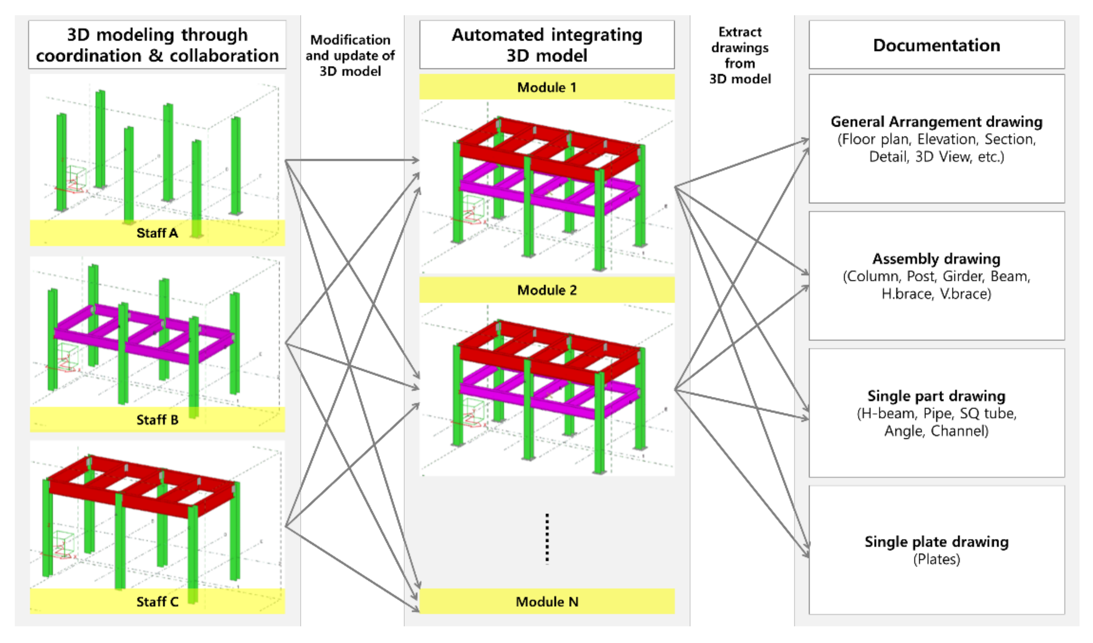
A 3D model is created from a combination of various object libraries that contain shape and property information. In particular, the 3D model for prefabrication provides the function to create not only design drawings but also drawings required for manufacturing and construction. The drawings of the structural steel frame consist of general arrangement drawing, assembly drawing, single part drawing, and single plate drawing. The documentation method using the 3D model extracts various 2D views from the 3D model to create a drawing including information about plans, elevations, and sections. The biggest advantage of this method is that when the update of design change is reflected in the 3D model, the related 2D view is changed automatically. This can greatly reduce drawing modification time compared to 2D drawing-based documentation.
Previous studies on BIM based documentation were investigated as follows. Oh et al. (2013) [
35] proposed a standard for preparing BIM-based structural drawings, and Park et al. (2016) [
36] proposed a standard for drawing requirements information for preparing BIM-based architectural permit design documents. Kim et al. (2018) [
37] established criteria to distinguish what should be modified in the BIM model from what should be corrected in the CAD drawings in order to minimize inefficient duplication and additional work when creating a BIM-based detailed design drawing. Kim et al. (2018) [
38] proposed a process for utilizing information extracted from BIM for steel construction. Eom & Shin (2010) [
39] studied the modeling automation of complex steel joints, and Eom & Shin (2011) [
40] studied the development of interfaces to improve interoperability between design processes. Shin & Yang (2009) [
41] proposed a construction drawing automatic process for steel structures. However, empirical research on the productivity of 3D-model-based documentation is lacking.
Meanwhile, research on prefabrication, digital fabrication processes, and productivity for atypical buildings and complex parts is increasing in recent years. Prefabrication and digital fabrication, usually done in factories, are generally classified as additional manufacturing and is based on computer-based design and robotic-based production processes [
42]. The Bilbao Guggenheim Museum project automatically generated approximately 50,000 2D drawings from 3D models and provided them to project participants [
43]. Jang and Lee (2018) [
44] analyzed the process, productivity, and economics of the pre-fabrication method for BIM-based MEP racks. Nahangi and Haas (2014) [
45] proposed a 3D methodology for manufacturing quality control of pipe spools.
However, these studies cannot provide the productivity analysis results of 3D-model-based documentation method compared to 2D-drawing-based documentation method. BIM handbook analyzed the time of modeling and reinforcement detailing drawing production through three reinforced concrete building projects [
2]. The analysis showed higher productivity than 2D method. Neelamkavil and Ahmed (2012) [
13] used BIM in the design phase to reduce input time to output for productivity analysis. Kaner et al. (2008) [
46] analyzed the drawing work using the BIM and CAD methods as the time spent in drawing for the productivity analysis of drawing generation. In order to analyze the productivity of the documentation method, the number of engineers who worked on the drawing work, the working time, and the total number of drawings are needed. However, not many structural engineers can create drawings using 3D-model-based documentation. In addition, it is difficult to obtain productivity data on actual projects required for research. Therefore, this study is to compare existing 2D-drawing-based documentation method with 3D-model-based documentation method through case analysis of EPC project.
3. Structural Steel Frame Documentation Process
3.1. 2D-Drawing-Based Documentation
The EPC project consists of steel and related members. Therefore, fast and accurate delivery of production drawings has a big impact on project performance. In the 2D-drawing-based documentation method, the structural engineer reviews the design drawings in 2D CAD and creates a general arrangement drawing. General arrangement drawings include floor plans, elevations, cross sections and details. General arrangement drawings contain various information for construction such as list and size of members, installation coordinates and level. Refer to the general arrangement drawings used for the installation of structural steel frame in the field and create the 2D drawings required for prefabrication. 2D drawings include assembly drawings, single part drawings, and single plate drawings. Separately drawn drawings are cross reviewed to perform integrity checks. In addition, the quantity calculation for the members required for construction is performed.
In the prefabrication phase, single parts and single plates are produced based on the previously drawn drawings. Single part drawings include H-BEAM, pipe, SQ tube, angle, and channel. Structural engineers manually code and mark assembly locations for the use of CNC machines for cutting and making of hole. In the case of single plate drawings, nesting and CNC laser machining to produce the plate are performed by manual coding. Such manual work can cause schedule delays, potential errors, and loss of raw materials.
3.2. 3D-Model-Based Documentation
3D-model-based documentation is a collaborative approach centered on 3D models. First of all, project participants jointly perform 3D modeling work. Once the master 3D model is created, the drawing work using the 3D model is performed as shown in
Figure 1. Documentation method using 3D model can check design error such as logical error, redundancy and omission in 3D modeling process in advance. In addition, by performing the interference check using the 3D model, it is possible to ensure the integrity of the 3D model directly connected to the quality of the drawings. In this way, time for reviewing the quality of the calculated drawings can be saved. Once a 3D model with integrity is created, a shop drawing containing 2D or 3D information required for factory manufacturing can be parametrically created using the 3D model. The generated shop drawing adds a bit of information needed for production. In addition, quantity information can be quickly calculated based on information included in each member object of the 3D model. The calculated quantity information can be attached to the shop drawing.
In the manufacturing stage, the information contained in the 3D model can be used for manufacturing using a CNC (computerized numerical control) machine. In other words, data necessary for cutting, drilling, welding, and automatic assembly position of the member can be obtained. It can also be used as nesting data that automatically places members in the factory. The 3D-model-based documentation approach saves time and money by integrating site and factory processes compared to the 2D-drawing-based documentation approach. In addition, by utilizing a 3D model with integrity, accuracy and productivity can be improved. Finally, raw materials can be saved through automation (e.g., nesting data). On the other hand, if the complexity of the building is high or large, there may be a limit in constructing a 3D model with integrity. Because of this, few studies analyze the productivity of the micro task of extracting documentation from 3D model. In particular, very few studies compare the 2D-drawing-based documentation approach to the 3D-model-based documentation approach for the same project. The purpose of this study is to analyze the productivity of 3D-model-based documentation method through case analysis of structural steel frame.
4. Productivity Analysis of 3D-Model-Based Documentation
4.1. Case Study
4.1.1. Project Description
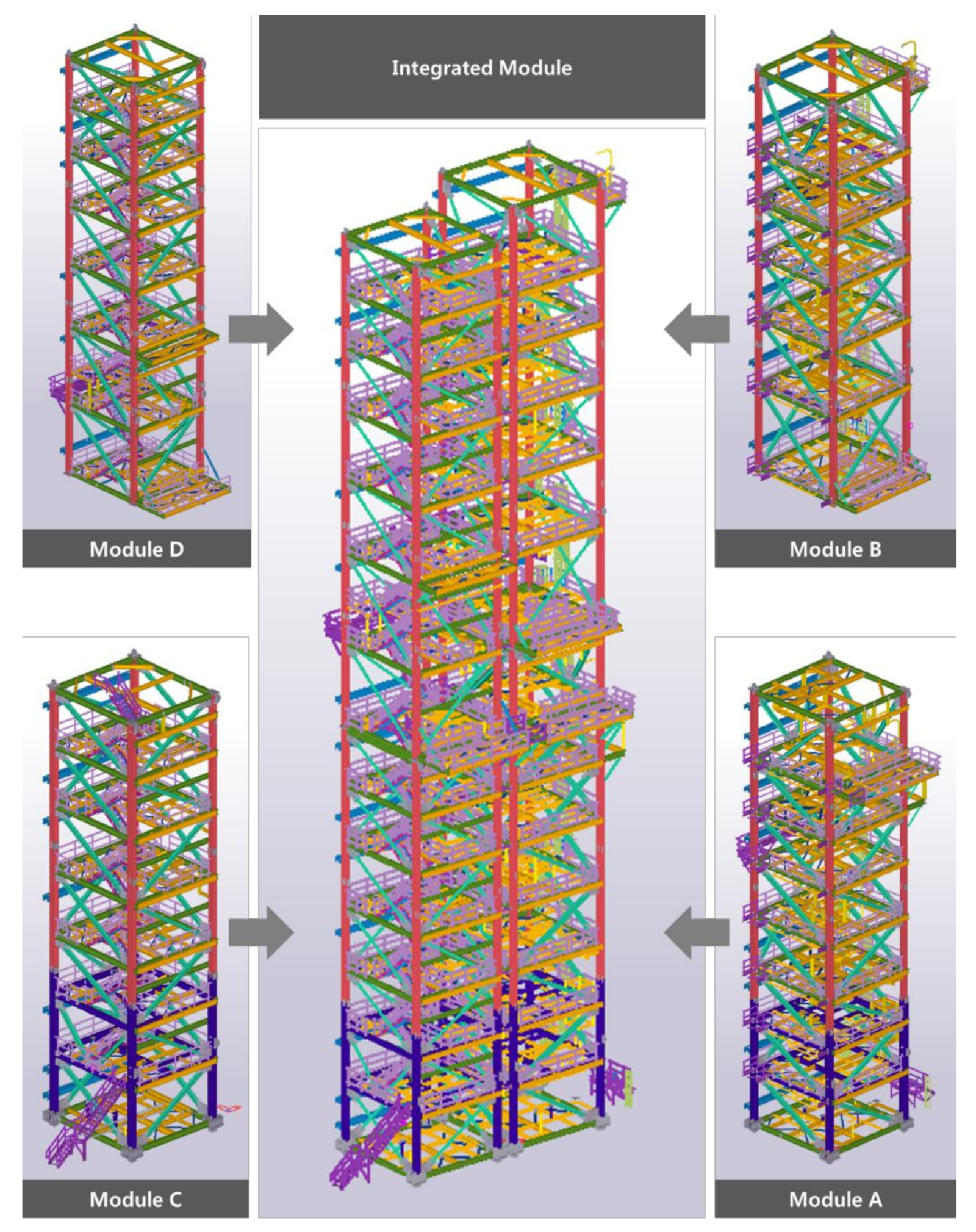
The case of this study is a plant facility consisting of four modules as the Engineering Procurement Construction (EPC) project as shown in
Figure 2. 3D modeling was performed based on the design documents provided by the client, and the drawings needed for the fabrication were made using the 3D model. The whole module consists of four modules. Module A (180.96 Ton) consists of 1965 production drawings, Module B (120.06 Ton) consists of 1216 production drawings, Module C (114.06 Ton) consists of 939 drawings, and Module D (120.94 Ton) consists of 1175 drawings. A total of 5295 production drawings were delivered.
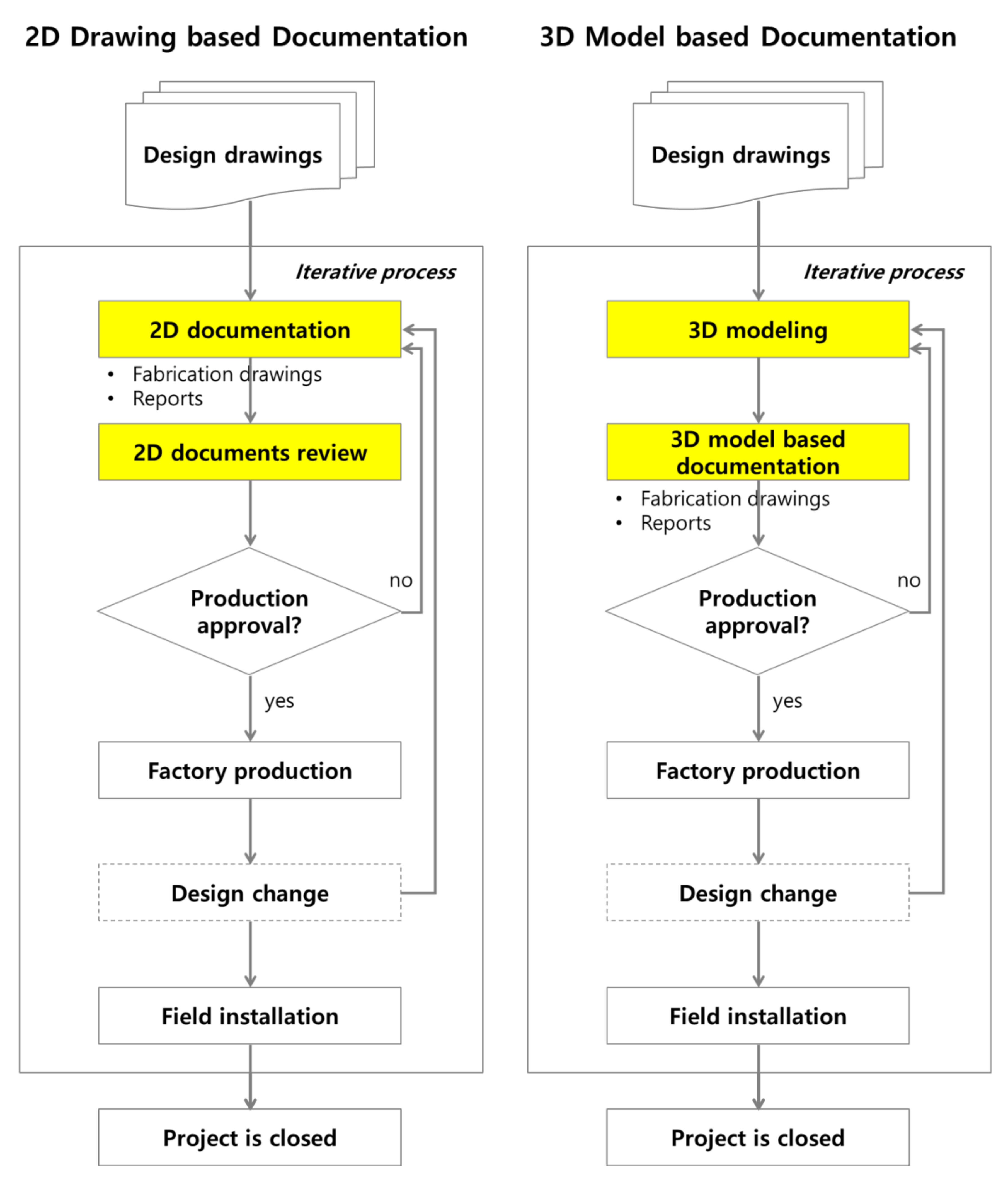
The case project was conducted from December 2014 to September 2015. The detailed process is as shown in
Figure 3. 3D modeling proceeds after the process of reviewing and inquiring design drawings from the client. Fabrication drawings (e.g., general arrangement drawings, assembly drawings, single part drawings, single plate drawings) and reports (e.g., information including drawing number, part number/type/quantity/size/weight, painted area, bolt type/quantity, etc.) are generated after completion of 3D modeling. These documents are submitted for approval of client. The drawing productivity comparison data presented in the case project is based on the first drawing delivery. Correction and re-delivery of drawings are repeated due to design changes and various factors after delivery, and factory production starts when the final production approval is obtained from the client.
Design changes may occur even after the final production approval, and the drawings must be immediately modified. In general, all personnel or some will be put into a new project because the time spent on the project is reduced after the final production approval. The prefabricated members are installed on site, and factory production and field installation take place simultaneously. If an issue occurs at this time, the drawing may need to be modified. When this process is completed, the project is closed.
The 2D-drawing-based documentation method is the same as described above except for the presence of a 3D model. Drawing modifications and deliveries are repeated many times during the project. If this process is based on 2D drawing, it takes a lot of time and frequently causes design errors. However, in case projects using 3D-model-based documentation, modification time, and design errors were reduced. In addition, an accurate 3D model that reflected design and engineering changes was able to automatically calculate the data (e.g., drawing number, part number/type/quantity/size/weight, painted area, bolt type/quantity) needed for manufacturing. In addition, the 3D model made it easy to identify whether the modifications were reflected.
As shown in
Figure 3, the documentation process, which is a unit of work, is iterative and complex. Therefore, detailed time measurement of all tasks is not possible for case analysis. Therefore, in this study, working hours were collected according to the types of fabrication drawings through expert interviews with engineers who participated in actual work. This study was conducted by interviewing the staff in charge of the design office who performed the project to collect productivity comparison analysis data of 3D-model-based documentation method and 2D-drawing-based documentation method. The 2D-drawing-based documentation method is based on the case of using AutoCAD, and the 3D-model-based documentation method is based on the case of using TEKLA. A total of four people were used for the documentation work of the case project, and it was assumed that 8 h were worked per day.
The engineer’s experience is more than 5–10 years of experience, and they are familiar with both methods of documentation. Engineers with less than five years of experience usually have individual differences in competence that affect the schedule, quality of the project, but engineers with at least five years of experience are recognized as skilled engineers in carrying out the project. Labor costs can be on average 1.25- to 1.5-times higher for engineers who can use 3D models than engineers who use only 2D drawing. However, labor costs are based on additional factors such as non-technical positions, project management skills, foreign language skills, and certifications. Therefore, there is a limit to use as a basis for comparing documentation productivity of engineers using 2D drawing and engineers using 3D model.
As discussed above, this study established some prerequisites to analyze the productivity according to the difference of documentation method only with time index. First, engineers were selected for at least five years of work experience in order to select interviewees for gathering productivity data. Second, it is assumed that there is no difference in the quality of the fabrication drawings required by the client according to the two documentation methods. In fact, interviewees in the case project were able to do both ways of documentation and had the capacity to meet both the client’s requirements for fabrication drawing quality. Third, productivity data is difficult to obtain when considering design changes that occur frequently. Therefore, this study utilized the productivity data of the production time of the first fabrication drawing delivered to the client. Based on this premise, this study aims to compare and analyze productivity by focusing on documentation time, 3D modeling work time, and 2D documentation review time.
4.1.2. Data Collection and Classification
The drawings required for the production of a case project consisting of four modules are shown in
Table 1. Looking at the types of drawings, most of them are assembly drawing (35.09%), single part drawing (38.92%), and single plate drawing (24.74%).
Table 2 shows the work productivity data per sheet in two documentation methods.
Table 3 analyzes the documentation time according to the type of drawing by using the productivity data of
Table 2. In the case of general arrangement drawing, the working time per drawing was 90 min and 60 min. However, due to the small number of drawings, the proportion of total work time was relatively low at 8.58% (5940 min) and 11.80% (3960 min). On the other hand, in the case of assembly drawing, not only does a lot of work time is put in comparison with single part drawing and single plate drawing, but also a large number of drawings. Therefore, the proportion of total documentation work time was very high at 67.08% (46,450 min) and 72.00% (24,154 min). Therefore, this study aims to compare the productivity of 2D-drawing-based documentation method and 3D-model-based documentation method for assembly drawing extraction.
4.2. Productivity Analysis of Assembly Drawing Extraction
4.2.1. Detailed Task Comparison in Documentation
(1) 2D-Drawing-Based Documentation vs. 3D-Model-Based Documentation
In the case of this project, the 3D-model-based documentation method was used. In contrast to the 2D drawing-based documenting method, four engineers with the same engineering competency were invested and analyzed the time taken to produce the production drawing. Fabrication documents (e.g., general arrangement drawing, assembly drawing, single part drawing, single plate drawing) using AutoCAD are used on site and must be delivered prior to fabrication of the part. Assembly drawing, single part drawing, and single plate drawing are prepared by referring to general arrangement drawing such as floor plan, elevation, section, and detail. After that, a lot of time is spent to cross-check the completed production drawings to ensure the integrity of the drawings. Therefore, the 2D-drawing-based documentation method is divided into documentation work and reviewing drawings. Cooperation is required in the cross-checking of individually generated 2D fabrication drawings. However, human error is very likely to occur when comparing the consistency of a large amount of 2D fabrication drawings without a 3D model.
On the other hand, the 3D-model-based documentation method using TEKLA does not take time to examine the integrity of the drawing because the view extracted in the relevant drawing is created from the 3D model. In 3D modeling work of Module A–D, 3D model for Module A was first constructed according to fabrication documents delivery schedule. By sharing the 3D model, four engineers simultaneously perform 3D modeling for each part or floor connection for the same module. In the 3D modeling process, if the modeling work is interrupted and collaboration is difficult, some personnel perform 3D modeling work on the subsequent module. In order to deliver the fabrication documents, detailed information on the joints is required for each module. Therefore, when the 3D modeling work for the main joints for one module unit is completed, one person additionally proceeds with 3D modeling for the detail area. The remaining three engineers will work on the 3D modeling of modules B–D. When detailed 3D modeling for Module A is completed, a total of four engineers perform documentation editing for 3D modeling completed module. 3D modeling work and 3D-model-based documentation can flexibly distribute the manpower according to the delivery date and situation, enabling efficient work. As mentioned above, this study was analyzed the productivity data for assembly drawing, which has the highest proportion of drawing work in
Table 4.
As a result of the analysis, in the 2D-drawing-based documentation method, the documentation time per unit drawing for column and girder was 60 min and 55 min, respectively. The documentation time per unit drawing for BEAM and BRACE/POST was relatively low as 25 min and 10 min, respectively. The assembly drawing documentation time for BEAM and Girder was 9500 and 4015 min, respectively, accounting for 56.26% and 23.78% of total work time. In the 3D-model-based documentation method, the documentation time per unit drawing for Column and Girder was 40 min and 40 min, respectively. However, productivity is improved by 33.33% and 27.27% compared to 2D-drawing-based documentation method. The documentation time per unit drawing for BEAM and BRACE/POST was 10 min and 5 min, respectively, improving 60.00% and 50.00% productivity compared to 2D-drawing-based documentation method. The assembly drawing documentation time for BEAM and Girder was 3800 min and 2920 min, respectively, accounting for 44.01% and 33.82% of total work time.
(2) 2D Documentation Review vs. 3D Modeling
The 2D-drawing-based documentation approach puts a lot of work into documentation review to review the integrity of individual drawings. In contrast, the 3D-model-based documentation approach enables engineers to coordinate and collaborate on the 3D modeling task of creating a master 3D model. In this study, the time spent on each task is analyzed in
Table 5. According to the analysis results, the time spent by the engineer to review the integrity of the drawings was equally investigated. This means that it is difficult to guarantee 100% of the integrity of the drawing through the 2D-drawing-based documentation method even if the quality improvement effort of cross-reviewing each type of drawing is repeatedly performed.
On the other hand, in the 3D modeling based documentation method, 3D modeling work time for Module A was 10 days, which is much higher than 3D modeling work time for Modules B–D. This is because it takes a lot of time to build libraries that are commonly used in the project when 3D modeling work for the first module, and to establish the standards for various types of information included in the drawings and templates according to the types of drawings. When the document is based on the 3D model, the integrity of the drawing and calculation information is secured according to the integrity of the 3D model. In addition, it can proactively cope with revisions to design and engineering that occur after the creation of primary fabrication documents. In other words, when the 3D model is modified, the view is updated due to the parametric characteristics provided by BIM software, and the fabrication documents including the view is automatically updated. Documenting method using 3D model can save work time and reduce human error. Incidentally, the accuracy and efficiency of the production can be improved by generating the file input to the CNC machine. In the installation and construction process, various 3D model views can support scheduling to make the process easier to understand.
4.2.2. Productivity by Module
The main difference between the 2D-drawing-based documentation method including documentation and documents review and the 3D-model-based documentation method including 3D modeling and documentation is the existence of 3D model. Commercial BIM software enables 3D models, views, and sheets to be linked based on objects, thus ensuring the consistency of the production drawings under the premise that 3D models are created accurately. For this reason, the productivity of 3D-model-based documentation is higher than that of 2D-drawing-based documentation. However, no comparisons were made between the two types of documentation time, including the time spent on document review and 3D modeling.
Table 6 shows the results of converting documents review and 3D modeling to the fabrication documents of each module using the productivity data in
Table 5. The second column and the seventh column in
Table 6 represent the working time for documents review and 3D modeling per one drawing. As a result of adding this to documentation time, the productivity of 3D-model-based documentation method was 31.37–33.20% for general arrangement drawing, 40.57–46.65% for assembly drawing, 25.75–51.67% for single part drawing, 42.47–66.87% for single plate drawings improved. It can be concluded that the method of extracting multiple drawings from the 3D model has a great influence on this productivity analysis.
5. Discussion
This study compared the productivity of documentation methods using 3D models with the documentation methods using 2D drawings. Existing studies have also been carried out on the premise of the advantage of the 3D model drawing method [
42,
44,
47]. Lee et al. (2019) [
42] analyzed the productivity of documentation of more than 30,000 fabrication documents for the irregular shaped building. In addition to the engineer’s documentation work, technologies such as automated algorithm and robotics using CNC machine were considered in the productivity analysis of documentation. Therefore, there is a limit to purely analyzing the engineer’s productivity for documentation. Jang and Lee (2018) [
44] analyzed the process, productivity and economics of multi-trade prefabrication based on BIM. However, it does not provide productivity data for producing fabrication drawings using 3D models. Yoo et al. (2019) [
47] analyzed the effects of BIM-based steel construction management from the perspective of SMEs and examined the merits of the documentation method based on the 3D model. However, the number of documents extracted from the 3D model is insufficient to discuss productivity. On the other hand, this study divides the productivity of 5295 drawings into two documentation methods.
The following are the implications and limitations of the study comparing the productivity of 2D-drawing-based documentation method and 3D-model-based documentation method, in which engineers perform all documentation tasks. First, the documentation method that extracts the shape (e.g., plan view, elevation view, section view, etc.) and property (e.g., member list, member size, etc.) information required for the documentation of general arrangement drawing, assembly drawing, single part drawing, and single plate drawing from the 3D model has been found to improve the working time significantly. However, in addition to the 3D modeling and documentation tasks, there is also a task of continuously checking the consistency of the 3D model and reviewing and verifying the shape and property information extracted from the documentation. However, this study does not reflect this task in productivity measurement.
Second, 3D modeling work is performed repeatedly, not just once during the construction project. In this study, 3D modeling work time was analyzed based on the experience of the engineers who produce shop drawings. However, assuming that the integrity of the 3D model is secured, the 3D modeling time spent on Module A and Modules B–D fully demonstrates the learning effect of repeated use of libraries. In future studies, analyzing the productivity of 3D modeling and documentation when the 3D models and libraries built in the case project of this study were recycled into a new project can provide a more accurate understanding of the learning effect of a 3D-model-based documentation method.
Third, a quantitative basis for the work time per unit drawing was provided according to the type of manufacturing drawings. Productivity data collected by interviewing shop drawing engineers with more than 5 to 10 years of experience analyzed working time for documentation of general arrangement drawing, assembly drawing, single part drawing, and single plate drawing. In particular, the documentation productivity data of columns, girder, beam, and brace/post of the assembly drawing, which takes up a large part of the total documentation work time, are presented. This productivity data is expected to be used as productivity data for subsequent studies.
Finally, the data from this study can be used to develop a plan for human resource allocation during the design phase of off-site construction. In other words, if manpower using the productive 3D-model-based documentation method is allocated, less manpower is needed, and documentation time can be shortened and design quality can be improved.
6. Conclusions
In this study, empirical comparative analysis of 2D-drawing-based documentation method and 3D-model-based documentation method for the fabrication documents of structural steel frame was performed. This study quantitatively analyzed the advantages of 3D modeling and 3D-model-based documentation method. In the initial work, productivity was not greatly improved due to the establishment of working standards and libraries for 3D modeling, but it was confirmed that the productivity could be improved through repeated use. Based on this study, the advantages and expected effects of 3D-model-based documentation method are summarized as follows.
First, it is possible to respond quickly and accurately to design changes that frequently occur in construction projects. In other words, the productivity of 3D modeling work is improved through collaboration and repeated use of 3D model elements, and the productivity of documentation is increased by automatically modifying the view and sheet associated with the 3D model. Second, the 3D-model-based documentation approach can directly contribute to design and construction automation. For example, in the manufacturing process of steel members that require simple repetitive work and mass work, productivity can be greatly improved when algorithm-based design and CNC machine are used for production. In addition, automatic marking of the assembly position of the main member can prevent waste of unnecessary manpower and raw materials. Incidentally, it is expected to improve the accuracy and quality of work and to reduce the number of workers. Third, the improvement of communication between project participants will reduce the use of paper drawings consumed in the field and reduce the waste generated in producing parts.
This study quantitatively analyzes the productivity of the documentation method for the fabrication of four repetitive modules. However, case analysis of a single construction project has limitations of generalization. In future studies, it is necessary to analyze the productivity of the 3D-model-based documentation method more clearly through case analysis of multi construction projects. In addition, as the construction industry gradually introduces techniques (e.g., additive manufacturing) and methods (e.g., design for manufacturing and assembly, DfMA) of manufacturing industry into production, the results of this study can provide direct research data on the productivity and quality of prefabrication. In addition, the results of the drawing method productivity, which can be a profit factor of BIM from the micro perspective presented in this study, can contribute to facilitating the transition from the traditional 2D-drawing-based design process to the 3D-model-based design process.


