1. Introduction
Recently, pneumatic actuators are used in various robot systems due to their high mass power ratio and flexibility. To realize the positioning of pneumatic actuators with high precision and short response, many studies on pneumatic servo systems are conducted to date [
1,
2,
3,
4,
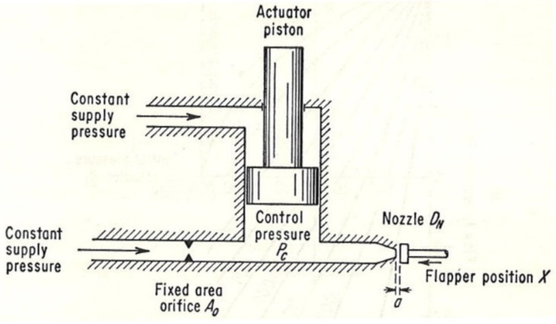
5]. In pneumatic servo systems including pneumatic robot systems, pneumatic servo valves are important components that determine the overall performance of the system. The most commonly used servo valves are broadly divided into nozzle flapper-type servo valves and spool-type servo valves [
6], whose overall structures are shown in
Figure 1 and
Figure 2. The structure of the nozzle flapper-type servo valve is such that atmospheric release exists at all times, and thus, air consumption is high. The spool-type servo valve consumes less air as compared to the nozzle flapper-type servo valve. However, there is loss due to leakage from the sliding portion gap of the spool. When you try to use a small compressor, which can be embedded in the pneumatic system, the leakage amount can be a significant problem. Therefore, when a large number of servo valves are used in the systems that requires small compressors (for e.g., multi-degree-of-freedom robot systems), the consumption of air due to leakage from valves becomes a significant problem. Decreases in leakage from the servo valve and air consumption of the complete system aid in solving these problems and saving energy.
Previous studies have developed a servo valve that reduces leakage by increasing the amount of overlap of the spool-type valve [
7]. However, the structure of such valves consists of a sliding part in the flow path, and thus, it is difficult to completely eliminate the leakage. Studies on valves have also examined using vibration-driven poppets as valves without leakage to the exterior [
8,
9,
10]. However, it is difficult to adjust the vibration-driven flow rate in such valves, and they are not suitable for a robot system that requires precise control.
Alternatively, it is conceivable to use a peristaltic pump or pinch-type valve by using an elastic tube to suppress leakage to the exterior. In a pneumatic robot system, controlling enough flow rate with high speed is required, and it is not better to use pumps. On the other hand, various valves are already available as products to adjust the amount of tube blockage by a motor or a solenoid and are widely used in applications where blood and chemical liquids are controlled, and contamination is not permitted. In the microfluidics field, pinch valves that do not use tubes are actively examined [
11,
12]. However, none of the valves are intended for use in high-speed and high-precision pneumatic servo systems, and characteristics in the flow rate control are not clarified. Additionally, any existing valve corresponds to a two or three-way valve, and it is unable to control a double acting pneumatic actuator used for robot systems by using a single valve. A four-way valve is required to drive the double-acting pneumatic cylinder as a single unit, and a high-speed and high-accuracy response is required to operate it as a servo system. As a research example, Akagi et al. developed a pinch-type servo valve by using the bending of a tube [
13]. Although it was wearable and exhibits low mass, its responsiveness is insufficient for use in a precise robot system.
Therefore, we have developed a four-way pinch type pneumatic servo valve using a cam mechanism to realize a leakage free, precise, and high-response pneumatic servo valve that is suitable for use in a robot system [
14]. However, the sensitivity of the flow rate relative to the cam angle was low around the neutral cam position. Additionally, the actual reduction effect of the air consumption was not evident, and the durability of the tube was a concern.
In the present study, we newly develop a four-way pinch valve with an improved cam mechanism and a fine offset tuner. Furthermore, we evaluate the actual air consumption and durability and fundamental performances to verify the effectiveness of the proposed valve. As a result, we could realize responsiveness until 30 Hz with a high flow rate sensitivity against the cam angle.
The rest of the paper is organized as follows.
Section 2 details the structure of the prototype valve.
Section 3 describes an experiment for evaluating the flow rate characteristics. In
Section 4, the dynamic characteristics for the cam angle control are shown.
Section 5 describes the position control of a pneumatic cylinder by the developed valve and its performance evaluation. In
Section 6, the results of durability test of the valve are shown. Furthermore,
Section 7 shows comparison results of actual air consumption in a pneumatically driven robot while using the developed valves relative to conventional spool valves. Finally,
Section 8 concludes the study.
2. Pinch-Type Pneumatic Servo Valve
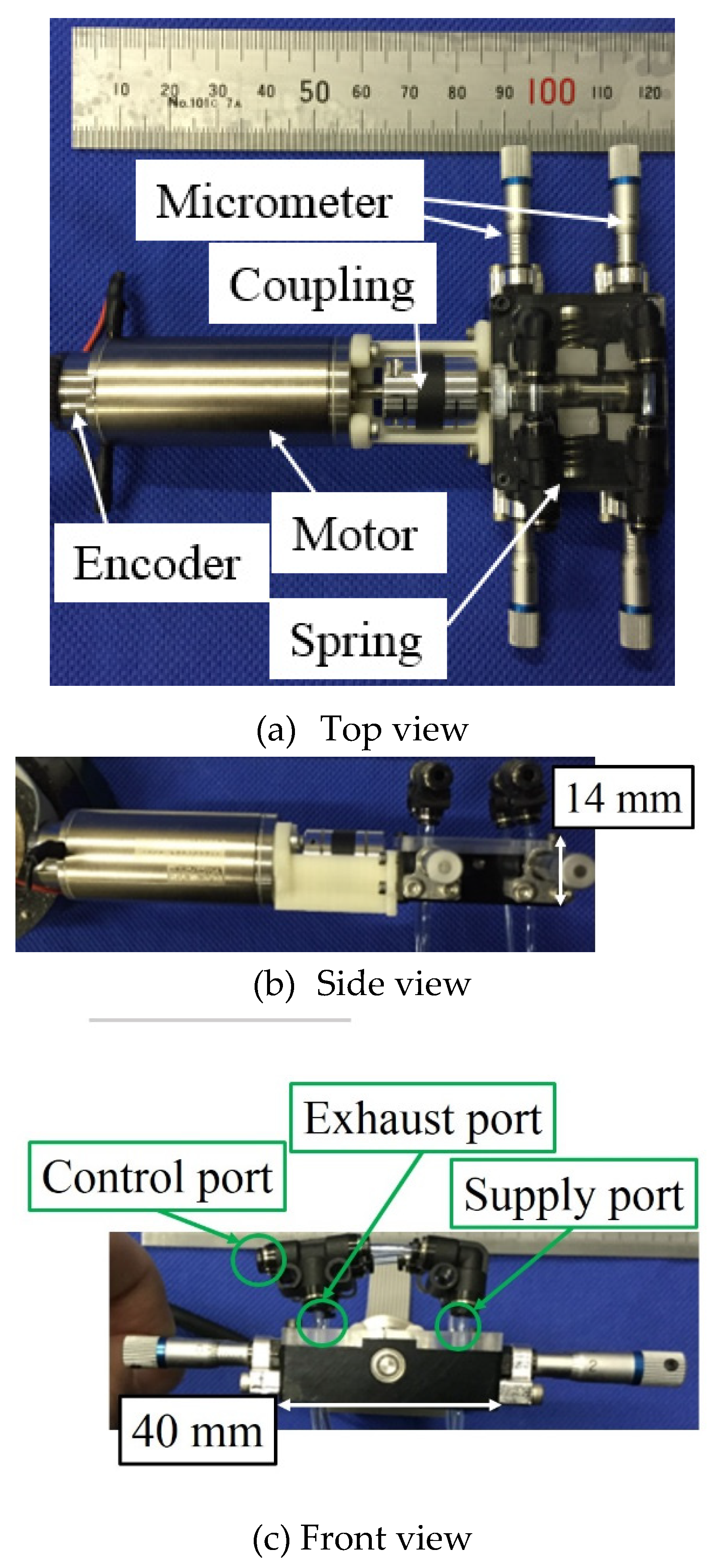
Figure 3 shows the external appearance of the servo valve developed in the study. The developed valve consists of polyurethane tubes for pneumatic piping (UB-1/8-B made by PISCO: Inner diameter 1.0 mm, outer diameter 1.8 mm), a servomotor (DCX22S GB KL 12 V 14 W made by MAXON), an encoder (ENX16 EASY: 1024 Pulse made by MAXON), a cam mechanism part for blocking the tube, and a resin jig for holding the motor and mechanical section. Generally, polyurethane, nylon, and fluororesin tubes are used as pneumatic tubes. Here, polyurethane tubes are softer than tubes composed of other materials and can deform under low forces. Additionally, they also exhibit a small compression set, and thus, they ensure that flow rate characteristics do not easily change with time. Therefore, we selected polyurethane tubes.
Figure 4 shows a model of pinch structure based on cam mechanism. The cam follower is displaced horizontally based on the rotation angle of the cam, and the flow rate is controlled by changing the blocking amount of the tube. Based on the direction of rotation, it controls the flow rate of either the supply or the exhaust.
The position of the adjusting plates on the opposite side of the cam follower in
Figure 4 are adjusted by the micrometers as shown in
Figure 3, and the initial blockage amount is adjusted. The cam in
Figure 4 is connected with the cam in
Figure 5 that shows a model diagram. They are along the same axis and in the same orientation. The cam in
Figure 5 consists of an elliptical cam and springs on the left and right sides. Additionally, in neutral position, the major axis of ellipse is vertical. When the cam rotates, the two springs are compressed, and the restoring force of the spring causes a force in the direction in which the cam returns to the neutral position, thereby achieving normal closing.
Figure 6 shows an example of the piping connection.
Figure 7 shows the overall structure of the mechanism section. To obtain four ways, the developed valve includes two cams shaped as
Figure 8 for flow rate control and a cam for normal closing on the same axis on the camshaft. The two cams for controlling the flow rate exhibit the same shape and are arranged in the positions that are misaligned by 180 degrees (arrangement inverted upside down in
Figure 7). Thus, the supply and exhaust ports are arranged on the same side, respectively to facilitate a piping connection when we use multiple valves. Additionally, the camshaft is connected to the rotating shaft of the motor by coupling without passing through the speed reducer. The range of movement of the cam rotation angle during driving of the servo valve is set to ±80 degrees from the neutral position. Moreover, we used narrow blocks for the pinch tube. These blocks are shown as green parts in
Figure 7 and made from aluminum. The thickness is 1 mm, width is 7 mm, and height is 3 mm.
Figure 8 shows the shape of the cam. This cam was made by wire electric discharge machining that has a
m fabrication precision. ‘a’ and ‘b’ are exaggerated for illustrative effects and the dashed line means a circle with 4 mm radius. The shape of the cam is bilaterally symmetrical. The distance
r from the rotation center of the cam surface is expressed by the equation shown in the figure. As shown on the lower side of the cam in the figure,
is lower than the perfect circle shown by the dashed line. The blocking of the tube is loosened from the neutral state, and the degree of opening is adjusted by the amount of loosening. From a controllability viewpoint, it is preferable for the cam rotation angle and effective sectional area to exhibit a linear relationship. With respect to cams shown in
Figure 9 that are fabricated as preliminary prototypes, the relationship between the rotation angle of the cam and effective cross section corresponds to a nonlinear U-shaped curve as shown in
Figure 10. We think this is because we used a quadratic curve in the relationship between cam angle and radius. The differential value of quadratic curve is small; therefore, the change of effective area can be blunt near 0 degrees. This leads to slow response around neutral position. Then, we tried to make the change of effective area bigger around 0 degrees. To achieve this aim, the radius of the cam was required to change rapidly. Therefore, in the valve developed in this study, the part where the cam radius is proportional to the cam angle is set such that the rate of change of
with respect to the angle increases near 0 degrees. The equations that represent the relationship between cam angle and radius are divided where theta equals 45 and 90 degrees as shown in
Figure 8. The upper side of the cam corresponds to a part to maintain the blocked state. However, to reliably shut off the flow, the blockage is strengthened by making
larger than the circle. Additionally, at the boundary angle of each curve,
is differentiated with respect to the angle such that the Jacobian of the pressing amount of the tube with respect to the rotation angle of the cam becomes continuous.
3. Flow Rate Characteristics of the Valve
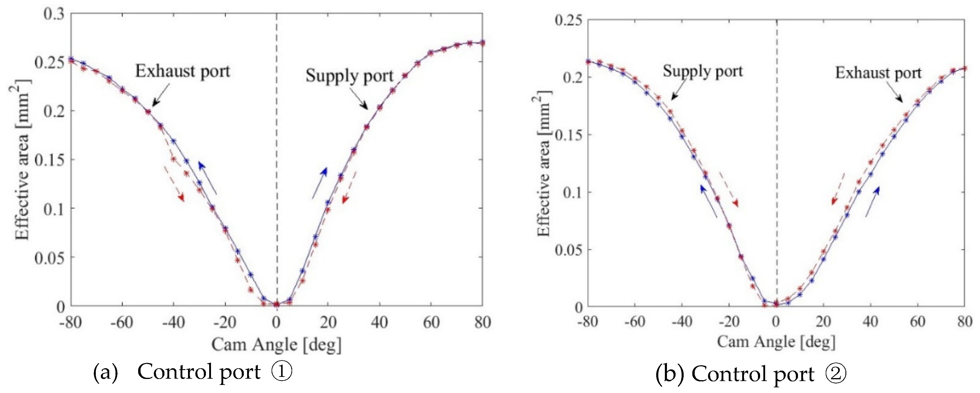
To evaluate the flow rate characteristics of the servo valve, the relationship of the effective cross-sectional area with respect to the cam rotation angle is measured. The effective cross-sectional area was obtained from the flow rate measured by a method using an isothermal chamber [
15]. The measurement was performed by changing the cam rotation angle in increments of 5 degrees.
Figure 11 shows the results of the measurement. A cam angle of 0 degrees corresponds to the neutral position as shown in
Figure 4. It was divided into the supply port and exhaust port with 0 degrees as the border. To verify fluctuation in the flow rate and hysteresis, measurements were conducted thrice in each rotation angle direction. Hence, a total of six rounds of measurements for an angle was performed. Although it was confirmed that the degree of opening saturated at 50 degrees or more and −50 or less. Moreover, we showed flow characteristics of a previous prototype pinch valve [
15] in
Figure 10. By comparison of
Figure 10 and
Figure 11, the developed valve in this study exhibited a V-shaped characteristic compared to a previous prototype pinch valve. When fitting is conducted in range of 0 to 20 degrees, the difference between fitting line and experimental data of the valve developed in this study is revealed as 10% while that of previous prototype is 20%. Additionally, as we proved in [
15], the spool-type valve does not have V-shaped characteristics. It means our newly developed pinch valve does not have a dead zone, which is observed in a previous prototype pinch valve and spool-type valve, around 0 degrees. Additionally, its leakage is much smaller than that of spool-type valve. Hence, this indicated that the zero overlap characteristic of the spool-type valve was realized. This suggested an improvement in the linearity of the characteristics around the neutral position compared to the previous prototype pinch valve. However, it was observed that the flow rate characteristic was asymmetric. Moreover, the graph shapes are not the same between the two graphs, especially at exhaust port. These can cause nonlinearity in the valve, and it is not desirable for the control. These are considered as caused by the cam shape and eccentricity of the camshaft. It is extremely important to ensure that the cam shape is considerably accurate. Hysteresis of the effective area was almost absent in the area where the cam angle was ±40 degrees. However, hysteresis exists in a high flow rate range (and especially −70 degrees or less and 80 degrees or more). For now, it is rare to use a high flow rate to the actuate system. Thus, the hysteresis obtained in the result does not constitute a significant problem.
4. Frequency Response of Cam Angular Control
To investigate the response of the servo valve, we controlled the angle of the cam. The zero point was adjusted, the tube was set to an appropriate closing amount, and the experiment was then performed by applying a supply pressure of 500 kPaG, which is a value that is normally used in our pneumatic servo applications, satisfying the required driving force with the maximum working pressure range. The frequency response was measured as a sine wave signal with amplitudes corresponding to 20 and 40 degrees for the target value of the angle. The target value of the angle corresponded to 25% and 50% with respect to the maximum rotation angle of 80 degrees.
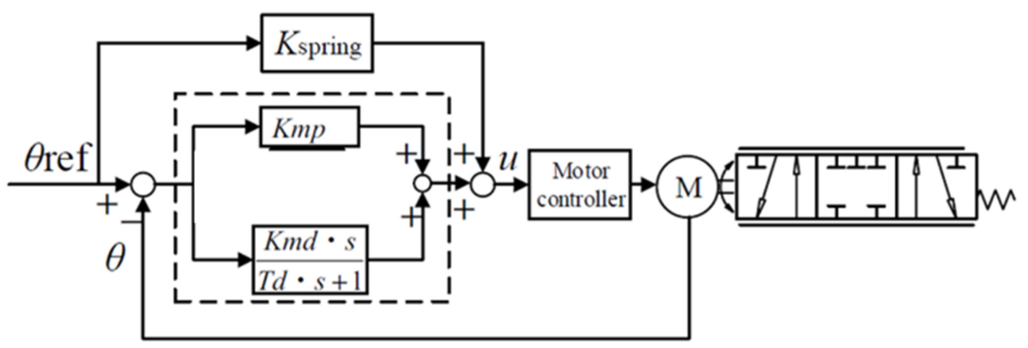
Figure 12 shows the block diagram of the angular control, and
Table 1 shows the control gains. The angular control was performed by adding the feedforward of spring force compensation to the PD control. In the figure,
θ corresponds to the value read by the encoder. The output torque of the motor was proportional to input voltage
u of the motor controller, and the proportionality constant corresponded to 34.8 mNm/V.
Figure 13 shows the Bode diagram in which it is confirmed that the band width is approximately 60 Hz when the angular amplitude corresponds to 20 degrees and 40–50 Hz when it corresponds to 40 degrees. However, the phase lag significantly exceeds 90 degrees, therefore the maximum frequency that the motor can track the target value is 30–40 Hz. Responsiveness depends on the dynamic characteristics of the servo motor. Thus, it was necessary to select a motor with a higher response to improve responsiveness.
5. Position Control of Pneumatic Cylinder by Using the Prototype Valve
Next, we performed the position control experiment of the double acting pneumatic cylinder by the developed servo valve. The supply pressure to the valve was 500 kPaG through the pressure reducing valve.
Figure 14 shows the block diagram of the pneumatic cylinder position control, and
Table 2 shows the respective control gains. The control gains were determined by trial and error. A low-friction pneumatic cylinder (CJ2XB10-30RZ made by SMC) was used, and the area
A1 and
A2 of the pressurized regions corresponded to 78.5 and 66.0 mm
2, respectively. The position of the pneumatic cylinder was measured by a wire type encoder (MLS-12-1500-250 made by MTL), and a PSE540 pressure sensor manufactured by SMC was used. The driving force
F of the pneumatic cylinder was calculated from the pressures
P1 and
P2 of the respective chambers of the pneumatic cylinder and the pressurized areas
A1 and
A2. The driving force
F was fed back. Additionally, friction compensation was added to the target value
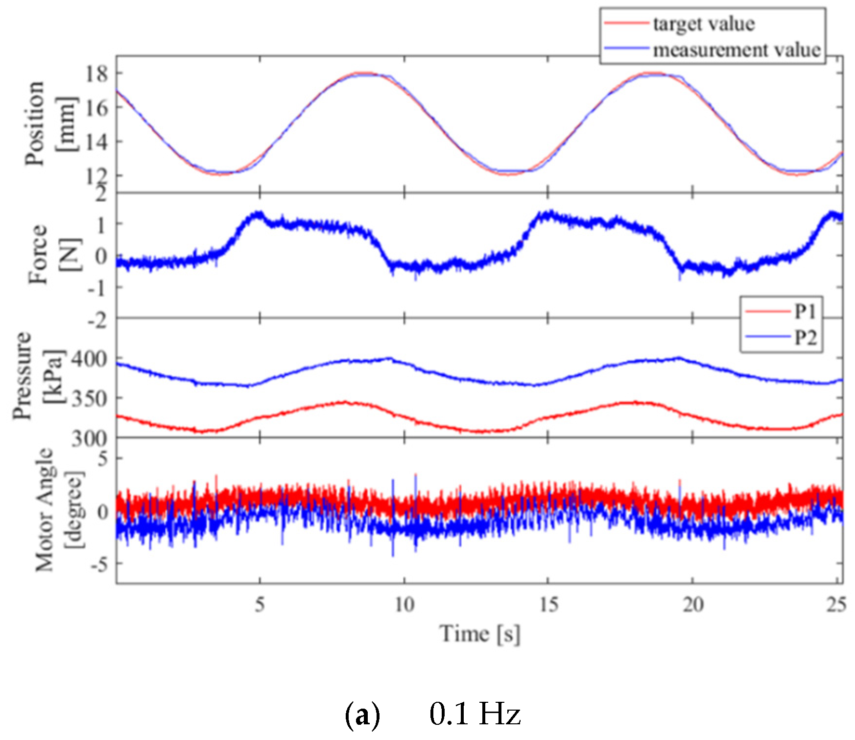
Fref of the driving force as feedforward. We conducted experiments with sinusoidal waves of 0.1 and 1 Hz as the position target values to check whether smooth motion was achieved without a stick-slip.
Figure 15 shows the experimental results. With respect to the position of the pneumatic cylinder, driving force, and motor angle, the blue line indicates the measured values, and the red line indicates the target values. With respect to the pressure, the blue line denotes
P2, and the red line denotes
P1. The driving force of the pneumatic cylinder is well controlled with only 40 ms of delay, even though approximately 3 degrees of motor angle error is seen in
Figure 15. The position tracking performance achieved with the gain of −0.14 dB and the phase delay of 2.5 degrees in 0.1 Hz without a stick-slip phenomenon. When the target value is 1 Hz, the gain is 0.14 dB and the phase delay is 5.3 degrees.
Moreover, the results of position control in the same condition using a conventional spool-type servo valve (FESTO, MPYE-5-M5-010-B) is shown in
Figure 16. The voltage in the figure represents the opening rate that corresponds to motor angle of the developed pinch-type servo valve. When 5 V is applied, the spool is positioned at the neutral position where the valve is supposed to be closed. The position tracking performance using the developed valve shown in
Figure 15 is almost equal or greater when compared to those using the conventional spool valve in
Figure 16. We calculated the tracking error for the result of 0.1 and 1 Hz, respectively. The tracking errors of the developed valve are 2.5% at 0.1 Hz and 1.7% at 1 Hz while those of spool-type valve are 4.2% at 0.1 Hz and 4.0% at 1 Hz. From this, we confirmed that the developed pinch valve works as well as the conventional servo valve to control pneumatic actuator.
6. Durability of the Tube
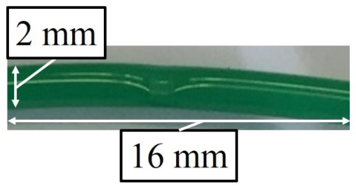
In the pinch value, the tube is frequently and repeatedly deformed, and thus, there are concerns that the tube can deteriorate after prolonged usage. Therefore, we conducted an experiment to investigate the durability of the tube. We used the different cam mentioned above and the cam that has only one flow control cam. Additionally, we conducted the experiment by attaching multiple tubes simultaneously to consider individual differences in elastic tubes. We used a polyurethane tube with an inner diameter corresponding to 1.2 mm and an outer diameter corresponding to 2.0 mm. In the experiment, pressure was not applied on the tube, and the cam was continuously rotated in a direction at a constant speed of 1000 rpm. Moreover, we checked the tube 24 h later and two weeks later, respectively. When we checked 24 h later, deformation marks are observed as shown in
Figure 17. However, we did not observe scratches and cracks.
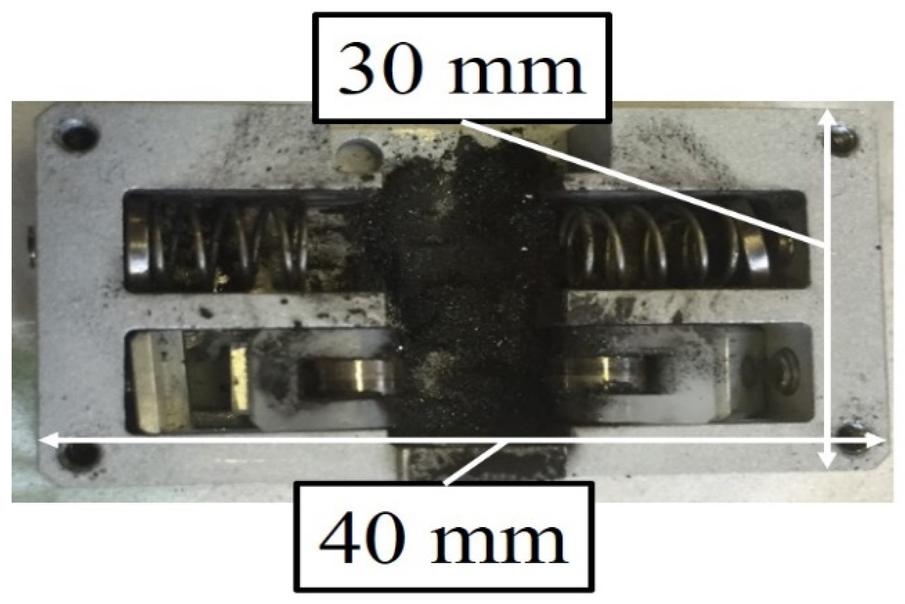
Furthermore, we continued the experiment and checked the tube after two more weeks although there were no further changes in the tube. However, we confirm the significant abrasion of the cam wheel.
Figure 18 shows the inside appearance of the pinch mechanism after durability test. The black powder in the photograph is the product that resulted from abrasion of the cam shaft. Moreover,
Figure 19 shows a worn cam shaft. The surfaces that were touched with the cam follower are scraped and the groove is produced. However, no abrasion was observed on the cam follower.
From the above results, we concluded that the lifetime of cam wheel is dominant when there is no lubrication. Therefore, in the future, we will use grease to prevent abrasion of the cam wheel and investigate about the lifetime of tube and cam wheel.
7. Consumption Flow Rate in the Pneumatic Driving Robot
Finally, the developed valve was applied to the drive of the pneumatically driven robot developed by the authors, and the consumption flow rate in the complete system was evaluated.
Figure 20 shows an overview of the robot used in the experiment. The robot holds the laparoscope in laparoscopic surgery and operates based on the instructions of the operator’s head movement, thereby providing the surgeon with an intuitive field of view operation without using a hand [
16]. It exhibits four degrees of freedom, and each joint is driven by a pneumatic cylinder or a pneumatic oscillating actuator. In the experiment, we conducted the experiment by applying the developed servo valve to three of the joints of the robot (
q1,
q2,
q3 in
Figure 20). We fabricated three identically same pinch-type servo valves and connected them to the pneumatic actuator of each joint as shown in
Figure 21. As the consumption flow rate, we measured the flow rate downstream of the pressure regulating valve before it was distributed to each servo valve. For the flowmeter, we used a Quick Flow Sensor (Tokyo Meter: QFS-50). In the experiment, the sinusoidal wave’s target values corresponding to 0 (stationary), 0.1, 0.2, and 0.4 Hz were simultaneously applied to each joint, and the consumption flow rate is evaluated during the motion. The control system of each joint is shown in
Figure 21.
Figure 22 shows the results of the consumption flow rate measured at each operating frequency as time average values. For comparison purposes, the measurement results in the case when the commercially available spool-type servo valve (FESTO: MPYE-5-M5-010-B) is used are also shown. While it was confirmed that the tracking of motion was almost identical at any frequency, the figure clearly indicates that the consumption flow rate significantly decreases while using the prototype valve. The consumption flow rate decreased by 75% or more at 0.1 Hz and by 35% or more at 0.4 Hz. It was 95% or more in the stationary state at 0 Hz.
In the spool-type servo valve, there was no difference in the consumption flow rate at 0 and 0.1 Hz. It did not depend on the driving speed, and thus, it was confirmed that the leakage flow rate was dominant at the consumption flow rate. Even at a high frequency, the air consumption of the spool-type valve does not increase significantly compared to that of the developed valve. This was potentially because increases in air flows from the supply port to the control ports for the pneumatic cylinder reduced the leak flow rate.
The result indicated that the developed servo valve can contribute to a significant reduction in the consumption flow of the entire system and that wasted air consumption was almost absent and especially in applications with a small movement such as an endoscope operation robot system.
8. Conclusions
In the study, we developed a four-way pinch-type pneumatic servo valve with a closing mechanism by a cam to realize a leakage free servo valve. First, by improvising cam shapes, we realized flow characteristics with high linearity with no dead bands. Second, to confirm its responsiveness, we conducted measurements of the valve’s dynamic characteristics. Thus, when the input signal corresponds to a sine wave with 20- and 40-degree amplitude, responsiveness of approximately 30 Hz was confirmed from the measurement results of the frequency response of the cam angle control. Third, we confirmed excellent position tracking in the pneumatic cylinder position control experiment conducted by using the prototype valve. Furthermore, the endurance test of the tube we conducted indicated that the cam wheel without lubrication wears out before the tube is broken. Finally, we evaluated the consumption flow rate in the robot system and demonstrated that the consumption flow rate significantly decreases and especially at low speed operation.


