Article

Effect of End-Effector Compliance on Collisions in Robotic Teleoperation

Department of Industrial Engineering, University of Padova, 35131 Padova, Italy
*
Author to whom correspondence should be addressed.
Appl. Sci. 2020, 10(24), 9077; https://doi.org/10.3390/app10249077
Submission received: 23 November 2020 / Revised: 15 December 2020 / Accepted: 16 December 2020 / Published: 18 December 2020
(This article belongs to the Special Issue Robotics and Vibration Mechanics)

Abstract

:

Simple Summary

Development of an end-effector able to reduce the momentum transfer from the robot to the object during impacts.

Abstract

In robotic teleoperation, hard impacts between a tool and the manipulated object may impair the success of a task. In order to develop a robotic system that is able to minimize the final velocity of an object after impact, a comprehensive approach is adopted in this work, and the effect on the impact of the parameters of the tool and of the robot is studied. Mass, contact stiffness and damping, robot compliance and control and tool compliance are taken into account. A mathematical model including the tool and the robot moving along the approach direction shows that, in most conditions, robot compliance is not enough to mitigate the impact. A mechanical decoupling between the inertia of the tool and the inertia of the robot is needed. An elastic system based on a bi-stable mechanism is developed and its validity is shown by means of numerical simulations.

1. Introduction

Since its introduction, teleoperation has been extensively studied by control theoreticians with the aim of achieving the goals of stability and telepresence [1,2].
Stability is the ability of a system to remain stable independently of an operator and environment behavior.
Telepresence, also called transparency, is the ability of a system to accurately render the environment to the operator, which means that the position and the force of the slave closely follow the position and the force of the master.
Unfortunately, a delay in the communication channel affects both these goals, and several solutions have been proposed in the past decades to mitigate this problem. As can be inferred from the literature, most of the proposed solutions have focused on the improvement of the control system (wave variables [3], adaptive [4] and model predictive algorithms [5]).
In contrast, in this paper, a completely mechanical approach is adopted. Specifically, the research is focused on improving the use of teleoperation with industrial robots. The aim is to control industrial robots in order to achieve planar movements, such as those needed for smoothing out piles or handling objects.
In this context, the teleoperation is improved by means of an innovative tool design. This tool is able to reduce the transferred momentum to the object during impacts, obtaining a sort of absorption of the impact itself. Consequently, not only are the delay effects reduced, but also the approach velocity can be incremented, allowing faster movements and minimizing task duration. Therefore, the overall quality of the teleoperation can be improved.
It is worth noting that the method used in this paper can be applied to all kinds of system in which a delayed/absorbed impact is targeted. For example, the designed tool can be applied in tasks in which the environment is unknown, and a vision system, which has been extensively used in this context [6], cannot be used or is difficult to implement. In this case, the robot can move blindly in a certain direction, and when an impact occurs, the robot can feel this via sensors on the tool or via the torque sensor of the robot (if present). Thanks to the design of the tool, the robot has enough time to elaborate the signals from the sensors and respond to the impact, without the risk of shooting away the objects.
It is important to underline that the tool requires very small modifications when dealing with objects of different sizes and masses. Accordingly, this study can be considered to correspond to the field of flexible and adaptive tools [6,7,8,9].
In this paper, the planar movement of a tool mounted on a typical six-degree of freedom (DOF) industrial robot with a spherical wrist is considered. A mono-dimensional model of the collision is implemented, which is enough to characterize the movement of the end-effector along the approach direction. Consequently, the six-DOF robot model has been reduced to a a one-DOF mass–spring–damper system, and the effects of the compliance and the inertia of the robot in the impact are taken into account. The properties of the tool are investigated and optimized in order to reduce the momentum transferred during impacts. Finally, a non-linear system is developed, obtaining a tool that, in simulations, is able to delay the moment in which it actively pushes the objects, giving time to the robot and the operator to detect and respond to the impact.

2. Impact between the Tool and the Object

In teleoperation, hard impacts between the tool and the object that has to be manipulated often occur. The impact can be mitigated with a proper design of the tool and by acting on the control system of the robot. Many different situations require the mitigation and control of impact. First, a hard impact may lead to a large final velocity of the object that may separate it from the tool. Eventually, this condition leads to many tool–object impacts that impair teleoperation tasks. The impact force is important, because it may damage the object and the robot. Moreover, the robot control system is usually designed to decelerate a robot when a contact is detected, and the measurement of the impact force is one of the best ways to detect the contact. The duration of the impact is very important as well. If the impact is short in comparison with the typical response time of the robot, the robot has a very short time to decelerate after impact detection. Conversely, if the impact is rather long, the robot has enough time to decelerate and mitigate the impact.

2.1. Instantaneous Impact

If the duration of the impact is very short and the impact force is so large that other forces can be neglected, the impact between the tool of the moving robot and the object can be studied according to the classical impact theory [10]. Two limit cases are represented in Figure 1.
In the first limit case, the tool, which has a plane face, is rigidly connected to the robot, and the object is a spherical point mass. Since the mass of the robot with the tool is much larger than the mass of the object, its velocity change is negligible. In other words, the velocity of the tool after the impact ( V t ) is equal to the velocity before the impact ( v t ) and is imposed by the control system of the robot. The final velocity of the object can be calculated using the restitution coefficient (e), which is the ratio of the relative velocity of the two masses after the impact to that before; e = 1 means that the contact is elastic (no kinetic energy is lost), and e = 0 means that the contact is completely inelastic. The following equation holds:
V p = V t + e ( v t v p )
in which v p and V p are the initial and final velocities of the object, respectively. It is worth noting that the mass of the object has no effect on its final velocity. If the tool is moving with velocity v t = 1 m/s and the object is initially stationary, the final velocity of the object is V p = 2 m/s with e = 1 (pure elastic impact) and V p = 1 m/s with e = 0 (completely inelastic impact).
In the second limit case, the tool is completely decoupled from the robot and is represented by a simple point mass m t with plane faces. The initial velocity v t of the tool is imposed by the motion of the robot, but it can change after the impact and the tool can move backwards. The conservation of momentum of the mechanical system depicted in Figure 1b leads to the following:
m t v t + m p v p = m t V t + m p V p
The final velocities of the two masses can be found by coupling Equation (2) with Equation (1):
V t = v t + m p m t + m p ( 1 + e ) ( v p v t )
V p = v p m t m t + m p ( 1 + e ) ( v p v t )
Figure 2 shows the effect of e on the final velocities. A tool with m t = 0.125 kg and v t = 1 m/s and an object with m p = 0.25 kg and v p = 0 m/s are considered. The increase in the restitution coefficient leads to increases in the final velocity of the object and in the velocity variation of the tool.
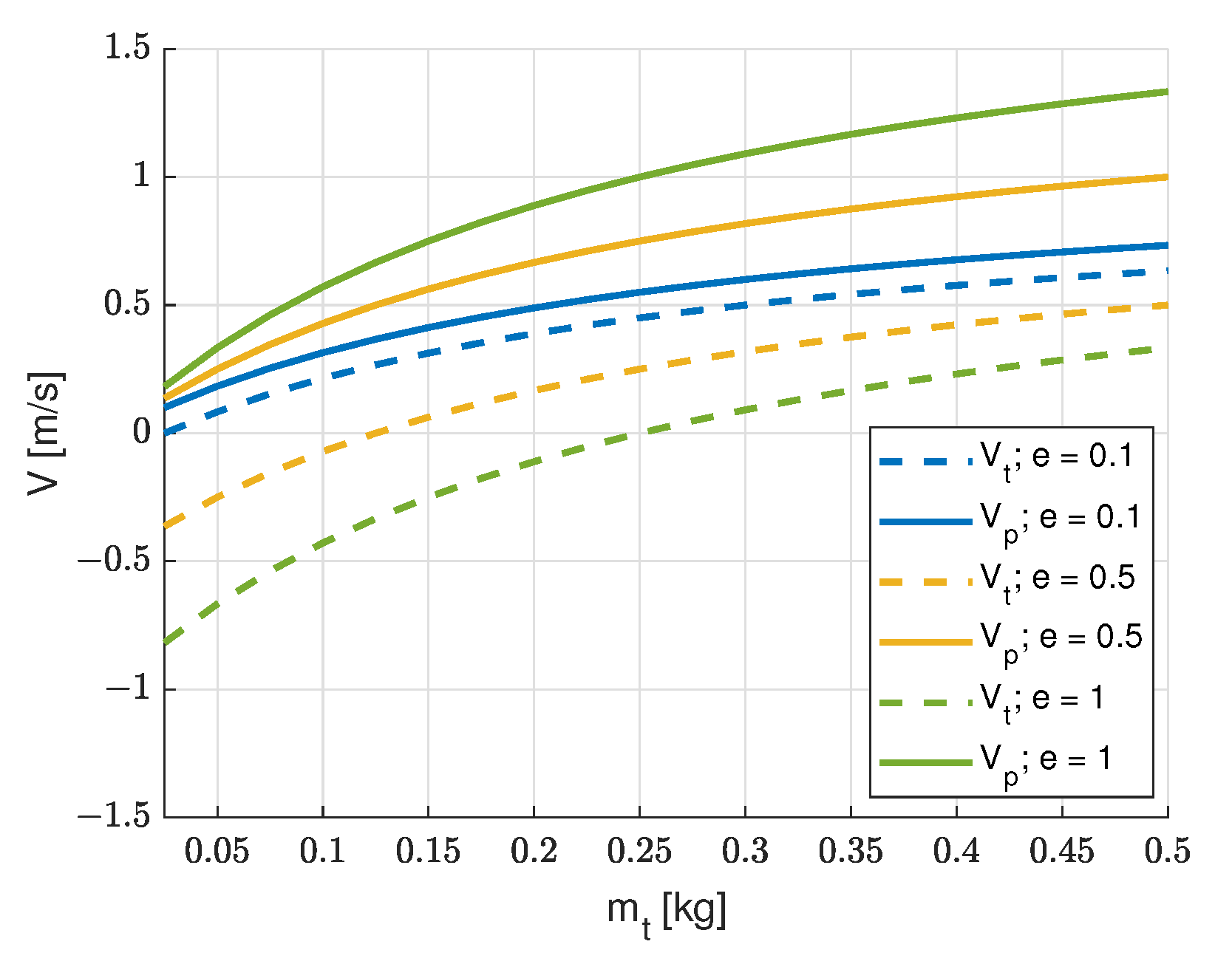
The effect of tool mass is depicted in Figure 3. A decrease in the mass of the tool causes a decrease in the final velocity of the object for every value of the restitution coefficient.
The comparison between the final velocities of the object calculated in the two limit cases shows that the variation in the velocity of the tool leads to a large reduction in the final velocity of the object. In fact, the tool is neither rigidly fixed to a massive and stiff robot nor completely free to move. Nevertheless, this simple analysis shows that the decrease in the restitution coefficient and the mechanical decoupling between the tool and the robot are needed to minimize the object’s final velocity.

2.2. Non-Instantaneous Impact

The theoretical analysis presented in the previous sub-section in many practical cases gives a good prediction of final velocities, but it does not give information about the contact force and duration, which are very important for robot control.
In recent years, many contact force models have been presented [11]. The impact between the two bodies can be schematized as in Figure 4, in which there an elastic element and a damping element in parallel are present.
The elastic element can be linear or non-linear; the damping element is usually non-linear and the damping force depends both on the deformation velocity δ ˙ and on deformation δ . Most of the proposed contact models [11,12,13] can be formulated according to this equation:
F = k c δ m + χ δ n δ ˙
in which k c is stiffness, χ is a constant and m and n are two exponents.
In the present case, F is the force that a tool exerts on the object, and δ = x t x p , with x t x p > 0 to guarantee the contact.
The motion of the two masses after the impact can be calculated by solving the two differential equations:
m t x ¨ t = F m p x ¨ p = F
If the tool is rigidly connected to the robot, only the second equation has to be solved, because x t is assigned. Since in general F is non-linear, a numerical integration was carried out by means of Simulink.
It is worth noting that Equation (5) with m = 1 and n = 0 represents a simple linear spring–damper contact model. The simple linear contact model makes it possible to predict the contact forces and impact duration and leads to a simple relationship between the damping ratio of the relative motion and the coefficient of restitution [10], but it has some drawbacks. The coefficient of restitution does not depend on the relative velocity before the impact (as experimentally assessed [12]). The viscous component of the contact force is discontinuous, since it suddenly increases at the beginning of the contact, is not zero at the end of the contact and is opposed to the separation between the object and the tool. This behavior is not consistent with physical intuition, since at the beginning and at the end of the contact there is no penetration and the force should be zero [12].
A non-linear contact model overcomes most of the above-mentioned limits. In the framework of this research, a contact model with m = 3 2 and n = 3 2 was considered. Since the tool and the object can be schematized as a plane surface and a sphere, respectively [14], the exponent of the elastic force comes from the well-known Hertz contact law [12]. The calculation of the energy lost in the hysteresis loop of the damping force shows that exponent n has to be set equal to m [12]. The damping constant χ is related to the contact stiffness and to the restitution coefficient by this equation, as derived in [15]:
χ = 3 2 ( 1 e ) e k c 1 δ ˙ i n
in which δ ˙ i n is the initial relative velocity. It is worth noting that Equation (7) comes from an improvement of the impact model presented in [12], which extends the validity of the model in the range of small restitution coefficients.
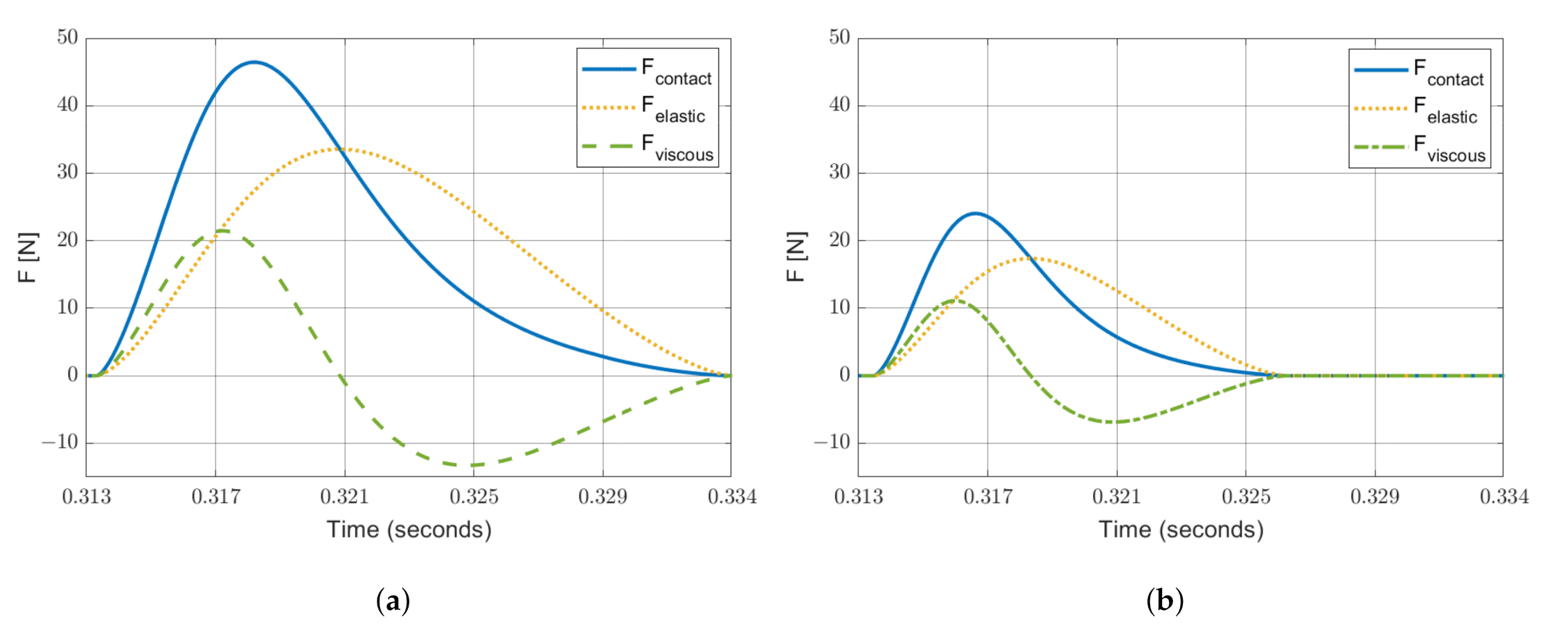
Figure 5 shows the total contact force and its elastic and damping components calculated for the two limit cases of Figure 4. In the simulations, the following parameters were adopted: m t = 0.125 kg, m p = 0.25 kg, k c = 10 5 N m 1.5 , e = 0.5 , v t = 1 m/s and v p = 0 m/s. The non-linear model leads to a realistic shape of the damping force (without discontinuities) and of the contact force. If the tool is rigidly connected to the robot, the contact force peak is almost twice that of the peak that occurs when the tool is decoupled. The duration of the contact decreases if the tool is decoupled from the robot.
Referring to Figure 5a, it is worth noting that the damping component of the contact force becomes negative for t > 0.321 s. This result does not mean the presence of a force that is opposed to the detachment of the two bodies; in fact, even if in Figure 4 the spring and the damper are depicted as two separate lumped elements, they are associated to the deformation of the same body, and a negative damper force only means that damping decreases the contact force with respect to the theoretical value corresponding to a purely elastic contact.
The effects of the contact stiffness k c and of the restitution coefficient e on the contact force and impact duration were analyzed by carrying out series of numerical simulations with m t = 0.125 kg and m p = 0.25 kg. The initial velocities were set to v t = 1 m/s and v p = 0 m/s. The simulations considered both cases, as shown in Figure 4.
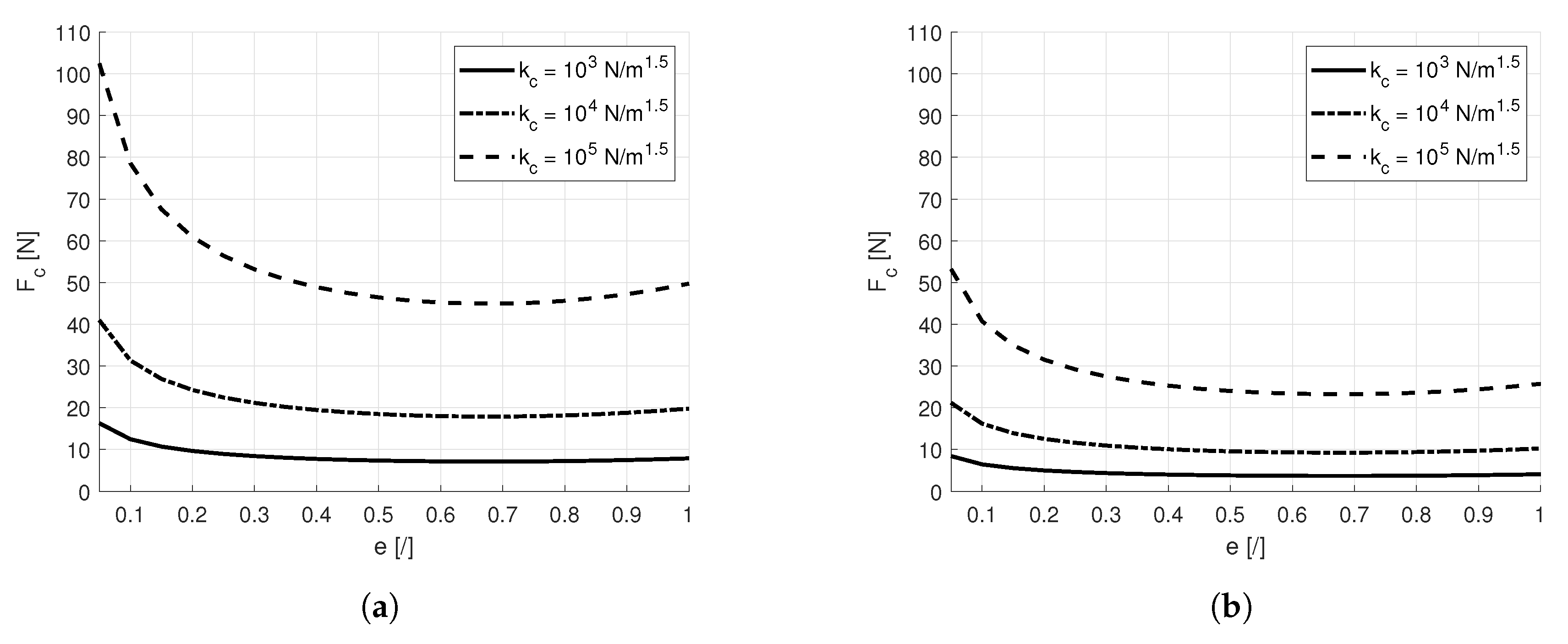
Figure 6 shows that, when e is assigned, an increase in contact stiffness k c leads to an increase in contact force. This behavior is consistent with physical intuition. When k c increases, the deformation decreases, but the elastic energy transferred from the tool to the object has to remain constant, since e is fixed. Thus, the reduction in deformation is compensated by the increase in contact force. If the contact stiffness k c remains constant, the global contact force increases as the restitution coefficient e decreases, owing to the increasing contribution of the damper force.
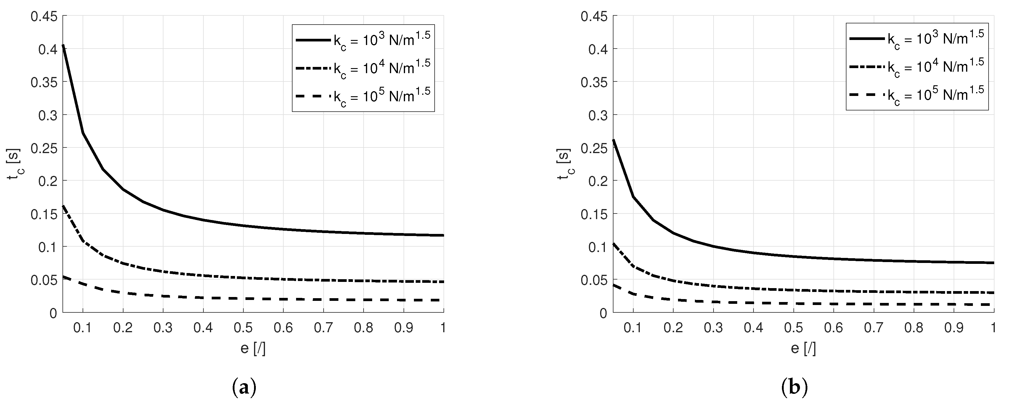
Figure 7 shows that an increase in contact stiffness k c leads to a decrease in the impact duration. This effect takes place because deformation decreases when k c increases. The increase in the impact duration with the decrease in restitution coefficient e is related to the fact that if e tends to zero (inelastic impact), the two masses move together after the impact.

3. Effects of Robot Compliance

In the analysis of the interaction between the tool of the robot and an object, it is important to consider three essential aspects of robot dynamics. Firstly, as the mass of colliding objects dramatically influences the momentum transfer (see Figure 3), it is important to quantify the robot mass involved in the collision. Secondly, since industrial robots are characterized by an intrinsic compliance [16], this feature could be exploited to mitigate the impacts. Finally, the combination of joint elasticity and link inertia induces vibrations in the robot that affect the motion of the tool and the impact velocity. Thus, this section aims to develop a one-DOF robot model that is useful to evaluate the contribution of the inertia and elasticity of a robot along the approach direction during the collision.

3.1. Model of Robot Compliance

The mathematical model of Figure 8 was developed. The slider moves along the approach direction with the motion law imposed by the robot control system (coordinate x r ). It is connected to the motors of the robot by means of ideal transmissions without compliances and clearances. The spring with a stiffness of k r and the damper with a constant of c r represent the compliance and the damping of the robot in the approach direction. A share ( m r ) of the mass of the robot is added to the tool. The friction force between the object and the plane of motion is not taken into account, but it may cause small (and beneficial) reductions in the final velocity of the object.
During the collision, the system is described by the following equations of motion:
( m r + m t ) x ¨ t = c r ( x ˙ r x ˙ t ) + k r ( x r x t ) k c δ m χ δ n δ ˙
m p x ¨ p = k c δ m + χ δ n δ ˙
Equations (8) and (9) hold if δ > 0 .
The main issue is the identification of the robot’s parameters, which appear in this model ( k r , c r , m r ). In this research an Omron Adept Viper s650 is considered. The robot is represented in Figure 9.
It is assumed that robot compliance is due to the compliance of the joints around their rotation axes, while the links and bearings are considered perfectly rigid. With these hypotheses, if the i-th actuator imposes a rotation q i ( t ) on the i-th joint, the actual rotation ϑ i ( t ) of the joint does not coincide with q i ( t ) . In order to consider this behavior, each joint was schematized by means of a spring–damper model, so that the torque produced by the actuator was transmitted to the joint by means of these elements. The motion of a serial six-DOF robot with compliant joints is represented by a system of six second order differential equations:
M q ( q ) ϑ ¨ + C ( q , q ˙ ) + D q ( ϑ ˙ q ˙ ) + K q ( ϑ q ) + G ( q ) = 0
where
  • q is the vector which contains the joint variables imposed by actuators;
  • ϑ is the vector containing actual joint variables;
  • M q ( q ) is the robot mass matrix in the joint space;
  • C ( q , q ˙ ) is the term related to centrifugal and Coriolis forces;
  • D q is the robot viscous damping matrix in the joint space;
  • K q is the robot stiffness matrix in the joint space; and
  • G ( q ) is the term related to gravity forces.
It is possible to neglect centrifugal and Coriolis forces and the effect of gravity when dealing with small oscillations [17]. Therefore, the equations of motion of the robot in the joint space can be simplified as follows:
M q ( q ) ϑ ¨ + D q ( ϑ ˙ q ˙ ) + K q ( ϑ q ) = 0
The mass matrix M q ( q ) can be estimated using the data provided by the computer-aided design (CAD) model of the robot, retrieved from the website of the manufacturer. The matrices D q and K q are diagonal and independent of the robot configuration q . In particular, the terms of these matrices represent the viscous damping coefficient and the stiffness of each joint around its rotation axis, and they can be identified by means of an impulsive modal analysis of the robot [17,18]. The movement of the tool and its collision with an object in the plane of motion are described in the operational space, so it is necessary to transfer the description of robot dynamics from the joint space to the cartesian space. Thus, the mass, stiffness and viscous damping matrices in the cartesian space ( M X , D X , K X ) have to be calculated. The relationships which correlate the matrices in the two spaces [19] are the following:
M X ( q ) = J ( q ) T M q ( q ) J ( q ) 1
D X ( q ) = J ( q ) T D q J ( q ) 1
K X ( q ) = J ( q ) T K q J ( q ) 1
where J ( q ) represents the robot’s Jacobian matrix. It is worth noting that both stiffness and viscous damping matrices ( K X , D X ) are dependent on the robot configuration q . Consequently, it is possible to write the equations of motion in the cartesian space:
M X ( X r ) X ¨ t + D X ( X r ) ( X ˙ t X ˙ r ) + K X ( X r ) ( X t X r ) = 0
In Equation (15), X r is the vector containing the coordinates of the imposed position of the tool in the cartesian space, whereas X t is the vector containing the coordinates related to the actual position of the tool. The robot configuration q is a function of the imposed position X r , obtained through the equations of the inverse kinematics of the robot. Thus, the mass, stiffness and damping matrices can be expressed as functions of X r as in Equation (15).
Equation (15) makes it possible to describe the dynamics of the robot along the imposed tool trajectory. However, it is assumed that the robot control system is able to exactly generate the desired trajectory. In fact, this is not possible in real applications, due to a series of small-entity causes, such as structural imperfections and external disturbances, which introduce small position errors. As already stated, the aim of this model is to estimate the influence of joint compliances and robot inertia properties during a collision, so the hypothesis of perfect control is reasonable.
In the one-DOF model, only the cartesian coordinate that describes the motion of the tool in the direction of approach (x) is considered. Therefore, the equations of motion of the robot are reduced to a single second-order differential equation:
M X , 11 ( x r ) x ¨ t + D X , 11 ( x r ) ( x ˙ t x ˙ r ) + K X , 11 ( x r ) ( x t x r ) = 0
where x r is the x-coordinate imposed by the robot control system, x t is the actual x-coordinate of the tool, and M X , 11 , D X , 11 and K X , 11 are the elements (1,1) of mass, viscous damping and stiffness matrices, respectively.
The mass, damping and stiffness terms of this equation physically represent the lumped element components ( m r , c r , k r respectively), which are added to the impact model represented in Figure 8. Mass M X , 11 = m r simply adds to the tool mass.
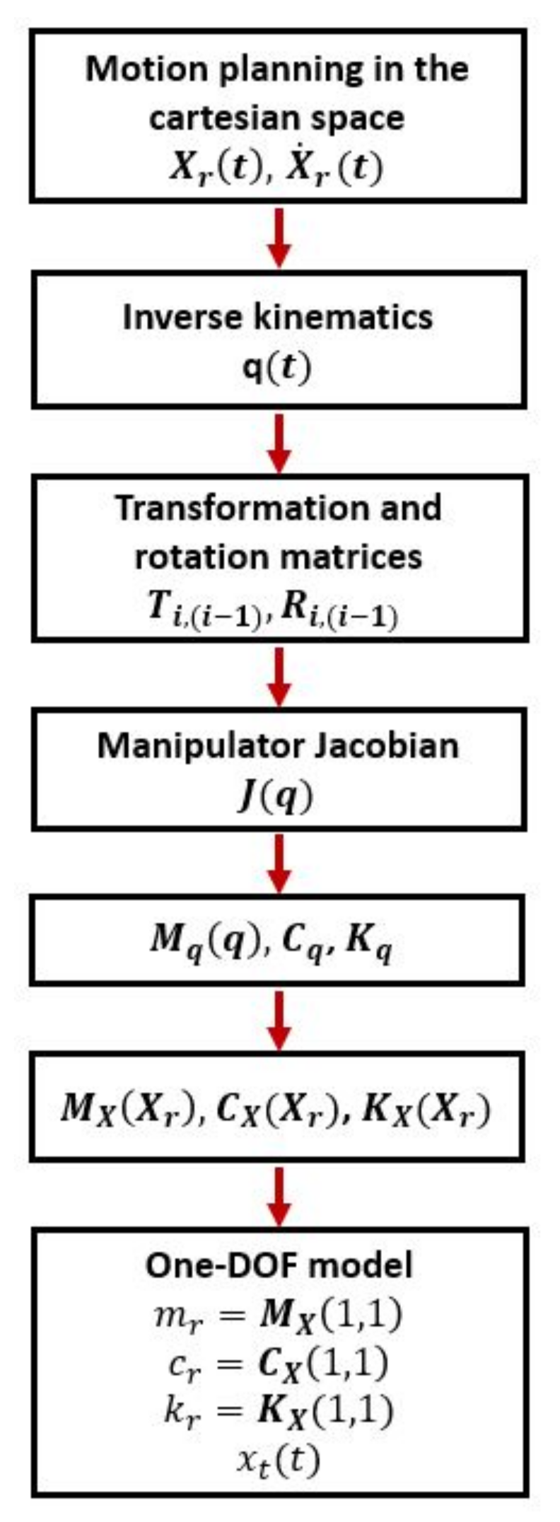
The terms in Equation (16) depend on the robot configuration. For this reason, a MATLAB script was developed to calculate the robot configuration from the current position in the cartesian space and to determine the parameters of the one-DOF model. The script follows the steps reported in the flow chart presented in Figure 10.

3.2. Numerical Results

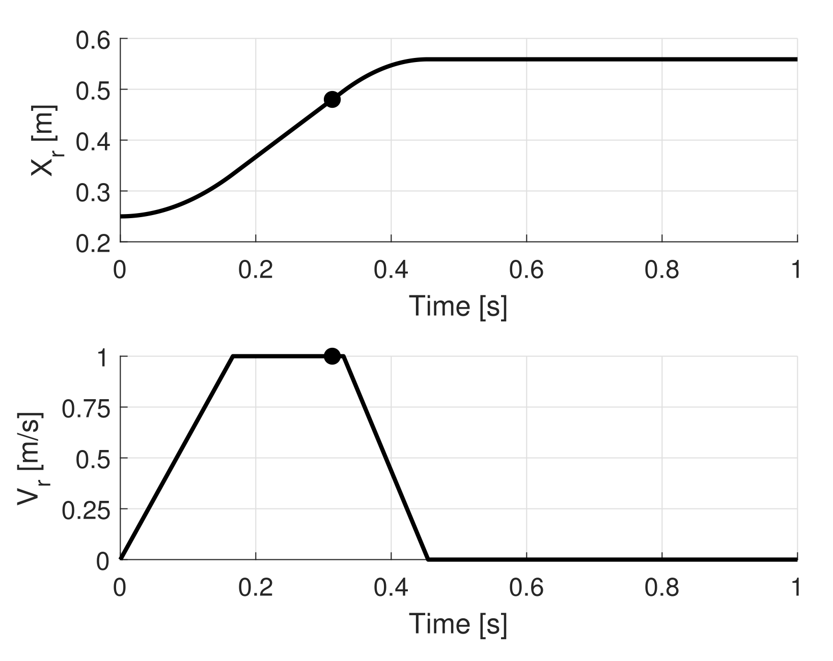
In the simulations, the tool approached an object along a linear trajectory. Moreover, it was assumed that the tool moved between the starting and final point following a trapezoidal velocity profile, and a collision occurred when the robot moved at a constant velocity. The position and velocity are referred to the fixed reference frame of the first joint of the robot (see Figure 9). Figure 11 represents the imposed position ( x r ) and the imposed velocity ( v r = x ˙ r ) of the robot flange before the collision. In order to evaluate the behavior of the robot during the interaction with an object, the robot was assumed to be equipped with a control system that was capable of detecting the contact force and ordering the robot to start braking. The force detection threshold was set to 1 N. The reaction to the impact was not instantaneous, but it was assumed that the robot began to perform braking after 16 ms in order to take into account the delay in processing the external input signal [20]. The circular marker (Figure 11) indicates when the impact happens.
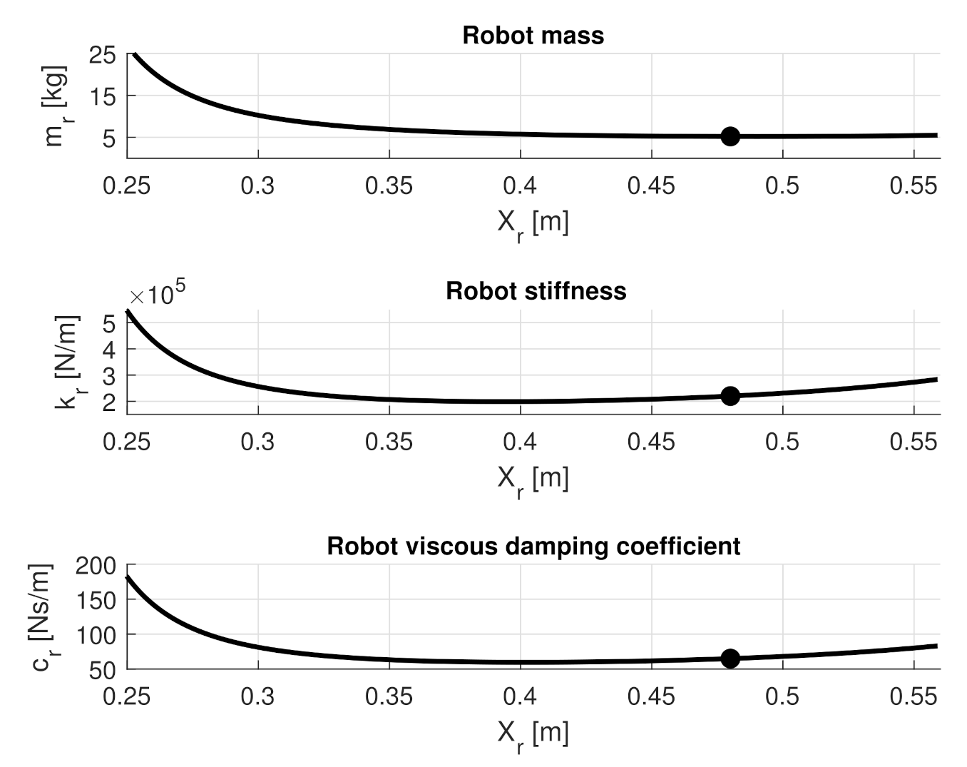
The trends of the lumped element parameters of the robot m r , c r , k r as functions of the imposed position x r are depicted in Figure 12. The circular marker highlights the values of these parameters when the impact occurs.
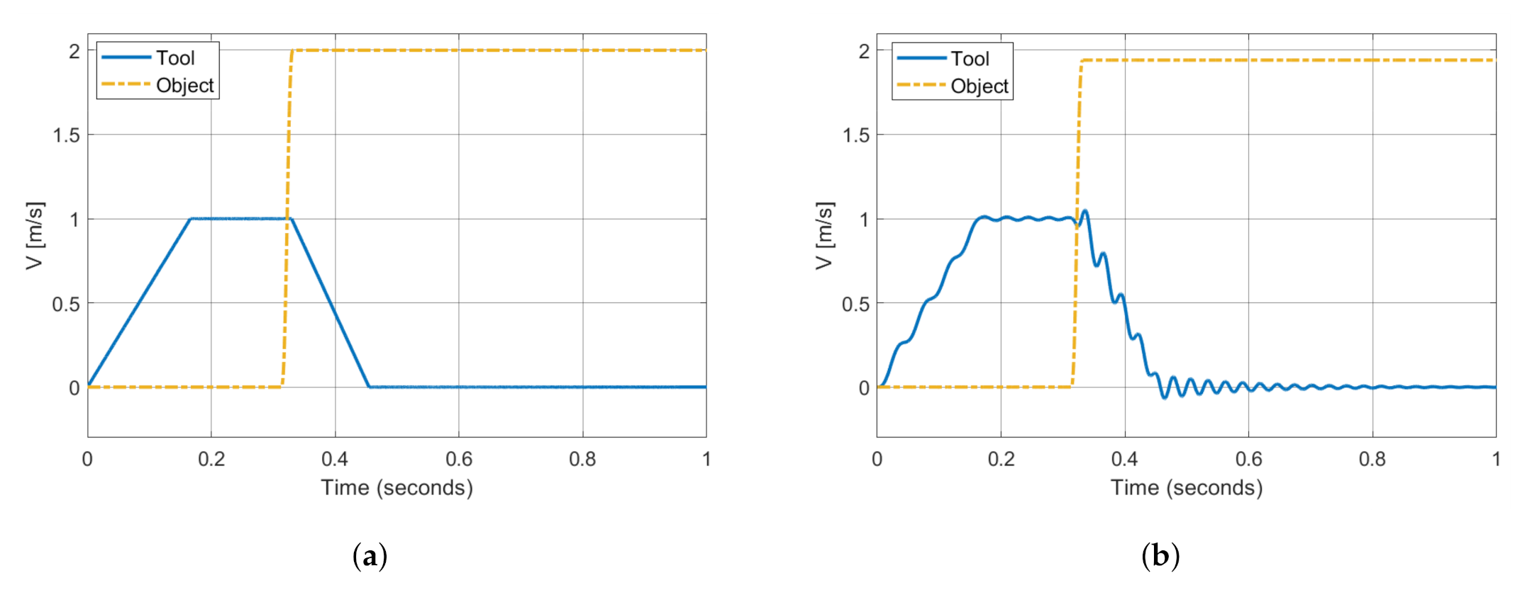
Several scenarios were simulated, with the aim of evaluating the effects of robot properties during the collision. The simulation results depicted in Figure 13a,b represent the velocities of the tool and of the object when the robot had rigid and compliant joints, respectively. A perfectly elastic collision was considered ( e = 1 ) with k c = 10 5 N m 1.5 ; the masses of the tool and of the object were m t = 0.125 kg and m p = 0.25 kg, respectively.
In Figure 13a, the object velocity is exactly twice the approach velocity of the robot and the collision is so short that the robot actuators start braking after the impact. In this condition, as the impact occurred in a period of time in which the mass ( m r + m t ) maintained the same velocity, the robot with rigid joints was equivalent to a slider moving at constant velocity. The final velocity of the object confirmed this assumption (see Section 2.1).
In the case of compliant joints (Figure 13b), the impact velocity is about 0.98 m/s due to the vibrations of the tool (the impact takes place when there is a local minimum of robot velocity), and the velocity of the object is about 1.94 m/s, which is almost twice the approach velocity of the robot. Although the total colliding mass of the robot ( m r + m t ) is not rigidly coupled with the imposed motion, due to the compliances represented by the elements k r and c r of the model in Figure 8, the actual behavior is nearly the same as the robot with rigid joints. Two factors explain these results: firstly, the colliding masses are very different, since the term ( m r + m t ) is equal to 5.35 kg just before the impact, and Equation (4) shows that object velocity increases asymptotically towards the limit case, when the tool mass becomes large; secondly, since the contact force is small, joint compliances have a small influence.
In Figure 14a, a heavy object with a mass of 2.5 kg is considered. This mass roughly corresponds to the rated payload of the robot and is about 48% of the term ( m r + m t ) , which is equal to 5.35 kg just before the impact. The contact stiffness is set to k c = 10 5 N m 1.5 . In Figure 14b the impact against a heavy object ( m p = 2.5 kg) is still simulated, but the contact stiffness is set to k c = 10 6 N m 1.5 . The collision is perfectly elastic ( e = 1 ) in both cases.
With k c = 10 5 N m 1.5 , the final velocity of the object is about 1.88 m/s; this value is very close to that in Figure 13b, despite the difference in the masses of the objects. The impact velocity is about 0.95 m/s, due to a small deformation of the robot and to the vibration of the tool. Although the momentum transferred to the robot is not negligible, the contact force is not able to significantly deflect the robot arm; therefore, the robot is perceived by the tool as a slider moving with constant velocity.
The effect of the robot compliance is more relevant when the object is heavy and the contact stiffness is large ( k c = 10 6 N m 1.5 ), which is the case depicted in Figure 14b. These conditions lead to a larger contact force that is able to deflect the joints of the robot. The comparison between Figure 14a,b shows that in the second scenario, the tool is subjected to a significant deceleration during the impact, which means that the robot has been deformed. The deformation implies that a portion of the mechanical energy involved in the collision is stored as elastic energy inside the joints, and this phenomenon generates an increment in the amplitude of vibrations of the tool, whereas the velocity of the object decreases with respect to the previous cases. However, the elastic response is so quick, due to the high stiffness, that the restitution of part of the stored elastic energy occurs during the collision and the object is pushed away.
These results highlight that in most cases, the robot is perceived by the object as a slider moving with an imposed motion. In conclusion, joint compliances cannot significantly reduce the velocity of the object.

4. Effects of Tool Compliance

Section 3 shows that the inherent elastic and inertial properties of the robot have a small effect on the momentum transfer between the tool and the object. Therefore, in order to compensate for the small compliance of the robot, it is necessary to decouple the tool from the robot. The decoupling system and its effect on the final velocity of the object are discussed in this section.

4.1. Model of Tool Compliance

If robot compliance is negligible, the model that describes the collision comprises the rigid robot, the decoupling elements and the tool (see Figure 15).
The corresponding equations of motion during the collision are as follows:
m t x ¨ t = c t ( x ˙ c x ˙ t ) + k t ( x c x t ) k c δ m χ δ n δ ˙
m p x ¨ p = k c δ m + χ δ n δ ˙
The rigid body moving with imposed motion is the robot flange. The parameters k t and c t represent the stiffness and damping characteristics of the system that decouple the tool from the robot. The set of the decoupling system and the tool represents the end-effector. It is worth noting that the mass–spring–damper system that represents the end-effector is excited by the imposed motion x c , which represents the x-coordinate of the robot flange.
If the two equations are summed, the impact force disappears:
m t x ¨ t + m p x ¨ p = c t ( x ˙ c x ˙ t ) + k t ( x c x t )
If Equation (19) is integrated between the instant ( t 1 ), in which the contact between the tool and the object begins, and the instant ( t 2 ), in which the contact ends, the following result is obtained:
m t V t + m p V p = m t v t + m p v p + c t t 1 t 2 ( x ˙ c x ˙ t ) d t + k t t 1 t 2 ( x c x t ) d t
Equation (20) shows that the linear momentum of the system is no longer conserved owing to the effect of the impulses of the damping and elastic forces. It is worth noting that the elastic and damping forces increase the final momentum as long as the terms in the integrals are positive. The total impulse generated by the decoupling elements is
I = c t t 1 t 2 ( x ˙ c x ˙ t ) d t + k t t 1 t 2 ( x c x t ) d t
Introducing Equations (1) and (21) into Equation (20) leads to the following equation:
V p = v p m t m t + m p ( 1 + e ) ( v p v t ) + I m t + m p
Equation (22) highlights that the total impulse generated by the decoupling system increases the final velocity of the object.

4.2. Simulated Results

The effects of the stiffness and damping of the decoupling system on impact mechanics were analyzed by carrying out parametric simulations with m t = 0.125 kg, m p = 0.25 kg, v t = 1 m/s and v p = 0 m/s. The robot was assumed to start braking after the collision.
The damping coefficient was defined by means of the viscous damping ratio [21] ζ = c t 2 k t m t .
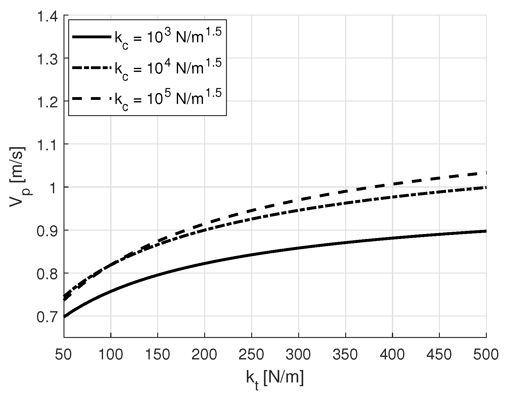
Figure 16 represents the final velocity of the object for different values of contact stiffness k c , as a function of the stiffness k t and considering a constant damping ratio, which is equal to the critical value ζ = 1 . A perfect elastic impact ( e = 1 ) is assumed.
The comparison between Figure 13a and Figure 16, shows that the decoupling system leads to a significant reduction in the velocity of the object after the collision. The increase in stiffness k t and in damping c t of the decoupling system increases the final velocity of the object, in agreement with Equations (20) and (22). Moreover, Figure 16 shows that an increase in k c leads to a decrease in the final velocity of the object. This phenomenon is related to the fact that an increase in k c produces an increase in the contact force which, in turn, generates a large compression of the decoupling system, which moves backwards. Since e = 1 , the relative velocity V r e l before and after the impact are equal and, when there is a backwards motion of the tool, the absolute final velocity of the object V p = V t + V r e l is reduced.
When k t is about 90 N m , the curve corresponding to the largest contact stiffness suddenly changes its slope. After the collision, the elastic energy stored inside the spring of the decoupling system is released and the tool is subjected to a rebound. If the impact duration is short, the restitution of the elastic energy starts very quickly. In this condition, multiple impacts can occur. Therefore, the sudden increment in slope highlights the presence of multiple collisions, which leads to an increment in the final velocity.
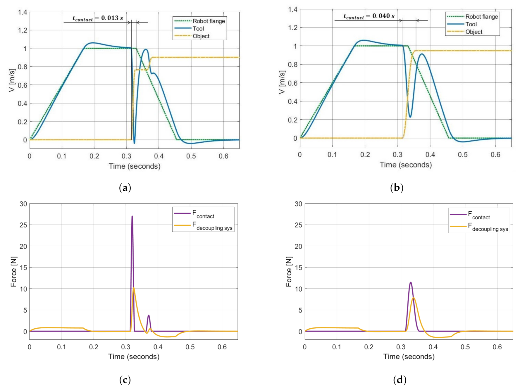
Figure 17a,b represents the robot, tool and object velocities with k t = 150 N m , ζ = 1 , e = 1 . In Figure 17a, the contact stiffness is set to k c = 10 5 N m 1.5 , whereas in Figure 17b, the contact stiffness is set to k c = 10 4 N m 1.5 . The contact force applied to the object and the force generated by the decoupling system on the tool are depicted in Figure 17c,d, respectively.
The end-effector is compressed by the inertia force during the acceleration of the robot. Therefore, the velocity of the tool is slightly higher than the robot velocity when the latter moves at a constant velocity due to the restitution of the elastic energy absorbed during the acceleration. The increase in contact stiffness increases the deceleration of the tool. Figure 17c highlights two clear peaks in the contact force profile and confirms the presence of multiple impacts.
When inelastic impacts are considered, the results show that the final velocity of the object decreases (see Figure 2). Furthermore, the decrease in contact stiffness k c leads to a reduction in the final velocity of the object; this behavior is opposite to that found with e = 1 . Parametric simulations were carried out to analyze this aspect considering m t = 0.125 kg, m p = 0.25 kg, v t = 1 m/s and v p = 0 m/s. The robot was assumed to start braking after the collision.
Figure 18 represents the final velocity of the object for different values of contact stiffness k c as a function of the stiffness k t considering a constant damping ratio equal to the critical value ( ζ = 1 ) . A nearly completely inelastic impact ( e = 0.1 ) was simulated.
The comparison between Figure 16 and Figure 18 highlights that the reduction in the coefficient of restitution inverts the effect of the contact stiffness. A coefficient of restitution near to zero means that the tool and the object move almost synchronously after the collision, because the final relative velocity is only a small fraction of the initial relative velocity. There are two contributions to the final velocity of the object: the momentum transferred during the collision and the momentum transferred during the transient after the impact, when the robot brakes.
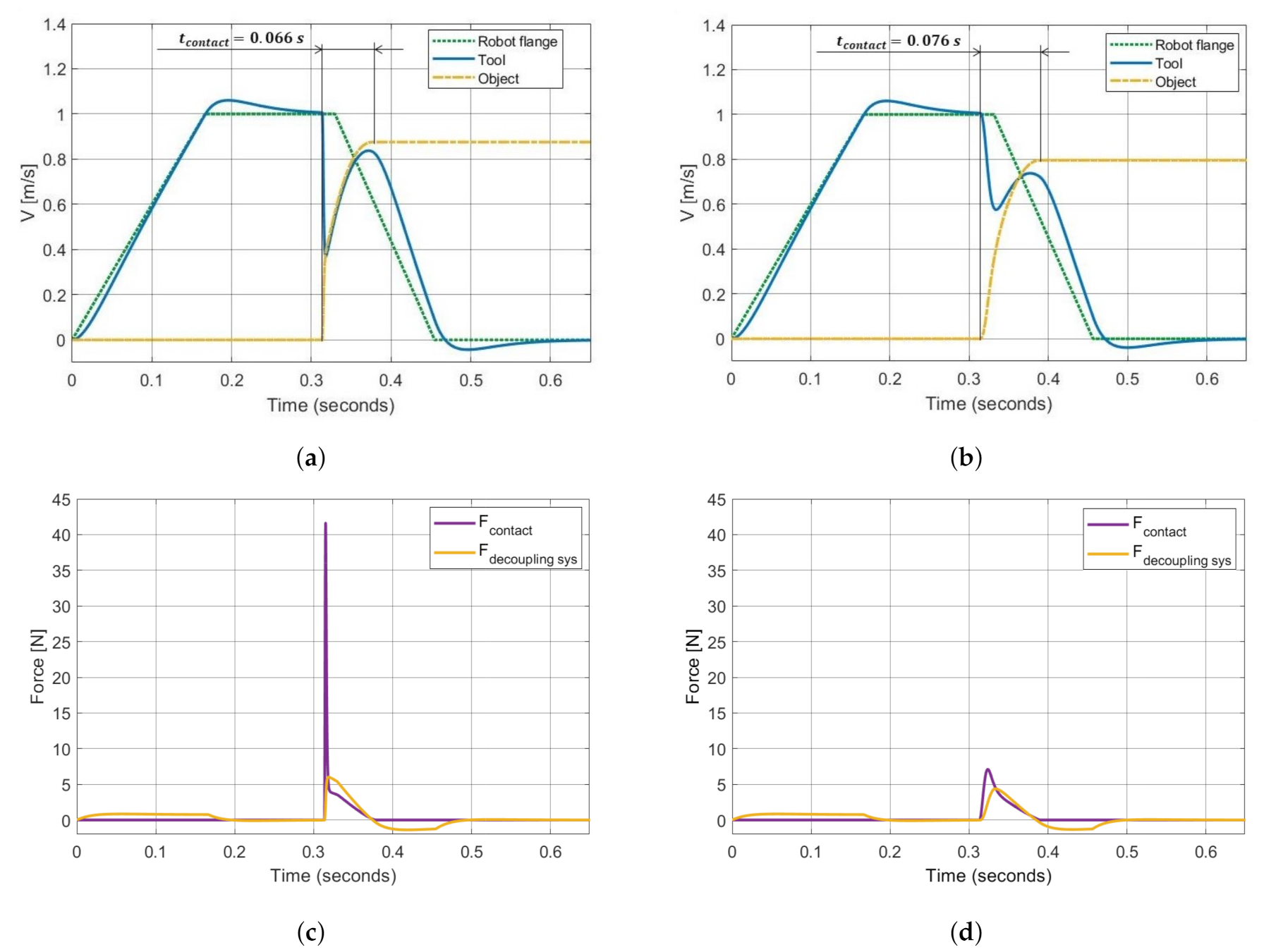
Figure 19a,b represent the velocities of the robot, tool and object. Figure 19c,d shows the contact force and the total force generated on the tool by the decoupling elements. All simulations were carried out with k t = 150 N m , ζ = 1 , e = 0.1 . The contact stiffness was set to k c = 10 5 N m 1.5 in Figure 19a,c and to k c = 10 3 N m 1.5 in Figure 19b,d, respectively.
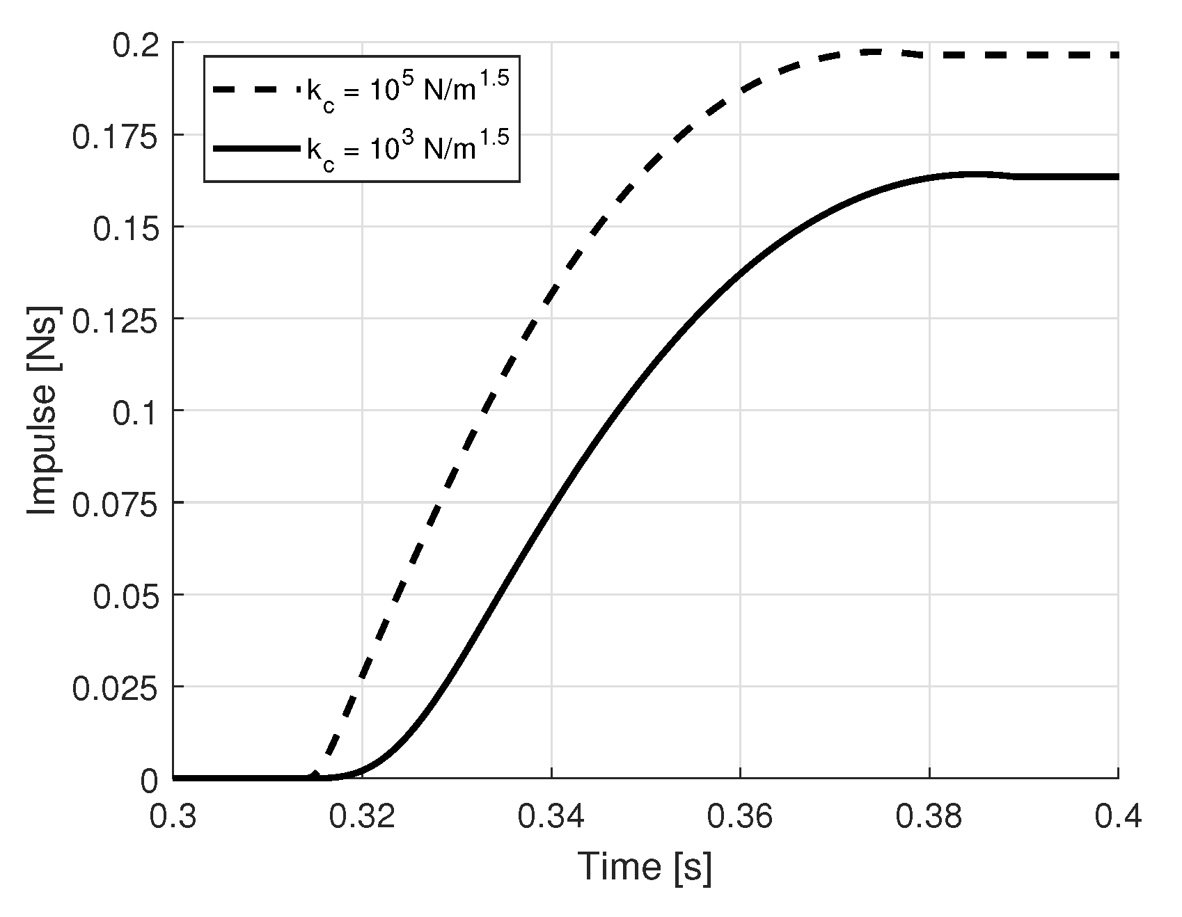
Furthermore, in this case, the increase in contact stiffness increases the deceleration of the tool. When the contact stiffness is low (Figure 19b), even if the deceleration of the tool is reduced, the duration of the total momentum transfer is made longer, and the robot is therefore able to markedly reduce its velocity during the contact between the tool and the object. An inelastic impact makes the dynamics of the object strictly dependent on the robot control system. Thus, the robot control system can be exploited to reduce the final velocity of the object. Figure 19c,d shows that the total force applied on the tool by the decoupling elements is positive during the contact with the object, since the decoupling system is compressed and the velocity of the tool is lower than the robot velocity. Figure 20 compares the total impulse generated by the decoupling system during the contact in the two cases analyzed in Figure 19.
It is worth noting that the larger impulse corresponds to a larger final velocity of the object, in agreement with Equation (22).
Since the impulse generated is equal to the integral of the force applied during the contact time between the tool and the object, the force profile generated by the end-effector during the contact represents a key factor in the optimization of the decoupling system.

5. End-Effector Design

In order to optimize the the force profile generated by the decoupling system, non-linear solutions were analyzed to meet the following requirements:
  • The system has to be able to exert a minimum force on the tool to keep it in the desired position during the acceleration of the robot;
  • The system has to prevent rebounds of the tool in order to avoid multiple collisions and the restitution of the energy absorbed in the impact;
  • The impulse transmitted to the object should be as small as possible, according to Equation (22).
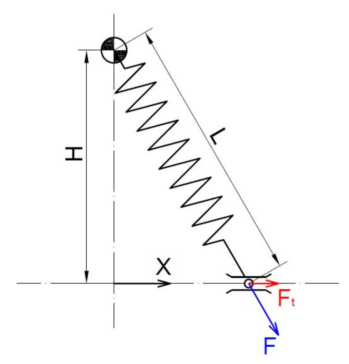
The bi-stable mechanism shown in Figure 21 is considered.
This system is characterized by two stable equilibrium positions and, in general, consists of a spring connected to a sliding element, which is constrained to move along the x-axis. The spring generates an elastic force on the sliding element which has two components: the first is parallel to the x-axis ( F T ) and influences the dynamics of the slider; the second is orthogonal to the sliding path and does not have important effects on the movement of the slider. The component F T generated by the spring is given by the following equations:
F T = k ( L 0 L ) x L
L = H 2 + x 2
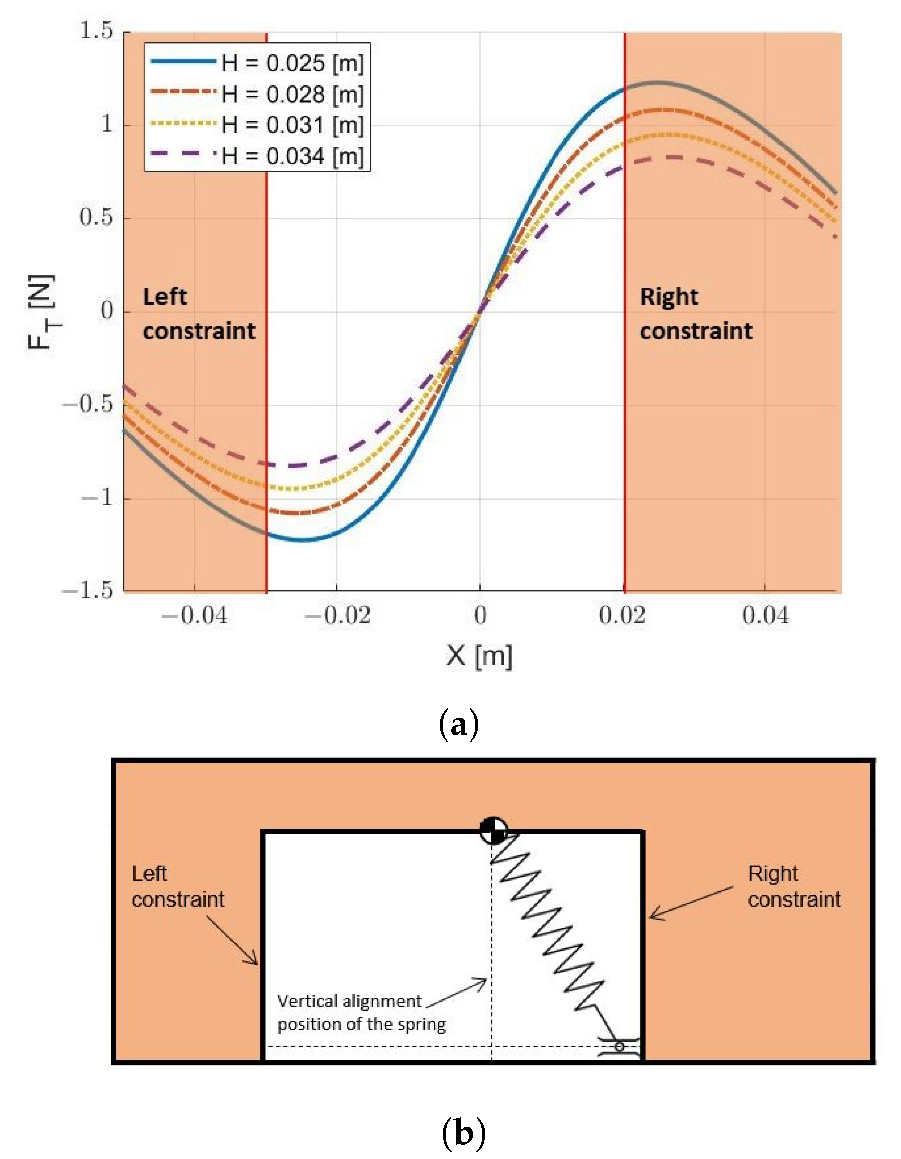
where k is the stiffness of the spring, L is its actual length, L 0 is the spring free length, x is the position of the slider relative to the vertical alignment position of the spring and H is the distance between the upper revolute joint of the spring and the sliding direction. In real applications, the slider could be constrained to move between two mechanical constraints that introduce a limit to its movement [22,23]. The trends of the elastic force F T as a function of the distance from the vertical alignment position are reported in Figure 22a in the case with L 0 = 0.07 m and k = 50 N m . In the same figure, the effect on the force profiles of two mechanical constraints are schematized through the two orange areas, which identify the off-limit zones. The scheme depicted in Figure 22b shows a physical representation of the mechanical constraints.
Figure 22a shows for x > 0 that the force is positive, whereas for x < 0 , the force is negative. The limitation of the movement of the slider between the two mechanical constraints leads to a system that is characterized by a specific portion of the force profile. If the tool is leaning against the constraint placed on the right of the x = 0 position and an external force pushes it back towards the negative direction of the x-axis, the system reacts with a positive elastic force that tends to counterbalance the external force. However, when the vertical alignment position of the spring is crossed, the tool is pulled back against the left constraint and is kept there by the elastic force. The figure shows that it is possible to adjust the maximum positive and negative values of the force profiles modifying the geometrical parameter H, but also to vary the vertical alignment position of the spring in relation to the mechanical constraints. The maximum positive value of the elastic force should be large enough to keep the tool in position against the right constraint before the impact, in order to avoid oscillations, but, at the same time, it should be as small as possible to minimize the impulse transmitted to the object. The maximum negative value of the elastic force should be large enough to pull the tool back and keep it against the robot flange (left constraint).
This bi-stable mechanism was integrated in the numerical model of the end-effector, and a force profile corresponding to H = 0.028 m was implemented. In order to simulate the contact between the slider of the tool and the mechanical constraints of the bi-stable mechanism (see Figure 22b), each constraint was modeled by means of a linear contact model based on a spring–damper system. A completely inelastic impact of the slider against the constraints was assumed.
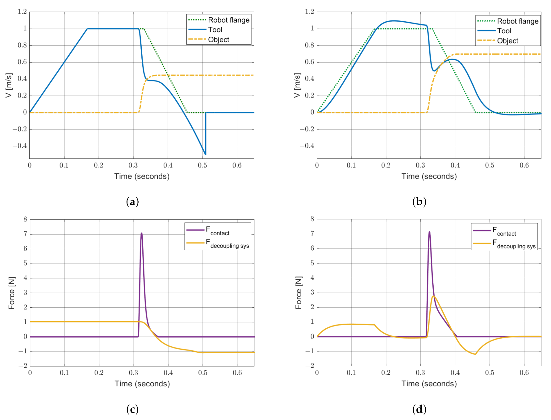
Figure 23a shows the effect of the bi-stable mechanism on the velocities of the tool and of the object, and this is compared with the end-effector comprising a linear spring–damper system (Figure 23b). Figure 23c,d shows the contact force and the total force generated on the tool by the end-effector. The parameters of the simulation were as follows: e = 0.1 , k c = 10 3 N m 1.5 , L 0 = 0.07 m, k = 50 N m , k t = 50 N m , ζ = 1 , m t = 0.125 kg and m p = 0.25 kg.
Figure 23a shows that the tool follows the movement of the robot during the acceleration phase, without oscillating, owing to the positive elastic force applied by the spring on the tool (see Figure 23c). The tool is subjected to a hard deceleration during the collision, since its velocity changes nearly instantaneously from 1.0 m/s to 0.4 m/s. When the tool reaches 0.4 m/s, the effect of the collision is complete, but, when the velocity seems to stabilize, the tool crosses the vertical alignment position of the spring and is pulled back towards the robot flange. The velocity of the tool is subjected to a second rapid change. Then, the tool velocity suddenly adapts to the robot velocity when the tool hits the robot flange. Figure 23c shows that the force applied on the tool by the bi-stable mechanism is lower than the total force generated by the the spring and the damper in the end-effector with the linear behavior (Figure 23d): the force generated in the bi-stable mechanism decreases when the end-effector is compressed. Moreover, the tool is separated from the object after the collision, and this feature leads to the interruption of the momentum transfer. The comparison between the impulses generated by the bi-stable mechanism and by the linear spring–damper system is represented in Figure 24, which clearly shows that the bi-stable mechanism leads to a reduction in the impulse transmitted to the object.
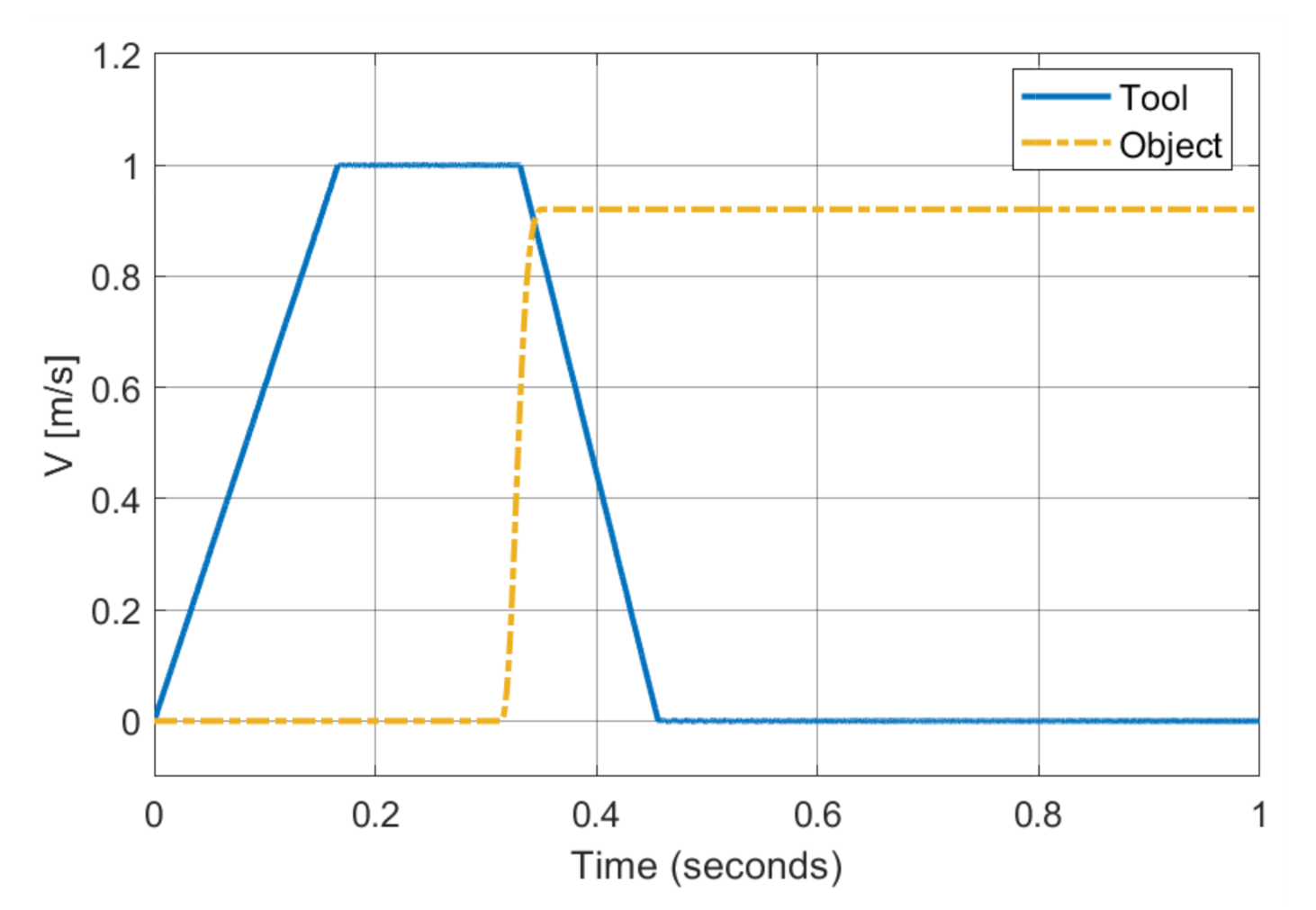
In order to show the effect of the bi-stable mechanism on the velocities of the tool and of the object, Figure 23a is compared with the case in which the tool is rigidly connected to the rigid robot, which is depicted in Figure 25. This comparison shows that the bi-stable mechanism leads to a 51% reduction in the final velocity of the object.

6. Conclusions

The basic analysis carried out with the classical impact theory highlights that reductions in the mass of the tool and in the restitution coefficient result in large decreases in the final velocity of the object. A more detailed model of contact mechanics, taking into account contact stiffness and damping, confirms the previous results. Moreover, the model highlights that a decrease in contact stiffness leads to an increase in contact duration, which can be exploited by the robot control system, which can start braking during the contact with a reduction in the momentum transferred to the object. Reductions in the restitution coefficient and in contact stiffness can be achieved by means of the proper selection of the material of the surface of the tool that impacts the object.
The reduction in the mass of the tool is a more complex problem. In fact, numerical simulations have shown that a relevant share of the mass of the robot moves together with the tool in the approach direction and that the intrinsic compliance of robot joints has a small effect on impact dynamics. Therefore, a proper elastic system that is able to decouple the tool from the robot is needed to minimize the impacting mass. The stiffness of the elastic system has to be sufficient to keep the tool in the desired position when the robot accelerates towards the object. Rebounds of the tool, which give back energy to the object and cause multiple collisions, have to be avoided. These requirements are met by the proposed bi-stable mechanism, that guarantees a reduction in the final velocity of the object of about 50% with respect to the case of a rigid connection between the robot and the tool. The calculated results refer to a tool moving at a velocity of 1 m/s and impacting a stationary object. The extension of the results to different velocities is difficult due to the non-linearities of the system. Some simulations showed that a decrease in the impact velocity may prevent the bi-stable mechanism from reaching the second stable configuration. Conversely, a small increase in the impact velocity does not greatly change the behavior of the system. In fact, the bi-stable mechanism has to be tuned to the impact velocity.
The results obtained in the framework of this research are the starting points for the design of a prototype of an end-effector with a bi-stable mechanism. This prototype is now under construction, and the experimental tests are planned for the spring following the publication of this work.

Author Contributions

Conceptualization, G.C., A.D., G.R., D.T.; methodology G.C., A.D., G.R., D.T.; software, D.T.; validation, G.C.; formal analysis, A.D., G.R.; investigation, G.C., A.D., G.R., D.T.; writing—original draft preparation, D.T.; writing—review and editing, G.C.; supervision, A.D., G.R. All authors have read and agreed to the published version of the manuscript.

Funding

This research was funded by University of Padua—Program BIRD 2018—Project no. BIRD187930.

Conflicts of Interest

The authors declare no conflict of interest.

References

  1. Hokayem, P.F.; Spong, M.W. Bilateral teleoperation: An historical survey. Automatica 2006, 42, 2035–2057. [Google Scholar] [CrossRef]
  2. Hashtrudi-Zaad, K.; Salcudean, S.E. Analysis of control architectures for teleoperation systems with impedance/admittance master and slave manipulators. Int. J. Robot. Res. 2001, 20, 419–445. [Google Scholar] [CrossRef]
  3. Sun, D.; Naghdy, F.; Du, H. Application of wave-variable control to bilateral teleoperation systems: A survey. Annu. Rev. Control 2014, 38, 12–31. [Google Scholar] [CrossRef]
  4. Chan, L.; Naghdy, F.; Stirling, D. Application of adaptive controllers in teleoperation systems: A survey. IEEE Trans. Hum. Mach. Syst. 2014, 44, 337–352. [Google Scholar]
  5. Uddin, R.; Ryu, J. Predictive control approaches for bilateral teleoperation. Annu. Rev. Control 2016, 42, 82–99. [Google Scholar] [CrossRef]
  6. Tai, K.; El-Sayed, A.R.; Shahriari, M.; Biglarbegian, M.; Mahmud, S. State of the art robotic grippers and applications. Robotics 2016, 5, 11. [Google Scholar] [CrossRef] [Green Version]
  7. Rosati, G.; Minto, S.; Oscari, F. Design and construction of a variable-aperture gripper for flexible automated assembly. Robot. Comput. Integr. Manuf. 2017, 48, 157–166. [Google Scholar] [CrossRef]
  8. Brown, M.K. A controlled impedance robot gripper. AT T Tech. J. 1985, 64, 937–969. [Google Scholar] [CrossRef]
  9. Sprovieri, J. Watch your fingers! Assembly 2004, 47, 1–10. [Google Scholar]
  10. Brach, R.M. Mechanical Impact Dynamics: Rigid Body Collisions; John Wiley & Sons: Hoboken, NJ, USA, 2007. [Google Scholar]
  11. Skrinjar, L.; Slavič, J.; Boltežar, M. A review of continuous contact-force models in multibody dynamics. Int. J. Mech. Sci. 2018, 145, 171–187. [Google Scholar] [CrossRef]
  12. Hunt, K.H.; Crossley, F.R.E. Coefficient of restitution interpreted as damping in vibroimpact. J. Appl. Mech. 1975, 42, 440–445. [Google Scholar] [CrossRef]
  13. Marhefka, D.W.; Orin, D.E. Simulation of contact using a nonlinear damping model. In Proceedings of the IEEE International Conference on Robotics and Automation, Minneapolis, MN, USA, 22–28 April 1996; Volume 2, pp. 1662–1668. [Google Scholar]
  14. Schwab, A.; Meijaard, J.; Meijers, P. A comparison of revolute joint clearance models in the dynamic analysis of rigid and elastic mechanical systems. Mech. Mach. Theory 2002, 37, 895–913. [Google Scholar] [CrossRef]
  15. Hu, S.; Guo, X. A dissipative contact force model for impact analysis in multibody dynamics. Multibody Syst. Dyn. 2015, 35, 131–151. [Google Scholar] [CrossRef]
  16. Zhang, H.; Wang, J.; Zhang, G.; Gan, Z.; Pan, Z.; Cui, H.; Zhu, Z. Machining with flexible manipulator: Toward improving robotic machining performance. In Proceedings of the 2005 IEEE/ASME International Conference on Advanced Intelligent Mechatronics, Monterey, CA, USA, 24–28 July 2005; IEEE: Piscataway, NJ, USA, 2005; pp. 1127–1132. [Google Scholar]
  17. Bottin, M.; Cocuzza, S.; Comand, N.; Doria, A. Modeling and Identification of an Industrial Robot with a Selective Modal Approach. Appl. Sci. 2020, 10, 4619. [Google Scholar] [CrossRef]
  18. Doria, A.; Cocuzza, S.; Comand, N.; Bottin, M.; Rossi, A. Analysis of the Compliance Properties of an Industrial Robot with the Mozzi Axis Approach. Robotics 2019, 8, 80. [Google Scholar] [CrossRef] [Green Version]
  19. Siciliano, B.; Sciavicco, L.; Villani, L.; Oriolo, G. Robotics: Modelling, Planning and Control; Springer Science & Business Media: Berlin/Heidelberg, Germany, 2010. [Google Scholar]
  20. OMRON. Omron Adept Viper s650/s850 Robot with MB-60R/eMB-60R User’s Guide; OMRON: Osaka City, Japan, 2016. [Google Scholar]
  21. Bottega, W.J. Engineering Vibrations; CRC Press: Boca Raton, FL, USA, 2014. [Google Scholar]
  22. Borboni, A.; Faglia, R. Parasitic Phenomena in the Dynamics Of Industrial Devices; CRC Press: Boca Raton, FL, USA, 2017. [Google Scholar]
  23. Borboni, A.; Lancini, M.; Faglia, R. Residual Vibration Reduction With Commanded Motion Optimization. Volume 2: Dynamics, Vibration and Control; Energy; Fluids Engineering; Micro and Nano Manufacturing. In Engineering Systems Design and Analysis; ASME: New York, NY, USA, 2014. [Google Scholar]
Figure 1. Instantaneous impacts. (a) A tool rigidly fixed to the robot; (b) a tool decoupled from the robot.
Applsci 10 09077 g001
Figure 2. Influence of e on the end velocities of the tool and of the object.
Applsci 10 09077 g002
Figure 3. Influence of moving mass on end velocities.
Applsci 10 09077 g003
Figure 4. Non-instantaneous impacts. (a) A tool rigidly fixed to the robot; (b) a tool decoupled from the robot.
Applsci 10 09077 g004
Figure 5. Temporal evolution of contact force for the non-linear model. (a) Limit case of Figure 4a; (b) limit case of Figure 4b.
Applsci 10 09077 g005
Figure 6. Influence of kc and e on contact force. (a) Limit case of Figure 4a; (b) limit case of Figure 4b.
Applsci 10 09077 g006
Figure 7. Influence of kc and e on contact duration. (a) Limit case of Figure 4a; (b) limit case of Figure 4b.
Applsci 10 09077 g007
Figure 8. Scheme of the impact between the compliant robot and an object.
Applsci 10 09077 g008
Figure 9. Robot: Adept Viper s650.
Applsci 10 09077 g009
Figure 10. Flow chart of the steps taken to evaluate the terms M X , 11 , D X , 11 and K X , 11 along the trajectory of the tool. DOF: degree of freedom.
Applsci 10 09077 g010
Figure 11. Position and velocity profiles imposed on the tool by the robot control system. The circular dot indicates the impact time.
Applsci 10 09077 g011
Figure 12. Lumped components m r , c r and k r as a function of the imposed position x r . The circular dot indicates the impact time.
Applsci 10 09077 g012
Figure 13. Time history of tool and object velocity. (a) Robot with rigid joints; (b) robot with compliant joints.
Applsci 10 09077 g013
Figure 14. Time history of tool and object velocity. (a) k c = 10 5 N m 1.5 ; (b) k c = 10 6 N m 1.5 .
Applsci 10 09077 g014
Figure 15. Model of the collision between a tool with decoupling elements and an object.
Applsci 10 09077 g015
Figure 16. Effects of the stiffness and of the damping of the decoupling system on the final velocity of the object with e = 1 .
Applsci 10 09077 g016
Figure 17. Velocity comparison: (a) k c = 10 5 N m 1.5 ; (b) k c = 10 4 N m 1.5 . The contact force and total force generated by the decoupling elements are as follows: (c) k c = 10 5 N m 1.5 ; (d) k c = 10 4 N m 1.5 . e = 1 .
Applsci 10 09077 g017
Figure 18. Effects of the impulses of the damping and elastic forces on the final velocity of the object with e = 0.1 .
Applsci 10 09077 g018
Figure 19. Velocity comparison: (a) k c = 10 5 N m 1.5 ; (b) k c = 10 3 N m 1.5 . Contact force and total force generated by the decoupling elements: (c) k c = 10 5 N m 1.5 ; (d) k c = 10 3 N m 1.5 . e = 0.1 .
Applsci 10 09077 g019
Figure 20. Impulse generated by the decoupling system.
Applsci 10 09077 g020
Figure 21. Schematic representation of a bi-stable mechanism with a single spring.
Applsci 10 09077 g021
Figure 22. (a) Tangential force profiles for different values of the parameter H; (b) physical representation of mechanical constraints.
Applsci 10 09077 g022
Figure 23. Velocity comparison: (a) end-effector with bi-stable mechanism; (b) end-effector with a linear spring–damper system. Contact force and total force generated by the end-effector: (c) bi-stable mechanism; (d) linear spring–damper. ( e = 0.1 ).
Applsci 10 09077 g023
Figure 24. Impulse generated by the decoupling system.
Applsci 10 09077 g024
Figure 25. Tool rigidly connected to the rigid robot with e = 0.1 , k c = 10 3 N m 1.5 , m t = 0.125 kg and m p = 0.25 kg.
Applsci 10 09077 g025
Publisher’s Note: MDPI stays neutral with regard to jurisdictional claims in published maps and institutional affiliations.