Article

Polarization-Discriminated RSOA–EAM for Colorless Transmitter in WDM–PON

1
Wuhan National Laboratory for Optoelectronics, Huazhong University of Science and Technology, Wuhan 430074, China
2
Department of Electrical and Computer Engineering, McMaster University, Hamilton, ON L8S 4K2, Canada
*
Author to whom correspondence should be addressed.
Appl. Sci. 2020, 10(24), 9049; https://doi.org/10.3390/app10249049
Submission received: 31 October 2020 / Revised: 16 December 2020 / Accepted: 16 December 2020 / Published: 18 December 2020
(This article belongs to the Special Issue Fiber Optic Communication)

Abstract

:
The integrated reflective semiconductor optical amplifier (RSOA) and electro-absorption modulator (EAM) is viewed as an appealing solution to the colorless transmitter on the optical network unit (ONU) side of wavelength-division multiplexed (WDM) passive optical networks (PONs), for its broad modulation bandwidth and high optical gain. However, the conventional RSOA–EAM usually exhibits a poor upstream signal eye-diagram because it can hardly simultaneously saturate the downstream signal and boost the upstream signal as required. By exploiting the polarization-depended RSOA gain, we propose a polarization-discriminated RSOA–EAM to improve the quality of the upstream signal eye-diagram. In this device, the transverse electric polarized downstream signal is saturated by the high gain in the RSOA active region made of compressively strained multiple quantum wells, whereas the upstream signal is linearly amplified after polarization rotation. We find that, as the quality of the upstream signal eye-diagram improves with an increased polarization rotation angle, its power drops, which indicates that there exists an optimized rotation angle to reach a compromise between the upstream signal integrity and power. Simulation results show that the dynamic extinction ratio and output power of the upstream signal can reach 8.3 dB and 11 dBm, respectively, through the proposed device with its rotation angle set at an optimum value (80°), which exceeds the specification (6 dB and 4 dBm) of the upstream transmitter as required by the next-generation PON stage two. The quality of the upstream signal eye-diagram measured in Q-factor is improved by 10 dB compared to the conventional RSOA–EAM design without polarization rotation introduced.

1. Introduction

With the increasing demand for bandwidth from the subscriber end, it is unlikely that a traditional time-division multiplexed passive optical network (TDM–PON) will satisfy the market’s future requirements [1,2]. As an alternative technology, the wavelength-division multiplexed passive optical network (WDM–PON), which supports a higher bandwidth, better security, and easier upgradability, is promising for future broadband access networks [2,3,4]. However, large-scale deployment of the WDM–PON is rare due to the drastically increased cost on specific wavelength source in optical network units (ONUs) [3,4]. Therefore, the key to reducing the cost of the WDM–PON is to make the ONU colorless, i.e., all ONUs are made identical and interchangeable [5,6]. To this end, many colorless transmitter solutions have been proposed based on the reflective semiconductor optical amplifier (RSOA) or RSOA integrated with an electro-absorption modulator (RSOA–EAM), such as the spectrum-sliced RSOA [7], the RSOA fiber-cavity laser (FCL) [8,9,10,11], the externally seeded RSOA [12,13,14,15], and the wavelength-reuse RSOA [16,17,18,19]. The RSOA–FCL balances the cost and performance among the first three schemes and is thus viable for short-reach applications up to 10 Gb/s [20], but dispersion-shifted fiber (DSF) is required for long reach in preventing multimode dispersion [21]. The wavelength-reuse scheme is free of this requirement, but its upstream performance is subject to the unsuppressed downstream components [17]. Therefore, in the wavelength-reuse configuration, the requirements imposed on such RSOAs/RSOA–EAMs in their simultaneous dealing with the down- and upstream signals are contradictory: The downstream signal needs to be erased by saturated amplification, which requires the SOA to operate in its nonlinear saturated mode, whereas the upstream signal needs to be boosted without distortion, which requires the SOA to operate at its linear amplification state [22]. Obviously, the conventional RSOA/RSOA–EAM design cannot satisfy this contradictory requirement. The quality of its upstream signal eye-diagrams is therefore largely restricted by the extinction ratio (ER) of the downstream signal [16,17,18]. To effectively remove the downstream signal by maximizing the saturation, various structures have been explored, such as the ultralong SOA (UL–SOA) [23], the cascade SOAs/RSOAs [24,25,26], and the self-feedback SOA [27]. These schemes, however, need an extra SOA/RSOA to boost the downstream signal power and a circulator to separate the down- and upstream channels, which increases both device complexity and cost, especially when the circulator cannot be monolithically integrated with the SOA/RSOA with the current technology.
Noticing the difference in the propagation direction between the down- and upstream signals, we recently reported a horn-waveguide RSOA–EAM that simultaneously saturates the downstream signal and linearly amplifies the upstream signal by linearly narrowing the ridge width of the SOA section [22]. Although the asymmetric structure has some advantages over conventional ones, the cross-gain saturation (XGS) may jeopardize the device performance since the down- and upstream signals still share the same material gain [22]. In this work, we propose a polarization-discriminated (PD) RSOA–EAM to deal with the down- and upstream signals in different polarization states. Different from the horn-waveguide RSOA–EAM, the PD RSOA–EAM has a uniform ridge width, but it incorporates a Faraday rotator (FR) at the back end of the RSOA–EAM where the SOA active region is made of compressively strained multiple-quantum-well (CS–MQW). As such, the transverse electric (TE) polarized downstream signal is saturated by the substantial TE gain provided by the CS–MQW active region of the SOA, hence is turned into a DC carrier. Upon the reflection with its polarization state rotated, the DC carrier becomes the upstream signal after its remodulation by the EAM. The upstream signal will be linearly amplified on its returning path in the same SOA, but with its gain greatly suppressed due to the polarization mismatch.
This paper is organized as follows: In the next section, we present the proposed structure and explain its working principle. The influence of the polarization state is shown and the approach to obtain the optimum rotation angle is given in Section 3. We summarize this work in Section 4.

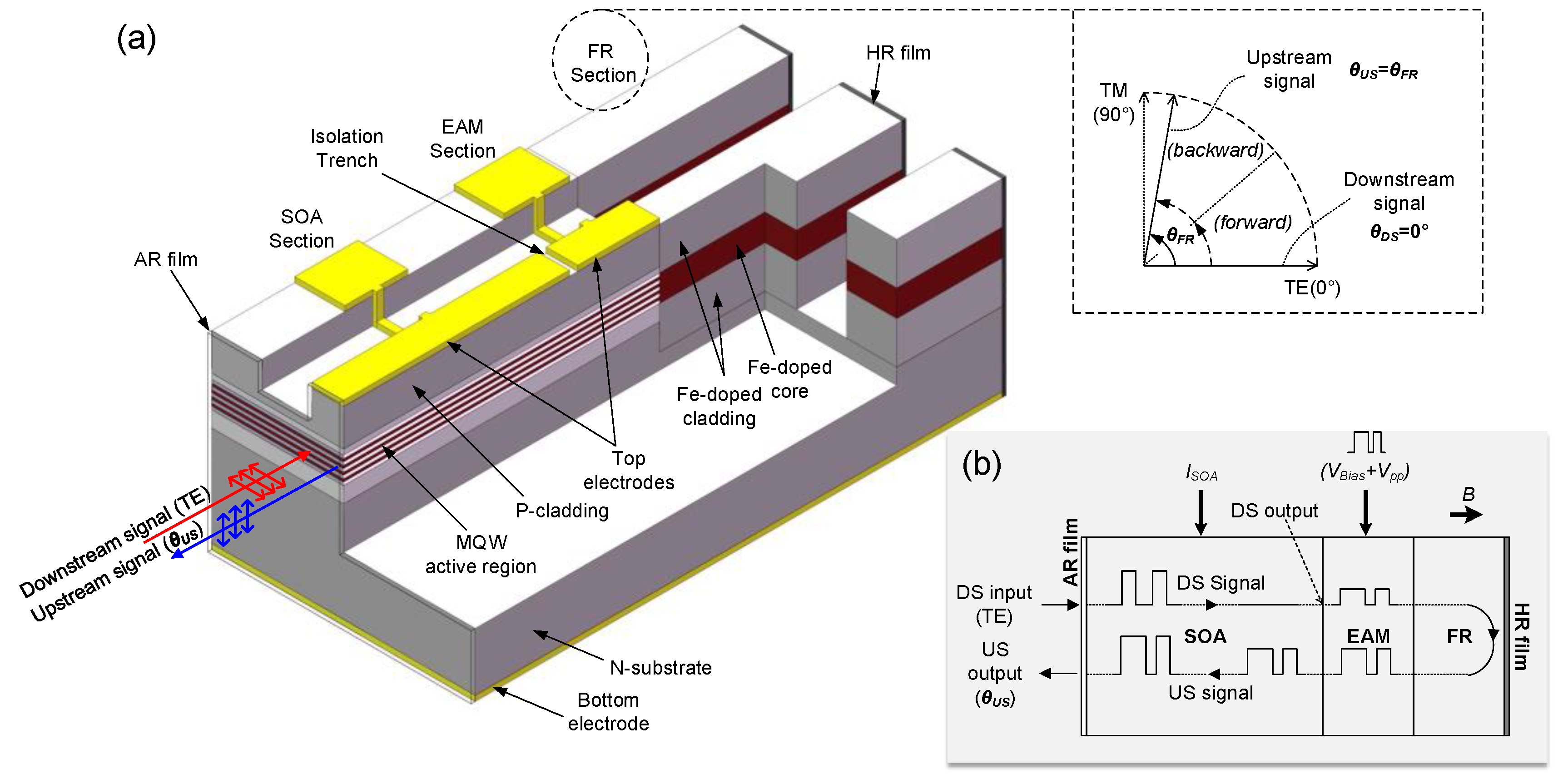
2. Device Structure and Working Principle

The proposed device structure is schematically shown in Figure 1a. It is functionally composed of three sections: the SOA, the EAM, and the FR [28,29], all on III-V compound semiconductors with InP as the common substrate. The active region of the SOA and the EAM both contain MQW structure made by the AlGaInAs materials. The SOA quantum wells are compressively strained to offer a pure TE mode gain, whereas the EAM quantum wells are slightly tensile, strained for polarization independent absorption [30]. Both the SOA and EAM are made of ridge waveguide with a length of 1200 μm and 100 μm, respectively. Their electrodes are separated by an isolation trench typically in 10 μm. The FR is made by Fe-doped InGaAsP/InP material with a bulk core region [29]. The reported Verdet coefficient is up to 33°/mm/T in the FR structure [28]. g the Verdet coefficient [29]) will be able to offer a 90° round-trip Faraday rotation. Hence, a section length of 1 mm under an external magnetic field of 1.37 T [31,32] or less (by increasinIt is worth mentioning that the proposed device shown in Figure 1a needs to be fabricated by the butt-joint regrowth technique due to the inhomogeneity of the material system as well as the layer stack structure in each section. To fabricate the ridge waveguide structure for light guiding and confinement, one may need to exploit different etching depth and/or define different ridge width, in order to achieve a smooth coupling from section to section with negligible reflection and to obtain a strong light confinement, particularly in the FR section for efficiently utilizing the Faraday effect [29].
In this device, the polarization state of the downstream signal ( θ D S ) is chosen as TE, which can be converted from the random polarized light through the polarization diversified circuits [33,34,35]. After the downstream signal has its bit stream pattern erased by the saturation amplification in the SOA, it is uploaded with the upstream signal in the EAM. Upon the reflection of the light, the FR rotates its polarization state by an angle (i.e., θ F R in the inlet of Figure 1a, defined in a round-trip). In the light’s returning path, the upstream signal in a differently polarized state ( θ U S ) will experience a different gain from the downstream signal in the SOA. By exploiting such a polarization-dependent gain discrimination, we can simultaneously saturate the downstream signal and linearly amplify the upstream signal. Apparently, a small (close to 0°) Faraday rotation angle brings in no significant gain discrimination. We will face the contradictory requirement in dealing with the down- and upstream signals in the same SOA, i.e., we can hardly obtain a satisfactory result in erasing the downstream signal (where the SOA needs to be set in its saturation state) and in amplifying the upstream signal (where the SOA needs to be set in its linear amplification region) simultaneously. On the contrary, a large (close to 90°) Faraday rotation angle is in favor of the downstream signal erasing but offers almost no amplification to the upstream signal, as the SOA provides zero gain to the transverse magnetic (TM) mode. An optimum rotation angle, therefore, must exist in balancing the integrity and power of the upstream signal, as the former depends on the erasing of the downstream signal, whereas the later relies on the linear amplification of the upstream signal. A main task of our followed work is to find this optimum rotation angle with different requirements on the upstream signal.

3. Simulation Results and Discussion

The proposed device is simulated with a well-established traveling wave model [36,37], which has incorporated the propagation of both the signal and the broadband noise, the propagation of the TE and TM modes, and the evolution of the carrier and photon density along the cavity. For more details of the model and its numerical implementation, please see the Supplementary Material. With the material and structural parameters listed in Table 1, the separated SOA and EAM sections are first characterized by the simulation model, respectively. The gain and the saturation input power [38] of the separated SOA section at different polarizations are plotted in Supplementary Figure S2a, and the EAM single-pass transmission curve is plotted in Supplementary Figure S2b. As shown in Supplementary Figure S2a, the gain discrimination between the TE and TM modes is around 40 dB for a bias current of 100 mA, and is enhanced with an increased SOA bias. The saturation input power of the SOA is raised with an increased polarization angle from 0° to 90°. Since the linear and nonlinear response regimes depend on the saturation input power [38], and considering a nonlinear response is required to erase the downstream signal while a linear response is required by the upstream signal, the down- and upstream polarizations should therefore be aligned at 0° (maximize the nonlinear regime) and close to 90° (maximize the linear regime), respectively. The single-pass insertion loss in the EAM section is about 1.5 dB and doubles for a round-trip. The static single/double-pass extinction ratio is around 10/20 dB with an EAM bias voltage of −1 V plus a peak-peak voltage (Vpp) of 2 V (see Supplementary Figure S2b).

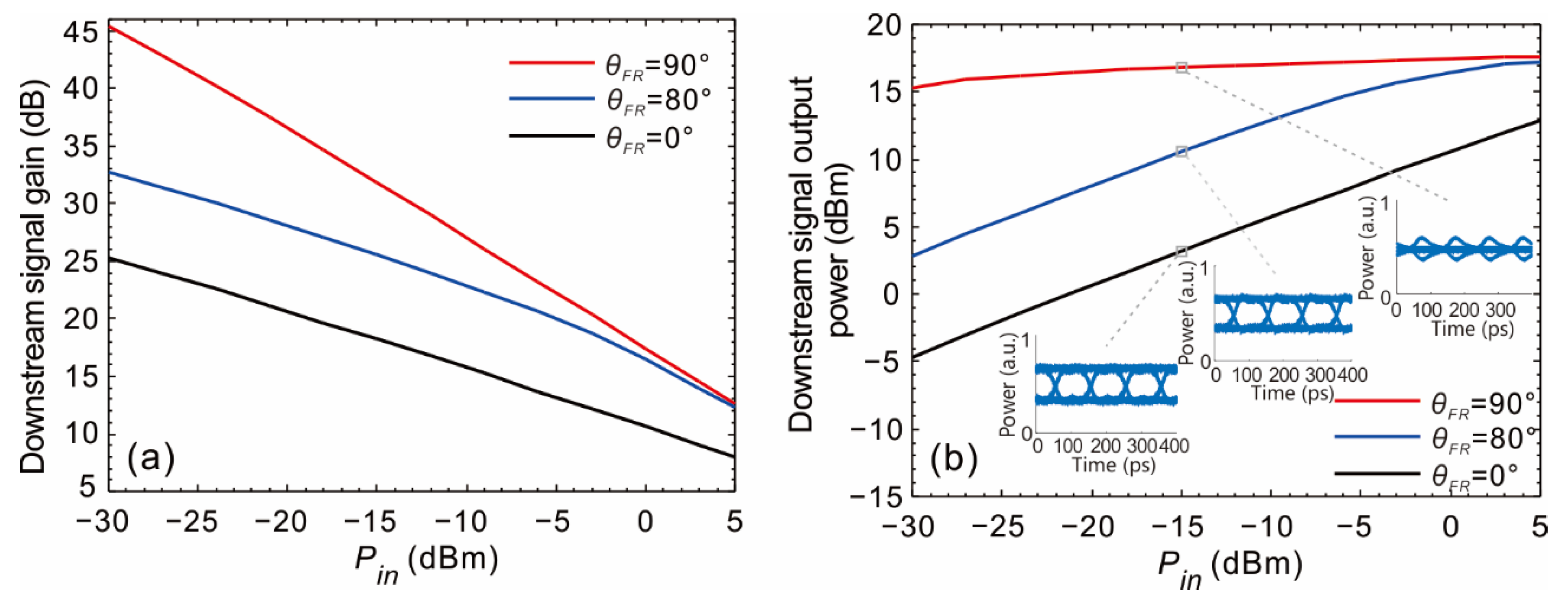
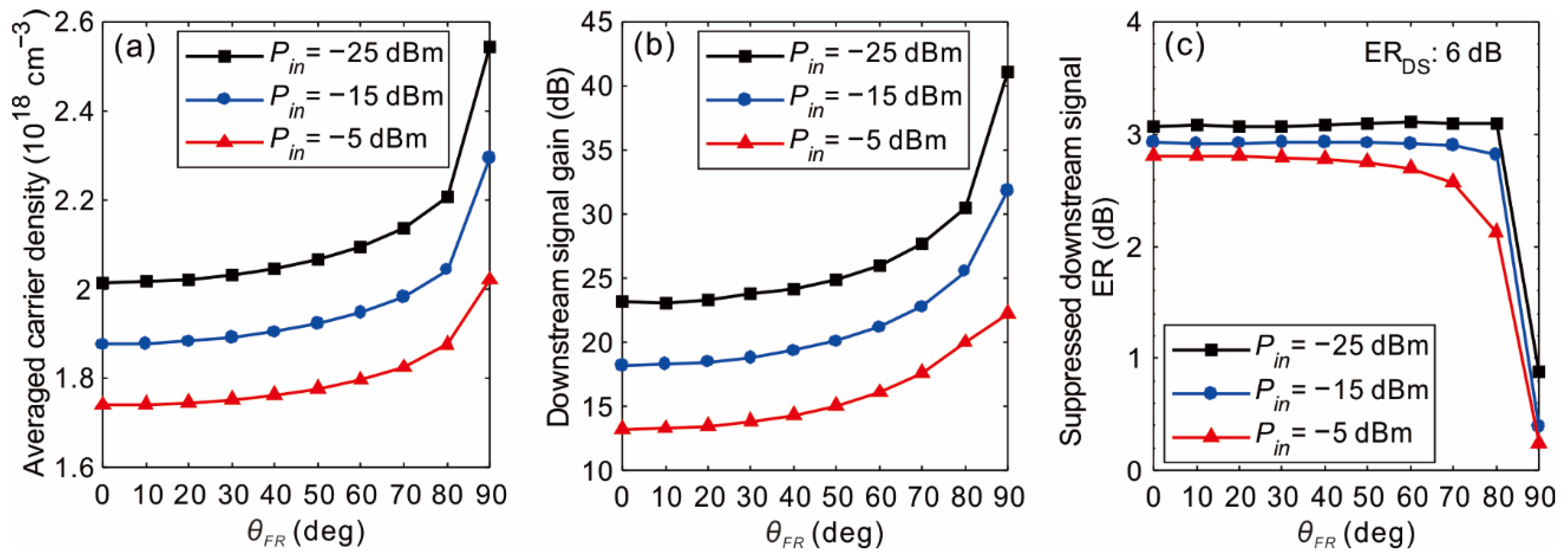
3.1. Downstream Signal Suppression

Figure 1b depicts the schematic operation diagram of the proposed device. In this subsection, the downstream signal suppression is studied during its first pass in the SOA, taking into account the gain affected by the contribution of the reflected light. The EAM section is biased at 0 V without modulation (i.e., Vpp = 0), and the suppressed downstream signal is extracted before entering the EAM. The SOA section is biased at a constant current of 150 mA.
Figure 2a plots the static gain saturation curves of the 1550 nm downstream signal when θ F R varies from 0° to 90° (with θ D S fixed at 0°). The corresponding relationships between the downstream signal output and input powers are shown in Figure 2b, where the erased 10 Gbps eye- diagrams at a downstream signal input power ( P i n ) of −15 dBm are inserted to show the erasing effects. It is apparent that, as the Faraday rotation angle increases from 0° to 90°, the downstream signal saturation is more pronounced as evidenced by the deeper slope of the gain saturation curve. Consequently, a cleaner seed DC light is obtainable, as shown by the drastically reduced ER in the eye-diagram at θ F R = 90° as compared to θ F R = 0° (see Figure 2b). These results indicate that a large (close to 90°) Faraday rotation angle is in favor of the downstream signal erasing.
To understand the results in Figure 2, one should keep in mind that a higher SOA gain leads to more severe SOA saturation [40], hence one should keep the gain as high as possible during the first pass to suppress the downstream signal. Since the material gain is related to the carrier density (N) by g 0 ln ( N / N t r ) [37,41] (with g 0 and N t r indicating the gain coefficient and transparent carrier density, respectively), we should preserve more carriers for the downstream signal. As indicated in Figure 3a, the averaged carrier density inside the active region of the SOA increases with an increased Faraday rotation angle (this is attributed to the decreased carrier consumption of the upstream light, since the upstream light TE mode power decreases with the Faraday rotation angle following Equation (S9a) in Supplementary Material, whereas the upstream light TM mode does not consume carriers at all [37,42]). Therefore, the increased carrier density in turn provides increased gain to the downstream signal, as shown in Figure 3b, through which the saturation is enhanced, hence the cleaner erasing of the downstream signal is obtained.
The ER of the suppressed downstream signal is plotted in Figure 3c as a function of the Faraday rotation angle. Compared to the situation without any rotation (0°), the suppression of the downstream signal is further improved by more than 2 dB in addition to the normal 3 dB suppression, when the Faraday rotation angle is 90°.
The device’s colorless working ability is also characterized and shown in Figure S3 in the Supplementary Material. The ER of the incident downstream signal is 6 dB and the rotation angle is 90°. It is seen that the colorless working range is significantly broadened as the downstream signal input power increases from −25 dBm to −5 dBm. Nonetheless, the suppressed downstream signal ER can be kept below 2 dB for a broad wavelength span from 1505 nm to around 1560 nm, when the input power is not less than −25 dBm.

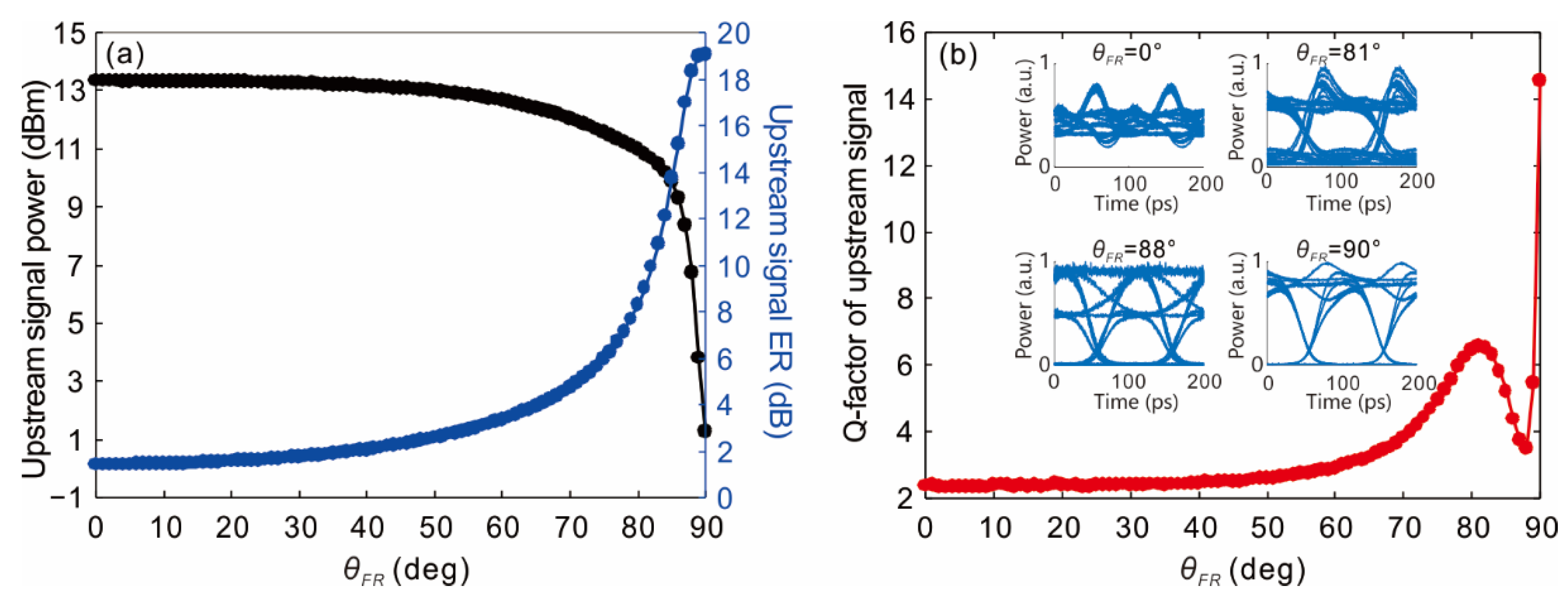
3.2. Upstream Signal Integrity and Power

In addition to erasing the downstream signal, the device also needs to linearly amplify the upstream signal in its returning path to provide sufficient upstream launch power. Apparently a 90° Faraday rotation angle will fail to achieve any signal amplification as the SOA provides zero gain to the TM mode (see Supplementary Figure S2a). We therefore need to reduce the Faraday rotation angle from 90° on the premise of maintaining the upstream signal integrity.
In this subsection, the EAM is biased at −1 V and driven by an upstream signal bit stream (10 Gbps NRZ-OOK) with a peak-peak voltage of 2 V. The upstream output signal is extracted at the “upstream output” point in Figure 1b. The SOA is biased at a constant current of 150 mA. The input power and ER of the downstream signal are −10 dBm and 6 dB, respectively. Figure 4 presents the simulated Faraday rotation angle dependence of the output power ( P u s ) (Figure 4a), dynamic ER (Figure 4a), and Q-factor (Figure 4b) of the upstream signal, where the Q-factor is a measure of the eye-diagram quality [43]. The inlets in Figure 4b are the 10 Gbps upstream signal eye-diagrams at different Faraday rotation angles. As can be seen in Figure 4a, the upstream signal dynamic ER increases, but its output power drops monotonically with an increased Faraday rotation angle. The Q-factor, however, has a maximum and a minimum in the close neighborhood of the 90° Faraday rotation angle. The reduced output power and increased dynamic ER of the upstream signal are caused by the reduced upstream signal gain and decreased gain saturation, respectively, with an increase of the Faraday rotation angle. Following the specification of the next-generation PON stage two (NG–PON2) on the upstream signal launch power (>4 dBm) and dynamic ER (>6 dB) [44], the Faraday rotation angle should be set in the range of 0–88° and 75–90°, respectively. Therefore, a Faraday rotation angle within 75° and 88° will simultaneously satisfy the upstream signal power and the dynamic ER as required by NG–PON2.
Attention should be paid that a high dynamic ER does not necessarily mean a high quality of the eye-diagram, as the Q-factor also reflects the level of crosstalk, whereas the ER does not. As shown in Figure 4b, if the Faraday rotation angle falls between 81° and 88°, the Q-factor drops significantly. As such, the eye-diagram at a Faraday rotation angle of 88° is worse than that at 81°, as shown in the inlets of Figure 4b, although the dynamic ER in the former case with a higher rotation angle is almost 9 dB higher. The Q-factor valley in the vicinity of 88° is caused by the pronounced crosstalk due to the XGS between the down- and upstream signals (see the stratified “1” level in the eye-diagram at 88° in Figure 4b). At a Faraday rotation angle close to but not exactly at 90°, the upstream signal has a none-zero TE component according to Equation (S9a). Since the SOA is in deep saturation, the XGS effect transfers the downstream signal pattern onto the upstream signal, as the latter’s nonvanishing TE mode power fluctuates anticorrelatedly with the former’s (TE mode) power.
To be able to find an optimum rotation angle that makes a compromise between the upstream signal integrity and power, we introduce the following dimensionless figure of merit (FOM):
F O M = Q 2 × P u s ( mW ) P i n ( mW ) ,
The dependence of the total gain ( P u s / P i n ) and Q 2 are plotted in Figure 5a, and the FOM is plotted in Figure 5b, respectively, both as a function of the Faraday rotation angle. As a FOM peak appears at 80°, we know that the device will offer an overall best performance at this optimum Faraday rotation angle. At this angle (80°), the output power and dynamic ER of the upstream signal are 11 dBm and 8.3 dB, respectively, exceeding the minimum required value at 4 dBm and 6 dB, respectively, as specified by NG–PON2. To further clarify the effectiveness of the device, in Figure 5c we plot the one-way static gain for signals going downstream (at 0° or TE mode, from left to right) and upstream (at 80°, from right to left), respectively, when only the down- or upstream signal is inside the cavity (i.e., without XGS) and when they both exist inside the cavity (i.e., with XGS). For the case without XGS, we find that the SOA is well-saturated for an input power higher than −30 dBm along the downstream path, whereas the SOA is in its linear amplification region for an input power lower than −20 dBm along the upstream path, which indicates that the proposed PD RSOA–EAM can indeed erase the downstream signal and linearly amplify the upstream signal simultaneously. The device’s fairly wide working range (from −30 dBm to −20 dBm, i.e., where the saturation discrimination can be achieved) facilitates the power management in operation, hence is superior to the conventional design without utilizing the polarization dimension, not only in terms of the gain discrimination scale, but also in terms of the power operation range. When both the down- and upstream signals exist inside the cavity, the XGS will bring in extra saturation compared to that without XGS, as shown by the lower output powers in Figure 5c. By utilization of polarization discrimination, however, even under XGS we still manage to have the downstream signal saturated and the upstream signal linearly amplified. Although the saturation of the downstream signal is not as good and the linear gain of the upstream signal is lower, the gain difference between the down- and upstream signals brought in by the polarization discrimination still exists nonetheless, which is not achievable in a straight SOA design without using the polarization dimension [22].
Figure 6 gives a comparison of the FOM calculated from the proposed device (when the rotation angle is set at 0° and 84°, respectively) and measured with the horn-waveguide RSOA–EAM [22] as referred to in the introduction. The inlets are the corresponding upstream signal eye-diagrams at output. The downstream input signal power is −14 dBm, and the EAM is modulated at 5 Gbps as performed in [22] for a fair comparison. In addition, note that the rotation angle is changed to 84° instead of 80° because the optimum rotation angle varies with the input power, as will be discussed later. The ER of the downstream input signal is increased from 0 dB (i.e., downstream CW) to 5 dB. It is seen from Figure 6 that both the horn structure and the polarization rotation design can improve the FOM, while the polarization rotation design is more advantageous. It is also observed that the two schemes can both improve the quality of the upstream signal eye-diagram. Measured in Q-factor, the improvements are 3.7 dB and 10 dB, respectively, for the horn RSOA–EAM and the PD RSOA–EAM with θ F R set at 84°. Meanwhile, for high ERs (e.g., 5 dB) of the downstream input signal, the PD RSOA–EAM (at 84°) can significantly reduce the XGS effect when compared to the horn-waveguide RSOA–EAM, as evidenced by its much thinner “1” level.
In practical applications, the downstream signal input power may vary among different ONUs at different locations in the WDM–PON. Its impact on the optimum rotation angle therefore needs to be studied. Figure 7a plots the normalized FOM as a function of the rotation angle at different downstream signal input powers. As the downstream signal input power increases from −25 dBm to −5 dBm, the optimum rotation angle decreases from 88° to 73° correspondingly, which is further plotted in Figure 7b. This effect indicates that for an ONU placed closer to the remote node (RN), the rotation angle of the proposed device should be set at a smaller value for achieving its best performance (we define it as “adaptive θ F R ”). Figure 7a also indicates that the full width at half- maximum (FWHM) of the FOM can be broadened with an increased input power, which means that higher input powers are beneficial to relax the fabrication requirements as the optimum rotation angle is easier to hit.
To show the device performance differences with an adaptive θ F R and a constant θ F R (i.e., θ F R irrespective to the downstream signal input power), their Q-factors are plotted as a function of the downstream signal input power in Figure 7c. It is found that the adaptive θ F R in general gives the highest Q-factors, the constant θ F R of 87° favors the relatively low input powers (around −20 dBm), and the constant θ F R of 80° favors the relatively high input powers (around −10 dBm). Nonetheless, they all give higher Q-factors than the constant θ F R of 0°, i.e., the design without polarization rotation.
Finally, to verify the colorless operation potential of the proposed device, Figure S4 (see the Supplementary Material) plots the wavelength dependence of the output power and Q-factor of the upstream signal when the downstream signal input power is −15 dBm and the rotation angle is 84°. We can find that the full width half-maximum (FWHM) optical bandwidth of both the integrity (the Q-factor) and the power of the upstream signal are larger than 50 nm, sufficient to cover the 20 nm wideband operation requirement as specified by NG–PON2 [44].

4. Conclusions

In summary, we have proposed a PD RSOA–EAM to discriminately processes the down- and upstream signals at a different polarization state. Influences of the rotation angle on both the down- and upstream signals have been studied. An increased rotation angle enhances the downstream signal erasing, hence improving the dynamic ER of the upstream signal eye-diagram at a cost of the low upstream output signal power. An optimum rotation angle always exists at which the upstream signal output power and integrity are both guaranteed. With the polarization state exploited as an extra dimension, the proposed device can simultaneously saturate the downstream signal and linearly amplify the upstream signal in a fairly wide power operation range. As evidenced by the simulation result, our proposed device can significantly improve the eye-diagram quality and raise the output power of the upstream signal. Hence, the proposed PD RSOA–EAM is promising as a colorless transmitter solution to ONUs in the WDM–PON.

Supplementary Materials

The following are available online at https://www.mdpi.com/2076-3417/10/24/9049/s1, 1. Theoretical Models for the proposed PD RSOA-EAM. 2. Numerical Implementation. 3. Numerical Simulation Results. Figure S1: Schematic diagram of the simulation setup for polarization-discriminated RSOA–EAM. Figure S2a: Static gain of the single SOA section (at an input power of −25 dBm) and the SOA saturation input power as a function of the input polarization angle. Figure S2b: Static single-pass extinction curve of the EAM section with different powers injected into the EAM section. Figure S3: ER of the suppressed downstream signal as functions of the downstream signal wavelength. Figure S4: Output power and Q-factor of the upstream signal as functions of the downstream signal wavelength.

Author Contributions

Supervision, X.L.; Writing—original draft preparation, C.Z.; Writing—review and editing, C.Z. Both authors have read and agreed to the published version of the manuscript.

Funding

This research received no external funding.

Conflicts of Interest

The authors declare no conflict of interest.

References

  1. Banerjee, A.; Park, Y.; Clarke, F.; Song, H.; Yang, S.; Kramer, G.; Kim, K.; Mukherjee, B. Wavelength-division-multiplexed passive optical network (WDM-PON) technologiesfor broadband access: A review. J. Opt. Netw. 2005, 4, 737–758. [Google Scholar] [CrossRef]
  2. An, F.-T.; Kim, K.S.; Gutierrez, D.; Yam, S.; Hu, E.; Shrikhande, K.; Kazovsky, L.G. Success: A next-generation hybrid WDM/TDM optical access network architecture. J. Lightwave Technol. 2004, 22, 2557–2569. [Google Scholar] [CrossRef]
  3. Feldman, R.D.; Harstead, E.; Jiang, S.; Wood, T.H.; Zirngibl, M. An evaluation of architectures incorporating wavelength division multiplexing for broad-band fiber access. J. Lightwave Technol. 1998, 16, 1546. [Google Scholar] [CrossRef]
  4. An, F.-T.; Kim, K.S.; Hsueh, Y.-L.; Rogge, M.; Shaw, W.-T.; Kazovsky, L. Evolution, challenges and enabling technologies for future WDM-based optical access networks. In Proceedings of the 2nd Symposium on Photonics, Networking, and Computing, Cary, NC, USA, 26–30 September 2003; pp. 26–30. [Google Scholar]
  5. Wey, J.S.; Zhang, J. Passive Optical Networks for 5G Transport: Technology and Standards. J. Lightwave Technol. 2019, 37, 2830–2837. [Google Scholar] [CrossRef]
  6. Lu, Y.; Huang, G.; Bi, M.; Hu, M.; Yang, G.; Zhou, X. Flexible migration and colorless ONUs for future PON based on simple line-coding. Opt. Fiber Technol. 2019, 49, 57–63. [Google Scholar] [CrossRef]
  7. Park, S.; Jung, D.K.; Shin, D.J.; Shin, H.S.; Yun, I.K.; Lee, J.S.; Oh, Y.K.; Oh, Y.J. Colorless Operation of WDM-PON Employing Uncooled Spectrum-Sliced Reflective Semiconductor Optical Amplifiers. IEEE Photon. Technol. Lett. 2007, 19, 248–250. [Google Scholar] [CrossRef]
  8. Cikan, N.N.; Aksoy, M. A Review of Self-Seeded RSOA Based on WDM PON. Can. J. Electr. Comput. Eng. 2019, 42, 2–9. [Google Scholar] [CrossRef]
  9. Gebrewold, S.A.; Bonjour, R.; Brenot, R.; Hillerkuss, D.; Leuthold, J. Bit- and Power-Loading—A Comparative Study on Maximizing the Capacity of RSOA Based Colorless DMT Transmitters. Appl. Sci. 2017, 7, 999. [Google Scholar] [CrossRef] [Green Version]
  10. Wong, E.; Lee, K.L.; Anderson, T.B. Directly modulated self-seeding reflective semiconductor optical amplifiers as colorless transmitters in wavelength division multiplexed passive optical networks. J. Lightwave Technol. 2007, 25, 67–74. [Google Scholar] [CrossRef]
  11. Zhan, W.; Zhou, P.; Zeng, Y.; Mukaikubo, M.; Tanemura, T.; Nakano, Y. Optimization of Modulation-Canceling Reflective Semiconductor Optical Amplifier for Colorless WDM Transmitter Applications. J. Lightwave Technol. 2017, 35, 274–279. [Google Scholar] [CrossRef]
  12. Atra, K.; Cerulo, G.; Provost, J.; Jorge, F.; Blache, F.; Mekhazni, K.; Garreau, A.; Pommereau, F.; Gomez, C.; Fortin, C.; et al. O-Band Reflective Electroabsorption Modulator for 50 Gb/s NRZ and PAM-4 Colorless Transmission. In Proceedings of the 2020 Optical Fiber Communications Conference and Exhibition (OFC), San Diego, CA, USA, 8–12 March 2020; pp. 1–3. [Google Scholar]
  13. Kim, H.-S.; Kim, D.C.; Kim, K.-S.; Choi, B.-S.; Kwon, O.K. 10.7 Gb/s reflective electroabsorption modulator monolithically integrated with semiconductor optical amplifier for colorless WDM-PON. Opt. Express 2010, 18, 23324–23330. [Google Scholar] [CrossRef]
  14. Smith, D.; Lealman, I.; Chen, X.; Moodie, D.; Cannard, P.; Dosanjh, J.; Rivers, L.; Ford, C.; Cronin, R.; Kerr, T. Colourless 10 Gb/s reflective SOA-EAM with low polarization sensitivity for long-reach DWDM-PON networks. In Proceedings of the 2009 35th European Conference on Optical Communication (ECOC), Vienna, Austria, 20–24 December 2009. [Google Scholar]
  15. Cho, K.; Choi, B.; Takushima, Y.; Chung, Y. 25.78-Gb/s operation of RSOA for next-generation optical access networks. IEEE Photonics Technol. Lett. 2011, 23, 495–497. [Google Scholar] [CrossRef]
  16. Lee, W.; Park, M.Y.; Cho, S.H.; Lee, J.; Kim, C.; Jeong, G.; Kim, B.W. Bidirectional WDM-PON based on gain-saturated reflective semiconductor optical amplifiers. IEEE Photonics Technol. Lett. 2005, 17, 2460–2462. [Google Scholar]
  17. Papagiannakis, I.; Omella, M.; Klonidis, D.; Lázaro Villa, J.A.; Birbas, A.N.; Kikidis, J.; Tomkos, I.; Prat, J. Design Characteristics for a Full-Duplex IM/IM Bidirectional Transmission at 10 Gb/s Using Low Bandwidth RSOA. J. Lightwave Technol. 2010, 28, 1094–1101. [Google Scholar] [CrossRef]
  18. Schrenk, B.; Bonada, F.; Lazaro, J.A.; Prat, J. Remotely Pumped Long-Reach Hybrid PON With Wavelength Reusein RSOA-Based ONUs. J. Lightwave Technol. 2011, 29, 635–641. [Google Scholar] [CrossRef]
  19. Dúill, S.Ó.; Marazzi, L.; Parolari, P.; Brenot, R.; Koos, C.; Freude, W.; Leuthold, J. Efficient modulation cancellation using reflective SOAs. Opt. Express 2012, 20, B587–B594. [Google Scholar] [CrossRef] [PubMed] [Green Version]
  20. Gebrewold, S.; Bonjour, R.; Barbet, S.; Maho, A.; Brenot, R.; Chanclou, P.; Brunero, M.; Marazzi, L.; Parolari, P.; Totovic, A.; et al. Self-Seeded RSOA-Fiber Cavity Lasers vs. ASE Spectrum-Sliced or Externally Seeded Transmitters—A Comparative Study. Appl. Sci. 2015, 5, 1922. [Google Scholar] [CrossRef] [Green Version]
  21. Gebrewold, S.A.; Marazzi, L.; Parolari, P.; Brenot, R.; Dúill, S.P.Ó.; Bonjour, R.; Hillerkuss, D.; Hafner, C.; Leuthold, J. Reflective-SOA Fiber Cavity Laser as Directly Modulated WDM-PON Colorless Transmitter. IEEE J. Sel. Top. Quantum Electron. 2014, 20, 503–511. [Google Scholar] [CrossRef]
  22. Zuo, C.; Li, X.; Xia, Y.; Dai, X.; Wang, L. Horn-Waveguide RSOA-EAM as a Colorless Emitting Source with Reduced Crosstalk. J. Lightwave Technol. 2018, 36, 5942–5948. [Google Scholar] [CrossRef]
  23. Ribeiro, N.S.; Cavalcante, A.R.; Gallep, C.M.; Conforti, E. Data Rewriting After Carrier Erasing by Ultra-Long SOA. In Proceedings of the Optical Fiber Communication Conference/National Fiber Optic Engineers Conference 2011, Los Angeles, CA, USA, 6 March 2011; p. JWA042. [Google Scholar]
  24. Lee, J.H.; Cho, S.; Jang, Y.S.; Lee, S. Enhancement of power budget in RSOA based loop-back type WDM-PON by using the cascaded RSOAs. In Proceedings of the 2010 12th International Conference on Transparent Optical Networks, Munich, Germany, 27 June–1 July 2010; pp. 1–4. [Google Scholar]
  25. Feng, H.; Ge, J.; Xiao, S.; Fok, M.P. Suppression of Rayleigh backscattering noise using cascaded-SOA and microwave photonic filter for 10 Gb/s loop-back WDM-PON. Opt. Express 2014, 22, 11770–11777. [Google Scholar] [CrossRef]
  26. Celino, D.R.; Duarte, U.R.; Romero, M.A. Improved self-seeding and carrier remodulation performance for WDM-PON by means of double RSOA erasure. Opt. Commun. 2020, 459, 125018. [Google Scholar] [CrossRef]
  27. Chi, Y.; Lin, C.; Lin, S.; Lin, G. The Reuse of Downstream Carrier Data Erased by Self-Feedback SOA for Bidirectional DWDM-PON Transmission. J. Lightwave Technol. 2012, 30, 3096–3102. [Google Scholar] [CrossRef]
  28. Zaman, T.; Guo, X.; Ram, R.J. Waveguide Faraday rotation in Fe: InGaAsP. In Proceedings of the 2006 Conference on Lasers and Electro-Optics and 2006 Quantum Electronics and Laser Science Conference, Long Beach, CA, USA, 21–26 May 2006; pp. 1–2. [Google Scholar]
  29. Zaman, T.R.; Guo, X.; Ram, R.J. Faraday rotation in an InP waveguide. Appl. Phys. Lett. 2007, 90, 023514. [Google Scholar] [CrossRef]
  30. Aizawa, T.; Ravikumar, K.G.; Suzaki, S.; Watanabe, T.; Yamauchi, R. Polarization-independent quantum-confined Stark effect in an InGaAs/InP tensile-strained quantum well. IEEE J. Quantum Electron. 1994, 30, 585–592. [Google Scholar] [CrossRef]
  31. Fischbacher, J.; Kovacs, A.; Gusenbauer, M.; Oezelt, H.; Exl, L.; Bance, S.; Schrefl, T. Micromagnetics of rare-earth efficient permanent magnets. J. Phys. D Appl. Phys. 2018, 51, 193002. [Google Scholar] [CrossRef]
  32. Sagawa, M.; Hirosawa, S.; Tokuhara, K.; Yamamoto, H.; Fujimura, S.; Tsubokawa, Y.; Shimizu, R. Dependence of coercivity on the anisotropy field in the Nd2Fe14B-type sintered magnets. J. Appl. Phys. 1987, 61, 3559–3561. [Google Scholar] [CrossRef]
  33. Dai, D.; Wu, H. Realization of a compact polarization splitter-rotator on silicon. Opt. Lett. 2016, 41, 2346–2349. [Google Scholar] [CrossRef]
  34. Ma, M.; Murray, K.; Ye, M.; Lin, S.; Wang, Y.; Lu, Z.; Yun, H.; Hu, R.; Jaeger, N.A.F.; Chrostowski, L. Silicon Photonic Polarization Receiver with Automated Stabilization for Arbitrary Input Polarizations. In Proceedings of the Conference on Lasers and Electro-Optics, San Jose, CA, USA, 5 June 2016; p. STu4G.8. [Google Scholar]
  35. Fukuda, H.; Yamada, K.; Tsuchizawa, T.; Watanabe, T.; Shinojima, H.; Itabashi, S.-i. Silicon photonic circuit with polarization diversity. Opt. Express 2008, 16, 4872–4880. [Google Scholar] [CrossRef]
  36. Park, J.; Li, X.; Huang, W.-P. Performance simulation and design optimization of gain-clamped semiconductor optical amplifiers based on distributed Bragg reflectors. IEEE J. Quantum Electron. 2003, 39, 1415–1423. [Google Scholar] [CrossRef]
  37. Li, X. Optoelectronic Devices: Design, Modeling, and Simulation; Cambridge University Press: Cambridge, UK, 2009; pp. 1–361. [Google Scholar] [CrossRef]
  38. Bonk, R.; Huber, G.; Vallaitis, T.; Koenig, S.; Schmogrow, R.; Hillerkuss, D.; Brenot, R.; Lelarge, F.; Duan, G.H.; Sygletos, S.; et al. Linear semiconductor optical amplifiers for amplification of advanced modulation formats. Opt. Express 2012, 20, 9657–9672. [Google Scholar] [CrossRef] [Green Version]
  39. Talli, G.; Adams, M.J. Gain dynamics of semiconductor optical amplifiers and three-wavelength devices. IEEE J. Quantum Electron. 2003, 39, 1305–1313. [Google Scholar] [CrossRef]
  40. Takesue, H.; Sugie, T. Wavelength channel data rewrite using saturated SOA modulator for WDM networks with centralized light sources. J. Lightwave Technol. 2003, 21, 2546–2556. [Google Scholar] [CrossRef]
  41. Makino, T. Analytical formulas for the optical gain of quantum wells. IEEE J. Quantum Electron. 1996, 32, 493–501. [Google Scholar] [CrossRef]
  42. Chuang, S.L.; Peyghambarian, N.; Koch, S. Physics of Optoelectronic Devices. Phys. Today 1996, 49, 62. [Google Scholar] [CrossRef] [Green Version]
  43. Bergano, N.S.; Kerfoot, F.W.; Davidsion, C.R. Margin measurements in optical amplifier system. IEEE Photon. Technol. Lett. 1993, 5, 304–306. [Google Scholar] [CrossRef]
  44. ITU-T, G. 989.2 40-Gigabit-Capable Passive Optical Networks 2 (NG-PON2): Physical Media Dependent (PMD) Layer Specification; International Telecommunication Union: Geneve, Switzerland, 2014. [Google Scholar]
Figure 1. (a) Schematic three-dimensional view of the proposed polarization-discriminated (PD) reflective semiconductor optical amplifier electro-absorption modifier (RSOA–EAM), and (b) Schematic diagram for the device operation. ( θ D S : polarization angle of the input downstream signal; θ U S : polarization angle of the input upstream signal; θ F R : the round-trip Faraday rotation angle; HR: high reflective; AR: antireflective; DS: downstream; US: upstream).
Applsci 10 09049 g001
Figure 2. (a) The gain saturation curves of the downstream signal at different Faraday rotation angles. (b) The downstream signal output power versus the input power at different Faraday rotation angles. The inlets show the erased eye-diagrams when the input power is −15 dBm. Note that the output powers and eye-diagrams are extracted from the suppressed downstream signal before entering the EAM.
Applsci 10 09049 g002
Figure 3. (a) Averaged carrier density inside the SOA active region, (b) the downstream signal gain, and (c) extinction ratio (ER) of the suppressed downstream signal as functions of the Faraday rotation angle. (ERDS: ER of the downstream signal at input).
Applsci 10 09049 g003
Figure 4. Faraday rotation angle dependence of the (a) upstream signal power and dynamic ER, and (b) Q-factor. Inlets are the 10 Gbps upstream signal eye-diagrams at different Faraday rotation angles. (downstream signal power at input: −10 dBm, ER: 6 dB, wavelength: 1550 nm; SOA DC bias current: 150 mA; EAM bias voltage: −1 V, EAM peak-peak voltage: 2 V).
Applsci 10 09049 g004
Figure 5. Dependence of (a) total gain P u s / P i n and Q 2 , and (b) figure of merit (FOM) on the rotation angle when the downstream input signal power is −10 dBm. (c) One-way static gain characteristics along the downstream and upstream paths, respectively, with and without considering the XGS effect.
Applsci 10 09049 g005
Figure 6. FOM versus the downstream input signal ER of the horn-waveguide RSOA–EAM [22], and of the proposed PD RSOA–EAM at a rotation angle of 0° and 84°. The inlets are the upstream signal eye-diagrams (data rates of the down- and upstream signals: 10 Gbps and 5 Gbps, respectively).
Applsci 10 09049 g006
Figure 7. (a) Normalized FOM as functions of the rotation angle at different downstream signal input powers. (b) The optimum rotation angle as a function of the downstream signal input power. (c) The Q-factors obtained with an adaptive θ F R , a constant θ F R at 87°, a constant θ F R at 80°, and a constant θ F R at 0°, respectively, as a function of the downstream signal input power. The ER of the downstream input signal is 6 dB.
Applsci 10 09049 g007
Table 1. Parameters of the Proposed PD RSOA–EAM.
SOA ParametersValueEAM/FR ParametersValue
SOA length (μm)1200EAM length (μm)100
SOA internal loss (cm−1)10EAM internal loss (cm−1)35
Confinement factor5.5% [22]EAM absorption coefficient (cm−1 V−2)1050
Effective refractive index3.23
Group refractive index3.57EAM saturation power (mW)20
Quantum well gain coefficient g0 (cm−1)2400
Transparent carrier density Ntr (1018 cm−3)1FR length (μm)1000
Linear recombination coefficient A (109 s−1)0.25FR round-trip transmission coefficient TF0.82 [29]
Bimolecular radiation coefficient B (10−10 cm−3 s−1)5.6
Auger coefficient C (10−29 cm−6 s−1)7.5Power reflectivity of the rear facet R21
Linewidth enhancement factor3
Noise coupling coefficient0.0073 [39]
Power reflectivity of the front facet R10
Fiber-device coupling loss (dB)3.5
Publisher’s Note: MDPI stays neutral with regard to jurisdictional claims in published maps and institutional affiliations.

