Abstract
This paper considers the problem of performing bimanual aerial manipulation tasks in grabbing conditions, with one of the arms grabbed to a fixed point (grabbing arm) while the other conducts the task (operation arm). The goal was to evaluate the positioning accuracy of the aerial platform and the end effector when the grabbing arm is used as position sensor, as well as to analyze the behavior of the robot during the aerial physical interaction on flight. The paper proposed a control scheme that exploits the information provided by the joint sensors of the grabbing arm for estimating the relative position of the aerial platform w.r.t. (with respect to) the grabbing point. A deflection-based Cartesian impedance control was designed for the compliant arm, allowing the generation of forces that help the aerial platform to maintain the reference position when it is disturbed due to external forces. The proposed methods were validated in an indoor testbed with a lightweight and compliant dual arm aerial manipulation robot.
1. Introduction
The reliability in the realization of an aerial manipulation task on flight strongly depends on the positioning accuracy of the aerial robot, which mainly depends on the accuracy of the position sensors, the performance of the multirotor controller, and the effect of endogenous/exogenous forces raised during the execution of the operation. On the one hand, it is desirable that the accuracy in the position estimation of the aerial vehicle is below the 10% of the reach of the manipulator [1], being capable of compensating the undesired deviations while the multirotor hovers within the workspace. Different positioning systems have been employed in the literature. Motion capture systems such as Vicon or Opti-Track have been extensively used in indoor testbeds [2,3,4,5,6] due to their high accuracy (<1 cm) and high update rates (100–200 Hz), as well as because no additional devices have to be integrated in the aerial platform, but only the passive markers. Similarly, the laser tracking systems used in [7] only require the addition of a reflective marker or a prism to the multirotor, although this solution imposes that the marker is not occluded by any obstacle in the line of the laser. Several on-board perception systems have been developed for multirotor platforms, including optical flow [8], stereo vision [9], live 3D dense reconstruction [10], or laser scanners [11]. However, these solutions reduce the payload capacity of the aerial platform, as additional devices such as cameras and on-board computers have to be added and complicate the system integration. Not only that, but each of these technologies presents certain limitations relative to the operation range, accuracy, reliability, or the update rate. The docking system described in [12] is an alternative solution that exploits the proximity of the aerial platform to the workspace during the manipulation phase, using an articulated link for obtaining the relative position from the encoders of the joints.
An aerial manipulation robot operating on flight will be affected by three types of perturbations: the reaction wrenches induced over the multirotor platform due to the motion of the arms [13,14], the contact forces associated to the physical interactions on flight [4,6,15,16,17], as well as the aerodynamic effects [7]. As consequence, the realization of certain manipulation tasks requiring the correct positioning of the end effector, such as object grasping [2,5], valve turning [3], or inspection by contact [7,15,18], may be compromised or become unfeasible. In order to overcome these problems, several methods and strategies have been proposed, such as the estimation and control of the external wrenches acting over the aerial platform [19,20], the development of multilayer control architectures [13], or the design of lightweight and compliant robotic arms [21,22]. In this sense, it is desirable to improve the accommodation of the aerial platform to the position deviations when it is operating in contact with the environment, exploiting for this purpose the mechanical compliance of the arms [22].
The main contribution of this paper is the design, modelling, and validation of a lightweight and compliant dual arm system that allows for the estimation and control of the position of an aerial robotic manipulator relative to a fixed grabbing point, using one of the arms for grabbing and as position sensor (grabbing arm), while the other is intended to conduct the operation while flying (operation arm). Figure 1 illustrates the application of the dual arm aerial manipulator for the installation of clip-type bird diverters on a power line [23]. Two methods are proposed and evaluated. Firstly, a zero-torque controller was implemented in the grabbing arm, and thus the reaction wrenches induced over the multirotor were relatively low, using the position estimation obtained from the joint servos to control the deviations in the position of the platform with respect to the reference pose. Secondly, a force controller based on Cartesian deflection was developed to achieve the desired impedance behavior during the aerial physical interaction, using the grabbing arm to exert a force that helps the multirotor controller to reach the reference pose relative to the grabbing point. Experimental results carried out in test-bench and indoor flight tests (Figure 1) demonstrated the performance of both approaches.
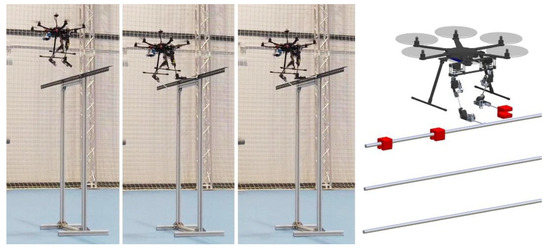
Figure 1.
Dual arm aerial manipulation robot grabbed a linear structure with the right (grabbing) arm.
The innovative aspects of this paper with respect to our previous published works [17,21,22] can be summarized in the following points:
- The development and testing of a new functionality for the dual arm aerial manipulator: estimating the position of the robot relative to the grabbing point with one of the arms while the other is intended to conduct the operation on flight.
- The evaluation of the positioning accuracy in the estimation provided by the grabbing arm compared to the ground truth given by an Opti-Track system.
- The combination of passive (mechanical) and active (control) compliance methods in the grabbing arm to facilitate the accommodation of the aerial robot to sustained grabbing forces.
- The experimental evaluation and qualitative analysis of the effects of the grabbing arm and the injected disturbances over the stability of the multirotor controller.
The rest of the paper is organized as follows. The prototype employed in the experiments is firstly described in Section 2. Section 3 covers the kinematics and position estimation, with the mentioned control methods described in Section 4. The experimental results are presented in Section 5, and the conclusions are summarized in Section 6.
2. System Description
2.1. Compliant Dual Arm
The manipulator used for validating the methods described in Section 4 is a lightweight and compliant dual arm system developed at the GRVC Robotics Labs. A picture of the arms can be seen in Figure 2, indicating in Table 1 its main features. Each arm provides three degrees of freedom for end effector positioning in the following kinematic configuration [22]: shoulder yaw at the base (), shoulder pitch (), and elbow pitch (). The arms are built with the Herkulex DRS-0201 smart servos, and a customized frame structure manufactured in carbon fiber and aluminum, providing full servo protection at the shoulder yaw joint with a pair of polymer bearings, and partial servo protection in the other two joints [21]. In order to estimate and control the torques and forces, the grabbing arm (right arm) integrates 14-bit resolution magnetic encoders that are interfaced through a STM32F303 microcontroller board, sending the deflection measurement to the main computer at 200 Hz with 1 ms latency. Each of the arms and the sensors are connected to the Raspberry Pi 3B+ through USB-to-USART interfaces, where control program of the arms is executed. The manipulator is fed with a 2S, 650 mAh LiPo battery, providing an operation time of around 20 min.
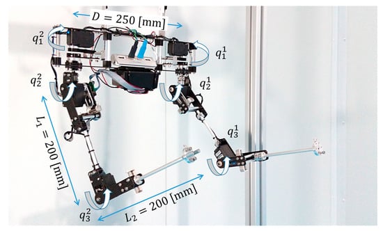
Figure 2.
Compliant dual arm used in the experiments.

Table 1.
Main features of the lightweight and compliant dual arm.
The tip of the forearm link includes an aluminum flange to facilitate the integration of the end effector in the manipulator. For safety reasons, the grabbing operation is conducted with a magnetic gripper (around 5 N force), using the linear metallic structure shown in Figure 1 for grabbing.
2.2. Aerial Manipulation Robot
The dual arm system is integrated in an S550 platform, a hexarotor similar to a DJI F550. This is equipped with six DJI 2312E brushless motors with 9 × 4.5 inch propellers. Figure 3 shows a picture of the aerial robot, identifying its components, including the Pixhawk 2.1 autopilot, the Raspberry Pi 3B+ computer board, and the 4S 4400 mAh LiPo battery (0.5 kg) used as counterweight of the arms. The setup is similar to the one described in [14], constraining the motion of the arms to prevent the collision with the landing gear. The hardware and software architecture of the system is represented in Figure 4. The control program of the arms, developed in C/C++, as well as the different software modules that control the aerial platform, based on ROS and the UAV Abstraction Layer [24], are executed in the Raspberry Pi and interfaced by the Ground Control Station (GCS) through the wireless link. Four USB-to-USART devices are connected to the computer board: (1) the Pixhawk autopilot, (2) the left arm, (3) the right arm, and (4) the microcontroller board that reads the sensors. The position and orientation of the multirotor are obtained from an Opti Track system, used as ground truth.
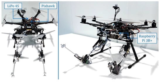
Figure 3.
Dual arm aerial manipulation robot.
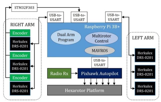
Figure 4.
Hardware architecture of the aerial manipulation robot.
3. Modelling
3.1. Kinematics
As usual, three reference frames are defined for the aerial manipulation system, as illustrated in Figure 5: the Earth fixed frame (inertial), the multirotor body frame , and the manipulator frame , with for the left/right arms. In the following, denotes the position of a certain point w.r.t. (with respect to) reference frame . In this way, and represent the multirotor position and orientation relative to , and is the position of the tool center point (TCP) of the -th manipulator expressed in its own frame. The origin of is located at the intersection of the shoulder joints, with the x-axis pointing forwards, the y-axis parallel to the baseline of the two arms, and the z-axis pointing upwards.
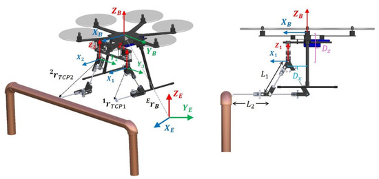
Figure 5.
Kinematic model of the dual arm aerial manipulator.
The three reference frames are related through the corresponding transformation matrices:
where is the multirotor rotation matrix; is the origin of relative to , with and being the displacement of the arms with respect to in the x- and z-axes, respectively; and is the separation distance between the arms in the y-axis.
The arms implement the 3-DOF (degrees of freedom) configuration considered in our previous work [14,22], with three joints for TCP positioning: shoulder yaw (base), shoulder pitch, and elbow pitch. The wrist joints are not considered due to the convenience to simplify the mechanical construction and reduce the weight of the arms. The rotation angle of the -th joint of the -th arm is denoted as , whereas is the corresponding servo shaft position. The difference between these two variables is the deflection angle, , measured by the encoders [17,21]. The forward and inverse kinematic models are computed as follows (superscript is omitted for clarity reasons):
where and are the upper arm/forearm link lengths, and is given by
3.2. Relative Position Estimation
If the end effector of the grabbing arm is firmly attached to a fixed point, then it is possible to estimate the position of the multirotor relative to this grabbing point just applying the homogeneous transformation from to , taking into account that the position of the TCP referred to is directly obtained from the forward kinematic model given by Equation . The accuracy in the position estimation can be obtained multiplying the joint position error (including the deflection error) by the Jacobian of the arm. The wrist joints are not essential for this purpose, as the multirotor orientation can be obtained from the inertial measurement unit (IMU) of the aerial platform. However, a certain level of accommodation is required at the wrist so the robotic arm can follow the position and orientation deviations of the aerial platform while it is grabbed.
Two similar mechanisms have been proposed in previous works for estimating the pose of an aerial manipulator relative to a contact point. Reference [12] presents a docking tool consisting of an articulated arm with passive joints that is deployed over a pipe with a stiff-joint dual arm, whereas reference [25] relies on a passive spherical wrist joint and an IMU integrated at the end effector of a 3-DOF arm. In this paper, we combine the passive/active compliance methods for estimating the multirotor position while controlling the interaction force.
3.3. Dynamics
The dynamic model of the compliant joint dual arm aerial manipulation robot is derived from the Lagrangian and the generalized equations of the forces and torques:
where is the Lagrangian; and are the kinetic and potential energies, respectively; is the vector of generalized coordinates; and and respectively represent the generated and external wrenches acting on the aerial robot. The vector of generalized coordinates includes the multirotor position and orientation, as well as the servo shaft and output link angular position vectors, and , respectively, and thus is defined as follows.
Analogously, the vector of generalized forces comprises the forces and torques acting over the multirotor and the joints of the manipulator.
The vector of external forces models the disturbance wrenches exerted on the multirotor base [18,19,20], the contact forces at the end effector [4,6,17], as well as the aerodynamic forces raised when the thrust of the rotors is affected by close surfaces in the environment [7,26].
The kinetic energy of the aerial manipulator can be expressed as the sum of the kinetic energy of the aerial platform and the kinetic energy of the robotic arms:
Each of these components comprises two terms corresponding to the translation and rotation of the masses with respect to the inertial frame :
where and are the mass and inertia tensor of the aerial platform, respectively, whereas and are mass and inertia of the -th joint of the -th arm, respectively. The potential energy of the aerial manipulator also includes two terms, the gravity and elastic potential of the compliant joints:
Here, is the gravity constant, and is the corresponding joint stiffness. After some work, it is possible to express the dynamic model in the usual compact matrix form [14]:
where is the generalized inertia matrix; and represent the centrifugal, Coriolis, and gravity terms; and and correspond to the stiffness and damping terms of the compliant manipulator, respectively [17]. The dynamic coupling between the arms and the aerial platform is associated with the cross terms in the generalized inertia matrix, which can be decomposed in three groups of submatrices identified in [14]: multirotor translation (decoupled from rotation), multirotor rotation with coupling terms, and dual arm manipulator with coupling terms. Since the grabbing arm will be held to a fixed point, the corresponding inertia, Coriolis, and gravity terms will be negligible compared to the operation arm. Moreover, if the sensitivity of the zero-torque controller described in next section is good enough, then the magnitude of the wrenches associated to the stiffness and damping terms will be relatively low, and with it, the influence over the multirotor controller.
As stated in the introduction and illustrated in Figure 1, the operation arm is intended to perform the manipulation operation (the installation of a bird flight diverter) while the grabbing arm provides the position estimation. This can be assimilated to a close kinematic chain [27,28] with floating base [29], in which the pushing/pulling force exerted by the operation arm will cause a reaction torque on the aerial platform that should be cancelled by the multirotor controller with the help of the grabbing arm in order to prevent undesired position deviations. This motivates the implementation of an active impedance control scheme with the grabbing arm, as explained below.
4. Control
4.1. Definition of the Control Task
As stated in the introduction, a dual arm system allows the realization of aerial manipulation tasks in grabbing conditions, using one arm for grabbing and for estimating the position of the aerial platform relative to the grabbing point (Section 3.2), whereas the other takes care of conducting the task, for example, the installation of a sensor device [21]. Since the grabbing arm is actuated and mechanically compliant, it is possible to estimate and control the forces and torques acting over the manipulator from the deflection of the joints [17,21]. The idea is that the arm helps the multirotor to reach the desired position when it is disturbed by an external force, exerting a pushing/pulling force in the opposite direction of the position error, as Figure 6 illustrates.
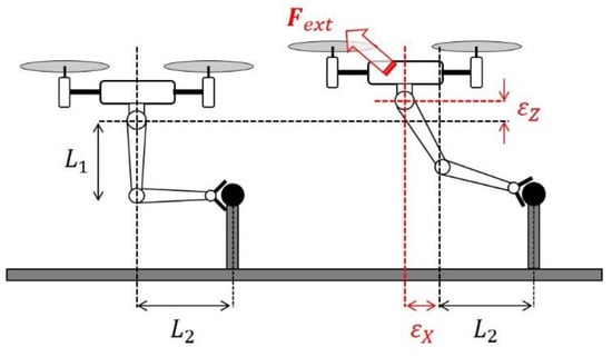
Figure 6.
Model considered in grabbing conditions. Nominal operation pose (left), and displacement due to external force (right). The grabbing arm compensates the disturbance exerting a reaction force.
Therefore, the grabbing arm can be used in two ways:
- As relative position sensor, with zero torque control, so the reaction wrenches induced over the multirotor are relatively small.
- As an active impedance link, exerting a controlled force over the aerial platform to compensate external forces and guide the multirotor towards the reference position.
In the first case, the joints of the grabbing arm implement a PI (proportional-integral) controller to maintain a zero deflection (torque) reference, acting over the servo position as follows:
Here, is the position of the -th servo of the right arm, whereas the term on the right side is the incremental position correction. The proportional and integral gains, and , can be tuned experimentally, taking into account the nominal values of the deflection (≈5 degrees). Now, we impose that the nominal operation position of the aerial robot relative to the grabbing point is the L-shaped configuration of the arm, since this is far enough from the joint limits and the kinematic singularities (although any other could be considered):
The position deviation of the aerial platform is then defined as the displacement of the TCP of the grabbing arm w.r.t. the reference position. That is,
Note that the maximum deviation is limited by the reach of the arm, . If the influence of the grabbing arm over the attitude controller is relatively low due to the zero-torque controller, this measurement can then be taken as input by the position controller of the multirotor platform, as represented in upper part of Figure 7, replacing the GPS (Global Positioning System) used for navigating to achieve better accuracy during the manipulation phase.
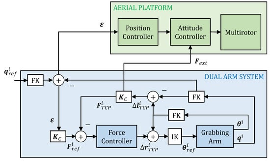
Figure 7.
Control scheme of the aerial manipulator with grabbing arm ().
4.2. Impedance Control in Grabbing Conditions
Assuming that the aerial platform is close to the hover state during the grabbing maneuver (), it is desired that the position deviation of the aerial platform is assimilated to an impedance behavior characterized as follows:
where , , and are the desired inertia, damping, and stiffness, respectively, and is the external force exerted over the multi-rotor. This force can be estimated from the Cartesian deflection of the grabbing arm, as it will be seen in next subsection, and taken as input by the attitude controller of the aerial platform so it can be partially compensated with the wrenches generated by the rotors.
The grabbing arm will react to the external force exerting a pushing/pulling force at the end effector in the direction of the position deviation, relying on the Cartesian force controller described in the next subsection. The impedance control is then achieved, generating a force reference that cancels the dynamic behavior described by Equation . Figure 7 represents the case of desired stiffness, .
4.3. Force Control Based on Cartesian Deflection
The force control of the compliant arm is formulated in the Cartesian space and based on the Cartesian deflection, defined as the position deviation of the TCP of the compliant arm w.r.t. the same point in an equivalent stiff joint arm. That is,
This definition is useful for expressing the force at the end effector directly in the task space:
where and are the Cartesian stiffness and damping matrices, respectively, whose values can be obtained from the physical joint stiffness and damping through the Jacobian:
where is the physical joint stiffness matrix [17]. The Cartesian damping can be obtained analogously. The force controller, represented in Figure 7 relies on the inverse kinematics, giving as output an incremental position correction term for the TCP:
Here, is the position increment that should be applied in the grabbing arm to achieve the desired force reference; is the force control error at the TCP; whereas and are the proportional and integral gain matrices, respectively, whose value is tuned experimentally knowing the nominal values of the forces (around ) and the Cartesian deflection (around ).
5. Experimental Results
5.1. Position Estimation with Zero Deflection/Torque Control
The goal of this experiment was to evaluate the accuracy of the position estimation provided by the grabbing arm when this was used as position sensor, enabling the zero-torque controller to reduce the reaction wrenches induced over the aerial platform on flight (see Section 4.1). The experiment, shown in the video provided as Supplementary Material, consisted of four phases:
- (1)
- The multirotor takes off.
- (2)
- The arms adopt the nominal operation pose given by Equation .
- (3)
- The aerial robot approaches the contact point using the Opti Track system for navigating.
- (4)
- Once the arm grabs the support structure, the zero-torque controller and the estimator are enabled while the multirotor is controlled in position with the Opti Track system.
Figure 8, Figure 9 and Figure 10 represent the signals of interest during the grabbing maneuver, that is, the multirotor position (arm estimation and ground truth) relative to the nominal pose, the multirotor orientation, the estimation error, and the joint position and torque in the grabbing arm. In order to appreciate the ability of accommodation of the arm and the accuracy in the estimation, we intentionally deviated the aerial platform in the x- and z-axes, with small deviations in the y-axis. Note that in the experiments the end-effector is supposed to be firmly attached to the grabbing point in such a way that the displacement of the multirotor platform will force the displacement of the grabbing arm. However, the magnetic gripper may slip around the contact area, introducing errors in the position estimation. It was also assumed that the multirotor heading (yaw angle) was almost constant, with the -axis parallel to the linear structure. Otherwise, additional degrees of freedom should be integrated in the wrist joint to estimate the relative orientation, although this is out of the scope of this work. The influence of these two effects over the positioning accuracy can be observed in Figure 9, where the estimation error increased as the multirotor orientation in the yaw angle changed with respect to its initial value, causing mainly errors in the y-axis estimation.
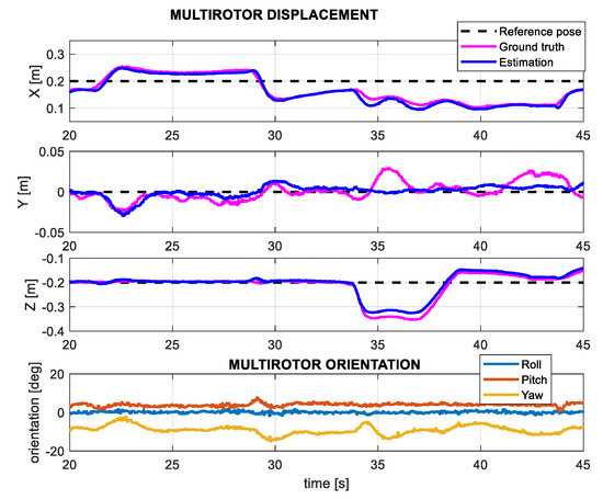
Figure 8.
Multirotor displacement in the grabbing maneuver with zero torque control. Nominal pose (black), displacement measured by OptiTrack (magenta), and arm estimation (blue).
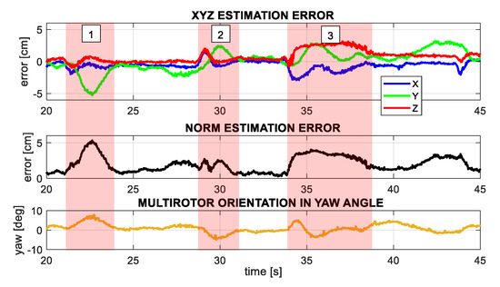
Figure 9.
Position estimation error, using Opti-Track as ground truth. x-, y-, and z-axes error (up) and error norm (middle). The three shaded areas correspond to situations in which the platform is rotated in yaw and the error increased since the magnetic gripper was not firmly attached to the point.
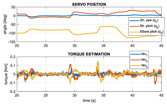
Figure 10.
Evolution of the servo position and torque estimation during the grabbing maneuver.
5.2. Impedance Control in Test-Bench
Before its evaluation on flight, the impedance controller of the grabbing arm was firstly validated in test-bench in order to evidence more clearly the variation in the desired stiffness, as defined in Equation . During the experiment, the arm adopted the L-shaped configuration (Figure 6 and Equation ), manually exerting an external force at the end effector that was estimated and compensated from the Cartesian deflection, as expressed by Equations and . The desired stiffness was set to for the experiment illustrated in Figure 11, and to for the experiment represented in Figure 12. As it can be seen, the position deviation of the end effector was lower in the second case, as expected, and the instantaneous stiffness () was similar to the desired value. Note that the stiffness is affected by the singularity associated to the deflection when this tends to zero.
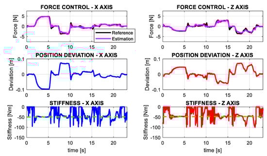
Figure 11.
Force reference and estimation (up), position deviation (middle), and instantaneous stiffness (down) in the x- and z-axes for a desired stiffness .
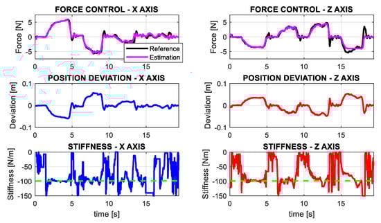
Figure 12.
Force reference estimation (up), position deviation (middle), and instantaneous stiffness (down) in the x- and z-axes for a desired stiffness .
5.3. Grabbing Interaction on Flight with Impedance Control
The goal of this experiment was to analyze the behavior of the aerial manipulation robot on flight when the grabbing arm was actively controlling the impedance in the x- and z-axes, considering a desired Cartesian stiffness . The performance of the controller was evaluated by injecting a disturbance on the multirotor position that emulates the effect of an external force, such as a wind gust. The zero-torque controller of the first joint (shoulder yaw) was disabled, relying only on the passive compliance to support the lateral displacements (y-axis) and heading variations (yaw angle) of the multirotor. The flight test consists of eight phases:
- The aerial manipulator takes off with the arms resting in landing configuration.
- The grabbing arm adopts the nominal pose (L-shaped) while the operation arm is retracted.
- The impedance controller is enabled, imposing a zero reference for the first joint ().
- The aerial manipulator approaches to the linear structure until the magnetic gripper grabs it.
- The aerial manipulator hovers while the impedance controller of the grabbing arm is active.
- A position disturbance is injected through the radio controller to observe the response of the aerial manipulator and the reaction of the grabbing arm.
- The torque control of the servos is disabled to release the grabbing arm.
- The arms adopt the landing pose, and the platform goes back and lands.
Figure 13 and Figure 14 show the evolution of the system in the time intervals corresponding to phase 5 and phase 6, respectively. On the one hand, Figure 13 covers the time interval from t = 25 to t = 35 s, in which the multirotor was hovering at fixed position while the grabbing arm exerted a small force in the x-axis, around 0.5 N, due to the slight displacement of the platform with respect to the nominal pose. On the other hand, Figure 14 covers the interval from t = 48 to t = 70 s. At t = 49.6 [s], we intentionally applied a 10 cm displacement in the x-axis position of the multirotor, emulating a wind gust. The grabbing arm reacted, exerting a pushing force with a peak of 2.2 [N] that counteracted the disturbance, recovering the nominal operation pose in 2 s. The instantaneous stiffness varied w.r.t. the desired value (50 N/m) due to the singularity in the displacement (). Note also that, since the grabbing arm was not aligned with the plane of the base but it was displaced a distance (see Section 3.1), then the force exerted during the interaction would cause a reaction torque in the yaw angle of the multirotor, and with it, a position deviation in the y-axis, as can be seen in Figure 14. The effect was accentuated as the pilot disturbed the multirotor controller between t = 52 and t = 60 s. Although the passive deflection of the shoulder yaw joint provided a certain level of accommodation, the motion constraint associated with the grabbing condition had a more significant effect on the y-axis and yaw angle, in accordance with the results shown in Figure 9.
Figure 13.
Evolution of the grabbing arm while the multirotor hovers with no disturbance during the grabbing maneuver (phase 5) with impedance control in the x- and z-axes ().
Figure 14.
Evolution of the grabbing arm and the multirotor, disturbed at t = 49.6 seconds, during the grabbing maneuver (phase 6) with impedance control in the x- and z-axes ().
6. Conclusions
The paper presented two approaches for the estimation and control of the physical interactions of a compliant dual arm aerial manipulation robot operating in grabbing conditions, in which one of the arms was used as position sensor relative to a grabbing point, implementing a zero-torque controller so the wrenches induced over the multirotor base were relatively low. The mechanical joint compliance of the arm was also exploited for the development of active compliance methods, achieving desired impedance behaviors that improved the response of the aerial manipulator when it was affected by external disturbances while interacting physically with the environment. The experimental results presented here validated the concepts, allowed us to evaluate the accuracy of the position estimation, and evidenced the convenience of combining the passive/active compliance on the three Cartesian axes.
Although the aerial manipulation robot will require a navigation system to reach the workspace, the positioning accuracy required to perform the manipulation task (which should be around 10% of the reach of the arm) cannot be achieved with typical sensors employed in outdoor environments, such as GPS, LIDAR (light detecting and ranging), or vision systems. In this sense, the estimation methods described in this work result from special interest to avoid the integration of additional positioning systems, taking into account the limited payload capacity of the aerial platform, being also an effective and reliable solution. In terms of future work, we propose the application of this system for the installation of bird flight diverters on power lines, or for inspection and maintenance of railways, chemical plants, and other linear infrastructure.
Supplementary Materials
The following are available online at https://www.mdpi.com/2076-3417/10/24/8927/s1. Video S1: Aerial_Physical_Interaction.mp4.
Author Contributions
Conceptualization, A.O. and A.S.; software, A.S. and P.J.S.-C.; validation, A.S. and P.J.S.-C.; data curation, A.S.; writing—original draft preparation, A.S.; writing—review and editing, G.H. and A.S.; supervision, G.H.; project administration, A.O.; funding acquisition, A.O. All authors have read and agreed to the published version of the manuscript.
Funding
This work was funded by the AERIAL-CORE project (H2020-2019-871479) funded by the European Commission; the European Research Council Advanced Grant GRIFFIN project (Action 788247); and the ARM-EXTEND (DPI2017-89790-R) and ARTIC (RTI2018-102224-B-I00) projects funded by the Spanish Ministerio de Economia, Industria, y Competitividad.
Conflicts of Interest
The authors declare no conflict of interest.
References
- Suarez, A.; Vega, V.M.; Fernandez, M.; Heredia, G.; Ollero, A. Benchmarks for Aerial Manipulation. IEEE Robot. Autom. Lett. 2020, 5, 2650–2657. [Google Scholar] [CrossRef]
- Kim, S.; Choi, S.; Kim, H.J. Aerial manipulation using a quadrotor with a two DOF robotic arm. In Proceedings of the IEEE/RSJ International Conference on Intelligent Robots and Systems, Tokyo, Japan, 3–7 November 2013; pp. 4990–4995. [Google Scholar]
- Orsag, M.; Korpela, C.; Bogdan, S.; Oh, P. Dexterous aerial robots—Mobile manipulation using unmanned aerial systems. IEEE Trans. Robot. 2017, 33, 1453–1466. [Google Scholar] [CrossRef]
- Cataldi, E.; Muscio, G.; Trujillo, M.A.; Rodriguez, Y.; Pierri, F.; Antonelli, G.; Caccavale, F.; Viguria, A.; Chiaverini, S.; Ollero, A. Impedance control of an aerial-manipulator: Preliminary results. In Proceedings of the 2016 IEEE/RSJ International Conference on Intelligent Robots and Systems (IROS), Daejeon, Korea, 9–14 October 2016; pp. 3848–3853. [Google Scholar]
- Santamaria-Navarro, A.; Grosch, P.; Lippiello, V.; Solà, J.; Andrade-Cetto, J. Uncalibrated visual servo for unmanned aerial manipulation. Trans. Mechatron. 2017, 22, 1610–1621. [Google Scholar] [CrossRef]
- Tognon, M.; Chavez, H.A.T.; Gasparin, E.; Sable, Q.; Bicego, D.; Mallet, A.; Lany, M.; Santi, G.; Revaz, B.; Cortess, J.; et al. A truly-redundant aerial manipulator system with application to push-and-slide inspection in industrial plants. IEEE Robot. Autom. Lett. 2019, 4, 1846–1851. [Google Scholar] [CrossRef]
- Jimenez-Cano, A.E.; Sanchez-Cuevas, P.J.; Grau, P.; Ollero, A.; Heredia, G. Contact-based bridge inspection multirotors: Design, modeling, and control considering the ceiling effect. IEEE Robot. Autom. Lett. 2019, 4, 3561–3568. [Google Scholar] [CrossRef]
- Rhudy, M.B.; Chao, H.; Gu, Y. Wide-field optical flow aided inertial navigation for unmanned aerial vehicles. In Proceedings of the IEEE/RSJ Int. Conference on Intelligent Robots and Systems, Chicago, IL, USA, 14–18 September 2014; pp. 674–679. [Google Scholar]
- Schmid, K.; Tomic, T.; Ruess, F.; Hirschmüller, H.; Suppa, M. Stereo vision based indoor/outdoor navigation for flying robots. In Proceedings of the 2013 IEEE/RSJ International Conference on Intelligent Robots and Systems, Tokyo, Japan, 3–7 November 2013; pp. 3955–3962. [Google Scholar]
- Faessler, M.; Fontana, F.; Forster, C.; Mueggler, E.; Pizzoli, M.; Scaramuzza, D. Autonomous, vision-based flight and live dense 3D mapping with a quadrotor micro aerial vehicle. J. Field Robot. 2016, 33, 431–450. [Google Scholar] [CrossRef]
- Huh, S.; Shim, D.H.; Kim, J. Integrated navigation system using camera and gimbaled laser scanner for indoor and outdoor autonomous flight of UAVs. In Proceedings of the IEEE/ International Conference on Intelligent Robots and Systems, Tokyo, Japan, 3–7 November 2013; pp. 3158–3163. [Google Scholar]
- Ramon Soria, P.; Arrue, B.C.; Ollero, A. A 3D-printable docking system for aerial robots: Controlling aerial robotic manipulators in outdoor industrial applications. IEEE Robot. Autom. Mag. 2019, 26, 44–53. [Google Scholar] [CrossRef]
- Ruggiero, F.; Trujillo, M.A.; Cano, R.; Ascorbe, H.; Viguria, A.; Perez, C.; Lippiello, V.; Ollero, A.; Siciliano, B. A multilayer control for multirotor UAVs equipped with a servo robot arm. In Proceedings of the IEEE Int. Conference on Robotics and Automation (ICRA), Seattle, WA, USA, 26–30 May 2015; pp. 4014–4020. [Google Scholar]
- Suarez, A.; Jimenez-Cano, A.E.; Vega, V.M.; Heredia, G.; Rodriguez-Castaño, A.; Ollero, A. Design of a lightweight dual arm system for aerial manipulation. Mechatronics 2018, 50, 30–44. [Google Scholar] [CrossRef]
- Fumagalli, M.; Naldi, R.; Macchelli, A.; Forte, F.; Keemink, A.Q.L.; Stramigioli, S.; Carloni, R.; Marconi, L. Developing an aerial manipulator prototype: Physical interaction with the environment. IEEE Robot. Autom. Mag. 2014, 21, 41–50. [Google Scholar] [CrossRef]
- Hamaza, S.; Georgilas, I.; Fernandez, M.; Sanchez, P.; Richardson, T.; Heredia, G.; Ollero, A. Sensor installation and retrieval operations using an unmanned aerial manipulator. IEEE Robot. Autom. Lett. 2019, 4, 2793–2800. [Google Scholar] [CrossRef]
- Suarez, A.; Heredia, G.; Ollero, A. Physical-virtual impedance control in ultralightweight and compliant dual-arm aerial manipulators. IEEE Robot. Autom. Lett. 2018, 3, 2553–2560. [Google Scholar] [CrossRef]
- Bodie, K.; Brunner, M.; Pantic, M.; Walser, S.; Pfändler, P.; Angst, U.; Siegwart, R.; Nieto, J. An omnidirectional aerial manipulation platform for contact-based inspection. In Proceedings of Robotics: Science and Systems. arXiv 2019, arXiv:1905.03502. [Google Scholar]
- Ruggiero, F.; Cacace, J.; Sadeghian, H.; Lippiello, V. Impedance control of VToL UAVs with a momentum-based external generalized forces estimator. In Proceedings of the IEEE International Conference on Robotics and Automation (ICRA), Hong Kong, China, 31 May–7 June 2014; pp. 2093–2099. [Google Scholar]
- Tomić, T.; Haddadin, S. A unified framework for external wrench estimation, interaction control and collision reflexes for flying robots. In Proceedings of the IEEE/RSJ International Conference on Intelligent Robots and Systems, Chicago, IL, USA, 14–18 September 2014; pp. 4197–4204. [Google Scholar]
- Suarez, A.; Real, F.; Vega, V.M.; Heredia, G.; Rodriguez-Castaño, A.; Ollero, A. Compliant bimanual aerial manipulation: Standard and long reach configurations. IEEE Access 2020, 8, 88844–88865. [Google Scholar] [CrossRef]
- Suarez, A.; Heredia, G.; Ollero, A. Lightweight compliant arm with compliant finger for aerial manipulation and inspection. In Proceedings of the IEEE/RSJ International Conference on Intelligent Robots and Systems (IROS), Daejeon, Korea, 9–14 October 2016; pp. 4449–4454. [Google Scholar]
- AERIAL-CORE Project Home Page. Available online: https://aerial-core.eu/ (accessed on 12 October 2020).
- Real, F.; Torres-González, A.; Ramon-Soria, P.; Capitan, J.; Ollero, A. UAL: An abstraction layer for unmanned aerial vehicles. In Proceedings of the 2nd International Symposium on Aerial Robotics, Philadelphia, PA, USA, 11–12 June 2018. [Google Scholar]
- Perez-Jimenez, M.; Montes-Grova, M.A.; Ramon-Soria, P.; Arrue, B.C.; Ollero, A. POSITRON: Lightweight active positioning compliant joints robotic arm in power lines inspection. In Proceedings of the 2020 International Conference on Unmanned Aircraft Systems (ICUAS), Athens, Greece, 1–4 September 2020; pp. 729–736. [Google Scholar]
- Sanchez-Cuevas, P.J.; Heredia, G.; Ollero, A. Characterization of the aerodynamic ground effect and its influence in multirotor control. Int. J. Aerosp. Eng. 2017, 2017, 1823056. [Google Scholar] [CrossRef]
- Liu, T.; Lei, Y.; Han, L.; Xu, W.; Zou, H. Coordinated resolved motion control of dual-arm manipulators with closed chain. Int. J. Adv. Robot. Syst. 2016, 13, 80. [Google Scholar] [CrossRef]
- Lee, J.; Chang, P.H.; Jamisola, R.S. Relative impedance control of dual-arm robots performing asymmetric bimanual tasks. Trans. Ind. Electron. 2014, 61, 3786–3796. [Google Scholar] [CrossRef]
- Stolfi, A.; Gasbarri, P.; Sabatini, M. A combined impedance-PD approach for controlling a dual-arm space manipulator in the capture of a non-cooperative target. Acta Astronaut. 2017, 139, 243–253. [Google Scholar] [CrossRef]
Publisher’s Note: MDPI stays neutral with regard to jurisdictional claims in published maps and institutional affiliations. |
© 2020 by the authors. Licensee MDPI, Basel, Switzerland. This article is an open access article distributed under the terms and conditions of the Creative Commons Attribution (CC BY) license (http://creativecommons.org/licenses/by/4.0/).