Abstract
Digital Twins have been in the focus of research in recent years, trying to achieve the vision of Industry 4.0. In the domain of industrial energy systems, they are applied to facilitate a flexible and optimized operation. With the help of Digital Twins, the industry can participate even stronger in the ongoing renewable energy transition. Current Digital Twin implementations are often application-specific solutions without general architectural concepts and their structures and namings differ, although the basic concepts are quite similar. For this reason, we analyzed concepts, architectures, and frameworks for Digital Twins in the literature to develop a technology-independent Generic Digital Twin Architecture (GDTA), which is aligned with the information technology layers of the Reference Architecture Model Industry 4.0 (RAMI4.0). This alignment facilitates a common naming and understanding of the proposed architectural structure. A proof-of-concept shows the application of Semantic Web technologies for instantiating the proposed GDTA for a use case of a Packed-Bed Thermal Energy Storage (PBTES).
1. Introduction
1.1. Motivation
Digitalization is changing the way business is conducted within industrial value chains, facilitated by the rapid development of communication and information technology [1]. This process is also referred to as the fourth industrial revolution or Industry 4.0. The goal is a highly optimized and customized production, as well as enhanced automation and adaption capabilities [2]. To realize these visions of Industry 4.0, the Digital Twin (DT) is one of the most promising enabling technologies [3].
Industry 4.0 and the sustainable energy transition share important characteristics and can mutually benefit from each other [4]. Information and communication technology helps to increase energy efficiency and the interaction of industry with smart grids which facilitates the integration of renewable energy sources. DTs are also the key enabler for such applications, as their common functionality includes monitoring, diagnostic, prediction, and control [5].
The concepts and capabilities of DTs are not clearly defined and sometimes hard to grasp. This is caused by the fact that DTs can be applied for various tasks in different life-cycle phases and industrial domains. Thus, different interpretations of a DT exist, driven by specific use cases. This leads to the problem that concrete realizations of DTs follow a concrete goal without any architectural template [6]. For this reason, we present a novel generic architecture for a DT, which is in line with the Reference Architecture Model Industry 4.0 (RAMI 4.0), called Generic Digital Twin Architecture (GDTA). The GDTA facilitates a technology independent implementation of DTs and gives orientation for locating existing frameworks and technologies inside this architectural model. We also introduce a context-dependent View on the Virtual Entity inside the DT, consisting of special-purpose simulation models in combination with context information. Additionally, a prototypical implementation of the proposed GDTA is presented as a proof-of-concept, using Semantic Web technologies. It demonstrates how the context information of resources and services can be managed inside a DT, and how a View of the Virtual Entity can be based on a Simulation Service.
The remainder of the paper is structured as follows: Section 1.2 gives a short overview of related work in the area of DT concepts, frameworks, and reference architectures. Section 2 describes the methods which are applied for carrying out the presented work. Afterward, the GDTA is introduced in Section 3. The proposed architecture is used for our proof-of-concept implementation, based on Semantic Web technologies and applied for a use case of a thermal energy storage system in Section 4. In the end, the presented GDTA is discussed with respect to other DT architectural frameworks, and an outlook on our future work is given.
1.2. Related Work
In general, a DT can be defined as “a formal digital representation of some asset, process or system that captures attributes and behaviors of that entity suitable for communication, storage, interpretation or processing within a certain context” [7].
A very basic concept for structuring a DT defines three different aspects: the physical space, the virtual space, and the connection between them to exchange data and information [8]. A similar concept is known from the industrial domain as Cyber–Physical System (CPS) or more specifically as Cyber–Physical Production System (CPPS). In [9], CPSs are described as autonomous and cooperative elements and sub-systems across all levels of production, able to communicate with each other in situation-dependent ways. The goal of CPSs is to have elements that can acquire and process data, allowing them to self-control certain tasks and interact with humans. To reach that goal, a certain kind of virtual representation of the production system has to be available. Therefore, a CPS can be characterized by a physical asset and its cyber counterpart, which means that a DT can be seen as only the digital model inside a CPS [5]. Conversely, this also implies that a DT is the prerequisite for a CPS [10].
For CPSs, a five layer architecture (5C architecture) was proposed in [11], defining a “Smart Connection Level”, “Data-to-Information Conversion Level”, “Cyber Level”, “Cognition Level”, and “Configuration Level”. These layers should help to develop and implement CPSs at a certain layer of this 5C architecture. In this context, the Smart Connection Level has to deal with acquiring accurate and reliable data from the physical entity and is the first step to create a CPS. Afterward, meaningful information is inferred from the data at the Data-to-Information Conversion Level. This level brings self-awareness to the machines. The Cyber Level acts as an information hub inside the 5C architecture, which also introduces the possibility of self-comparison of the performance of machines. In-depth knowledge of the monitored system is created at the Cognition Level. Expert users will be supported by this information to make the correct decision. At the Configuration Level, feedback is given from the cyber-space to the physical space. Here, the supervisory control resides and makes machines self-configurable and self-adaptive. This functional view of a CPS can also be beneficial for designing and implementing a DT for certain applications. Typical applications have been identified by a literature review in [12] and can be clustered in the following categories: simulation and optimization, monitoring, diagnosis, and prediction.
Another important concept for describing DTs is the so-called Five-Dimensional Digital Twin (5D-DT) [13]. It is an evolution of the previously mentioned DT concept, which extends the three dimensions (“Physical Entity”, “Virtual Entity”, “Connection”) by the data aspect as well as the service aspect. These five dimensions and their relations are shown in Figure 1. The “Physical Entity” consists of various subsystems that perform specific tasks, facilitated with different sensors that collect the states and working parameters. The “Virtual Entity” aims to model the physical entity with high precision by the integration of multiple different types of models such as geometry models, physical models, behavior models, and rule models. The “Service Model” includes services for the “Physical Entity” and the “Virtual Entity”. It optimizes the operations of the “Physical Entity” and ensures the high fidelity of the “Virtual Entity” through calibration of the “Virtual Entity” parameters during run-time. The “Data Model” consists of five parts: data from the physical entity, data from the virtual entity, data from the services, domain knowledge, and the fusion of those data. The “Connection Model” describes each connection between the components of the DT. The ideas of the 5D-DT concept are the foundation for our proposed GDTA.
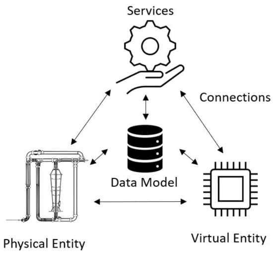
Figure 1.
Five dimensions of the Five-Dimensional Digital Twin (5D-DT) concept adapted from [13].
In addition to these very general concepts with a high level of abstraction, more detailed architectural concepts and frameworks have been proposed for the implementation of DTs. In the following paragraph, an overview of these concepts is given and summarized in Table 1. Table 1 also gives a classification based on their level of abstraction. A high level of abstraction means that a more general concept is presented, whereas a low level indicates a more concrete architecture or framework, targeting the implementation of a DT. They are also used in the discussion (Section 5) to set our proposed GDTA into perspective by comparing it with these concepts.

Table 1.
Overview of concepts, architectures, and frameworks for Digital Twins (DT).
“Intelligent Digital Twin”—In [14], an architecture for an “Intelligent Digital Twin” was proposed by applying algorithms known from Artificial Intelligence (AI). Next to the data acquisition interface, a synchronization interface is introduced to keep the simulation models of the DT in line with the physical asset, as they can otherwise differ over its life-cyle. Also, a co-simulation interface is described as a component of the architecture to enable communication with other DTs and to facilitate multidisciplinary co-simulation.
“Reference Framework for Digital Twins”—A reference framework for DTs in the context of the 5C architecture of CPS is presented in [6]. The main building blocks of DTs, including their properties (structure and interrelation), were specified for the proposed framework. Therefore, a systematic literature review was conducted followed by a framework analysis using grounded theory. They identified four main building blocks of a DT which are: a “Physical Entity Platform”, a “Virtual Entity Platform”, a “Data Management Platform”, and a “Service Platform”. They also identified three different types of physical entities, namely the “Physical Objects”, “Physical Nodes”, and “Humans”. The “Virtual Entity Platform” consists of many virtual entity models, including information to mirror a certain aspect of the physical entity. It is responsible for the generation and maintenance of “Semantic Models” (geometric models, physical models, behavioral models, rule models, process models) of the physical entity to create its virtual representation. The “Data Management Platform” performs data acquisition, management (collection, transmission, storage, integration, processing, cleaning, analysis, data mining and information extraction), and storage. The “Service Platform” consists of service models and a service management layer to organize services for concrete applications.
“Cognitive Twin Toolbox”—In [15], a conceptual architecture of the Cognitive Twin Toolbox (COGNITWIN) is presented with a special focus on the process industry. Three levels of twins were defined: A “Digital Twin” which only uses isolated models of the physical system, a “Hybrid Twin” which is also able to interconnect its models, and a “Cognitive Twin” which uses extended models that include expert knowledge for problem-solving and to handle unknown situations. The toolbox proposes five layers: “Model Management Layer”, “Data Ingestion and Preparation Layer”, “Service Management Layer”, “Twin Management Layer”, and a “User Interaction Layer”. The specified model types are quite similar to the defined semantic models in [6] and consist of first-order principle models based on the underlying physics, empirical models, e.g., AI algorithms, and knowledge-driven models based on domain experts. The “Service Management Layer” is responsible for handling services, like registration and orchestration. Two types of services are distinguished. Data-driven and model-based driven services. The “Twin Management Layer” manages the structure of the DT. Especially, the synchronization problem caused by changes in the behavior of the physical system is handled here. The toolbox also introduces a “User Interaction Layer” where users can explore the COGNITWIN.
“Conceptual Digital Twin Model”—A conceptual model for a DT in the context of Internet of Things (IoT) is presented in [16]. The model is structured into five layers: “Physical Space”, “Communication Network”, “Virtual Space”, “Data Analytics and Visualization”, and “Application”. Security aspects are also covered explicitly by a vertical “Security Layer” that overlaps with all other layers. The tasks of the various layers are quite similar to the already mentioned layers in other frameworks. Two conceptual use cases in the automotive domain and smart health care area are described, but no real implementation of the proposed model is presented.
“Asset Administration Shell”—In the context of the Industry 4.0 initiative, the Asset Administration Shell (AAS) is introduced as a standardized digital representation of an asset. It is used to uniquely identify and describe the functionality of asset as well as the AAS. It also holds various models of certain aspects. Details of how the information of the AAS can be exchanged in a meaningful way between partners along a value chain can be found in [17], where a meta-model for the AAS is defined. As resource description, discovery, and access are the basic functionality of DTs [15], the current state of the AAS is only a first part of the solution. The discovery and the definition of how operations are provided and described by standardized interfaces is ongoing work for the AAS.
To structure the functionality of the presented architectures and frameworks, some kind of layered architecture is used to handle the complexity. As presented, layers are defined with different names, which often have similar functionality. This prevents the establishment of a common view and terminology in the context of DTs. In order to solve this problem in the context of the Industry 4.0, RAMI 4.0 was introduced [18]. RAMI 4.0 is used to achieve a common understanding of standards, tasks, and use cases. Therefore, three different aspects or dimensions are used by RAMI 4.0: It expands the hierarchy levels of IEC 62264 [19] by “Product” and “Connected World”, defines six layers for an Information Technology (IT) representation of an Industry 4.0 component and considers the life cycle of the product or system according to IEC 62890. The life cycle is divided into a “type” and “instance” phase. The “type” phase is part of the engineering phase, which ends when a prototype is available. An “instance” is the system or product, when it reaches the operational phase in the life cycle. We used the mentioned six IT layers of the RAMI 4.0 (Business, Functional, Information, Communication, Integration and Asset Level) to structure our proposed GDTA (Section 3) to achieve a consistent naming and understanding of the used layers.
2. Materials and Methods
A literature review was conducted to identify common services, concepts, architectures, and frameworks in the context of industrial DTs applied to the operational phase of the life-cycle. These concepts were analyzed and used to develop a technology-independent generic architecture GDTA in line with RAMI 4.0.
Afterward, a proof-of-concept was implemented, based on Semantic Web technologies and ontologies. Therefore, a DT was implemented based on the GDTA as an exploratory prototype. The focus of the presented proof-of-concept is put on the Simulation Service and the modeling of context information, based on ontologies, to create a certain View on the Virtual Entity. Also, the Simulation Service was identified as a base service inside the DT.
The ontologies are developed following the METHONTOLOGY approach [20]. The implemented ontologies have been evaluated with the help of the OOPS! Pitfall Scanner [21], which detects common inadequacies made during the ontology development process. The logical consistency of our ontology has been evaluated with the HermiT 1.4.3.456 reasoner [22].
To evaluate the proof-of-concept implementation, a thermal energy storage system was chosen as use case. With the help of the implemented DT for the Packed-Bed Thermal Energy Storage (PBTES), the basic simulation functionality is evaluated.
3. Proposed Generic Digital Twin Architecture
In this section, we present our proposed GDTA which targets the applications of DTs during the operational phase of an asset. The architectural model of the GDTA is depicted in Figure 2. The architecture is aligned with the IT layers of RAMI 4.0 to structure the specified components. The hierarchy levels of RAMI 4.0 are not taken into account because a DT can be located at various levels, depending on its application or the physical entity for which it is designed for. Thus, a DT can potentially cover all hierarchy levels of RAMI 4.0. As mentioned before, our DT architecture targets the “instance-phase” of the RAMI 4.0 life-cycle. Thus, only the IT layer dimension of RAMI 4.0 is shown in Figure 2 and the architecture is structured based on this dimension.
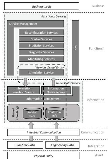
Figure 2.
Generic Digital Twin Architecture (GDTA) model.
The GDTA is based on the introduced 5D-DT concept and inspired by the 5C architecture for CPSs, because both concepts have a sufficient level of abstraction, which means they provide a more conceptual view than a concrete architecture. However, they are still useful to identify key components and functionality for DT.
The proposed GDTA defines the basic structure and components of a DT without specifying or binding it to certain technologies. For realizing a DT based on the GDTA, various existing technologies and frameworks can be used to implement its functionality on different layers. The specified components of the DT are explained in more detail regarding their associated RAMI 4.0 layer in the following paragraph.
Asset Layer—The physical representation of the DT is located at the Asset Layer and corresponds to the Physical Entity of the 5D-DT concept. It holds the physical parts of the CPS.
Integration Layer—At the integration layer, Run-time Data as well as Engineering Data can be distinguished. Run-time Data are generated by sensors or events and represent the current state of the physical entity. They are usually time-series data. These data are very dynamic, so the underlying infrastructure has to follow application-specific requirements, like big data processing or real-time reaction. Archives, e.g., special time-series databases, can be used to store these data for diagnosis and model identification purposes. Engineering Data are usually static data, which means they will not often change over time. Examples are the plant topology or information about a physical component inside a plant. This information is mostly available in analog formats, like drawings of pipe and instrumentation diagrams, and has to be digitized. Even if the information is already available in machine-readable form, the information has to be transformed and integrated into the DT as contextual information.
Communication Layer—Industrial communication or Industrial Internet of Things (IIoT) protocols can be applied within the Communication Layer of the DT. The concrete protocol depends on the requirements of the application, e.g., real-time capabilities or publication/subscription support. Thus, a combination of various protocols can be expected, which are made transparent to the upper layers by the Smart Data Service. Here, OPC Unified Architecture (OPC UA) is a representative in the context of Industry 4.0. Next to its communication capabilities, information modeling also enables the representation and access to context information through OPC UA.
Information Layer—Within the Information Layer of the DT architecture, data is gathered and enriched with semantics and related with other context information. Thus, the data dimension of the 5D-DT becomes an information dimension at this stage. The central component inside the Information Layer is a Shared Knowledge base, which stores contextual information about resources and services. Data are linked with this information to add semantics to it. Different levels of semantic expressivity can be achieved by applying different information modeling technologies. Ideally, data are stored in their original formats in proper databases. The Shared Knowledge base acts as a semantic integration layer for run-time data and engineering data by providing access to historical data (archives) and holding contextual information inside the Shared Knowledge. Access to the information inside the Shared Knowledge is granted by an Information Query Service. This service can retrieve information from the knowledge base and provide it to other services. The Information Insertion Service is used to add or change information from the upper layers of the DT architecture inside the Shared Knowledge base. Thus, information ownership and access have to be managed including data access mechanisms. This is performed by an Information Management component inside the DT architecture, which handles the information access of the Query and Insertion Service.
The above-mentioned components and services form the so-called Smart Data Service [23], which builds a central point of information inside the architecture. It provides information about resources and services through the Shared Knowledge base and makes it accessible for other services in the Functional Layer.
Functional Layer—In the Functional Layer, the service dimension of the 5D-DT concept is realized. A service-oriented architecture is applied to enable loose coupling and cohesion of certain functionality [24]. The services of the DT can be grouped by their functionality and can build on each other. Five groups are identified: Simulation Services, Monitoring Services, Diagnosis Services, Prediction Services, Control Services, and Reconfiguration Services. Next to these functional services, a Service Management component takes care of service registration, discovery, and obtaining status information about certain services. This information about a service is part of the Shared Knowledge in the Information Layer and will be inserted and queried through the offered Smart Data Service interface. The resource management is not handled by a central component, as the services have to handle their resources by themselves, facilitating the Shared Knowledge base.
Simulation Services are the core services, as they are part of the Virtual Entity of the 5D-DT concept. Typically, there exists not only one model of the physical entity in a DT, but a set of executable models that are specific for the intended purpose and also evolve over time [25]. Thus, different models for various domains, like the mechanical structure, thermal behavior, etc. can be hosted and used inside the Simulation Service of a DT. As for the other services, resources have to be managed by the service itself, and the related information about the models has to be made available through the Shared Knowledge base. A simulation model hosted by the Simulation Service in combination with related context information from the Shared Knowledge base generates a certain View of the Virtual Entity inside the DT.
Monitoring Services are elementary services to acquire data from the physical entity and observe its current state. An example could be a fault detection service, which can be implemented based on simple statistical models and indicate abnormal operating conditions of a plant.
Diagnostic Services are services supporting, for instance, condition monitoring or root cause analysis of faults. They can build upon underlying Monitoring Services in combination with Simulation Services to gain more insight into the current state of the Physical Entity.
Prediction Services are important for the DT to make decisions based on information about future events. Such services can be used, for instance, for predictive maintenance or the prediction of energy consumption. Also, external variables, like renewable energy production or prices at the energy market, can be predicted. Additionally, external prediction services can be integrated. The prediction results can be used by Control Services for realizing an optimized control or used to generate recommendations for the operating staff.
Control Services have an influence on the operation of the plant via recommendations over Human-Machine Interface (HMI) or direct access to the process control. Control Services with direct access can bypass the Smart Data Service in the Information Layer to change the state of the physical entity without additional delay. Usually, Control Services make use of monitoring, diagnosis, and prediction services to achieve optimized operation. Thereby, the control strategy can change over time, caused by a reconfiguration of the Physical Entity or new objectives specified by the business logic.
Reconfiguration Service. Reconfiguration means a rather static change of the fundamental properties of the Physical Entity by the DT itself. This has a significant influence on the context information inside the Shared Knowledge. Reconfiguration can be initialized through events or changed objectives inside the business logic, which resides inside the business layer. The Reconfiguration Service takes care of such changes inside the DT.
Humans have to be informed about the current state of the Physical Entity as well as the DT itself to interact with it. Thus, an appropriate HMI is very important for almost every service of a DT.
Business Layer—In this layer, the business logic resides, which can also orchestrate a large amount of DT. It defines the overall objectives (e.g., to reduce the risk of downtime or cost), which should be reached with the help of the DT. As this highly depends on the business strategy, it is not relevant for the design of the GDTA but only relevant via specific inputs.
4. Proof-of-Concept: Digital Twin Instantiation
The following section describes a prototypical implementation of the proposed GDTA as it is shown in Figure 2. The focus of the implementation is the Virtual Entity consisting of a Simulation Service in combination with context information, as it is a fundamental service inside the DT. The code of the prototype is publicly available in a GitLab repository (https://gitlab.tuwien.ac.at/iet/public/GDTA_Prototype).
To realize the Shared Knowledge base, Semantic Web technology is used, based on Resource Description Framework (RDF) and Web Ontology Language (OWL) to describe the resources and services. Already existing ontologies, like Ontology Web Language for Service (OWL-S), ML-Schema [26] and OWL-Time [27] are reused and extended with new concepts. The ontologies are created using the tool Protégé [28]. The ontologies are loaded into Apache Jena Fuseki Server v.3.16.0 running in a Docker container. Jena Fuseki provides a SPARQL Protocol and RDF Query Language (SPARQL) endpoint to access the information of the Shared Knowledge base. The service invocation is performed via Hypertext Transfer Protocol (HTTP) in combination with a Representational State Transfer (REST) API as suggested in [29].
4.1. Knowledge Representation Inside the Shared Knowledge Base
Semantic Web technologies are used to build the Shared Knowledge base as a central part of our Smart Data Service. Ontologies are used to hold information about resources and services in a formal and machine-readable way. A hierarchical design approach is used, consisting of a top-level-ontology and a domain ontology, as shown in Figure 3. Further hierarchy levels would be possible. The top-level ontology defines general terms that are common across all sub ontologies. Terms in the domain ontology are ranked under the terms of the top-level ontology. For the presented implementation the Base Service Ontology is defined as a top-level ontology holding general information about the available services of the DT. Other services implement their information inside the domain ontologies. For the current prototype, only the Simulations Service Ontology is implemented, but other domain ontologies can be developed quite similar.
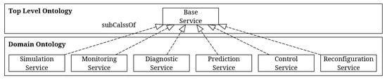
Figure 3.
Top Level and Domain Ontology structure.
4.1.1. Base Service Ontology
The Base Service Ontology holds the necessary information for a general service description, which helps to discover and access the service. The implementation of the Base Service Ontology consists of a service description based on OWL-S profile classes and properties, additionally defined Quality of Service (QoS) metrics for the services, and a specification of a service endpoint. OWL-S provides a set of vocabulary and semantic rules for formal description of Web Services. The information about a service is described using the OWL-S Profile, a subclass of ServiceProfile. More Information about OWL-S can be found in [26]. The main concepts and relations of the ontology are depicted in Figure 4. The grey concepts are part of OWL-S, whereas the white concepts are extensions and explained in more detail.
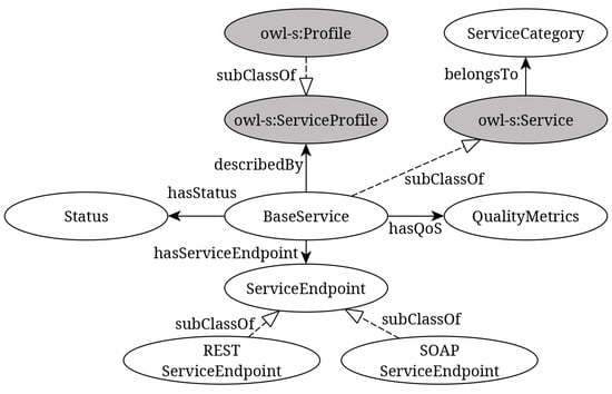
Figure 4.
Part of the Base Service Ontology concepts and their relations.
BaseService—The service is a subclass of the owl-s:Service class and described by the owl-s:Profile. The BaseService concept aggregates the essential information about the service, like the service endpoint, the current status, and quality metrics. A service is always related to a PhysicalEntity inside the ontology (not depicted in Figure 4). Thus, the services of a component or a whole asset can be retrieved from the Shared Knowledge base for the purpose of service discovery.
ServiceCategory—In order to classify a BaseService and define it as a certain functional service, the abstract class ServiceCategory is used. The categories correspond to the functional service types defined in the GDTA and also used for the grouping of the domain ontologies in Figure 3.
Quality Metrics—OWL-S has no capabilities for describing QoS for a certain service. To counteract, eleven additional properties are added to describe certain QoS metrics for a service, like Accessibility, ResponseTime, Availability, etc. This information can be used during service discovery to choose the best service if more than one is available.
Status—To gain information about the current service status, the last time of invocation, the invoked method, that invoked the service, and a service status message (“OK”, “In Use”,“Warning”,“Error”) is related with the service entity.
ServiceEndpoint—Each service has at least one service endpoint which enables service invocation or subscription in order to exchange data with a service. The endpoint categories can be flexible in nature and comprise of different protocols. In the prototypical implementation, a REST endpoint is specified in the ontology. However, endpoints are not restricted to that type, e.g., SOAP could also be used.
4.1.2. Simulation Service—Domain Ontology
A View on the Virtual Entity of the DT consists of a Simulation Service in combination with context information, stored in the Shared Knowledge base. The information about the simulation models used by the Simulation Services is captured by the Simulation Service—Domain Ontology. This ontology can be seen as a reference implementation for other domain ontologies. The main concepts of this ontology and their relations are shown in Figure 5.
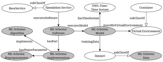
Figure 5.
Main Simulation Service—Domain Ontology concepts and their relations.
The domain service ontology inherits all classes and properties from the Base Service Ontology and adds domain-specific knowledge. For the implementation of the Simulation Service—Domain Ontology, ML-Schema is used to describe data-driven and physical simulation models within a Simulation Service. ML-Schema is developed to represent and interchange information on machine learning algorithms, datasets, and experiments [30]. The concepts in the ontology which are reused from ML-Schema are depicted with grey background in Figure 5. More Information about ML-Schema can be found in [31]. The additional concepts of the domain ontology are depicted with a white background.
The SimulationService is a special type of service for describing simulation models inside the DT. It inherits all properties from the BaseService concept in the top-level ontology. The Simulation Service executes a certain ML-Schema:Software which consists of an ML-Schema:Implementation and ML-Schema:Model. The model is trained on a certain Dataset, which has properties to describe how the data can be used (dataset location, dataset format, feature names, etc.).
The Virtual Environment provides a description of the environment in which a model is executed. A Container is one possibility of such a concrete realization of a Virtual Environment. The presented implementation uses a Docker container for providing such an environment. Each ML-Schema:Model is related with a OWL-Time:TimeInstant to capture the date and time of its training or parameter identification. This information is used to handle various versions of a model.
4.2. Simulation Service API
The Simulation Service is realized as a microservice that communicates over REST-ful service endpoints with other services or agents. The stored information inside the Shared Knowledge base is made available by calling HTTP methods on the endpoints. In the same way, information can be inserted into the knowledge base, and the Simulation Service can be invoked. Currently, information about the simulation model and the service status can be retrieved, models and data can be uploaded, and the model can be trained. Also, predictions can be made by the Simulation Service, calling an HTTP method on a special endpoint. A full list of the implemented service endpoints, as well as the required parameters, can be found in Table 2. The Simulation Service adds information about a new model instance to the Shared Knowledge base automatically, whenever a new model is created or successfully trained, or a new hyper-parameter for the model is set. In the current implementation, only Matlab simulation models are supported by the Simulation Service.
Table 2.
Hypertext Transfer Protocol (HTTP) endpoint description for the implemented Simulation Service Application Programming Interface (API).
4.3. Use Case: Packed-Bed Thermal Energy Storage
The PBTES is a reliable high-temperature thermal energy storage device with low investment costs. It is capable of operating at temperatures of above 800 C [32] and thus applicable in variable industrial energy systems, as, for example, in the steel, glass, and cement industry or in solar power plants. Thermal energy storage solutions are required to match heat supply with demand and, thus, can contribute significantly to meeting society’s desire for more efficient, environmentally friendly energy use [33]. Increasingly complex energy systems, induced by the transition to renewable energy sources [34], feature high flexibility that requires adequate control and optimization concepts. For fast analysis of various operating conditions and different parameters by simulation, detailed, but efficient models of such systems are needed. A PBTES is therefore considered as an ideal use case for a DT implementation.
4.3.1. Packed-Bed Thermal Energy Storage Test Rig
The PBTES represents the Physical Entity for the instantiated DT in this use case. It is located at the laboratory of the Institute for Energy Systems and Thermodynamics (IET) at TU Wien. A schematic illustration of the PBTES for loading and unloading is shown in Figure 6. It consists of an insulated vessel filled with gravel, an electric heater, and a ventilation unit. For charging the PBTES, hot air is ventilated through the gravel, which increases its temperature and stores sensible thermal energy. For discharging, cold air is ventilated through the hot tank and the heated air leaves the storage. To assess the thermodynamic conditions in the test rig’s storage vessel, it is equipped with a total of 18 calibrated thermocouples, as well as mass flow and pressure measurement sensors at the inlet and outlet. For a detailed description of the test rig and it’s measurement instrumentation, please refer to [35,36].
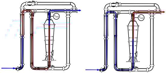
Figure 6.
Bulk container of the Packed Bed Thermal Energy Storage (PBTES) installed at the laboratory in load and unload state.
Various models were developed to simulate the thermodynamic behavior of the PBTES, i.e., the measured values for intrinsic and outlet temperatures given the input values for temperature and mass flow. A physical model based on a 1D finite-difference approach was presented in [37]. A grey box model using recurrent neural networks was published in [38]. Furthermore, physical and data-driven modeling approaches for PBTES were compared and evaluated regarding prediction accuracy and modeling, as well as the computational effort [35]. In general, each of these evaluated simulation models can be reused in the Simulation Service of the DT. For the presented use case the mentioned grey box model was chosen, which was developed in [38].
4.3.2. Simulation Service Invocation
To provide some insights into the capability of our prototypical DT implementation, we show the procedure of loading a dynamic thermal model of the PBTES into the DT, train the model with available data, and use the model for a time-series prediction of the outlet temperature of the PBTES. The previously explained Simulation Service API is used to perform these tasks. The Simulation Service interacts with the Shared Knowledge base in the background to store and retrieve context information. This information is organized using the explained Base Service Ontology and the Simulation Service—Domain Ontology.
Uploading a Simulation Model—The implemented Simulation Service allows for uploading new simulation models. As mentioned before, a “Neural Net” grey box model, which is implemented in Matlab is used. More details about the simulation model can be found in [38]. Figure 7 shows the sequence diagram of the upload process. For uploading a new model, the HTTP POST method is invoked on the endpoint with the URL /upload/model. As a parameter, the Matlab file is included in the HTTP body. The endpoint returns the internal path where the simulation model is stored. This path is needed afterward to access the specific model for training or prediction.
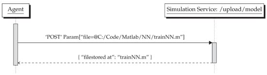
Figure 7.
Sequence diagram for uploading a dataset at the service endpoint.
Uploading a Dataset—The HTTP POST method is used to upload a new dataset by invoking the simulation service’s upload/data endpoint. The internal file path is returned in the HTTP response. The returned path is used in order to train a model or to make predictions with the uploaded dataset. The procedure is shown in the sequence diagram in Figure 8.
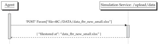
Figure 8.
Sequence diagram for uploading a model at the service endpoint.
Train a Simulation Model—In order to train an uploaded simulation model with an uploaded dataset, the HTTP PUT method is invoked at the Simulation Service endpoint with the URL /train. The HTTP request holds the path to the uploaded training data and the model path as arguments. Additionally, simulation model parameters can also be forwarded as a dictionary. As a result of the training process, a new model description is returned in the JSON format and the information is also stored in the Shared Knowledge base. The old model is archived but can be used for predictions afterwards as well. The sequence is depicted in Figure 9, where just a small fraction of the returned information, formatted in JSON, is shown.
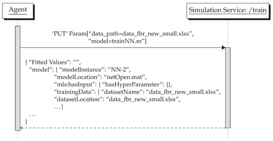
Figure 9.
Sequence diagram for training a simulation model at the service endpoint.
Make a Prediction—In order to use the Simulation Service for predictions, the endpoint with the URL /predict has to be called using the HTTP GET method. Its arguments are the path to an input dataset and optionally a path to a model. If no path to a model is specified the service uses per default the most recently trained model to make predictions. The service endpoint returns the predictions in a JSON array as shown in Figure 10.
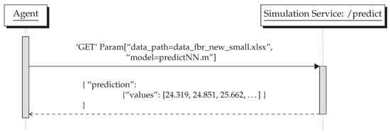
Figure 10.
Sequence diagram for using a model to predict a time series at simulation endpoint.
In the presented use case of the PBTES, the output temperature is predicted by the Simulation Service for a specified input trajectory. The predicted loading cycle of the PBTES over time is shown in Figure 11. These prediction results could further be used for an optimized control strategy performed by the DT.
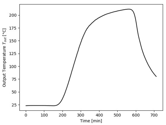
Figure 11.
Results of the Simulation Service for the output temperature of the Packed-Bed Thermal Energy Storage (PBTES) for a specific load cycle.
5. Discussion
The aim of our proposed GDTA is a simple architectural model that captures the essential components of a DT in a technology-independent way. We presented various concepts and architectures for DTs in Section 1.2. It becomes clear that DTs have to be able to handle various types of models for different applications. Also, a structuring of different functionality by using services as well as information and knowledge management are essential to gain a certain level of cognition.
The user interaction with a DT is a very important aspect, as in Industry 4.0 the workers or operators will be the most flexible part of the CPS. They have the role of a strategical decisions-maker and problem solver [39] so they have to interact closely with a DT. This is not reflected by most frameworks or concepts.
Almost all presented frameworks or architectures use a layered structure to specify some functionality. Various layers are introduced with different names, which often perform similar tasks. This leads to confusion. The alignment of our architecture with RAMI 4.0 facilitates a standardized wording and common understanding of the layers in a DT. This helps to classify, combine, and re-use already existing frameworks and technologies in the area of Industry 4.0 and the IIoT for designing and implementing a DT.
In the following paragraph, the concepts, architectures, and frameworks for DTs, which have been introduced in Section 1.2 are re-visited and set into relation with our proposed GDTA.
The foundation of our GDTA is the 5D-DT concept [13]. The data and service dimension of this concept is refined in our architecture by identifying service clusters and introducing a Shared Knowledge base, which semantically enriches available data and stores information about resources and services. This Shared Knowledge base is the main component inside the Smart Data Service in our proposed architecture and enhances the data dimension of the 5D-DT.
The suggested architecture for an “Intelligent Digital Twin” in [14] emphasizes the usage of AI inside a DT to evaluate “what-if” scenarios. Therefore, certain components in the architecture are defined, like an “Intelligent Algorithm” module, or a “Co-simulation Interface”. In our opinion, these are quite specific modules, which can be implemented by distinct services of the proposed GDTA (e.g., a simulation service can support co-simulation), but do not always have to be present in a DT. Also, the separation of “intelligent” algorithms from the services into dedicated components seems not always beneficial. Nevertheless, important aspects and problems are addressed in this work, like user feedback, which is also considered in our architecture.
A reference framework for DTs within CPSs is presented in [6] where four main building blocks are identified. These blocks can be mapped to certain layers of our proposed architecture, which is aligned with RAMI 4.0: The key concepts of the “Service Platform” are found in the Functional Layer in our architecture. The “Physical Entity Platform” is equivalent to the Asset and Integration Layer. In addition, our architecture captures the aspect of the communication layer. The main aspects of the “Data Management Platform” can be located on the Information Layer. As we propose a service-oriented architecture for the GDTA, some of the mentioned data management methods, like data processing, data cleaning, data analysis, data mining and information extraction can be carried out by specific services of the Functional Layer. The “Virtual Entity Platform” includes various “Semantic Models”. This corresponds to our idea of a View on the Virtual Entity in the GDTA, consisting of various semantic simulation models in combination with context information, stored in the Shared Knowledge base. The proposed reference framework and the identified structural properties of the DT are very generic, but some additional aspects can be found in our GDTA. So we introduced a Service Management component and defined groups of common service types inside a DT, which help to structure and implement certain services. We also see the HMI interaction as an important part of our GDTA which almost every service has to implement. Thus, we include a HMI component in our GDTA.
The conceptual architecture of the Cognitive Twin Toolbox presented in [15] also introduces a “Knowledge Repository” in combination with “Cognitive Services”. This is only applied for a “cognitive Twin”. The basic DT concept implements only a so-called “Metadata Repository”. A separation into two distinguishable components, as presented in [15] seems neither beneficial nor has practical advantages. Therefore, we introduced the Shared Knowledge base, which acts as a central point of information in our GDTA. Also a “Model Management Layer” is not explicitly stated in our architecture as resource management has to be done by the service implementations themselves. The information about the resources has to be made available through the Shared Knowledge base. The functions described for the “Twin Management Layer” can be located in a Reconfiguration Service in the GDTA. The COGNITIVE Twin toolbox is a solution with various components that seems to be specific for their definition of the so-called “Hybrid” or “Cognitive Twin”. Thus, we tried to reduce the components of the proposed GDTA to be as simple and generic as possible.
The conceptual model of a DT in the context of IoT, as presented in [16] introduces five layers which are quite similar to the layers of RAMI 4.0. The “Physical Space” corresponds to the Asset and Integration Layer; the “Virtual Layer”, to the Information Layer; the “Data Analytics and Visualization” and “Application”, to the Functional Layer. In our architecture, we chose a more service-oriented view of the various applications of the DT. Providing semantics of the data and a shared knowledge base is not explicitly handled in this conceptual model, in contrast to the suggested GDTA. The conceptual DT model emphasizes the importance of security by defining a vertical module overall specified layers. In our generic architecture, such a module is not explicitly depicted, as it applies to all levels of RAMI 4.0 implicitly and must be considered for the asset as a whole [40].
The AAS is a promising way of standardization as shown in [17] but still ongoing work. In its current state, the concept of the AAS meta-model can be applied and implemented in line with our proposed architecture. It was already shown, that the defined data model of the AAS can be semantically lifted to a knowledge representation based on RDF [41]. In the context of our proposed architecture, this enables the representation of the AAS inside the Shared Knowledge base.
The presented proof-of-concept implementation is the basis for further development of other services inside the DT. Additionally, the knowledge representation of the simulation models can be extended with application-specific domain ontologies. This would facilitate the integration of other semantic models of the DT as described in [6]. The hierarchical and modular ontology design, using a top-level ontology as well as various domain ontologies, facilitates the integration of new concepts and ontologies. These hierarchies can be further increased by introducing additional levels, like application or even task ontologies. The alignment with already existing or emerging standards, represented in OWL, can be performed by having similar concepts in the upper layers of the ontology hierarchy and using the owl:equivalentClass property defined in OWL 2.
The presented use case was chosen in the domain of industrial energy system, but the proposed GDTA can also be applied for a broader spectrum of applications. For this reason, we will investigate other domains and apply the proposed GDTA also for other use cases.
6. Conclusions
A novel GDTA based on the 5D-DT concept is presented and evaluated based on a prototypical proof-of-concept implementation. Other concepts, architectures, or frameworks in literature often use a layered structure with similar functionality but different names. To overcome this problem, we aligned our GDTA with the IT dimension of RAMI 4.0. This helps to have a common naming and understanding of the layers inside the GDTA, which facilitates the development of a DT.
The presented GDTA is technology-independent. We instantiated it based on Semantic Web technology and showed the suitability for handling context information about resources and services in combination with simulation models. This enables application dependable Views on the Virtual Entity of the DT. In our proof-of-concept, ontologies build the foundation for the Shared Knowledge base of the Smart Data Service. Existing ontologies like OWL-S or ML-Schema are reused to describe resources and services and facilitate interoperability.
Future work will further extend the service infrastructure inside the DT, including service management. Other functional services of a DT will be implemented and the domain-specific ontologies will be extended. For this goal, an advanced version management system has to be developed to keep track of changes made on the DT during its life-cycle.
Another research direction will investigate the applicability of already available IoT standards and frameworks at the Communication and Information Layer of our GDTA. It will investigate how those can be organized in the hierarchical dimension of the RAMI 4.0 using edge and cloud computing.
Author Contributions
Conceptualization, G.S., M.S. and L.K.; methodology, G.S.; software, M.S.; writing—original draft preparation, G.S., M.S. and L.K.; contribution to contents, review and editing, W.K and R.H.; supervision, W.K. and R.H. All authors have read and agreed to the published version of the manuscript.
Funding
This research received no external funding, but was supported by the doctoral school SIC!—Smart Industrial Concept! and the Open Access Funding of TU Wien.
Acknowledgments
The authors acknowledge TU Wien Bibliothek for financial support through its Open Access Funding Programme.
Conflicts of Interest
The authors declare no conflict of interest.
Abbreviations
The following abbreviations are used in this manuscript:
| 5D-DT | Five-Dimensional Digital Twin |
| AAS | Asset Administration Shell |
| PBTES | Packed-Bed Thermal Energy Storage |
| CPPS | Cyber–Physical Production System |
| CPS | Cyber–Physical System |
| DT | Digital Twin |
| GDTA | Generic Digital Twin Architecture |
| HMI | Human-Machine Interface |
| HTTP | Hypertext Transfer Protocol |
| IIoT | Industrial Internet of Things |
| IoT | Internet of Things |
| IT | Information Technology |
| OPC UA | OPC Unified Architecture |
| OWL | Web Ontology Language |
| OWL-S | Ontology Web Language for Service |
| QoS | Quality of Service |
| RAMI 4.0 | Reference Architecture Model Industry 4.0 |
| RDF | Resource Description Framework |
| REST | Representational State Transfer |
| SPARQL | SPARQL Protocol and RDF Query Language |
References
- Parida, V.; Sjödin, D.; Reim, W. Reviewing literature on digitalization, business model innovation, and sustainable industry: Past achievements and future promises. Sustainability 2019, 11, 391. [Google Scholar] [CrossRef]
- Roblek, V.; Meško, M.; Krapež, A. A Complex View of Industry 4.0. SAGE Open 2016, 6. [Google Scholar] [CrossRef]
- Tao, F.; Zhang, H.; Liu, A.; Nee, A.Y. Digital Twin in Industry: State-of-the-Art. IEEE Trans. Ind. Inform. 2019, 15, 2405–2415. [Google Scholar] [CrossRef]
- UNIDO. Accelerating Clean Energy through Industry 4.0: Manufacturing the Next Revolution; Technical Report; United Nations Industrial Development Organization: Vienna, Austria, 2017. [Google Scholar]
- Lu, Y.; Liu, C.; Wang, K.I.; Huang, H.; Xu, X. Digital Twin-driven smart manufacturing: Connotation, reference model, applications and research issues. Robot. Comput. Integr. Manuf. 2020, 61, 101837. [Google Scholar] [CrossRef]
- Josifovska, K.; Yigitbas, E.; Engels, G. Reference Framework for Digital Twins within Cyber–Physical Systems. In Proceedings of the 2019 IEEE/ACM 5th International Workshop on Software Engineering for Smart Cyber–Physical Systems, SEsCPS 2019, Montreal, QC, Canada, 28 May 2019; pp. 25–31. [Google Scholar] [CrossRef]
- Malakuti, S.; van Schalkwyk, P.; Boss, B.; Ram Sastry, C.; Runkana, V.; Lin, S.W.; Rix, S.; Green, G.; Baechle, K.; Varan Nath, C. Digital Twins for Industrial Applications. Definition, Business Values, Design Aspects, Standards and Use Cases. Version 1.0. White Paper 2020, 1–19. [Google Scholar]
- Grieves, M. Digital Twin: Manufacturing Excellence through Virtual Factory Replication. A Whitepaper by Dr. Michael Grieves. White Paper 2014, 1–7. [Google Scholar]
- Monostori, L. Cyber–physical production systems: Roots, expectations and R&D challenges. Procedia CIRP 2014, 17, 9–13. [Google Scholar] [CrossRef]
- Uhlemann, T.H.; Lehmann, C.; Steinhilper, R. The Digital Twin: Realizing the Cyber–Physical Production System for Industry 4.0. Procedia CIRP 2017, 61, 335–340. [Google Scholar] [CrossRef]
- Lee, J.; Bagheri, B.; Kao, H.A. A Cyber–Physical Systems architecture for Industry 4.0-based manufacturing systems. Manuf. Lett. 2015, 3, 18–23. [Google Scholar] [CrossRef]
- Jones, D.; Snider, C.; Nassehi, A.; Yon, J.; Hicks, B. Characterising the Digital Twin: A systematic literature review. CIRP J. Manuf. Sci. Technol. 2020, 29, 36–52. [Google Scholar] [CrossRef]
- Tao, F.; Zhang, M.; Nee, A. Five-Dimension Digital Twin Modeling and Its Key Technologies. Digit. Twin Driven Smart Manuf. 2019, 63–81. [Google Scholar] [CrossRef]
- Ashtari Talkhestani, B.; Jung, T.; Lindemann, B.; Sahlab, N.; Jazdi, N.; Schloegl, W.; Weyrich, M. An architecture of an Intelligent Digital Twin in a Cyber–Physical Production System. At-Automatisierungstechnik 2019, 67, 762–782. [Google Scholar] [CrossRef]
- Abburu, S.; Berre, A.J.; Jacoby, M.; Roman, D.; Stojanovic, L.; Stojanovic, N. COGNITWIN—Hybrid and Cognitive Digital Twins for the Process Industry. In Proceedings of the 2020 IEEE International Conference on Engineering, Technology and Innovation (ICE/ITMC), Cardiff, UK, 15–17 June 2020; pp. 1–8. [Google Scholar] [CrossRef]
- Digital Twin Conceptual Model within the Context of Internet of Things. Future Internet 2020, 12, 163. [CrossRef]
- Bader, S.; Barnstedt, E.; Bedenbender, H.; Billman, M.; Boss, B.; Braunmandl, A.; Clauer, E.; Deppe, T.; Diedrich, C.; Flubacher, B.; et al. Details of the Asset Administration Shell. Plattf. Ind. 4.0 2019, 1, 473. [Google Scholar]
- Adolphs, P.; Bedenbender, H.; Dirzus, D.; Martin, E. Reference Architecture Model Industrie 4.0 (RAMI4.0); Technical Report July; VDI/VDE-Gesellschaft: Düsseldorf, Germany, 2015. [Google Scholar]
- IEC. IEC 62264 Enterprise-Control System Integration; Technical Report; International Electrotechnical Commission: Geneva, Switzerland, 2016. [Google Scholar]
- Fernández-López, M.; Gómez-Pérez, A.; Juristo, N. METHONTOLOGY: From Ontological Art Towards Ontological Engineering. Spring Symp. Ontol. Eng. AAAI 1997, SS-97-06, 33–40. [Google Scholar] [CrossRef]
- Poveda-Villalón, M.; Gómez-Pérez, A.; Suárez-Figueroa, M.C. OOPS! (OntOlogy Pitfall Scanner!): An On-line Tool for Ontology Evaluation. Int. J. Semant. Web Inf. Syst. (IJSWIS) 2014, 10, 7–34. [Google Scholar] [CrossRef]
- Glimm, B.; Horrocks, I.; Motik, B.; Stoilos, G. HermiT: Reasoning with Large Ontologies; Computer Science; University of Oxford: Oxford, UK, 2009; p. 64. [Google Scholar]
- Koschnick, G. Industrie 4.0: Smart Services; Technical Report July; German Electrical and Electronic Manufacturers’ Association: Frankfurt am Main, Germany, 2016. [Google Scholar]
- Jammes, F.; Smit, H. Service-oriented paradigms in industrial automation. IEEE Trans. Ind. Inform. 2005, 1, 62–70. [Google Scholar] [CrossRef]
- Boschert, S.; Rosen, R. Digital Twin—The Simulation Aspect. In Mechatronic Futures; Hehenberger, P., Bradley, D., Eds.; Springer International Publishing: Cham, Switzerland, 2016; pp. 59–74. [Google Scholar] [CrossRef]
- Martin, D.; Burstein, M.; Hobbs, J.; Lassila, O.; McDermott, D.; McIlraith, S.; Narayanan, S.; Paolucci, M.; Parsia, B.; Payne, T.; et al. OWL-S: Semantic markup for web services. W3C Memb. Submiss. 2004, 22. [Google Scholar]
- Hobbs, J.R.; Little, C. Time Ontology in OWL. W3C Candidate Recommendation; Technical Report; World Wide Web Consortium (W3C): Cambridge, MA, USA, 2020. [Google Scholar]
- Knublauch, H.; Fergerson, R.W.; Noy, N.F.; Musen, M.A. The Protégé OWL plugin: An open development environment for semantic web applications. In International Semantic Web Conference; Springer: Berlin/Heidelberg, Germany, 2004; pp. 229–243. [Google Scholar]
- Jacoby, M.; Usländer, T. Digital Twin and Internet of Things—Current Standards Landscape. Appl. Sci. 2020, 10, 6519. [Google Scholar] [CrossRef]
- Publio, G.C.; Esteves, D.; Lawrynowicz, A.; Panov, P.; Soldatova, L.N.; Soru, T.; Vanschoren, J.; Zafar, H. ML-Schema: Exposing the Semantics of Machine Learning with Schemas and Ontologies. arXiv 2018, arXiv:1807.05351. [Google Scholar]
- Ławrynowicz, A.; Panov, P.; Soldatova, L.; Soru, T.; Vanschoren, J. ML Schema Core Specification. W3C Release 17 October 2016; Technical Report; World Wide Web Consortium (W3C): Cambridge, MA, USA, 2016. [Google Scholar]
- Andreozzi, A.; Bianco, N.; Manca, O.; Nardini, S.; Naso, V. Numerical investigation of sensible thermal energy storage in high temperature solar systems. Comput. Methods Exp. Meas. XIV 2009, 48, 461–472. [Google Scholar] [CrossRef]
- Dincer, I.; Rosen, M.A. Chapter 6—Heat Storage Systems. In Exergy Analysis of Heating, Refrigerating and Air Conditioning; Dincer, I., Rosen, M.A., Eds.; Elsevier: Boston, MA, USA, 2015; pp. 221–278. [Google Scholar] [CrossRef]
- Lund, H.; Østergaard, P.; Connolly, D.; Ridjan, I.; Mathiesen, B.; Hvelplund, F.; Thellufsen, J.; Sorknses, P. Energy storage and smart energy systems. Int. J. Sustain. Energy Plan. Manag. 2016, 11, 3–14. [Google Scholar] [CrossRef]
- Hofmann, R.; Halmschlager, V.; Koller, M.; Scharinger-Urschitz, G.; Birkelbach, F.; Walter, H. Comparison of a physical and a data-driven model of a Packed Bed Regenerator for industrial applications. J. Energy Storage 2019, 23, 558–578. [Google Scholar] [CrossRef]
- Michalka, A. Experimentelle Untersuchungen eines Festbettregenerators mit feinem Kies als Speichermaterial. Ph.D. Thesis, Technicacl University of Vienna, Vienna, Austria, 2018. [Google Scholar]
- Mayrhuber, F.; Walter, H.; Hameter, M. Experimental and numerical investigation on a fixed bed regenerator. In Proceedings of the 10th International Conference on Sustainable Energy and Environmental Protection, Bled, Slovenia, 27–30 June 2017; University of Maribor Press: Maribor, Slovenia, 2017; p. 30. [Google Scholar]
- Halmschlager, V.; Koller, M.; Birkelbach, F.; Hofmann, R. Grey Box Modeling of a Packed-Bed Regenerator Using Recurrent Neural Networks. IFAC-PapersOnLine 2019, 52, 765–770. [Google Scholar] [CrossRef]
- Gorecky, D.; Schmitt, M.; Loskyll, M.; Zühlke, D. Human-machine-interaction in the industry 4.0 era. In Proceedings of the 2014 12th IEEE International Conference on Industrial Informatics, INDIN 2014, Porto Alegre, Brazil, 27–30 July 2014; pp. 289–294. [Google Scholar] [CrossRef]
- Jochem, R.; Klasen, W.; Linke, L.; Jaenicke, L.; Gamer, T.; Stolz, M.; Mehrfeld, J.; Teuscher, A.; Fritsche, W. Security in RAMI4.0; Technical Report; Platform Industrie 4.0: Berlin, Germany, 2016. [Google Scholar]
- Bader, S.R.; Maleshkova, M. The Semantic Asset Administration Shell; Springer International Publishing: Berlin/Heidelberg, Germany, 2019; Volume 1, pp. 159–174. [Google Scholar] [CrossRef]
Publisher’s Note: MDPI stays neutral with regard to jurisdictional claims in published maps and institutional affiliations. |
© 2020 by the authors. Licensee MDPI, Basel, Switzerland. This article is an open access article distributed under the terms and conditions of the Creative Commons Attribution (CC BY) license (http://creativecommons.org/licenses/by/4.0/).