1. Introduction
Building Information Modeling (BIM) is an influential methodology that has been applied with great success in the domain of Architecture, Engineering, and Construction (AEC) [
1,
2,
3]. BIM has many applications such as project sustainability [
4,
5,
6], occupational health and safety [
7,
8], project cost control [
9], coordination between project agents [
1,
10], and scheduling [
11].
Despite the fact that the literature offers many studies carried out with BIM from different approaches, there are few works that analyze the design of a BIM building together with the design of MEP (Mechanical, Electrical, and Hydrosanitary (Plumbing)) facilities, unifying both work environments and giving importance to IFC (Industry Foundation Classes) as a connecting link between information and communication within the project.
BIM is considered one of the most influential innovations in the construction industry and facilitates work in different areas such as construction, industry, manufacturing, and facilities management [
1,
12,
13,
14,
15].
The BIM concept was suggested by Eastman [
16] and later used by Van Nederveen and Tolman [
17] and Tolman [
18], and can be described as an integrative technology that modifies the digital process of representing buildings [
19]. BIM is a collaborative work methodology for the creation and management of a construction project [
20]. Over the last decades, there have been numerous contributions made around BIM and its features. BIM is defined as: “A set of interacting policies, processes and technologies generating a methodology to manage the essential building design and project data in digital format throughout the building’s life-cycle” [
21,
22]. Nevertheless we highlight the following definition of BIM: “An integrated and participatory process that improves the digital representation of projects and optimizes the analysis of construction (times, costs and procedures), to guarantee the success of the project execution” [
23].
Therefore, BIM can be defined as a work methodology that integrates and involves digital technologies based on two pillars: Communication and collaboration [
24]. Its objective is to centralize all project information in a digital information model created by all its agents [
25]. BIM represents the evolution of traditional design systems based on the plan, as it incorporates geometric (3D), time (4D), cost (5D), environmental (6D), and maintenance (7D) information [
25,
26].
The use of BIM goes beyond the design phases, covering the execution of the project and extending throughout the life cycle of the building, allowing its management and reducing operating costs [
25,
27]. Therefore, BIM is a technology that can improve the efficiency, connectivity, and performance of many processes within the construction industry [
28]. Several researchers have done reviews in related areas of current BIM research and its possible applications throughout the entire life cycle of the building [
29,
30,
31]. Overall, the application of BIM software for complex sport facilities design is interesting [
32]. There are authors who present work with BIM technology, but only from the point of its use for the maintenance of installations [
33]. The approximation of the planning functions to the real sequence of execution of the work, through the development and adoption of BIM tools, allows for a visualization of the execution of a digital model that was projected over time (4D planning), as well as the expected costs (5D planning) [
34].
To allow the sharing of all information, the OpenBIM methodology was created, which is based on the use of open standards. In BIM, the IFC (Industry Foundation Classes) serves as a data exchange format between agents, processes, and applications, which is defined by the ISO 16739: 2013 Standard [
35]. IFC is a particular data format that allows the exchange of an informational model without loss or distortion of data or information. It is an open, neutral format, which is not controlled by software producers, and was planned to facilitate interoperability between various operators. The IFC is designed to produce all the information about the building throughout its entire life cycle, from the preliminary design to its execution and maintenance, going through the different phases of design and planning. The main advantage offered by the IFC format is the possibility of collaboration between the various figures involved in the construction process, allowing the exchange of information through a standard format. This leads to higher quality, a reduction in errors, a reduction in costs, and saves time with data and information consistency throughout the execution and maintenance process.
MEP is the acronym for Mechanical, Electrical, and Hydrosanitary (Plumbing) facilities. In software it refers to the capacity of a program to support the designer, calculator, or draftsman in the development of construction services. These programs can work on a 2D or 3D CAD (Computer Aided Design) basis. However, generally, these solutions are integrated with other BIM-based applications to take advantage of the benefit of integration without loss of information because the Construction Model is unique, regardless of the vertical application used [
36]. Being a manual process, which involves errors, it is time consuming and expensive, so the most challenging task which requires iteration and experience, involving considerable time and human resources is MEP coordination [
8,
37,
38].
BIM has significant advantages over traditional CAD methodology, especially in large-scale works, to the point that the execution of many large projects carried out in recent years would not have been possible without applying BIM technology. Additional advantages of BIM over CAD are: BIM projects work with the properties of materials, cost, and planning studies can be carried out, as well as sustainability studies. BIM allows parameterization and any modification in the project is carried out in real time both in the drawings and in graphic documentation. BIM allows you to quantify, measure, and predict construction costs. In addition to the above, BIM allows the end customer to be involved in decision making within the virtual environment.
The main objective of the proposed case study is to present a workflow for the application of BIM software in the design of buildings and sports facilities and to analyze the interaction between BIM-MEP work environments. The flow of project information between both environments has a holistic view of the process, through the IFC format. This case study shows the application of BIM for modeling different types of buildings and the application of MEP for the design and calculation of facilities. This project is illustrative of how BIM has been used and worked in a MEP environment.
2. Aims and Procedures
The objective of this case study has been the design of a university sports pavilion in the area of Isla de la Cartuja in Seville (Spain). This case study is the result of an academic work that shows the learning application by doing methodology to explain the BIM-MEP procedure. Due to a lack of facilities of this type, it was decided to design sports facilities that can accommodate internal sports competitions, in addition to the possibility of hosting international university competitions in order to give greater visibility to the University of Seville within the international academic scene. This pavilion will also house a large gym inside, which can offer quality facilities close to the university. This project is illustrative of how BIM has been used and works in a MEP environment.
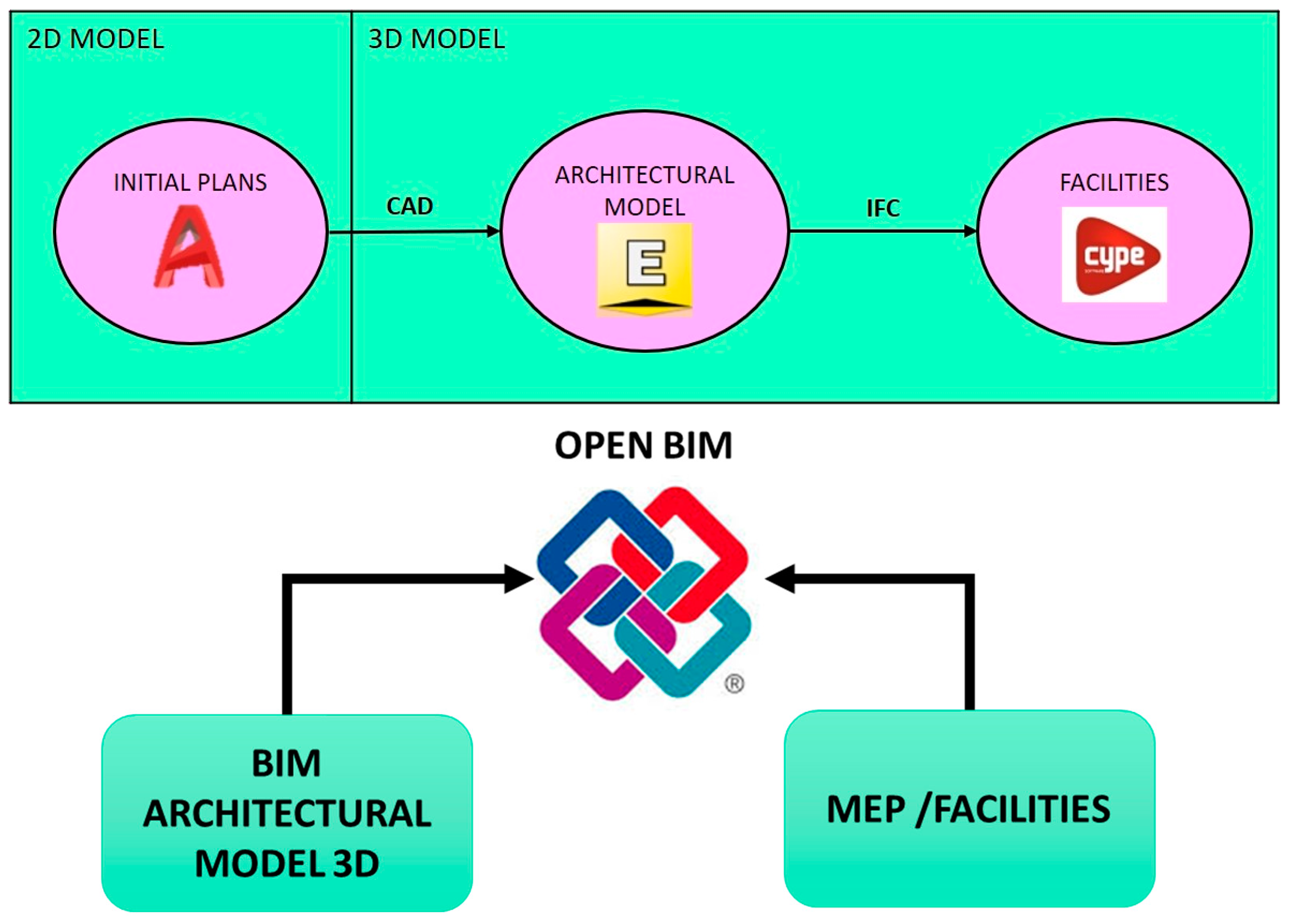
The methods used for the design of the pavilion was the use of AutoCAD
® (2020, Autodesk, San rafael, CA, USA) for the design of 2D plans, which served as the basis for carrying out the 3D modeling of the building using the BIM Edificius
® (BIM One, Acca Software, Bagnoli Irpino, Italy) software. Finally, the BIM model created was applied to calculate the building’s facilities using the CYPECAD MEP
® (2019 b, Cype Ingenieros, Alicante, España) software, using the IFC format, where information can be transferred from one software to the other, working with the specific regulations of the country for the design and calculation of the facilities (
Figure 1).
Nowadays, any BIM software allows the 3D design of the building to be carried out, without the need for CAD drawings. This requires a BIM modeler at an expert level and is capable of designing directly with three-dimensional software. It is clarified that the procedure that is shown from CAD to BIM is justified because there are still many projects where the 2D plans of the building are available. It is recommended that if the project is a new construction, we work only in the BIM environment and if the project is to model an existing building in 3D, then to start the BIM from the CAD drawings as long as they are available. Once the 3D model was made using BIM, the software is able to export the information to IFC format. The MEP tools are able of to recognize the 3D model from an IFC file: Definition of building elements, pre-manufactured products, mechanical/electrical systems, and even the most abstract models for structural and energy analysis, cost subdivision, job scheduling, and much more. Once the architectural model is recognized in a MEP environment, we are able to design and calculate the building’s facilities thanks to the interoperability and exchange of data in a safe way, without errors and/or loss of information. The term OpenBIM refers to “a collaborative approach to the design and construction of buildings based on open standards and workflows”. Undoubtedly, an essential requirement for OpenBIM is the use of open and neutral data formats. This is why the IFC format is the most chosen solution for OpenBIM.
3. Modeling
3.1. Situation and Location
The sports pavilion will be located on a plot in the north of Isla de la Cartuja in Seville (Spain). The surface of the plot is 13,166 m
2, of which the pavilion occupies a surface area of 3803 m
2. Altogether, the pavilion covers 7606 m
2 (
Figure 2).
3.2. CAD Templates
For the design of the pavilion it will be necessary to make an initial design of the floor plans using CAD tools such as AutoCAD
®, which we will introduce into Edificius
® and which will serve as templates to carry out the 3D survey of the building (
Figure 3). This procedure will facilitate the design work and even if they do not involve the final design of the project, they will serve as a basis on which to work and facilitate later changes.
Once the CAD files are introduced to the BIM environment, we manage the leveling layers and can begin the 3D modeling process. The BIM program allows us to select and apply different types of materials for each construction element, also allowing us to import objects with predefined properties, if it is previously designed, or to create it ourselves in a library. In addition to the morphological information of the construction elements designed in the BIM environment, we can obtain from the model tables information about the geometry, properties, materials, and quantities of various designed construction elements.
3.3. Structure
The pavilion will have a mixed concrete and metal structure, and will consist of a 60 cm wide and 30 cm high reinforced concrete slab. The main entrance will have a 30 cm reinforced concrete slab. The pillars will be 35 × 35 cm also of concrete, and metal trusses will be supported on them, on which the roof supporting straps will be mounted; this roof will be constructed using a sandwich panel (
Figure 4).
3.4. Exterior Facade and Illuminated Facade
The pavilion will have a ventilated facade with ceramic plates around its perimeter, as well as an air chamber and mineral wool insulation (
Figure 5 and
Figure 6).
An illuminated façade will be installed around the perimeter of the pavilion. This will be formed by metal frames (
Figure 7a) mounted on metal profiles acting as supports (
Figure 7b) and will be connected to pillars by means of anchor plates (
Figure 7c). On the metal panels, a fabric will be spread that will be illuminated from behind by LED lighting, which will give color to said fabric (
Figure 8). This lighting will be able to change color and with it will change the color of the panels. The illuminated façade is made up of 86 frames of 8.2 × 3 m that will form a diagonal pattern around the pavilion; this pattern is achieved by positioning tubular profiles on the frames at different heights to later support the fabric on them.
3.5. Interior
The pavilion is divided into two separate areas, the sports hall area and the gym area. This division has been made with both independent areas of the pavilion so as to be able to carry out a management of parts separately which do not depend on each other (
Figure 9).
3.5.1. Track Area
In the sports pavilion area there are changing rooms for the players, with a total of four changing rooms: The two main changing rooms and two secondary ones. In addition, there will also be two changing rooms for referees. In addition, there are two entrances: A main one for the public where the ticket office will be, and another secondary entrance on the side for the use of players (
Figure 10). Finally, this section has toilets for the public and another for employees, as well as rooms for maintenance, cleaning, and machines.
The changing rooms will have a common seating area, toilets, and showers. They will have a non-slip gray porcelain stoneware floor and the shower area will be tiled (
Figure 11).
The sports hall will be surrounded around its perimeter by bleachers, which will have seats for 1860 people (
Figure 12). The seats will be accessible from the upper floor, which will be reached via two stairs located in the distributor on the ground floor that is accessed through the main entrance. There will also be a third staircase that will go up to the upper level in the lobby of the secondary entrance.
The hall has dimensions of 44 × 24 m and has a free height of 7.5 m, with room to practice futsal, basketball, and handball. It has five badminton courts and three volleyball courts, and can also be used for exhibitions or martial arts championships such as karate, judo, or other sports such as gymnastics, table tennis, fencing, etc.
3.5.2. Gym Area
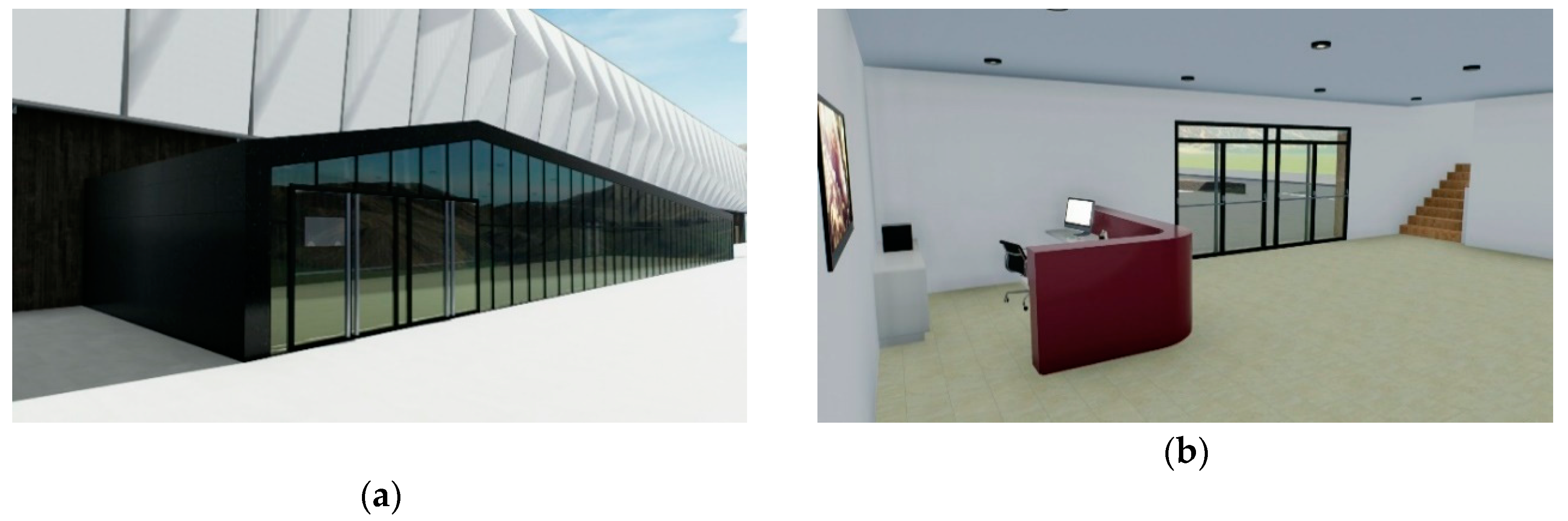
The gym area has a single entrance that gives access to the reception, two offices, a toilet, and a cafeteria. Behind these will be the barriers that give access to the gym area (
Figure 13).
On the ground floor there is the cafeteria that will be for all the public, since it is located before the access barriers to the gym. This will have a parquet floor and one of the walls with exposed brick cladding. It will also have a bar with stools and a table area. Through a door behind the bar there is access the kitchen and from there, to the warehouse (
Figure 14). It will also have toilets for women, men, and for disabled persons.
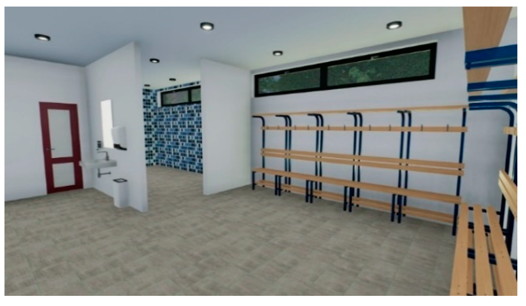
After the barriers, there is access the members’ part of the gym where we find a lobby that gives access through a staircase or two elevators to the upper floor of the gym and a corridor that leads to the changing rooms. The changing rooms are composed of a main area with lockers and benches to be able to change and store belongings (
Figure 15). At the bottom of this area the sinks are located and from this area you can access a corridor of toilets and another of showers. In this case, they are individual showers with a shower tray in each. The changing rooms will have a marble floor like the rest of the ground floor, with the exception of the toilets, which will have a porcelain stoneware floor. The covering of all the walls will be with tiles.
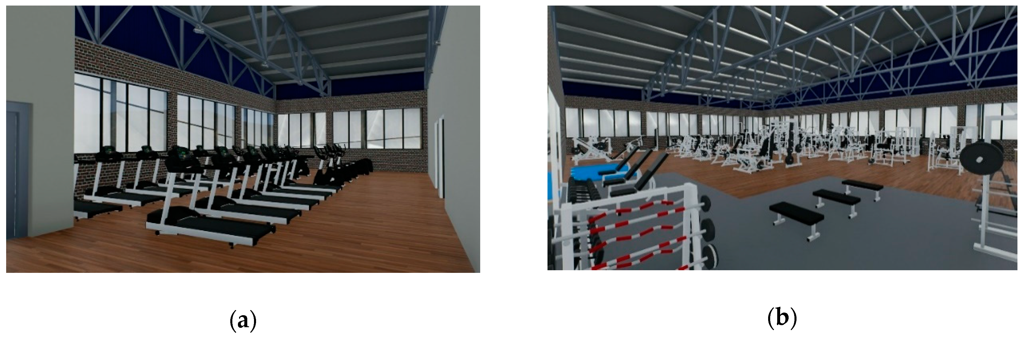
The upper floor of the gym consists of a bodybuilding training area, a cardio area, yoga room, spinning room, and toilets. The floor is parquet throughout the floor except for the toilets, which is porcelain stoneware, and an exposed brick cladding has been decided for the walls. The bodybuilding area will have a section where a rubber floor will be used above the parquet to avoid damaging it, since this area will be used for lifting dumbbells (
Figure 16).
The cardio area will be composed of elliptical bikes, stationary bikes, and treadmills. The bodybuilding training area will instead have machines dedicated to strength training of different muscle groups and, in addition, will have an area with benches, dumbbells, and bar weights so as to be able to carry out all kinds of training, not only with machines. The yoga room will be a room dedicated to the practice of sports such as yoga or Pilates, while the spinning room will be a place with exercise stationary bikes to carry out this sport (
Figure 17).
3.6. Exterior
According to the General Urban Planning Plan (PGOU), the pavilion will be equipped with exterior green areas and three well-differentiated sectors have been created for this (
Figure 18).
On the one hand, we have the green sector located in the eastern area of the sports center. This is characterized by being an open place where we find two large areas of lawn where there are also some trees which serve as shade. The function of this first area is to provide the site with an open place where you can lie down or sit directly on the grass and be able to carry out leisure activities (
Figure 19).
On the opposite side we have the West green sector. This one, unlike the other, is a more closed place. This is because we want to give a feeling of welcome. For this we have created several areas with geometric shapes where you can sit. In addition, the concept of height and shapes has been played with, having been created with different heights achieved by a succession of steps on which to sit. Besides, this sector has floor lighting along the perimeter of the four geometric fields, which makes it very attractive (
Figure 20).
Finally, in the southern sector of the plot we find a large square that gives easy access to the pavilion and gym. In this area, the pond on the right side stands out especially, which also offers a good place to sit. In addition, this pond has a statue specially designed with a sports motif, specifically of two badminton players playing. With this statue, the height of the water is used as part of the play with one of the players flushing on it, giving the impression that the pond itself is the badminton court (
Figure 21).
3.7. Facilities Design
The Industry Foundation Classes (IFC) standard achieves the exchange of information and exchange between different information systems and interested parties, facilitating collaborative construction in construction projects [
39]. The IFC standard is developed by building SMART, which is an international organization for OpenBIM, and its mission is to “enable interoperability between industrial processes from all different professional domains in civil engineering projects, by allowing that computer applications used by all project participants are shared and exchanged project information”. In the IFC standard, there are four layers (resources, core, interoperability, and domain), and many types, entities, rules, and functions are defined in EXPRESS data specification language to describe actors, process, control, resource, product, etc. [
40].
The design and calculation of the facilities will be carried out by means of the use of the CYPECAD MEP
® software. This implies that it is necessary to transfer the model designed in Edificius
® to other software. For this, the IFC format will be used, which will allow all information and building modeling to be transferred to CYPECAD MEP
® properly (
Figure 22). The design and calculation of the facilities depend on the country’s regulations and for this we must ensure that they are implemented in the MEP program.
Once the facilities have been designed and calculated according to the normative specifications of the corresponding country, the interferences between facilities within the model are analyzed and verified before beginning real construction in a virtual way in OpenBIM, so as to avoid problematic situations.
Figure 23 show images of the model at IFC with air conditioning and plumbing installations.
Figure 24 shows the interferences between facilities within the model analyzed and are verified before beginning real construction in a virtual way in OpenBIM, so as to avoid problematic situations (intersections between ducts of different installations). OpenBIM is crucial at this point in the project design, as it allows the exchange of information between different disciplines in real time. In the BIM-MEP environment, an estimate of construction costs and facility costs can be established, making it possible to control them efficiently, as previously mentioned.
Figure 25 shows the solar thermal installation attached to the roof of the IFC model and
Figure 26 shows the ventilation ducts.
One of the main functions of the BIM methodology is the interconnection and fluid exchange of data between different stakeholders that intervene at any time of the process. It is about having all the information and available work in the same place, that is, an environment shared and accessible by all. This environment which we have described is the OpenBIM, an environment that allows easy data management, and allows information to be available in real time. In addition, this methodology allows a better management of the entire process and of time. Another great advantage of the OpenBIM methodology is to be able to share both the model and different associated data using an open standardized format such as the IFC format, allowing different programs to make use of the information, which has an impact on reducing time. This is another of the advantages of this methodology since the reduction of time will also finally have an impact on monetary savings. In general, OpenBIM seeks to promote the compatibility and interconnection between different tools and agents by combining them in the same environment, allowing savings in time and costs, as well as easier and better project management throughout its life cycle.
4. Discussion
With the presentation of this empirical case study, BIM software has been applied for building design, MEP software has been applied for facilities design, and the interaction between both BIM-MEP work environments has been analyzed. Finally, the objective has been achieved. It is demonstrated that the flow of project information between both environments is possible under the IFC format.
BIM allows not only a better modeling of the building but also a better design of infrastructure, unlike conventional methods where we only had lines without properties. BIM provides us with a design where each element has parameterizable values and each one of the elements interacts with the other, enabling us to see the problems before the execution of the project, a situation that we could not solve with traditional methods.
The BIM environment is an interrelated and connected environment where each change made in one part affects the entire environment and is automatically updated, unlike in conventional methods where a change in one part of the model, must be applied to each one of the affected parties. This is a huge time-saving factor, in addition to making the design work much easier by being able to make changes as the project progresses.
All the information collected in the BIM programs will be ordered and classified by families, which will allow it to be easily obtained afterwards.
Through formats such as IFC, it is possible to exchange information between different software, but presently this part is not fully developed, since in our case study it was possible to see how errors occurred in the model when passing the project information through IFC from Edificius® to CYPECAD MEP®.
The choice of these software is due to the fact that both have an intuitive interface and are easy to use. Edificius® presents a good level of rendering in real time (video, photo), and allows objects with different extensions to be imported into the model. In addition, Edificius® allows BIM 4D time planning studies and BIM 5D cost studies to be carried out.
This implies a loss of time by having to correct each of these information transfer errors, that is, one of the main advantages, which was saving time, would already be lost. One of the causes of these errors when transferring information through IFC model from one software to another, could be that both software belong to different software companies, that is, to prevent this type of problem from occurring, it would be advisable to work with the same software company that can supply all the computer tools necessary to develop a project. In addition, it would also be convenient if there was a bilateral and not unilateral interaction and exchange of information, in order to obtain better use of the BIM environment. As for the interaction by means of the CAD format between AutoCAD® and Edificius®, it has been optimal, there being no problem when using the plans previously designed in CAD as templates for the design of the building in Edificius®.
Edificius® offers the possibility within the software itself of making renderings of the model, thus saving us from having to resort to other software to be able to carry out this part. Nowadays it is essential to generate marketing to present a project before investors or promoters, especially if it is of an architectural type, since it offers us a realistic vision of how the project would be once executed. The software’s rendering tool works correctly and has allowed us to obtain results like any other software dedicated exclusively to this task.
Edificius®’s direct interaction with programs such as SketchUp® allows us to design 3D objects with this other software and introduce them quickly and efficiently into the other. In order to visualize and present the project, it is necessary to introduce 3D objects into the model that give greater realism to it; an easy-to-use tool is the SketchUp® program. This allows us to create 3D objects and there are even exchange communities of designs, which provide us a large library in order to decorate the BIM model.
Regarding the use and creation of materials, Edificius® offers a wide library of materials to use that are already parameterized with all the necessary data, on the other hand, if there was no material that met our requirements, it could be created and be given the necessary values to have a suitable parameterization of it.
The final result of the project has largely met expectations and a sports pavilion has been modeled in less time than with traditional tools, demonstrating that BIM tools are the future in terms of the design and modeling of architectural structures (
Figure 27).
5. Conclusions
Some benefits found in adopting BIM and MEP, using OpenBIM in projects are:
Design improvement, time saving, and cost reduction;
Ease of information exchange;
Promotion of collaboration;
Decrease in errors;
Increased sustainability and labor market improvements;
Improved productivity and competitiveness.
BIM presents an optimal work environment to carry out projects in less time, with greater ease and saves costs. Although nowadays its use is already a reality, is quite widespread and growing among the most developed countries such as the United States or part of the European Union, we still find that it is not fully developed and it is necessary to improve, especially in the area of information exchange, a very important part of the BIM environment.
In addition, today there is a need for greater dissemination and training in this type of environment, since there is still a great lack of knowledge among part of the community, many of them clinging to conventional tools and delaying the change.
In terms of aesthetics, it is a very powerful tool, since by allowing us to work on a 3D model, we can see at all times the appearance of the project and even the visual interaction with the environment that surrounds it.
Being able to work in the same environment in a group it allows all types of agents to work in different parts of the project, but in the same environment, implying that they will all be working under the same standards, and therefore, there will be optimal interaction between all parts. This leads to saving time and even to an optimization of the materials to be used on site and consequently to cost savings.
In addition, one of the most recently introduced elements in BIM, BIM 7D, which deals with the maintenance and life cycle of the work, allows a better management of the project for the future and its life, being able to avoid future problems in the building due to not having planned adequate maintenance of it. It also facilitates the work on the construction site in case of a demolition, when it reaches its end, or an adequate reuse of it.
The main characteristic of OpenBIM technology and its main advantage is that it is based on standard open and public exchange formats (IFC), so that the content of the BIM project is not linked to any specific application or software. Furthermore, thanks to the use of such exchange formats, the specific applications used to solve the different aspects of a project (structure, sanitation, electricity, etc.) do not have to be linked to a single software manufacturer either. Although there is no single BIM tool, neither a single MEP tool, this work is a practical example of how to integrate students or professionals into the IFC workflow for the application of OpenBIM technology.
To finish, and in summary, the proposed workflow allows two very important issues, which are clearly differentiating: There is the interaction between the different MEP disciplines in the BIM model, through IFC files to introduce electrical and mechanical installations, etc., and on the other hand, it allows the content of the BIM project to be unlinked from applications that have been used to develop it, thus guaranteeing the durability and accessibility of the developed work.


