Abstract
Passive energy dissipation systems are one of the most resilient solutions to mitigate the seismic risk of structures. In case of strong motions, they can confine the eventual damages into easily replaceable anti-seismic devices. The performance characteristics of nonlinear displacement dependent devices (NLD) shall be defined by the force-displacement cyclic behavior, as well as the expected number of cycles related to both the duration of the earthquake and to the fundamental frequency of the structural systems. The aims of this paper are the comparison between the dynamic results of two different experimental campaigns performed on NLDs included in dissipative bracing systems and the assessment of the reliability of quasi-static testing procedures proposed by current seismic codes for type tests and factory production control tests. The number of cycles under the design earthquake of hysteretic dampers were experimentally evaluated through shaking table testing. Two experimental case studies of a two-story steel frame and of a three-story post-tensioned timber frame both with bracing systems including flexural steel dampers, hysteretic dampers (HDs), and U-shaped flexural plates (UFPs) respectively, were analyzed. Controlled-displacement tests of NLDs were performed considering quasi-static loading procedures specified by codes. Shaking table tests were carried out considering almost the same seismic sequence composed by a set of seven natural earthquakes at increasing peak ground acceleration (PGA) levels. More than one hundred inelastic cycles were experimentally recorded from dynamic tests before the failure of devices in both cases. In line with American standards testing requirements, the number of cycles at the design PGA level, estimated from shaking table tests and from non-linear dynamic analyses, shows a decreasing trend with the increase of ductility demand.
1. Introduction
The seismic resilience is defined as the capability of a structural system to maintain an appropriate level of functionality during and after a strong earthquake and the capability to restore its initial condition within a short time period. Passive energy dissipation systems are considered one of the most efficient and cost-effective solutions to mitigate the seismic risk for new and existing structures minimizing damage to the structural and non-structural elements. The installation of these systems allows to dissipate a large portion of earthquake input energy confining the eventual damage in structural replaceable anti-seismic devices, limiting cost and interruption of human occupancy and activities, with evident economic and social benefits. In the last decades the research and development of earthquake resilient performance of buildings equipped with dissipative systems achieved significant progress [1,2,3,4,5].
Energy dissipation dampers are classified in two main categories due to a velocity dependent or a displacement dependent mechanism. In displacement dependent damping devices, the force response is primarily a function of the relative displacement between each end of the device. The response is substantially independent by the relative velocity between each side of the device and the excitation frequency. Non-linear displacement dependent devices in which the hysteretic energy is dissipated through the yielding of steel material attracted more attention from civil engineers related to their cost-effectiveness and ease of fabrication, the symmetric and stable hysteretic behavior, better low-cycle fatigue property, long-term reliability, and resistance to the environmental actions. Aging is of least concern because corrosion may only slightly reduce the section geometrical properties and an inspection and maintenance program should eliminate the problem.
The development and testing of hysteretic steel dampers for the seismic protection of structures started in 1970s on mild steel devices of solid cross section characterized by high stability at high levels of plastic strain. A flexural metallic damper initially proposed and experimentally tested by Kelly et al. [6] was designed to provide energy dissipation between structural walls and adjacent floors. Thereafter, several metallic dampers such as torsional or flexural beam [7], single-axis dampers [8], U-strip [9], buckling-restrained brace (BRB) [10], were developed and tested for implementation in structures [11,12,13,14,15,16,17,18,19].
Successful experimental and real applications widely demonstrated the effectiveness and reliability of hysteretic steel dampers installed in various structural systems, such as connecting element between walls and frames [15], in coupled walls [16,17] and at beam–column and column–foundation connections of frames [18]. One of the fundamental parameters investigated to demonstrate the efficacy of metallic dampers is the number of cycles, which can be related to the capacity to dissipate energy for a given displacement and to the fatigue and eventual failure of the devices, leading to different level of damage to the structural system [19]. Several design procedures and various configurations of dissipative bracing systems incorporating replaceable metallic dampers have been developed for the seismic retrofitting of existing buildings and for the new buildings construction with different constitutive materials [20,21,22,23,24].
Traditional steel braces equipped with hysteretic dissipative devices were successfully used to reduce the seismic demand of existing reinforced concrete framed structures in [25]. Steel frames equipped with buckling-restrained axial dampers (BRAD) and externally connected to the façades of an existing building were considered in [26] in order to improve energy efficiency and earthquake-resistant performance. Crescent shaped braces (CSBs) were recently used for seismic retrofitting as hospital in order to connect the steel moment-resisting frames with two external reinforced-concrete cores [27,28,29,30]. CSBs are characterized by a geometrical configuration which is “ad hoc” defined in order to provide the structure with prescribed multiple seismic performances, within the performance based seismic design framework. U-shaped hysteretic dampers included in a damping box located at the middle of a diagonal brace are proposed in [31] to improve the performance of moment-resisting frames. The experimental behavior of a self-centering timber brace that employs the resilient slip friction joint (RSFJ) for energy dissipation is investigated in [32]. Steel frame braced with tension-only pseudo-elastic nickel-titanium (NiTi) shape memory alloy (SMA) wires was developed in [33] for seismic retrofit applications.
Specific codes are adopted worldwide to regulate the use of these seismic-resilient devices. AASHTO Guide Specification for Seismic Isolation Design [34] was the first code which established rules for the dimensioning and the use of anti-seismic devices. This document was firstly focused on isolation systems, then recommendations to energy dissipating devices were also extended. Nowadays the regulation of anti-seismic devices has been included in national standards, as example the Italian seismic code NTC 2018 [35], the European Standards EN 15,129 [36] and the American Standards ASCE/SEI 7-10 [37] and guidelines such as the American FEMA 461 [38]. These codes specify the performance requirements of nonlinear displacement dependent device in order to reproduce the actual working conditions of the devices, covering all the stages of the life cycles. In general, in case of metallic dampers the velocity has negligible influence and quasi-static tests can be carried out to establish their performance capability. The test procedure shall include the steps listed in the codes unless otherwise prescribed in the design specifications.
Based on the results of two experimental campaigns performed at the structural laboratory of University of Basilicata (Italy), in the present work the attention is focused on cyclic performance of steel flexural NLD dampers installed in V-inverted dissipative bracing systems considered for a steel frame (JetPacs project) [39] and for a post-tensioned timber frame (Pres-Lam project) [24,40]. Respect to previous papers the novelty of this study is the comparison of the complete seismic sequence of shaking table test results of two different experimental braced frame models including NLDs. The main objective is to assess the reliability of current seismic codes in terms of cyclic testing required for type tests and factory production control tests of NLD. In particular, hysteretic dampers (HD) considered for the steel braced frame (SBF) and U-shaped flexural steel plate (UFP) dampers used for the timber braced frame (TBF) have been analyzed. The capability of both devices to dissipate energy is due to the nonlinear behavior when stressed beyond elastic limit, moving the yielding point along the flexural plates.
Quasi-static cyclic tests of both NLDs were performed to characterize the force-displacement behavior of dampers using testing protocols proposed by the American guidelines and European codes. Then, the experimental results of the shaking table tests performed on both specimens are compared in terms of global seismic behavior of the structures and local response of dampers. Almost the same random seismic sequence composed by over 20 consecutive seismic inputs, obtained from the same set of 7 natural earthquakes at various intensities, has been considered for both frame models. In this paper, the experimental results have been investigated in terms of number of cycles to failure of HD and UFP devices, i.e., the number of fatigue cycles at which the rupture of a device happened. The number of cycles estimated from earthquakes at the design level (PGA 100%), considering shaking table tests results and non-linear dynamic analyses, was compared with quasi static cyclic testing requirements provided for NLDs by Italian seismic code, and European and American Standards and guidelines. The results show a decreasing trend of number of cycles with the increase of ductility demand, in line with American standards testing requirements.
2. Code Requirements for Displacement Dependent NLD
Steel devices typically show a stable hysteretic behavior characterized by yield capacity that is well known as function of the steel type considered and that can be determined with simple material tests. The conformity of mechanical characteristics of NLDs with the performance requirements shall be verified by specific tests representing the working conditions and constraints of the device. The Italian and European seismic codes NTC 2018 [35], EN 15,129 [36], and American Standards ASCE 7-10 [37] use different empirical approaches for determining the testing protocols for quasi-static tests of the devices. Moreover, several guidelines suggest different loading histories for eventual incorporation in existing standards for the seismic design. FEMA 461 [38] suggests quasi-static testing protocols as an interim basis for testing of building components, it is not intended for seismic performance qualification testing to satisfy the requirements of building codes.
The displacement at the collapse prevention limit state d2 by NTC 2018 [35], corresponding to the design displacement dbd including the reliability factor γx × dbd by EN 15,129 [36], or the displacement at the maximum credible earthquake dMCE by ASCE 7-10 [37] shall be considered for the design and analysis of structures with energy dissipative systems. The mechanical tests of the devices shall be carried out by imposing cyclic deformations according to the schedule and the procedures indicated as type tests (TT) and factory production control tests (FPCT) of devices. All devices shall be qualified under the responsibility of the manufacturer, according TT procedure provided by codes. Test specimens shall not be used for construction, unless they are approved by the responsible for design of the structure and meet the required qualification documentation, the geometric verification, and dimensional tolerances as well as the FPCT tests for all types of devices. Testing on devices must be performed and certified by a laboratory equipped with adequate competence, equipment, and organization.
Type tests (TT) shall be carried out on at least one specimen in order to reproduce the actual working conditions of the devices given in the design specifications. The specimens shall be loaded so as to produce the same stresses and strains as those experienced during the response of the structure to the design earthquake up to a maximum displacement, at least equal to ±dbd [36]. For type tests the NTC 2018 [35] refers to EN 15,129 [36] (series TT [EN 15129] of Figure 1a). Increasing amplitude cycles shall be imposed at 25%, 50% and 100% of dbd applying five cycles for each intermediate amplitude and at least ten cycles for the maximum amplitude. Moreover, a ramp test shall be performed for the static evaluation of the failure displacement up to a displacement not less than the maximum displacement taking into account the partial factors γb × γx × dbd. The reliability factor γx, equal or greater than 1, depends on the role that the devices play in the stability of the construction after the earthquake. The partial factor γb, not less than 1.1, is related to action effects other than seismic which can affect the initial configuration of the device. According to NTC 2018 factory production control tests (FPCT) of devices shall be always carried out on the devices prior to their installation on at least 20% of the supply, and however not less than 4 devices [35]. Quasi-static test shall be performed imposing five cycles at the maximum displacement ±d2 [35] (series FPCT [NTC 2018] of Figure 1b). Differently, Eurocode [36] reduces the devices number to tests to at least 2% with a minimum number of one device with the same increasing amplitude cycles applied for TT (series FPCT [EN 15129] of Figure 1b).
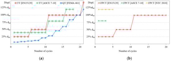
Figure 1.
Sketch of deformation-controlled loading history proposed by main codes and guidelines for (a) type tests (TT) and (b) factory production control tests (FPCT).
ASCE 7-10 [37] requires prototype tests (TT) on at least two prototype devices at 33%, 67%, and 100% of the displacement dMCE applying ten, five, and three cycles, respectively (series TT (ASCE 7–10) of Figure 1a). Production tests (FPCT) shall validate the nominal properties by testing 100% of the devices for three cycles at 67% of the dMCE at a frequency equal to 1/(1.5 × T1) (series FPCT (ASCE 7–10) of Figure 1b). On the other hand, FEMA [38] describes a recommended loading history appropriate for hysteretic testing if a single specimen will be used to quantify all damage states. The loading history consists of repeated cycles of 10 step-wise increasing deformation amplitudes until the targeted deformation amplitude (ddb) is reached. Two cycles at each amplitude shall be completed. It highly recommends performing an additional monotonic test to provide a baseline for estimating the cumulative damage effect at each damage state (series QT (FEMA 461) of Figure 1a).
Figure 1a,b compare conceptual diagrams of the loading history required for type tests by the European codes (TT (EN 15129)), by American Standards (TT (ASCE 7-10)) and that recommended for quasi-static Tests (QT) by American guidelines (QT (FEMA 461)) and for factory production control tests by the European code (FPCT (EN 15129)), by American Standards (FPCT (ASCE 7-10)) and by the Italian code (FPCT (NTC 2018)).
3. Experimental Case Studies
In this paper two experimental case studies of shaking table testing performed on two different frame models both equipped with V-inverted dissipative bracing systems have been considered. The first one was carried out within the Jet-Pacs project (2008–2010), supported by several partners from different Italian Universities which in turn developed different energy dissipation devices based on different materials and principles [39]. The second one within the Pres-Lam project (2013–2019), in collaboration with University of Canterbury [24,40]. A photographic view of both experimental frames tested on the same single degree of freedom shake table facility available at the structural laboratory of the University of Basilicata (UNIBAS) is shown in Figure 2. Both models were three dimensional, 2/3 scaled, with an inter-story height of 2 m and the rectangular plan layout of 4 m by 3 m, with single bay in both directions.
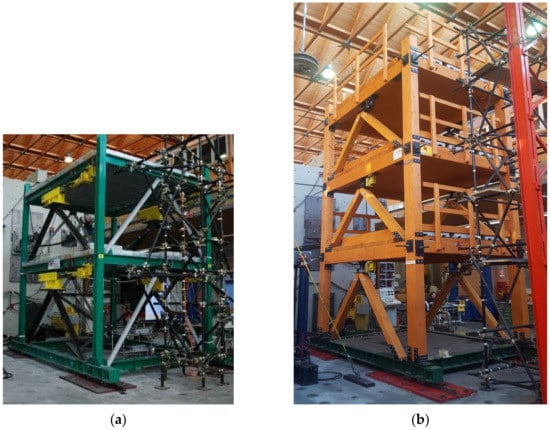
Figure 2.
Experimental case studies for shaking table testing: (a) steel braced frame Steel Braced Frame (SBF) model (b) post-tensioned timber braced frame Timber Braced Frame (TBF) model.
The Jet-Pacs experimental model consisted of a two-story steel braced frame (SBF) with four dissipative braces, two for each side, along the testing direction (Figure 2a). Steel profiles IPE 180 and HEB 140 of steel grade S235 were used for beams and columns respectively and the floors were made of a 100 mm thick steel-concrete slab.
The Pres-Lam specimen experimental model consisted of a three-story post-tensioned timber braced frame (TBF) with six V-inverted dissipative bracing systems, inserted within the bays of the two parallel frames along the test direction (Figure 2b). The frame was post-tensioned at the beam–column connections through a single 26.5 mm diameter steel bar, crossing the beam in longitudinal and transversal directions. Cross sections of 320 mm × 200 mm for columns, 305 mm × 200 mm and 240 mm × 200 mm for primary and secondary beams made of Glulam grade GL32h were used. The floors were realized by 150 mm thick solid timber panels.
Models were designed according to the European seismic codes [41,42]. The SBF represents a residential steel building while the TBF represents an office structure with a rooftop garden. Additional masses (concrete blocks) were placed on each floor of both experimental models, to account for non-structural dead loads and the live loads, as well as the contribution due to the mass-similitude scaling [43]. Story masses of experimental models are summarized in Table 1.

Table 1.
Seismic masses for steel (SBF) and timber (TBF) braced frame.
NLDs considered for both projects were based on the dissipative capability of flexural steel plates with hysteretic behavior. Hysteretic dampers (HD) of steel grade S235 shown in Figure 3a [14] were considered for the SBF model and mounted on the top of two stiff steel chevron braces (HEA100) of steel grade S235 at each story (Figure 3b). The bolted connection between the HD and the braces ensured the rigid connection. Two additional V-inverted steel braces (UPN 80) were placed orthogonal to the excitation as a safety system during testing.
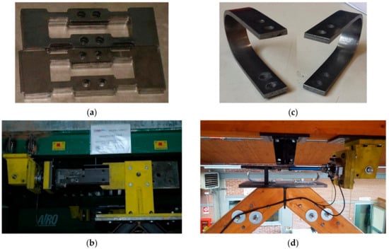
Figure 3.
Detail of (a) hysteretic dampers (HD) devices and (b) of dissipative bracing connection of SBF; (c) Detail of UFP devices and (d) of dissipative bracing connection of TBF.
Two U-shape flexural plate (UFP) devices of steel grade C60 shown in Figure 3c [44] were used for each dissipative brace of the TBF model, placed on the top of the V-inverted timber rods with cross section of 160 mm × 180 mm of Glulam grade GL24h linked through bolted connections (Figure 3d).
Braced models were designed to remain in the elastic range without damages while hysteretic devices yield is provided to dissipate earthquake energy. The NLD dampers at each story were dimensioned through displacement-based design procedure, considering different target design drift at the same design earthquake as shown in Figure 4. The design response spectrum was defined according to Eurocode [42] for high seismic zone and medium soil class type B, considering a peak ground acceleration of 0.44 g. To ensure consistency with the scale of both experimental models, the recordings were scaled down in time by a factor of 1/√ (3/2). A target drift of 0.5% and of 1.25% were assumed in the design of SBF and TBF, respectively. The equivalent elasto-plastic behavior of the SBF is represented in Figure 4a as the combination of a linear elastic element, which characterizes the equivalent bare frame, and an elasto-plastic element which schematizes the equivalent dissipative bracing system [14]. The equivalent flag-shaped behavior of the TBF model is reported in Figure 4b, it consists of a combination of a bilinear elastic element of the post-tensioned timber frame [45] and an elasto-perfectly plastic element of the hysteretic bracing system [44]. As can be seen from Figure 4, experimental case studies are characterized by different stiffness of the bare frame while the equivalent bracing systems obtained from design have almost the same strength and ductility (μd = 5 for the SBF braces and about μd = 4 for the TBF braces).
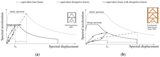
Figure 4.
Idealized non-linear response from displacement-based design of (a) SBF and (b) TBF.
Numerical models of both braced frames were built based on the lumped plasticity approach which combines the use of elastic elements (beams, columns, and braces) with linear or rotational springs representing plastic deformations in the system (hysteretic devices, post-tensioning, and rocking mechanisms) and calibrated against the experimental outcomes. NLDs were modelled using nonlinear Bouc–Wen [46,47] link elements with hysteretic behavior evaluated by characterization tests. Table 2 reports the main dynamic properties of both braced models in terms of the periods of the first modes of vibration in the direction of loading obtained from experimental (Texp) and numerical (Tnum) results. As shown in Table 2 a good agreement between the experimental [14,40] and numerical [14,48] dynamic characteristics was found for both models. More details about numerical modelling and simulations of SBF and TBF can be found in Di Cesare et al. [14,24,48].
Table 2.
Dynamic properties of the SBF and TBF braced model.
4. Quasi-Static Tests of NLD Devices
Quasi-static tests have been performed to characterize the force-displacement behavior of HD and UFP steel dampers, as representative of the devices installed at each story of the SBF and TBF models. Figure 5a,b show the controlled-displacement testing apparatus available at University of Basilicata to test the HD [14] and UFP devices [44], respectively. A load cell attached to the loading actuator and linear potentiometers were used to record forces and displacements of dampers. The number and relative amplitudes of the excursions should represent, on average, the history of the loading at each damage state that is to be quantified. This is not possible because lower damage states are associated with smaller earthquake intensities and higher damage states are associated with larger earthquake intensities. A loading history complete for all damage states was used for the single specimen.
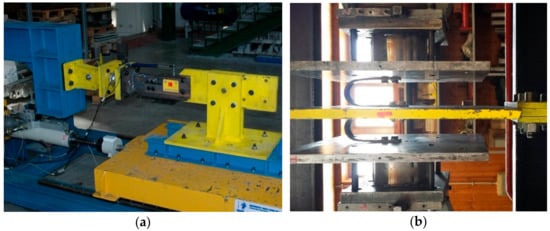
Figure 5.
Quasi-static testing set-up of (a) HD and (b) U-shaped flexural plates (UFPs).
The experimental force-displacement responses of HDs and UFPs are shown in Figure 6. normalized considering the experimental yielding force (Fy) and displacement (dy) obtained from experimental tests of each single device (see also yield point indicated in Section 5.2). The reference design ductility values were μd = 5 for HDs and μd = 4 for the UFPs. The quasi-static testing procedure used for HDs (Figure 6a) followed the loading protocol required for TT by EN15129 [36] (see Figure 1) with five cycles at μ = 1.25 and μ = 2.5 and ten cycles at μ = 5. A monotonic ramp test up the amplitude of μ > 5 was also performed. Different loading testing criterion was considered for UFPs (Figure 6b) following the interim protocol for quasi-static cyclic testing proposed by FEMA 461 [38] (see Figure 1). In this case the loading protocol was composed by two cycles at increasing amplitudes with five steps in the elastic range and five steps at ductility values of μ = 1, μ = 1.8, μ = 2.5, μ = 3.5, and μ = 4. A monotonic ramp test up the amplitude of μ > 4 was applied also in this case. As can be observed in Figure 6, the force-displacement results obtained by quasi-static tests, exhibited a stable hysteretic cyclic behavior without failure over the design displacement for both HDs and UFPs.
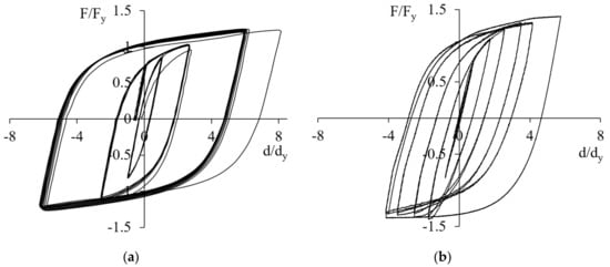
Figure 6.
Experimental force-displacement response from quasi-static testing of (a) HD and (b) UFPs.
5. Dynamic Response of Braced Models
5.1. Seismic Sequence
The same seismic sequence was considered as the base input for shake table testing of both experimental case studies. The time history of input acceleration is shown in Figure 7. The seismic sequence with duration of about one thousand seconds is composed by over 20 consecutive seismic inputs, collected from a set of seven natural spectra-compatible earthquakes selected from the European strong-motion database, at increasing intensities from 10% to 100% of PGA. The normalized elastic acceleration spectra of the selected earthquakes are reported in Figure 8 compared with the mean spectrum (medium) and the design spectrum (by code). A summary of the seismic inputs sequence performed for SBF and TBF models are reported in Table 3. Due to different performances required at the intermediate and ultimate damage states of diverse experimental models, slight differences of the applied PGA levels can be observed. The complete set of earthquakes was performed at 50% of PGA for TBF model and at 75% of PGA for SBF model.
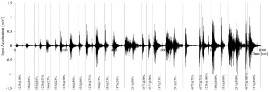
Figure 7.
Seismic sequence for shaking table testing of both experimental braced frame models.
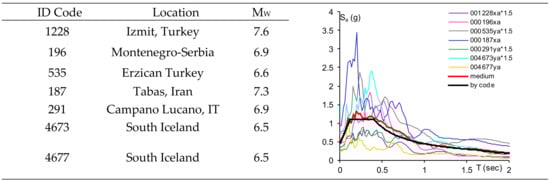
Figure 8.
Spectra-compatible earthquakes selected for the input sequence of shaking table tests.
Table 3.
Detail of the earthquakes sequence applied for shake table testing of steel (SBF) and timber (TBF) braced frame models.
5.2. Shaking Table Testing Results
The seismic response of braced frames and the local response of NLD obtained from shaking table tests of both case studies are described in this section. Global and local responses of both braced frames were recorded by more than 50 sensors, including load cells, horizontal and vertical accelerometers, and displacement transducers connecting the frame to an external reference structure to record the global seismic behavior and displacement potentiometers for recording the force-displacement behavior of the energy dissipating devices at each story [14,40].
The time-histories of global drift of the SBF and TBF models are shown in Figure 9. Figure 10 shows the time-histories of demand ductility up to the devices breakage occurred during the test with earthquake input 187 at 100% of PGA level at the second story for HD and at the first story for UFPs. In case of SBF model an interlock limit was activated and the test was stopped for safety reasons.
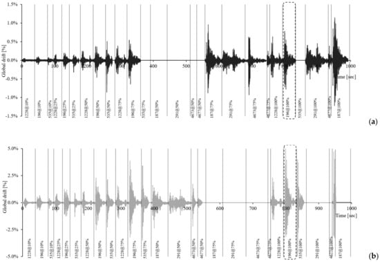
Figure 9.
Time history of global drifts of (a) SBF model and (b) TBF model.
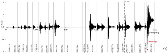
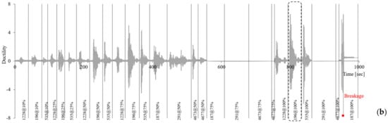
Figure 10.
Time history of the ductility of dampers of (a) HDs at the second story of SBF model and (b) UFPs at the first story of the TBF model.
Both braced frames exhibited a complete re-centering capability, with negligible residual inter-story drift and displacements of dampers accumulated during the tests. Up to 50% or 75% of PGA level the global drift reached the design drift, for most severe earthquakes, of both experimental models (0.5% for the SBF model and 1.25% for the TBF model) and the ductility of NLDs slightly exceeds the design values (µ = 5 for the HD devices and µ = 4 for the UFP devices).
Figure 11 shows the global response of SBF and TBF models in terms of the time history of the main seismic key indicators (base shear, top displacement, top acceleration, and inter-story drift) for the seismic input 196 at 100% of PGA level. The experimental results show that the base shear recorded by the dynamic actuator of the shaking table and the top acceleration of both the experimental models are of the same order, differences are related to different total mass values of the experimental models. On the contrary, the top displacements and first story drifts are not comparable due to the higher stiffness of the SBF model. The base shear versus top displacement responses highlighted the hysteretic behavior of the SBF model (Figure 11a) and the typical flag-shaped behavior of the post-tensioned TBF model, as emphasized in Figure 11b from two cycles at highest displacement.
Figure 11.
Global seismic response for earthquake input 196 at 100% of PGA in terms of time histories of base shear, top displacement, top acceleration, and 1st story drift and base shear vs. top displacement of the (a) 2-story SBF and (b) 3-story TBF.
Force-displacement cycles of HD and UFP dampers placed at each story of the bracing systems of the SBF and the TBF models obtained from shaking table testing for the seismic input 196 at 100% of PGA are compared in Figure 12. The force-displacement curved have been normalized based on the yielding force and displacements obtained by the experimental characterization tests (yield points are indicated in Figure 12). In both cases the NLD dampers showed excellent hysteretic response without significant degradation in strength and stiffness. The force-displacement behavior of HDs and UFPs reflected the behavior of the bare frames with similar of strength due to similar values of story masses (see Table 1) and different values of stiffness (see Figure 4), with HDs stiffness higher than that of UFPs.
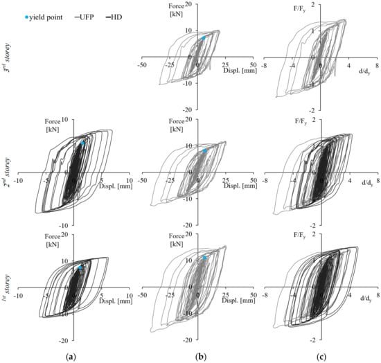
Figure 12.
Local seismic response for earthquake input 196 at 100% of PGA in terms of Force-displacement cycles of NLD devices: (a) HDs for the SBF and (b) UFPs for the TBF; (c) comparison of normalized behavior of HDs and UFPs.
The displacement time history and the force-displacement behavior of devices of the last test of the seismic sequence (187 at 100% of PGA), during which the failure condition for fatigue was reached by both HDs and UFP, are shown in Figure 13. The use of dissipative bracing system has permitted to achieve a resilient seismic performance of both experimental models without observing structural damages or post-tensioning losses under the seismic sequence composed by more than 20 earthquakes. As shown by photos of Figure 13, the rupture occurred through fracture of the yielding section at ductility values higher than the design ones.
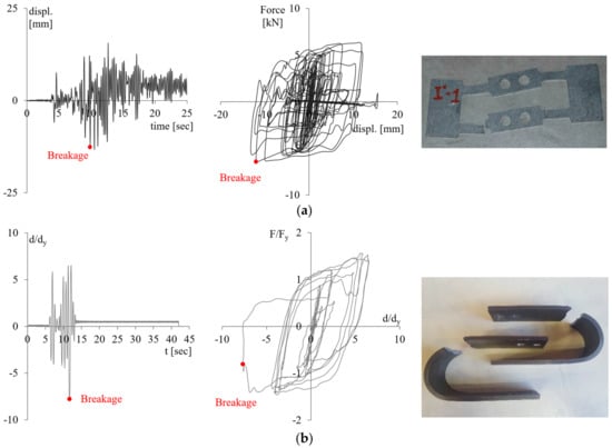
Figure 13.
Time-history of displacement and force-displacement cycles for seismic input 187 at 100% of PGA level and photos of the rupture of (a) HD at the second story and (b) UFP at the first story.
The estimation of the total number of cycles at different ductility levels obtained for the second story HD and first story UFP dampers from the experimental testing sequence has been summarized in Table 4. In the table, the mean values of number of cycles considering all earthquakes and the value of the standard deviation, representing the measure of the dispersion of the data, are also reported. The estimation highlighted a high number of cycles at low ductility values (up to µ = 2) spread out over a wide range, while at higher ductility values (µ > 2) a reduced number of cycles was recorded with low dispersion. The number of cycles estimated at the design ductility and at higher values (µ ≥ 5 for HDs and µ ≥ 4 for UFPs) resulted significantly lower than the minimum number of testing cycles required by codes both for TT and FPCT. For both HD and UFP devices the failure occurred during the stronger earthquake input considered, after more than 100 cycles sustained over the elastic range.
Table 4.
Number of cycles of HD at the second story and UFP dampers at the first story from all seismic sequence.
5.3. Number of Cycles of NLDs from Design Specificatons
Figure 14 shows the estimation of the number of cycles of the first story HD and UFP devices of the SBF and TBF models under the design earthquakes (100% of PGA) as a function of different ductility demands. In order to consider the complete set of ground motions the number of cycles estimation was evaluated considering the available dynamic experimental results (grey bars) and nonlinear numerical analysis (blue bars) for both HD (Figure 14a,c) and UFP (Figure 14b,d) devices, respectively. As can be observed the number of cycles at each ductility level of HD and UFP varies between the earthquakes, depending on the characteristics of each ground motion. Figure 14e,f show the average value of the mean number of dynamic cycles from experimental and from numerical results (mean dynamic num-exp). As can be observed, a good agreement was found between the mean experimental and numerical number of cycles estimated for both HD and UFP devices, with slightly and acceptable differences. In both cases the number of cycles considerably decrease at increasing level of required ductility.
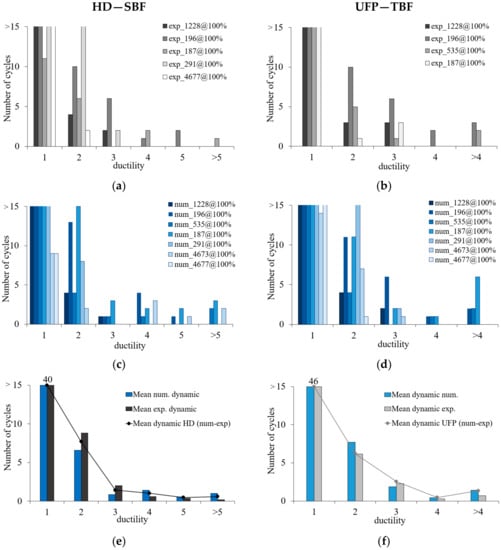
Figure 14.
Number of cycles vs. ductility demand during the design earthquakes (PGA 100%) obtained by experimental dynamic tests of (a) HD and (b) UFPs and nonlinear numerical analyses of the (c) HD of the SBF model and (d) UFPs of the TBF model and corresponding mean values for (e) HD and (f) UFPs.
The mean values of number of cycles estimated from the design earthquakes compared with the main code requirements for TT and FPCT testing of NLD devices standards [35,36,37,38] is shown in Figure 15 as function of the ductility demand. The mean number of cycles confirms the trend proposed by American standards and guidelines (TT (ASCE 7-10) and QT (FEMA 461)) for quasi-static characterization tests, in accordance with characterization tests performed on UFPs (see Figure 6b).
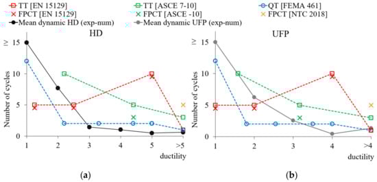
Figure 15.
Number of cycles estimated from experimental dynamic tests compared with the codes requirements for (a) HDs of the steel braced frame and (b) UFPs of the timber braced frame.
On the contrary the loading protocol required by European code EN 15129, also assumed by Italian code NTC 2018 and considered for the case of HDs characterization tests (see Figure 6a), seems to penalize devices excessively being not in good agreement with both experimental dynamic results. The minimum testing requirement for TT by European code [36] (TT (EN 15129)) overestimated the number of cycles at the design displacement (μ = 5 for HD and μ = 4 for UFP).
The minimum required for FPCT by Italian code (FPCT (NTC 2018]) at the maximum displacement ductility (μ ≥ 5 and μ ≥ 4 for SBF and TBF, respectively) is much higher than the corresponding average values observed for dynamic tests. Moreover, FPCT by Italian code is required for a minimum of four NLD dampers of the same type and size. A high number of device testing should be unnecessary due to the typically stable hysteretic behavior of yielding steel dampers. Moreover, stronger performance requirements than the actual seismic working condition of the devices could mean that the devices become unusable after testing besides higher costs required for testing procedures.
6. Conclusions
In this paper the experimental dynamic hysteretic behavior of different flexural steel dampers for dissipative bracing systems was investigated in terms of number of cycles at different ductility levels and compared with quasi-static cyclic testing requirements of main seismic codes and guidelines.
Two experimental case studies of a two-story steel frame and of a three-story post-tensioned timber frame both with dissipative bracing systems including flexural steel dampers, hysteretic dampers (HDs), and U-shaped flexural plates (UFPs), respectively, were considered in this study. The experimental braced frames were tested on the shaking table available at the structural laboratory of the University of Basilicata. The steel braced frame (SBF) and the post-tensioned timber braced frame (TBF) have different stiffness properties, designed based on DBD procedure at target design drift of 0.5% for the SBF and of 1.25% for the TBF. Controlled-displacement cyclic tests were carried out using different loading protocols in accordance with European code (EN 15129) for HDs and American guidelines (FEMA 461) for UFPs.
Shaking table tests were performed considering the same seismic sequence composed by a set of seven natural spectra-compatible earthquakes at increasing PGA levels. The main global key parameters highlighted that both frames responded with comparable base shears and top accelerations and with different displacements and drifts, due to the stiffness of SBF model higher than the TBF model. As expected, the global force-displacement behavior showed the hysteretic and flag-shaped responses of SBF and of the post-tensioned TBF, respectively. The HD and UFP dampers, provided ductile and stable performances with excellent dissipative capacity also when the displacement exceeded the design value. More than one hundred inelastic cycles were experimentally recorded from more than 20 earthquakes at increasing PGA levels before the failure of devices for both experimental models, with negligible residual drift and complete re-centering of seismic displacement without damages to the structural elements.
The number of cycles under the design earthquakes (PGA 100%) considerably decreases with increasing of ductility demand for both HD and UFP devices. This trend is in line with American standards testing requirements ASCE 7-10 [37] for prototype tests (TT) and in good agreement with the loading history suggested by American guidelines FEMA 461 [38]. The procedure imposed for type tests (TT) and for factory production control tests (FPCT) by European (EN 15,129 [36]) and Italian (NTC 2018 [35]) seismic codes significantly overestimated the number of cycles at the design ductility for both experimental case studies. Moreover, the number of devices required for FPCT by the NTC 2018 appear redundant compared with EN 15129, this becomes uneconomical especially in case of supply of few steel-based dampers unusable after testing.
Author Contributions
Conceptualization, A.D.C. and F.C.P.; methodology, A.D.C., F.C.P., and N.L.; experimental investigation, F.C.P., A.D.C., and D.N.; numerical analysis, A.D.C. and N.L.; data processing, N.L.; project administration, F.C.P. and A.D.C.; funding acquisition, F.C.P. and D.N. All authors have read and agreed to the published version of the manuscript.
Funding
This study was supported by RELUIS 2019–2021 project funded by the Italian Civil Protection Department.
Conflicts of Interest
The authors declare no conflict of interest. The funders had no role in the design of the study; in the collection, analyses, or interpretation of data; in the writing of the manuscript, or in the decision to publish the results.
References
- Bertero, R.D.; Bertero, V.V. Performance-based seismic engineering: The need for a reliable conceptual comprehensive approach. Earthq. Eng. Struct. Dyn. 2002, 31, 627–652. [Google Scholar] [CrossRef]
- Symans, M.D.; Charney, F.A.; Whittaker, A.S.; Constantinou, M.C.; Kircher, C.A.; Johnson, M.W.; McNamara, R.J. Energy dissipation systems for seismic applications: Current practice and recent developments. J. Struct. Eng. 2008, 134, 3–21. [Google Scholar] [CrossRef]
- Wang, J.; Zhao, H. High performance damage-resistant seismic resistant structural systems for sustainable and resilient city: A review. Shock Vib. 2018, 2018, 1–32. [Google Scholar] [CrossRef]
- Tirca, L.; Serban, O.; Lin, L.; Wang, M.; Lin, N. Improving the seismic resilience of existing braced-frame office buildings. J. Struct. Eng. 2016, 142, C4015003. [Google Scholar] [CrossRef]
- Christopoulos, C.; Filiatrault, A. Principles of Passive Supplemental Damping and Seismic Isolation; IUSS Press: Pavia, Italy, 2006; p. 480. [Google Scholar]
- Kelly, J.M.; Skinner, R.I.; Heine, A.J. Mechanisms of energy absorption in special devices for use in earthquake resistant structures. Bull. NZ Soc. Earthq. Eng. 1972, 5, 63–88. [Google Scholar] [CrossRef]
- Montuori, R.; Nastri, E.; Piluso, V. Advances in theory of plastic mechanism control: Closed form solution for MR-Frames. Earthq. Eng. Struct. Dyn. 2015, 44, 1035–1054. [Google Scholar] [CrossRef]
- Skinner, R.I.; Kelly, J.M.; Heine, A.J. Hysteretic dampers for earthquake-resistant structures. Earthq. Eng. Struct. Dyn. 1974, 3, 287–296. [Google Scholar] [CrossRef]
- Baird, A.; Smith, T.; Palermo, A.; Pampanin, S. Experimental and numerical study of U-shape flexural plate (UFP) dissipators. In New Zealand Society for Earthquake Engineering Conference; University of Canterbury: Christchurch, New Zealand, 2014. [Google Scholar]
- Watanabe, A.; Hitomi, Y.; Saeki, E.; Wada, A.; Fujimoto, M. Properties of brace encased in buckling-restraining concrete and steel tube. In Proceedings of the Ninth World Conference on Earthquake Engineering, Tokyo, Japan, 2–9 August 1988; Volume 4, pp. 719–724. [Google Scholar]
- Javanmardi, A.; Ibrahim, Z.; Ghaedi, K.; Ghadim, H.B.; Hanif, M.U. State-of-the-art review of metallic dampers: Testing, development and implementation. Arch. Comp. Methods Eng. 2020, 27, 455–478. [Google Scholar] [CrossRef]
- Jahangir, H.; Bagheri, M.; Delavari, S.M.J. Cyclic Behavior Assessment of Steel Bar Hysteretic Dampers Using Multiple Nonlinear Regression Approach. Iran J. Sci. Technol. Trans. Civ. Eng. 2020, 1–25. [Google Scholar] [CrossRef]
- Wijaya, H.; Rajeev, P.; Gad, E.; Amirsardari, A. Effect of hysteretic steel damper uncertainty on seismic performance of steel buildings. J. Constr. Steel Res. 2019, 157, 46–58. [Google Scholar] [CrossRef]
- Di Cesare, A.; Ponzo, F.C.; Nigro, D. Assessment of the performance of hysteretic energy dissipation bracing systems. Bull. Earthq. Eng. 2014, 12, 2777–2796. [Google Scholar] [CrossRef]
- Vargas, R.; Bruneau, M. Experimental response of buildings designed with metallic structural fuses. II. J. Struct. Eng. 2009, 135, 394–403. [Google Scholar] [CrossRef]
- Hashemi, A.; Zarnani, P.; Quenneville, P. Seismic assessment of rocking timber walls with energy dissipation devices. Eng. Struct. 2020, 221, 111053. [Google Scholar] [CrossRef]
- Buchanan, A.; Iqbal, A.; Palermo, A.G.; Pampanin, S. Improved seismic performance of LVL post-tensioned walls coupled with UFP devices. In Proceedings of the 8th Pacific Conference on Earthquake Engineering, Singapore, 5–7 December 2007; pp. 1–9. [Google Scholar]
- Di Cesare, A.; Ponzo, F.C.; Nigro, D.; Pampanin, S.; Smith, T. Shaking table testing of post-tensioned timber frame building with passive energy dissipation systems. Bull. Earthq. Eng. 2017, 15, 4475–4498. [Google Scholar] [CrossRef]
- Morillas, L.; Escolano-Margarit, D. Estimation of Cyclic Demand in Metallic Yielding Dampers Installed on Frame Structures. Appl. Sci. 2020, 10, 4364. [Google Scholar] [CrossRef]
- Mohsenian, V.; Mortezaei, A. New energy absorbing system for seismic retrofitting of frame structures with slender braces. Bull. Earthq. Eng. 2018, 17, 2715–2739. [Google Scholar] [CrossRef]
- Quintana Gallo, P.; Carradine, D.M.; Bazaez, R. State of the art and practice of seismic-resistant hybrid timber structures. Eur. J. Wood Prod. 2020, 1–24. [Google Scholar] [CrossRef]
- Nuzzo, I.; Ciliento, F.; Caterino, N. DIBRAST: A computer-aided seismic design procedure for frame structures equipped with hysteretic devices. Front. Built Environ. 2020, 6, 13. [Google Scholar] [CrossRef]
- Granello, G.; Palermo, A.; Pampanin, S.; Pei, S.; van de Lindt, J. Pres-Lam Buildings: State-of-the-Art. J. Struct. Eng. 2020, 146, 04020085. [Google Scholar] [CrossRef]
- Ponzo, F.C.; Di Cesare, A.; Lamarucciola, N.; Nigro, D. Seismic design and testing of post-tensioned timber buildings with dissipative bracing systems. Front. Built Environ. 2019, 5, 104. [Google Scholar] [CrossRef]
- Mazza, F.; Mazza, M. Seismic retrofitting of gravity-loads designed rc framed buildings combining CFRP and hysteretic damped braces. Bull. Earthq. Eng. 2019, 17, 3423–3445. [Google Scholar] [CrossRef]
- Foti, D.; Ruggiero, F.; Sabbà, M.F.; Lerna, M. A Dissipating Frames for Seismic Retrofitting and Building Energy-Efficiency. Infrastructures 2020, 5, 74. [Google Scholar] [CrossRef]
- Palermo, M.; Silvestri, S.; Gasparini, G.; Trombetti, T. Crescent shaped braces for the seismic design of building structures. Mater. Struct. 2015, 48, 1485–1502. [Google Scholar] [CrossRef]
- Palermo, M.; Pieraccini, L.; Dib, A.; Silvestri, S.; Trombetti, T. Experimental tests on Crescent Shaped Braces hysteretic devices. Eng. Struct. 2017, 144, 185–200. [Google Scholar] [CrossRef]
- Kammouh, O.; Silvestri, S.; Palermo, M.; Cimellaro, G.P. Performance-based seismic design of multistory frame structures equipped with crescent-shaped brace. Struct. Control Health Monit. 2018, 25, e2079. [Google Scholar] [CrossRef]
- Palermo, M.; Ricci, I.; Gagliardi, S.; Silvestri, S.; Trombetti, T.; Gasparini, G. Multi-performance seismic design through an enhanced first-storey isolation system. Eng. Struct. 2014, 59, 495–506. [Google Scholar] [CrossRef]
- Zahrai, S.M.; Froozanfar, M. Improving seismic behavior of MRFs by U-shaped hysteretic damper along diagonal brace. Int. J. Steel Struct. 2019, 19, 543–558. [Google Scholar] [CrossRef]
- Yousef-beik, S.M.M.; Veismoradi, S.; Zarnani, P.; Hashemi, A.; Quenneville, P. Experimental Study on Cyclic Performance of a Damage-Free Brace with Self-Centering Connection. J. Struct. Eng. 2020, 147, 04020299. [Google Scholar] [CrossRef]
- Varughese, K.; El-Hacha, R. Design and behavior of steel braced frame reinforced with NiTi SMA wires. Eng. Struct. 2020, 212, 110502. [Google Scholar] [CrossRef]
- AASHTO Guide Specification for Seismic Isolation Design; American Association of State Highway and Transportation Officials: Washington, DC, USA, 1991.
- NTC 2018, Norme Tecniche per le Costruzioni, Decreto Ministeriale del 17 Gennaio 2018; Ministero delle Infrastrutture e dei Trasporti: Rome, Italy, 2018.
- EN 15129 European Standard, Anti-Seismic Devices; CEN, European Committee for Standardization: Brussels, Belgium, 2009.
- ASCE/SEI 7-16 Minimum Design Loads for Buildings and Other Structures; American Society of Civil Engineers: Reston, VA, USA, 2016.
- FEMA 461. Interim Testing Protocols for Determining the Seismic Performance Characteristics of Structural and Nonstructural Components; Federal Emergency Management Agency: Washington, DC, USA, 2007.
- Di Cesare, A.; Ponzo, F.C.; Nigro, D.; Dolce, M.; Moroni, C. Experimental and numerical behavior of hysteretic and visco-recentring energy dissipating bracing systems. Bull. Earthq. Eng. 2012, 10, 1585–1607. [Google Scholar] [CrossRef]
- Di Cesare, A.; Ponzo, F.C.; Lamarucciola, N.; Nigro, D. Experimental seismic response of a resilient 3-storey post-tensioned timber framed building with dissipative braces. Bull. Earthq. Eng. 2020, 18, 6825–6848. [Google Scholar] [CrossRef]
- EN 1993-1-1 2005 Design of Steel Structures-Part 1-1: General Rules and Rules for Buildings; CEN, European Committee for Standardization: Brussels, Belgium, 2005.
- EN 1998-1 2003 Design of Structures for Earthquake Resistance—Part 1: General Rules, Seismic Actions and Rules for Buildings; CEN, European Committee for Standardization: Brussels, Belgium, 2004.
- Krawinkler, H.; Moncarz, P.D. Theory and Application of Experimental Model Analysis in Earthquake Engineering; NASA STI/Recon Technical Report N 82; Stanford University: Stanford, CA, USA, 1981. [Google Scholar]
- Ponzo, F.C.; Di Cesare, A.; Lamarucciola, N.; Nigro, D. Testing requirements of hysteretic energy dissipating devices according to Italian seismic code. In Proceedings of the 7th ECCOMAS Thematic International Conference on Computational Methods in Structural Dynamics and Earthquake Engineering, Crete, Greece, 24–26 June 2019; Volume 2, pp. 3323–3332. [Google Scholar]
- Di Cesare, A.; Ponzo, F.C.; Pampanin, S.; Smith, T.; Nigro, D.; Lamarucciola, N. Displacement based design of post-tensioned timber framed buildings with dissipative rocking mechanism. Soil Dyn. Earthq. Eng. 2019, 116, 317–330. [Google Scholar] [CrossRef]
- Bouc, R. Forced vibration of mechanical system with hysteresis. In Proceedings of the 4th Conference on Nonlinear Oscillations, Prague, Czech Republic, 5–9 September 1967; pp. 32–39. [Google Scholar]
- Wen, Y.K. Equivalent linearization for hysteretic systems under random excitation. J. Appl. Mech. 1980, 47, 150–154. [Google Scholar] [CrossRef]
- Di Cesare, A.; Ponzo, F.C.; Lamarucciola, N.; Nigro, D. Modelling of post-tensioned timber framed buildings with hysteretic bracing system: Preliminary analysis. In IOP Conference Series: Earth and Environmental Science, Proceedings of the 2018 International Conference on Construction, Aviation and Environmental Engineering (ICCAE 2018), 23–25 November 2018, Taiwan; Institute of Physics Publishing: London, UK, 2019; Volume 233. [Google Scholar] [CrossRef]


Publisher’s Note: MDPI stays neutral with regard to jurisdictional claims in published maps and institutional affiliations. |
© 2020 by the authors. Licensee MDPI, Basel, Switzerland. This article is an open access article distributed under the terms and conditions of the Creative Commons Attribution (CC BY) license (http://creativecommons.org/licenses/by/4.0/).