Featured Application
The investigation in this article puts forward an innovative and rapid way to design a subsonic tandem blade and shows a good application prospect for a subsonic/transonic axial compressor with tandem blades.
Abstract
Tandem blade technology has been developed for years due to its capacity to bear higher aerodynamics than conventional configurations. Even so, there is still the tough problem of how to design tandem blades effectively and further improve blade performance. This paper tries to further understand the flow characteristics of tandem blades in order to present a new method of designing them under subsonic inflow conditions. Firstly, efforts were made to reveal the aerodynamic interaction between the forward blade (FB) and the aft blade (AB). Secondly, considering this aerodynamic interaction, the design principles and the camber line modification method were put forward, with which typical controlled diffusion airfoil (CD airfoil) isentropic Mach number distributions can be achieved for both FB and AB. Lastly, the optimizations were conducted on a 2D tandem blade and a transonic compressor with a tandem blade, respectively. The computation fluid dynamic (CFD) results show that the optimized tandem blade achieves a significant improvement for both 2D blade performance and transonic compressor characteristics at low speeds.
1. Introduction
Increasing the compressor aerodynamic load is of great significance for shortening the axial length of the aero-engine and reducing the weight of the structure. Due to the potential to break the aerodynamic load limit, the tandem blade has been widely investigated.
Earlier studies were launched to investigate the tandem blade potential performance advantages compared with conventional configurations. In the 1970s, high-loaded tandem blades were investigated by the Pratt and Whitney group using a single-stage test rig [1,2]. Bammert [3,4] optimized the multistage axial compressor with tandem blades, and the results showed that blade loss decreased approximately 20 percent relative to conventional blades. Smith [5] summarized the physical mechanism of the multiblade system represented by tandem and splitter blades: the interaction between the two blades changes the distribution of circulations. For the tandem blade, the forward blade undertakes the whole incidence range and part of the aerodynamic load; the aft blade undertakes a higher load in a relatively stable operating condition.
There are more degrees of freedom during the tandem blade design and optimization process, such as the relative position, the solidity ratio, and the camber ratio of FB and AB. It is necessary to investigate the extent of the optimal parameters, which has become a hot issue in recent years. Nezym [6] et al. established mathematic models to assess tandem blade loss based on experiment results and investigated the mechanism of the flow affected by key design parameters. McGlumphy [7,8] et al. pointed out that the optimal relative position between FB and AB is AO ≈ 0 and PP ≈ 0.7~0.8. Baojie Liu [9] presented a model to predict splitter blade minimum-loss incidence and deviation angle. This is a constructive effort to guide splitter blading design into becoming a conventional design process, which also provides a beneficial reference to developing an empirical model for tandem blades. In addition, Schlaps [10], Schneider [11], and Kumar [12,13] indicated that optimal design parameters may change in design and off-design conditions; for instance, a larger pitch-wise blade distance will lead to a simultaneous increase of the loss and choke margins [14].
The CFD-combined numerical optimization algorithm has been adopted in the tandem blade design, which presented further enhancements of blade performance: Ju [15] et al. optimized a 2D tandem airfoil with a multiobjective genetic algorithm and an artificial neural network method; A. Hergt and U. Siller [16] pointed out several principles for transonic tandem blade design based on asynchronous multiobjective genetic algorithm results. Hoeger [17,18] conducted a reverse optimization on the basis of 2D and 3D simulations and showed the feasibility of a prescribed velocity distribution concept applied to tandem blades.
In conclusion, the combination of conventional airfoil configurations (such as C4, CD airfoil, and double circular airfoil) is a simple and practical pattern in tandem blade design. However, it should be emphasized that the aerodynamic interaction between FB and AB is ignored. In this article, based on existing design experience for tandem blades and conventional airfoils, we try to develop a rapid method for fully improving tandem blade performance potential. Firstly, the aerodynamic interaction mechanisms between FB and AB are investigated. Secondly, based on the combination with conventional airfoils, optimization concepts are put forward to fully utilize the gap flow between FB and AB. Thirdly, the “camber line modification method” is developed to conduct rapid tandem blade optimization based on conventional airfoils. Lastly, the optimization method and concepts are verified in both a 2D blade model and a transonic compressor with tandem blades.
2. CFD Setup and Procedure
The meaning of the abbreviations, subscripts, and symbols are shown at the end of the paper, and the schematic of the tandem blade studied in this paper is listed in Figure 1.
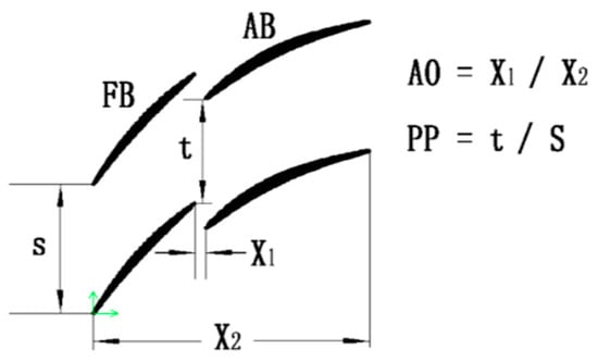
Figure 1.
Schematic of a tandem blade.
In this paper, numerical simulations were conducted on a double-stage transonic compressor with tandem blades and a 2D tandem blade model was derived from the 50% blade height of this compressor. The configuration of the compressor and the 2D tandem blade model in the meridional view is shown in Figure 2. The main design parameters, such as AO/PP, solidity ratio, and camber ratio, were modified during the primary design process. The numerical simulation solver was ANSYS 15.0, which uses an element-based finite volume method and an implicit discrete-in-time scheme based on Reynolds-averaged Navier–Stokes (RANS) equations, using a k-ε turbulence model; k is the turbulence kinetic energy, and ε is the turbulence eddy dissipation (the rate at which velocity fluctuations dissipate). The continuity and momentum equations are shown as Equations (1) and (2), where SM is the sum of body forces, ueff is the effective viscosity accounting for turbulence, and p’ is the modified pressure, as defined in Equation (3) [19,20]. The convergence of the simulation for the 2D tandem blade model is shown in Figure 3. The mass flow and momentum residuals decline by three orders of magnitude, and the inlet mass flow rate becomes stable in outlet value. Mesh independence and validation has been done in previous research to improve simulation accuracy [21].
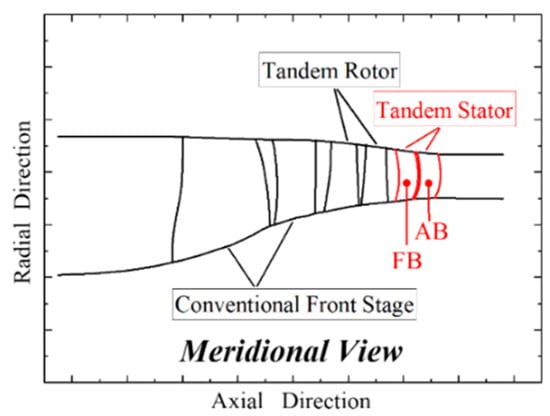
Figure 2.
Configuration of the double-stage compressor with tandem blades.
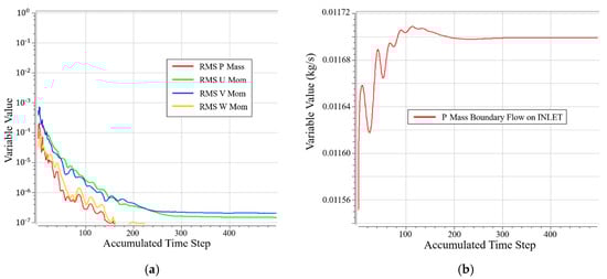
Figure 3.
Convergence of the simulation for the 2D tandem blade model; incidence = −1°, inlet Mach = 0.8. (a) Momentum and mass; (b) mass flow rate on INLET.
2.1. Setup for 2D Tandem Blade Model
The baseline 2D tandem blade design parameters are shown in Table 1. Considering the inflow Mach number of 0.8 at the DE (design) point, the CD airfoil was selected for both FB and AB. The camber line and thickness distributions are shown in Figure 4.

Table 1.
Tandem airfoil geometric parameters.
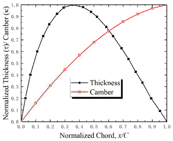
Figure 4.
Tandem blade camber line and thickness.
An HOH topology structured mesh was generated in blade-to-blade surface with the AutoGrid5 software package, as shown in Figure 5. The total grid number was about 195,000 (the number along the axial; circumferential and spanwise: 305 × 71 × 9), and there were 91 grids along the chord-wise of FB and AB. The first nondimensional wall distance was specified to ensure that y+ was less than 5, and the grid expansion ratio near the wall was kept at less than 1.2.
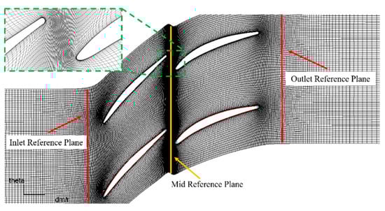
Figure 5.
2D Tandem blade model computation fluid dynamic (CFD) mesh.
The boundary conditions were obtained from the 50% blade height of the transonic tandem stator: at the DE point, the inlet Mach number was 0.8, and the Reynolds number based on the chord length was 1.86 × 10⁶.
Inlet boundary conditions: specify the total temperature—Tt11, total pressure—Pt11, three velocity directions (Vz ≡ 0, Vy/Vx = tanβ11).
Outlet boundary conditions: specify the mass flow rate.
It can be seen from the flow continuity in Equation (4), the inlet velocity directions and outlet mass flow rate should change correspondingly to ensure that the inlet Mach number remains at 0.8 under different incidence conditions.
2.2. Setup for Double-Stage Transonic Compressor with Tandem Blades
A 3D RANS simulation was conducted for a double-stage transonic compressor with tandem blades at 100%, 90%, and 80% design speeds. The baseline tandem stator design parameters are listed in Table 2. It should be noted that the optimization was conducted on the tandem stator only, while the inlet stage and the tandem rotor were kept fixed in this paper. The FB and AB airfoils of 15 blade elements along the radius were kept the same as the 2D model mentioned above.
Table 2.
Tandem stator design parameters.
The total grid number of the tandem stator was approximately 2.1 million (the number along the axial; circumferential and spanwise: 381 × 71 × 77). The first nondimensional wall distance was specified to ensure that y+ was less than 5, and the grid expansion ratio near the wall was kept at less than 1.2. The mesh topology and some other installations were the same as the 2D tandem case shown in Figure 6, so no additional explanation is needed.
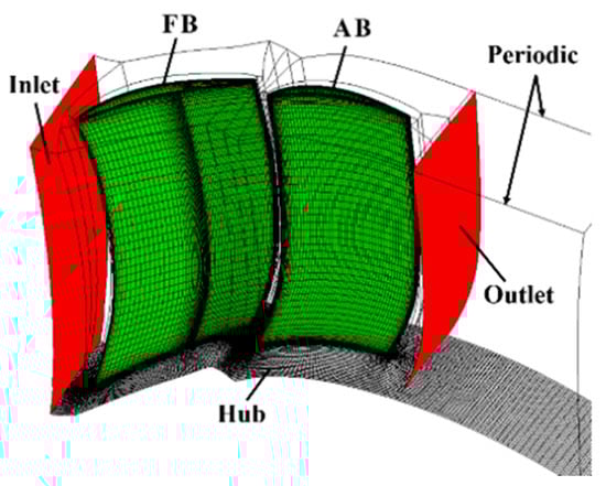
Figure 6.
Compressor with tandem blades CFD mesh.
Standard atmosphere conditions (Pt11 = 101325Pa, Tt11 = 288.15K, and axial flow direction) were imposed as the inlet reference plane. Additionally, outlet average static pressure was increased gradually to achieve the compressor characteristics in 100%, 90%, and 80% design speeds.
3. Analysis of the Aerodynamic Interaction between the Forward and Aft Blades
In this section, the investigation is focused on the fluid mechanisms of the aerodynamic interaction between FB and AB. To accomplish this objective, FB and AB were simulated in 2D single-blade and tandem-blade configurations, respectively. Based on the results, the difference in their behaviors in the two configurations was revealed. The fluid mechanism studies for FB and AB are individually expounded below.
3.1. The FB Flow Characteristic Influenced by AB
The baseline FB was simulated in single-blade and tandem configurations, and its behavior, influenced by the AB, was analyzed. Comparison of FB blade performance in two configurations is shown in Figure 7 (the reference plane was kept in the same position). The FB blade loss increases by approximately 8% in the tandem configuration. Nevertheless, the incidence range is almost the same, i.e., the incidence range of tandem blades is mainly decided by FB.
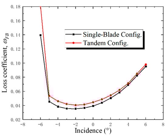
Figure 7.
Forward blade (FB) loss coefficients for single-blade and tandem configurations.
To further understand the reason that leads to the increase of blade loss in the tandem configuration, the comparison of isentropic Mach number distributions in three typical operating conditions is shown in Figure 8. The distributions in the single-blade configuration are similar to the CD airfoil. However, in the tandem configuration, the airflow decelerates near the PS trailing edge and the aerodynamic load increases near the FB PS trailing edge, which makes the isentropic Mach number distributions deviate from the ideal profile of CD airfoils. As shown in Figure 9, the stagnation effect of AB leads to a change in the static pressure field near the AB leading edge, and it can be regarded as an additional pressure field induced by AB. In the present relative position of FB and AB, the FB trailing edge is located in a high-pressure region caused by AB, which influences the FB isentropic Mach number distributions and causes a further increase of blade loss. It should be emphasized that static pressure changes rapidly near the AB leading edge; therefore, the effect of the additional pressure field is obviously influenced by FB and AB’s relative position. Hence, it is necessary to select a proper relative position before the elaborate optimization.
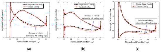
Figure 8.
Comparison of the FB isentropic Mach number in single-blade and tandem configurations. (a) Incidence = −5°; (b) incidence = −1°; (c) incidence = +5°.
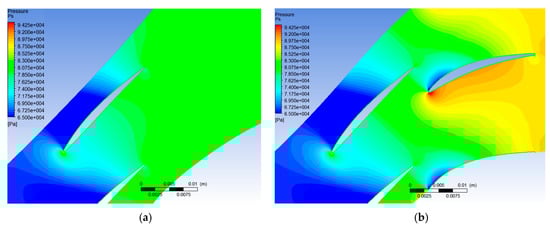
Figure 9.
Comparison of static pressure contours in single-blade and tandem configurations; incidence −1°, inflow Mach number 0.8. (a) FB single-blade configuration; (b) tandem configuration.
3.2. The AB Flow Characteristic Influenced by FB
The baseline AB was simulated in single-blade and tandem configurations, and its behavior, influenced by FB, was analyzed. It should be noted that the inlet boundary conditions of the AB single-blade configuration were extracted from the min-plane in the tandem configuration. The AB flow status in the tandem configuration can reappear in the single-blade simulation by using this method, except for the gap flow and the diffusion of the FB wake. The Mach number and airflow angle in mid-plane, corresponding to the FB incidence, are shown in Table 3.
Table 3.
The aft blade (AB) inlet conditions.
Compared to the single-blade configuration, the AB isentropic Mach number distributions in Figure 10 reveal two significant characteristics in the tandem configuration. Firstly, the acceleration of the gap flow in the tandem blade induces a low-pressure region near the leading edge of the AB SS, which leads to a tendency for an increase of AB local incidence (Figure 11). Secondly, the FB wake blocks up the AB passage, especially for a large positive-incidence condition, which will change the aerodynamic load and diffusion process of AB. The AB isentropic Mach number increased to about 0.1 in the tandem configuration. In addition, as shown in Figure 12 and Figure 13, the local aerodynamic load near the AB trailing edge decreases due to the blockage effect of the FB wake; consequently, the separation near the AB suction side is restrained.
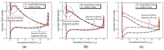
Figure 10.
Comparison of the AB isentropic Mach number in single-blade and tandem configurations. (a) Incidence = −5°; (b) incidence = −1°; (c) incidence = +5°.
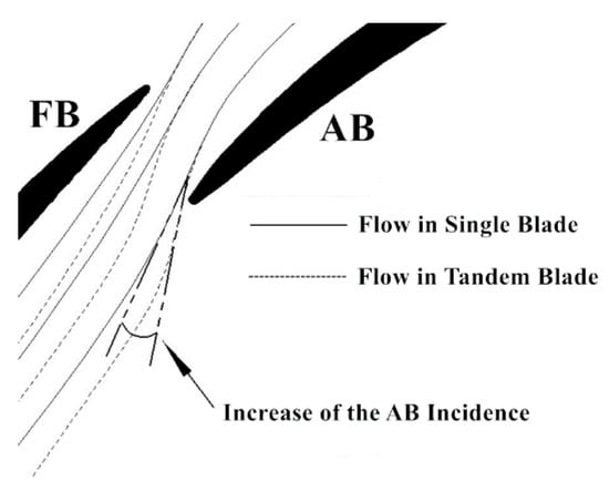
Figure 11.
Tandem blade gap flow detail.
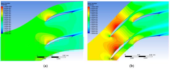
Figure 12.
Comparison of Mach contours in single-blade and tandem configurations. FB incidence −1°; FB inflow Mach number 0.8. (a) AB single-blade configuration; (b) tandem configuration.
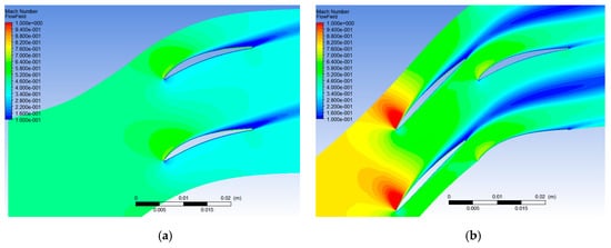
Figure 13.
Comparison of Mach contours in single-blade and tandem configurations. FB incidence +5°; FB inflow Mach number 0.8. (a) AB single-blade configuration; (b) tandem configuration.
4. Optimization for Tandem Blades
In this section, the “camber line modification method” was put forward to fully utilize the gap flow in subsonic tandem blades. Furthermore, this method was verified by carrying out the optimizations for both the 2D tandem blade model and a double-stage transonic compressor with tandem blades. In the following optimization results, we are concerned with two issues: (1) the flow mechanism of the camber line modification method’s influence on the blade element; (2) feasibility and validity of this method used in the optimization of 2D tandem blades and even compressors with tandem blades.
4.1. Optimization for a 2D Tandem Blade Model
4.1.1. The Optimization Procedure
The simulation results for a baseline 2D tandem blade indicate that the typical CD airfoil achieved acceptable overall performance. However, some potential, improving directions are still being reflected in the comparison of isentropic Mach number distributions in single-blade and tandem configurations. It should be noted that the design parameters, such as AO/PP, solidity ratio, and camber ratio, were selected during a proper interval in the preliminary design, and they are kept fixed during the optimizing process. The camber line and blade angle were modified to adapt to aerodynamic interaction better in tandem blades, with the objective of reducing total pressure loss while maintaining the aerodynamic load. Based on proper preliminary design parameters and the CD airfoil, the modification process for tandem blades and the critical aerodynamic criteria can be summarized in Figure 14. The modification concepts for FB and AB will be discussed in the following parts, respectively.
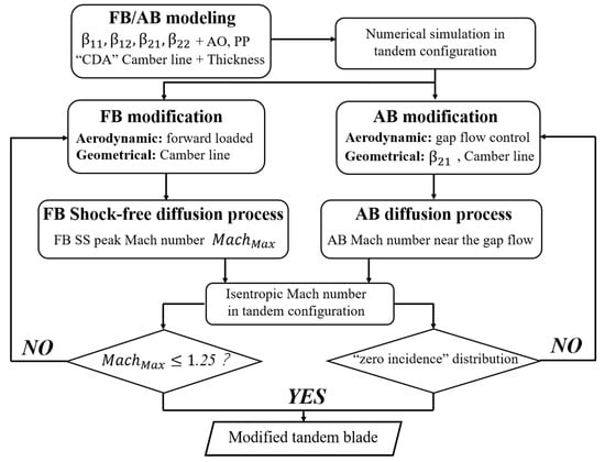
Figure 14.
Modification process for tandem blades based on a CD airfoil.
- Modification for the forward blade
As mentioned in the previous analysis, the FB diffusion process is influenced by the AB pressure field in the tandem configuration, as characterized by the increase of the aerodynamic load near the FB trailing edge. To better adapt to the aerodynamic interaction, a negative camber is adopted near the FB trailing edge, which leads to a reduction in the local aerodynamic load. Normalized camber line distributions of the modification blade are shown in Figure 15; the normalized camber increases in correspondence with the normalized chord length, varying from 0 to 0.5. Additionally, a negative camber line is used from 0.7 to 1.0 normalized chord length.
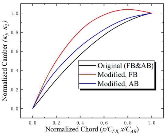
Figure 15.
Comparison of camber line between baseline and modified blades.
- Modification for the aft blade
Due to AB being located in the rear of FB, the impact of gap flow is more significant. Additionally, the aerodynamic interaction should not be ignored during the modification process. Firstly, to make the AB incidence adapt to the influence of gap flow, the modified AB inlet metal angle decreases by 5°. The criterion of “AB incidence modification” can be estimated by the AB surface isentropic Mach number; that is, AB should form a “zero incidence” distribution in the tandem configuration. Secondly, to ensure a stronger converging passage between FB and AB, the normalized camber increases more rapidly before 30 percent of the chord length, which is beneficial for preventing the separation near the AB trailing edge. A comparison of baseline and modified blade geometry is shown in Figure 16.
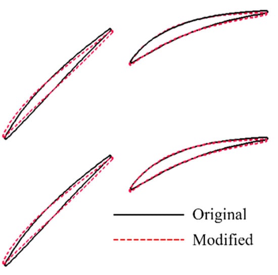
Figure 16.
Comparison of blade geometry.
4.1.2. Numerical Simulation Results and Analyses
Figure 17 presents the comparisons of tandem blade performances (incidence—total pressure loss and incidence—diffusion factor characteristics) between the baseline and optimized blades, with an inflow Mach number of 0.8. The total pressure loss at the DE point decreases by about 6%, and the incidence range extends 2° while maintaining the aerodynamic load.
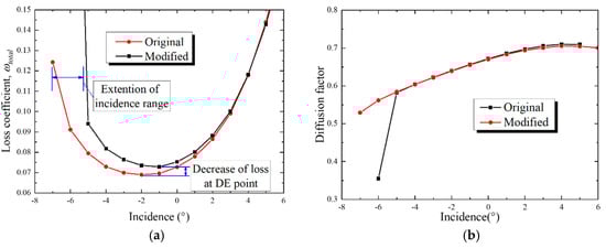
Figure 17.
Comparison of baseline and optimized blade performances. (a) Incidence—loss coefficient; (b) incidence—diffusion factor.
The performance improvement under large negative-incidence conditions illustrates the growth in flow capacity due to the well-designed FB camber line. Consequently, there is an obvious shock wave passing through the baseline FB passage (Figure 18a), which shows that it is operating in a deep choke status with an incidence of −5°, while the optimized blade is still operating in an ideal status with the same incidence condition (Figure 19a). Compared with the baseline, the optimized blade has a slightly increased AB suction spike, especially for −5° and 0° incidence conditions, and it provides stronger dynamic pressure to prevent the separation near the AB trailing edge.
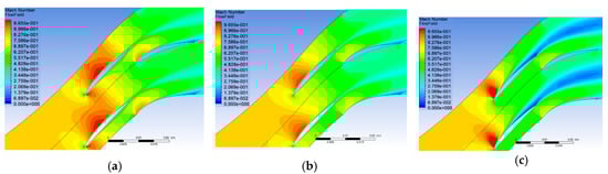
Figure 18.
Baseline blade Mach contours in typical operating conditions. (a) i = −5°; (b) i = −1°; (c) i = +5°.
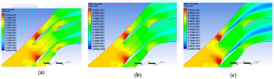
Figure 19.
Optimized blade Mach contours in typical operating conditions. (a) i = −5°; (b) i = −1°; (c) i = +5°.
As shown in Figure 20, the isentropic Mach number distributions reveal that the optimized blade achieves a typical CD airfoil shape in three operating conditions.
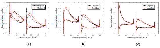
Figure 20.
Comparison of the baseline and optimized blade surface isentropic Mach numbers. (a) i = −5°; (b) i = −1°; (c) i = +5°.
According to the FB distributions at the DE point, there are more radical accelerations before the 0.1 normalized chord length, and there is a subsequent continuous deceleration on the suction side, while flow velocity is kept nearly constant on the pressure side. The overall FB load distribution moves forward; consequently, the suction spike Mach number increases from 1.0 to 1.05 at the DE point, which is still well within the acceptable range. We emphasize that the FB forward-load should be carefully controlled to avoid a strong normal shock on the suction side, especially when the inflow Mach number is higher than 0.8.
On the other hand, the most significant difference in AB is the modification of local incidence conditions compared to the baseline. Although FB incidences change in a wide range, the optimized AB has a typical distribution of a CD airfoil near the 0° incidence condition. The modification for AB incidences is good for reducing total pressure loss under the whole operating conditions.
4.2. Optimization for a Double-Stage Transonic Compressor with Tandem Blades
To further assess the availability of the “camber line modification method”, a double-stage transonic compressor, with tandem blades at the rear stage, was optimized and simulated at 90% and 80% design speeds.
4.2.1. The Optimization Procedure
As is known to compressor designers, the challenge of a multistage compressor at low speeds is that the rear stages cannot pass through enough mass flow to prevent the front stages from stalling [22]. Since the tandem stator is located at the rear stage, a tandem airfoil with a wider incidence range is of great importance for the matching characteristic of the double-stage transonic compressor at low speeds. Based on the above analysis, the following two challenges are explained for further understanding of the tandem stator optimization in this paper. Firstly, the radial distribution of tandem stator incidence at design speed and off design speed are presented in Figure 21a, which determines the essential incidence range from hub to tip, varying from 6° to 10° correspondingly. That is, a nonoptimized tandem stator with a smaller incidence range may lead to double-stage compressor performance deterioration (difficulty in stage-matching at low speeds or an early corner stall before the rotor achieves its maximum pressure rise at design speed). Secondly, as shown in Figure 21b, the inflow Mach number, along the spanwise, varies from 0.95 to 0.8 at design speed. The shock wave in FB seems inevitable with such a high inflow Mach number; consequently, the optimization using the camber line modification method should be finely balanced on blade loss and incidence range.
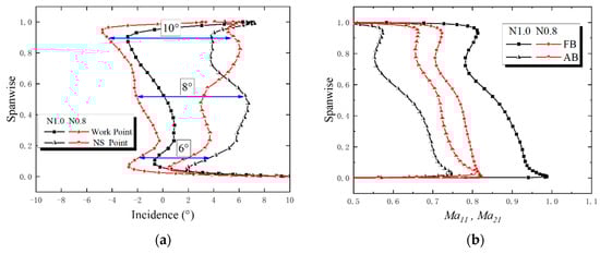
Figure 21.
Operating conditions of the tandem stator at design speed and off design speed. (a) Incidence range; (b) inlet Mach number.
Base on the above analysis, the rear stage tandem stator of a double-stage compressor was optimized (15 blade elements along the spanwise), while the other blade rows were kept fixed. The optimization principles and the method are the same as the 2D tandem blade model, so no additional explanation is needed here.
4.2.2. Numerical Simulation Results and Analyses
The comparisons of baseline and optimized compressor characteristics, normalized by the results at the DE point, are shown in Figure 22. The effect of tandem stator optimization on pressure rise and efficiency is negligible at design speed. However, the compressor characteristic is obviously modified at 80% design speed: the efficiency increases approximately 2 points at the CO (cooperating) point, with an overall improvement along the equal engine speed line. Additionally, mass flow rises nearly 1.6% at the choke point. The characteristics of the front and rear stages at 80% design speed are shown in Figure 23; both the efficiency and mass flow of each stage increase significantly in the whole operating conditions. Note that compressor performance improvement benefits from the modification of the tandem stator only, which indicates that the flow capacity enhancement of the tandem stator has a great impact on the matching characteristic of the double-stage transonic compressor at low speeds.
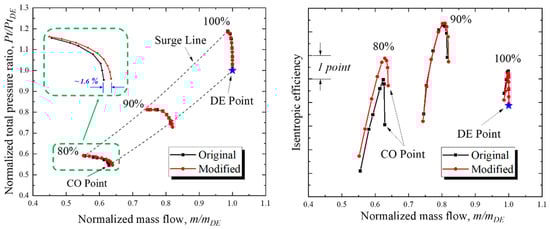
Figure 22.
Characteristics of a double-stage compressor.
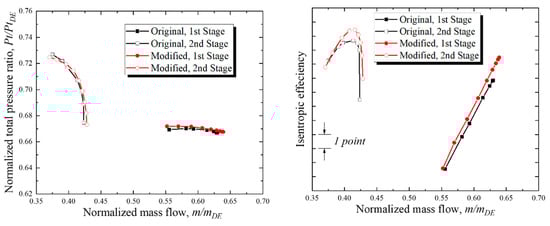
Figure 23.
Characteristics of front and rear stages, 80% design speed.
- Discussions for Flow Details At 80% Design Speed, CO Point
The CO points of baseline and optimized compressors at 80% design speed are marked in their respective characteristic maps. As shown in Figure 24, the FB isentropic Mach number distributions at 10%, 50%, and 90% blade heights illustrate obviously different flow status in the two tandem stators: the Mach number decreases about 0.1, and the location of passage shock moves forward for the 10% chord length. The phenomena stated above indicate that the rear stage tandem stator operates away from the deep choke condition at the CO point. A similar tendency can be reflected in the Mach contours near the blade surface, as shown in Figure 25. Compared to the baseline tandem stator, the optimized scheme has a weaker and forward-moving passage shock and, as a consequence, a smaller separation zone induced by shock-boundary layer interaction.
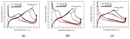
Figure 24.
FB surface isentropic Mach number at 80% design speed at the CO point. (a) 10% blade height; (b) 50% blade height; (c) 90% blade height.
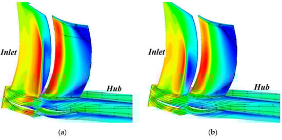
Figure 25.
Mach contours near the blade surface at 80% design speed at the CO point. (a) Original; (b) modified.
- Discussions for flow details at design speed, DE point
As stated above, the inlet Mach number along the spanwise varies from 0.95 to 0.8 at design speed, so the shock wave near the FB SS should be controled to avoid a rapid increase of loss. The FB isentropic Mach numbers at the DE point are shown in Figure 26; due to the forward-load of FB, the suction spike Mach number increases from 1.0 to 1.05 at the hub and mid-span and the location moves forward for the 5% chord length. The Mach contours near the blade surface show that the FB SS normal shock enhances slightly (Figure 27). Nevertheless, the tandem stator is still operating at good status.
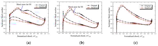
Figure 26.
FB surface isentropic Mach number at 100% design speed at the DE point. (a) 10% blade height; (b) 50% blade height; (c) 90% blade height.
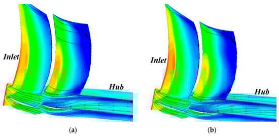
Figure 27.
Mach contours near the blade surface at 100% design speed at the DE point. (a) Original; (b) modified.
5. Conclusions
Based on the analysis of the aerodynamic interaction of tandem blades, a new optimization method for a subsonic tandem blade is put forward; the effectiveness and feasibility of the method are validated using a 2D tandem blade model and a double-stage compressor with tandem blades. The main conclusions are as follows:
- (1)
- Under subsonic (shock-free) conditions, the traces of aerodynamic interaction between FB and AB can be reflected in blade surface isentropic Mach number distributions. Compared to the single-blade configuration, the FB trailing edge local aerodynamic load and the AB incidence increased under the FB and AB relative position investigated in this paper (AO ~ −0.1, PP ~ 0.7). Furthermore, this phenomenon will lead to additional total pressure loss in the tandem configuration.
- (2)
- To fully utilize the aerodynamic interaction in tandem blades, the optimization principles and the “camber line modification method” are presented in this paper: in a tandem configuration, the FB and AB surface isentropic Mach number distributions (i.e., the local aerodynamic load) can be revised to rapidly and conveniently approach the CD airfoil by using this method.
- (3)
- To validate the effectiveness and feasibility of this method, two tandem blade optimization examples were performed and simulated:
- Optimization for a 2D tandem blade model: with an inflow Mach number of 0.8, the minimum loss decreases by 6%, and the incidence range extends approximately 2° compared to the baseline;
- Optimization for a double-stage transonic compressor with tandem blades: at 80% design speed, isentropic efficiency increases by 2 points, with an increase of mass flow by 1.6% at the choke point simultaneously. In addition, compressor characteristics at design speed remain almost unchanged.
Author Contributions
Conceptualization, B.L. and X.Y.; methodology, Y.T.; software, Y.T.; validation, Y.T.; formal analysis, Y.T.; investigation, Y.T.; data curation, Y.T.; writing—original draft preparation, Y.T.; writing—review and editing, Y.T.; project administration, Y.T.; funding acquisition, Y.T. All authors have read and agreed to the published version of the manuscript.
Funding
This research was funded by the “Fundamental Research Funds for the Central Universities”, grant number 3122018C009.
Acknowledgments
The authors would like to acknowledge David’s help in improving the grammar of the manuscript.
Conflicts of Interest
The authors declare no conflict of interest.
Abbreviations
| FB | Forward blade |
| AB | Aft blade |
| LE | Leading edge |
| TE | Trailing edge |
| DE point | Design point |
| NS point | Near stall point |
| CO point | Cooperating point |
| S | Pitch |
| C | Chord |
| t | Pitch space between FB TE and AB LE |
| Ma | Mach number |
| Subscripts | |
| 11 | Station for the forward blade inlet |
| 12 | Station for the forward blade outlet |
| 21 | Station for the aft blade inlet |
| 22 | Station for the aft blade outlet |
| Symbols | |
| x | Axial direction |
| y | Circumferential direction |
| z | Radial direction |
| V | Air flow velocity |
| χ | Blade metal angle (measured from axial direction, °) |
| τ | Blade normalized thickness, τLocal/τMax |
| κ1 | Forward blade normalized camber, (χ11 − χ)/(χ11 − χ12) |
| κ2 | Aft blade normalized camber, (χ21 − χ)/(χ21 − χ22) |
| m | Mass flow rate (kg/s) |
| Pt | Total pressure (Pa) |
| Ps | Static pressure (Pa) |
| Tt | Total temperature (K) |
| β | Flow angle to the axial direction (°) |
| A | Area (m2) |
| ωTotal | Tandem blade total pressure loss, |
| ωFB | Forward blade total pressure loss, |
| i | Incidence, β – χ11 (°) |
References
- Sulam, D.H.; Keenan, M.J.; Flynn, J.T. Single-Stage Experimental Evaluation of Highly-Loaded High-Mach-Number Compressor Stages Part 2: Data and Performance Multiple-Circular-Arc Rotor. July 1972. Available online: https://core.ac.uk/download/pdf/80656364.pdf (accessed on 20 June 2018).
- Brent, J.A.; Clemmons, D.R. Single-Stage Experimental Evaluation of Tandem-Airfoil Rotor and Stator Blading for Compressors Part 8; NASA Center for Aerospace Information: Hanover, MD, USA, 1974; NASA-CR-134713. [Google Scholar]
- Bammert, K.; Beelte, H. Investigation of an axial flow compressor with tandem cascade. J. Eng. Power 1980, 102, 971. [Google Scholar] [CrossRef]
- Bammert, K.; Staude, R. Optimization for Rotor Blades of Tandem Design for Axial Flow Compressors. J. Eng. Power 1980, 102, 369. [Google Scholar] [CrossRef]
- Smith, A. High-Lift Aerodynamics. J. Aircr. 1975, 12, 501–530. [Google Scholar] [CrossRef]
- Nezym, V.Y.; Polupan, G.P. A New Statistical-Based Correlation for the Compressor Tandem Cascade Parameters Effects on the Loss Coefficient. In Proceedings of the ASME Turbo Expo, Montreal, QC, Canada, 14–17 May 2007. GT2007-27245. [Google Scholar]
- McGlumphy, J.; Ng, W.-F. Numerical Investigation of Tandem Airfoils for Subsonic Axial-flow Compressor Blades. J. Turbomach. 2009, 131, 021018. [Google Scholar] [CrossRef]
- McGlumphy, J.; Ng, W.F. 3D numerical investigation of tandem airfoils for a core compressor rotor. In Proceedings of the ASME Turbo Expo, Berlin, Germany, 9–13 June 2008. GT-2008-50427. [Google Scholar]
- Liu, B.; Fu, D. Development of a Preliminary Design Method for Subsonic Splittered Blades in Highly Loaded Axial-Flow Compressors. Appl. Sci. 2017, 7, 283. [Google Scholar] [CrossRef]
- Schlaps, R.C.; Shahpar, S. Automatic Three-Dimensional Optimization of a Modern Tandem Compressor Vane. In Proceedings of the ASME Turbo Expo, Düsseldorf, Germany, 16–20 June 2014. GT2014-26762. [Google Scholar]
- Schneider, T.; Kozulivic, D. Flow Characteristics of Axial Compressor Tandem Cascades at Large Off-design Incidence Angles. In Proceedings of the ASME Turbo Expo, San Antonio, TX, USA, 3–7 June 2013. GT2013-94708. [Google Scholar]
- Kumar, A.; Pradeep, A.M. Performance Evaluation of a Tandem Rotor under Design and Off-design Operation. In Proceedings of the ASME Turbo Expo, Oslo, Norway, 11–15 June 2018. GT2018-75478. [Google Scholar]
- Kumar, A. Design and off-design behavior of a tandem rotor stage. Inst. Mech. Eng. Part G-J. Aerosp. Eng. 2020, 234, 927–942. [Google Scholar] [CrossRef]
- Liu, H.; Yue, S. Unsteady Study on the Effects of Matching Characteristic of Tandem Cascade on the Performance and Flow at Large Angle of Attack. J. Therm. Sci. 2018, 27, 505–515. [Google Scholar] [CrossRef]
- Ju, Y.; Zhang, C. Multi-objective Optimization Design Method for Tandem Compressor Cascade at Design and off Design Condition. In Proceedings of the ASME Turbo Expo, Glasgow, UK, 14–18 June 2010. GT2010-22655. [Google Scholar]
- Hergt, A.; Siller, U. About Transonic Compressor Tandem Design—A Principle Study. In Proceedings of the ASME Turbo Expo, Montréal, QC, Canada, 15–19 June 2015. GT2015-42115. [Google Scholar]
- Hoeger, M.; Baier, R.-D. High Turning Compressor Tandem Cascade for High Subsonic Flows, Part1: Aerodynamic Design. In Proceedings of the 47th AIAA/ASME/SAE/ASEE Joint Propulsion Conference & Exhibit, San Diego, CA, USA, 31 July–3 August 2011. AIAA2011-5602. [Google Scholar]
- Hoeger, M.; Baier, R.-D. High Turning Compressor Tandem Cascade for High Subsonic Flows, Part2: Numerical and Experimental Investigations. In Proceedings of the 47th AIAA/ASME/SAE/ASEE Joint Propulsion Conference & Exhibit, San Diego, CA, USA, 31 July–3 August 2011. AIAA2011-5602. [Google Scholar]
- Marta, S.; Marek, J. Multiphase model of flow and separation phases in a whirlpool: Advanced simulation and phenomena visualization approach. J. Food Eng. 2020, 274, 109846. [Google Scholar]
- Ansys Cfx Help, 15th ed.; ANSYS Inc.: Canonsburg, PA, USA, 2015.
- Tao, Y.; Wu, Y.; Yu, X.; Liu, B. Analysis of Flow Characteristic of Transonic Tandem Rotor Airfoil and Its Optimization. Appl. Sci. 2020, 10, 5569. [Google Scholar] [CrossRef]
- Cumpsty, N.A. Compressor Aerodynamics, 2nd ed.; Krieger Publishing Company: Malabar, FL, USA, 2004. [Google Scholar]


Publisher’s Note: MDPI stays neutral with regard to jurisdictional claims in published maps and institutional affiliations. |
© 2020 by the authors. Licensee MDPI, Basel, Switzerland. This article is an open access article distributed under the terms and conditions of the Creative Commons Attribution (CC BY) license (http://creativecommons.org/licenses/by/4.0/).