1. Introduction
Modular construction is the process where projects consist of individual sections, prefabricated in an off-site controlled manufacturing facility, and assembled at the construction site. This method can overcome the influence of factors such as poor construction site environment on the project quality. The quality control of modular construction is mainly carried out from three aspects: preconstruction stage, production stage, and installation construction [
1]. Modular construction effectively improves the efficiency and quality of both design and construction. Also, it shortens the duration and cost of construction projects, which represents an important trend in the development of architectural industrialization [
2,
3,
4]. A floodwall is a primarily vertical artificial barrier that is erected along the banks of a stream or path of floodwaters to prevent floodwaters from reaching the area behind the structure during seasonal or extreme weather events. Traditional floodwalls are mainly constructed from concrete and metal elements. This system requires a large land area, which may restrict access to the structure. It can be costly for construction and maintenance. Also, the traditional floodwalls may block the natural view and damage the landscape along the river. Hence, a removable floodwall system is designed and introduced to overcome those challenges brought by the traditional floodwalls. Unlike traditional ones, these structures are movable and can be deployed or erected only in flooding times. Removable floodwall systems can be applied to individual buildings, smaller areas, or a large scale of the infrastructure such as dams, large-size port piers, railway tunnel portals, culvert openings of expressways, openings of civil air defense structures, and urban large-scale communities to prevent flood disasters [
5]. Compared with traditional flood protection methods, the removable floodwall takes advantage of the low labor intensity, high work efficiency, and small seepage [
6]. Also, a removable floodwall gives protection in case of flooding and open access to the floodplain over the remaining time. It can also be used as an emergency tool against flooding in unprotected low-lying areas in addition to the heightening of permanent flood protection structures in extreme events.
The installation processes of removable floodwalls typically consist of two permanent installed components (end posts, anchor plates) and four removable components (logs, ground seal, pressing tool, center post). Reinforced concrete plinths embedded with anchor plates are constructed in advance at the site of floodwalls. The center posts are bolted onto the stationary anchor plates. The logs are then compressed vertically with the pressing tools to provide a high level of leak tightness. The logs will get compacted among themselves because of their intermediate seals. Additionally, the lowest log with its special ground seal creates a water-tight seal with the ground. After the flood recedes, all components are reversely removed and orderly stored in a warehouse.
One of the critical installation procedures is the accuracy tolerance control of anchor plates, embedded in reinforced concrete plinths for connecting fixed columns. Ensuring the installation precision of anchor plates without deviation during concrete pouring is crucial because the control precision of concrete pouring is in millimeter accuracy. However, the current methods for analyzing anchor plates’ tolerance accuracy rely primarily on manual inspections and contact type measurements, such as rulers and measurement tapes, which are time-consuming and costly. Also, there is a lack of systematic storage and management of the information obtained.
A significant portion of the researchers and practitioners adopt non-contact sensing techniques to monitor the dimensional properties of the precast structures. Laser scanners have recently been one of the most popular measurement tools in the construction industry [
7]. Laser scanning directly acquires three-dimensional (3D) point cloud data at a high accuracy level, with 2 to 6 mm at 50 m [
8,
9]. According to the existing studies [
10,
11,
12], which conducted comparisons between laser scanning methods and vision-based approaches, the laser scanning approaches offer better accuracy than vision-based methods.
Building information modeling (BIM) combined with prefabricated modular components has enabled integrated construction and engineering workflows on quality control. Using BIM to coordinate, document, and control the quality in modular constructions appears to be a practical approach [
13]. However, the previous research focused on the quality control of production processes [
14] and modular components [
7]. There is a research gap on how to control the quality in the install stage of modular construction with the integrated method of BIM and laser scanning.
This paper introduces a framework that integrates the use of BIM and 3D laser scanning technology to enable rapid analysis of the assemble quality of anchor plates and other components for a removable floodwall. The researchers first conducted a thorough literature review of laser scanning and BIM in modular construction quality control. Then, this study proposes a framework of the modular floodwall installation and quality control process. The following sections describe the data capture, quality inspection procedure, and the data storage and delivery methods accordingly. The study utilizes the data of a real project located in a riverside city in China for validating the level of technical feasibility and accuracy of the presented methods. The results indicate that the proposed integration of BIM and 3D laser scanning can produce a rapid and reliable method to proactively control the assemble quality of anchor plates for removable floodwall during field installations.
2. Literature Review
2.1. BIM for Construction Quality Control
BIM is more than a new tool for the construction industry [
15]. It proposed a relatively new and collaborative environment in which the project team can work. It is a process that is supported by various tools and technologies. For example, BIM-authoring tools which are used to develop a building information model include Autodesk Revit, SCIA (a 3D structural engineering software), ARCHICAD (an architectural BIM CAD software), Tekla Structures, etc. BIM analysis tools which are used to perform structural analysis and energy calculations include SAP2000 (a structural software for analysis and design), SCIA, AX3000 (a software for building services engineering, energy engineering and virtual reality solutions), etc. Many standards and protocols, for example, the Industry Foundation Classes (IFC), the BIM Collaboration Format (BCF), etc., are established to support the BIM industry. It has several dimensions, such as cost, time, quality, and safety, which enable a construction project to be executed with higher performance. In recent years, more and more researchers have applied BIM technology to construction quality control [
16,
17,
18]. The information mapping from BIM can improve the project’s progress monitoring, detailed planning, and management of material flows across the construction supply chain [
14]. Čuš-Babič et al. [
19] believed that BIM technology could effectively eliminate the information barriers between architectural design, prefabrication, and construction.
The BIM is a rich and formal model that provides an ample number of possibilities for automated quality inspections: it can interpret and execute various criteria ranging from client requirements to health codes, safety codes, and building design and construction regulations [
16]. The quality inspection process generally includes various phases according to the objectives and scope of a specific project. In general, the process includes four phases: rule interpretation, BIM model preparation, rule execution, and rule-checking reporting.
There are three types of BIM-based quality control methods [
17]: (1) physical quality control, (2) logical quality control, and (3) data quality control. Physical quality control includes elements’ checking and clash checking between physical elements on different construction specialties such as mechanical, electrical, and plumbing (MEP), and structure. Logical quality control relies on rule-based checking using formulas, architecture acts, guidelines, and specifications. Data quality control refers to data reliability checking. It checks whether a specific component has its proper attributes or not [
16].
Construction quality controlling during the design phase can improve design quality by detecting errors and omissions of design output. Quality checking in the construction phase can improve the feasibility of a building’s construction by detecting conflicts between various building elements or systems [
16]. Thus, the importance of BIM-based quality checking allows for quick decision-making and improves the design and quality of construction in building projects. Zhang et al. [
18] developed an automated error detection module and an installation system (i.e., fall protection installations such as staircases, slab edges, slab openings, and protective equipment) operated through BIM-authoring software Tekla Structures.
One of the important approaches of the BIM-based quality control is to compare the physical structure and built environment to the BIM model. Laser scanning technology provides a quick and efficient way to collect data.
2.2. Laser Scanning for Construction Quality Control
Laser Scanning is a novel surveying technology. A laser scanner sweeps the surrounding space with laser light to acquire 3D data points. A laser scanner emits a pulse of light, which measures the amount of time it takes to travel from the scanner to the object and back, allowing the scanner to calculate the distance. Point clouds provided by laser scanners can be used directly for measurement and visualization [
20]. One of the critical applications of laser scanning is construction quality control [
21,
22,
23]. Akinci et al. [
21] proposed a first formalization for integrating project 3D models and sensor systems to defect detection and characterization for construction quality control. Bosché and Guenet [
20] then presented the implementation of such a system, called the Scan-vs-BIM principle. This enables the system to automatically match 3D data points to each BIM model object.
Point cloud data that capture facilities’ existing conditions are adopted for the quality inspection of buildings and civil infrastructures. According to the different types of geometry quality, research efforts on geometry quality inspection can be divided into three categories, namely (1) dimensional quality inspection, (2) surface quality inspection, and (3) displacement inspection [
24]. The dimensional quality inspection has covered dimensions of prefabricated elements and dimensions of building façade elements, such as size [
25,
26], shape [
27], position [
28], and orientation [
28]. For surface quality inspection, most research works are focused on surface crack, spalling, flatness, and deformation/distortion. For surface cracks and spalling, local geometric features are commonly used to detect the target problems, such as the local curvatures [
29] or normal vectors [
30]. Displacement inspection is focused on the change of relative position of a structure or elements.
These research target problems include displacement of highway retaining walls [
31], displacement of dams [
32], deflection of bridges [
33], and displacement of landslides [
34]. These research works often need to collect point cloud data to monitor the displacement of structures by comparing point cloud data captured at different construction processes [
25]. In the fabrication phase, the components such as precast concrete elements or prefabricated pipe spools are inspected to ensure smooth installation and assembly on-site [
35].
Laser scanning can contribute to reconstructing the structure or components of a construction project. It can be integrated with BIM technology to ensure smooth control of the construction quality.
2.3. Integrated BIM and Laser Scanning for Construction Quality Control
The integration of 3D laser scanning and BIM offers an opportunity for construction quality control [
36]. Construction works on-site need to be assessed to ensure the as-built construction outcomes are consistent with the as-designed BIM model. Moreover, the discrepancy should be checked if it is less than the tolerance value [
24].
This quality control inspection always includes building façade elements, steel columns, floor slabs’ surface quality, displacement of highway retaining wall, and many others [
24]. Most of the inspections are conducted after the construction works are finished and during the construction process [
31]. Wang et al. [
37] developed a prototype of a real-time construction quality control system. The system can automatically collect on-site quality data, compare as-built point cloud data and an as-planned BIM model, and assess construction quality.
Tang and Akinci [
38] utilized laser scanners to collect dense 3D point clouds for bridge inspectors. Akinci et al. [
21] utilized sensing technologies and project modeling capabilities to develop an active quality control system, which included acquiring and updating detailed design information, identifying inspection goals, inspection planning, as-built data acquisition and analysis, and defect detection and management. Bosché [
28] introduced an approach for automated recognition of project 3D BIM objects in large laser scans to automatically control the compliance of projects to corresponding dimensional tolerances.
In general, the value of BIM models towards quality inspection and control is at two levels. The first level is integrating product specifications within the BIM model, which enables reliable and efficient data management throughout a project life cycle. The second level is a more robust construction quality inspection supported by updated and completed information [
20].
Some other advanced automation and robotics technologies were also used in construction management, which would enhance the quality control of modular construction projects. Sun et al. [
39] introduced the applications of the unmanned aerial vehicle (UAV) from urban planning, illegal construction supervision, environmental engineering management, waste management, intelligent transportation, and other aspects. Many companies use UAV on construction sites, with the majority of applications replacing traditional still photo and video acquisition. In addition to traditional uses of photographic information, photogrammetry software is being used to integrate this data into building information models for construction management [
40]. Irizarry and Costa [
41] developed a visual assets database from UAV-based images and videos collected during UAV flights at jobsites. The results revealed potential applications of UAV mainly for project progress monitoring, job site logistics, evaluating safety conditions, and quality inspections, among other secondary management tasks. Dai et al. [
42] discussed the photogrammetric in modeling and surveying for construction quantity takeoff, quality control, and site safety monitoring applications. Lee and Park [
43] used 3D stereo vision to track the location of multiple on-site workers, and their method provides good reference for this study.
In summary, BIM and 3D laser scanning began to be gradually applied in the construction of quality inspection and control, especially the quality control of modular construction. However, most of them are focused on the construction process and the module production process. The research of the modular building installation process and embedded components’ installation quality control are still relatively few. This study plans to develop a quality tolerance control system with the integrated BIM and 3D laser scanning based on the modular structure installation processes, and use the removable flood wall project as an example to confirm the feasibility of the method.
3. Methodology
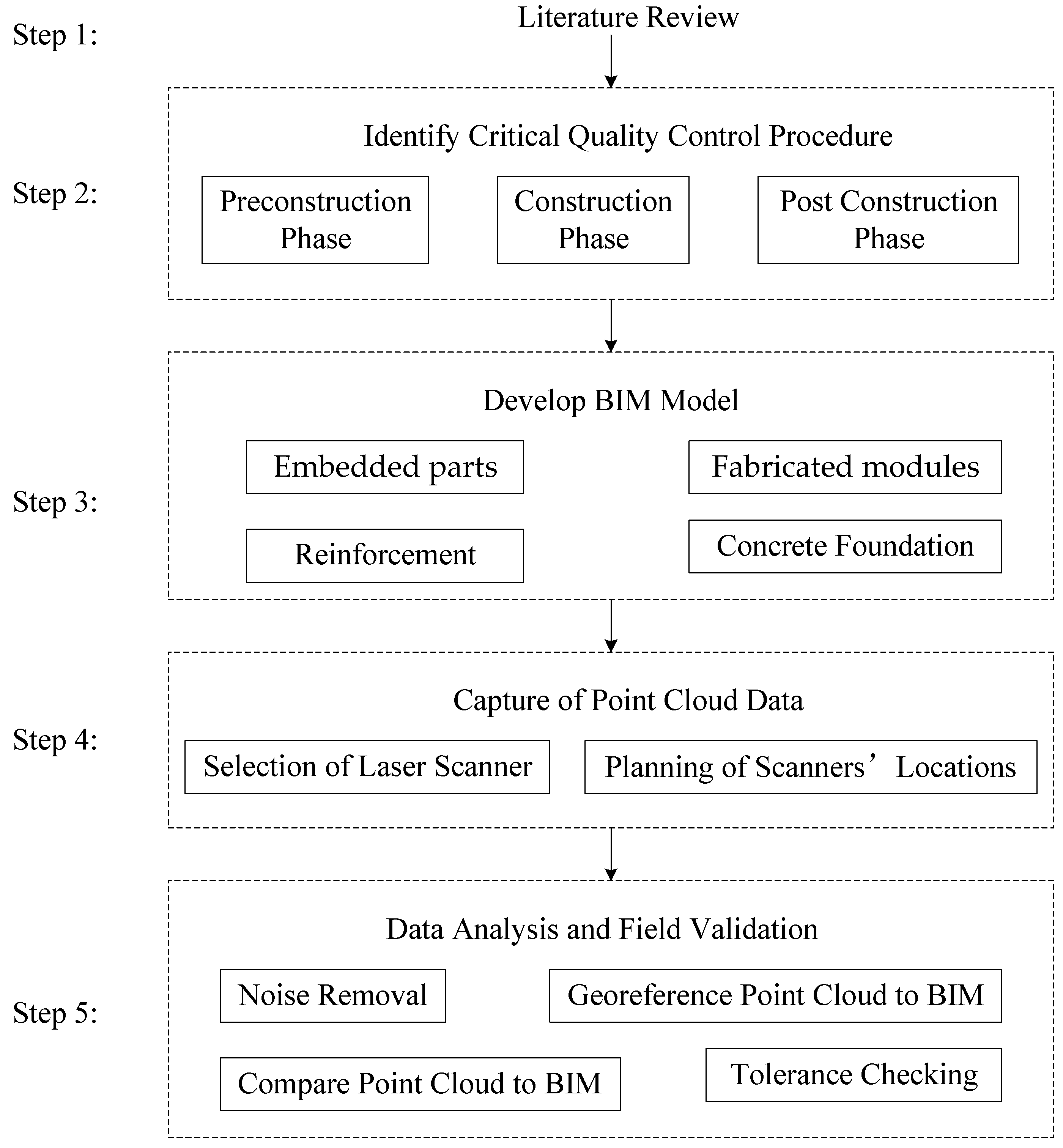
This section presents a methodology of using 3D laser scanning and BIM technology for quality tolerance control on a modular construction project. A research framework was developed, as shown in
Figure 1.
Step 1: Literature review. This study first conducted a thorough literature review and background study to evaluate the feasibility of using 3D laser scanning and BIM for modular construction quality control and tolerance analysis.
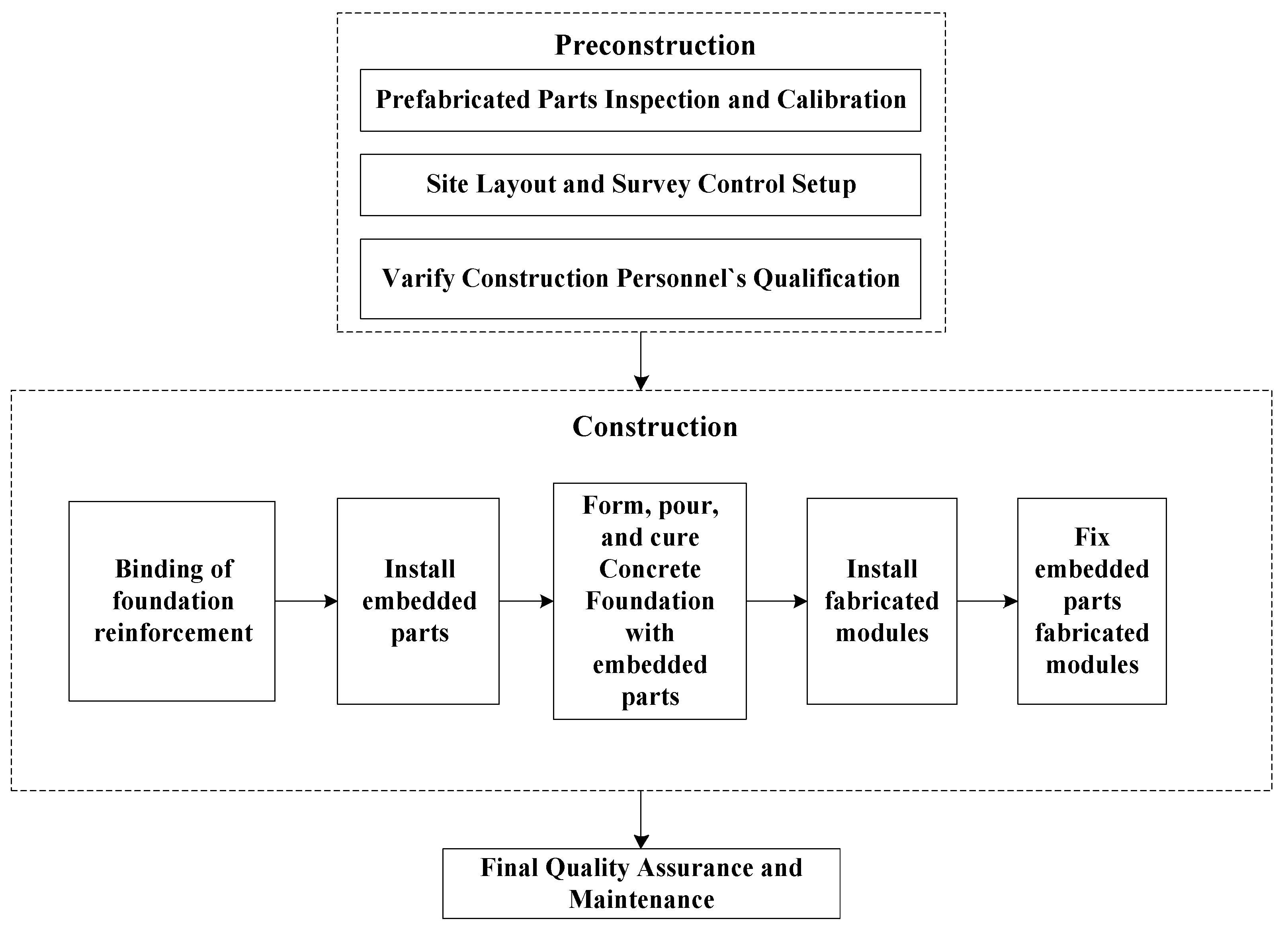
Step 2: Identify the critical quality control procedures. This study categorized the modular construction installation into three main construction phases: preconstruction, construction, and post-construction, as shown in
Figure 2.
In the preconstruction phase, first of all, quality control was carried out from the aspect of raw materials, and quality inspection was carried out on the incoming modules to ensure that the incoming modules met the corresponding quality standards and met the installation requirements, such as the size problem in the manufacture of large steel structures [
5]. The prefabricated components, including embedded parts and fabricated modules, were inspected and calibrated according to the specifications and manuals. A detailed on-site quality control plan was prepared based on the manufacturer’s recommendation. Construction equipment and construction staging area were well-planned before installation. Proper use of professional equipment can improve construction quality and significantly improve construction efficiency.
Then, the coordinates of the embedded parts were measured by the licensed surveyor on-site. The surveyor defined the position of the embedded parts’ axes via a local coordinate system. This study chose to utilize laser scanning technology for defining the location and the alignment of embedded parts. In addition, a licensed quality control manager was assigned on-site, and quality control training was provided for all construction personnel.
From the perspective of improving the quality of construction personnel for quality control, installation personnel were required to have the corresponding qualification and professional training to understand the specific construction sequence of module installation and possible problems and treatment measures.
In the construction phase, the installation process and the detailed quality control procedure of installing embedded parts and fixed fabricated modules were identified. Special attention was given to the accuracy of module positioning and calibration to ensure its levelness and alignment do not affect the construction quality of the process and its immediate aftermath. A pre-final quality evaluation was performed after the concrete foundation was cured to check the position and fabricated modules’ alignment. Supervision personnel were present for the key processes to ensure that the installation meets the standards.
In the post-construction phase, final quality assurance was conducted before the project is turned over to the owner, ensuring the quality standards are met.
Step 3: Develop BIM model. This study decided to utilize BIM and laser scanning technology to conduct a quality control process. BIM models, including embedded parts, fabricated modules, reinforcement, and concrete foundations, were created based on the design and the assembly instructions of the construction structure. Establishing a quality BIM model in this modular construction project helps the construction professionals check and solve design errors. It also ensured the project was delivered on time, and the cost is maintained.
Step 4: Capture of point cloud data. This work included selecting a suitable laser scanner, locating the scanning position, optimizing scanning methods, parameters, and removing the noise data. The scanner set-up plays a vital role in the quality of the resulting point cloud [
44]. Time-of-flight scanners are commonly used for construction engineering projects. The key benefit of this type of laser scanning technology is its long range [
44]. Alba et al. [
45] listed some time-of-flight scanners that can reach a range of more than 1 km to capture infrastructure systems, such as dams or bridges. A time-of-flight scanner was selected to capture the point cloud data.
Step 5: Data analysis and field validation. First, the noise was removed from the raw point cloud data. Then, the point cloud was georeferenced with the BIM model and was compared with the BIM model for any tolerance discrepancy outside the quality requirement. Tolerance requirements, including system alignment torsion, anchor plate elevation tolerance, the distance between each embedded parts, the distance between fabricated modules and embedded parts, and the rotation tolerance, were predefined in the BIM model for quality control. An indoor test was conducted to validate the laser scanner accuracy and optimize the selections of the laser scanning parameters. The field validation was conducted after passing the indoor testing.
4. Case Study
This study implemented the methodology in a real-life project. This modular construction project is along the Heilongjiang river, China. The length of the removable floodwall is 3135 m, with a total of 1056 prefabricated anchor plates. The purpose of installing a removable floodwall is to meet the new flood control standard without blocking the view of the skyline. Anchor plates are identical to each other with the same installation procedure of each anchor plate. The authors decided to use two sample anchor plates to describe how the quality analysis was performed in this study.
4.1. Identify Critical Quality Control Procedure
Prefabricated parts’ inspection and calibration: The removable flood wall used in this study was obtained from IBS Company, Germany, and has been applied in Germany, Austria, the UK, and China [
5].
Table 1 shows the main components and materials.
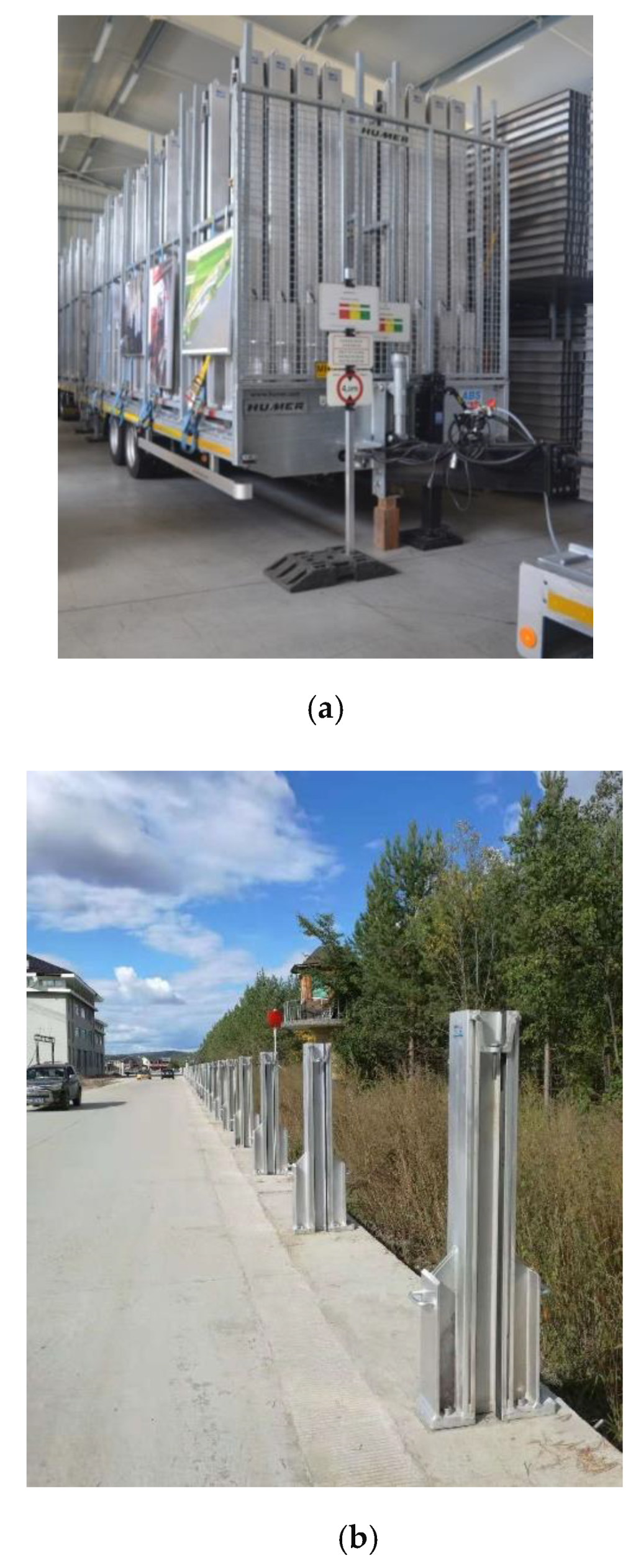
The removable floodwall consists of two permanent installed components, one is the end post, and the other is the anchor plate. It also includes four removable components: logs, ground seal, pressing tool, and center post. All of them are prefabricated and were transported to the job site, as shown in
Figure 3.
It is essential to inspect the quality and dimension of the prefabricated components. In the preconstruction phase, the research first utilized laser scanning technology to verify the anchor plates’ dimensions and then used the laser scanner to survey the construction site.
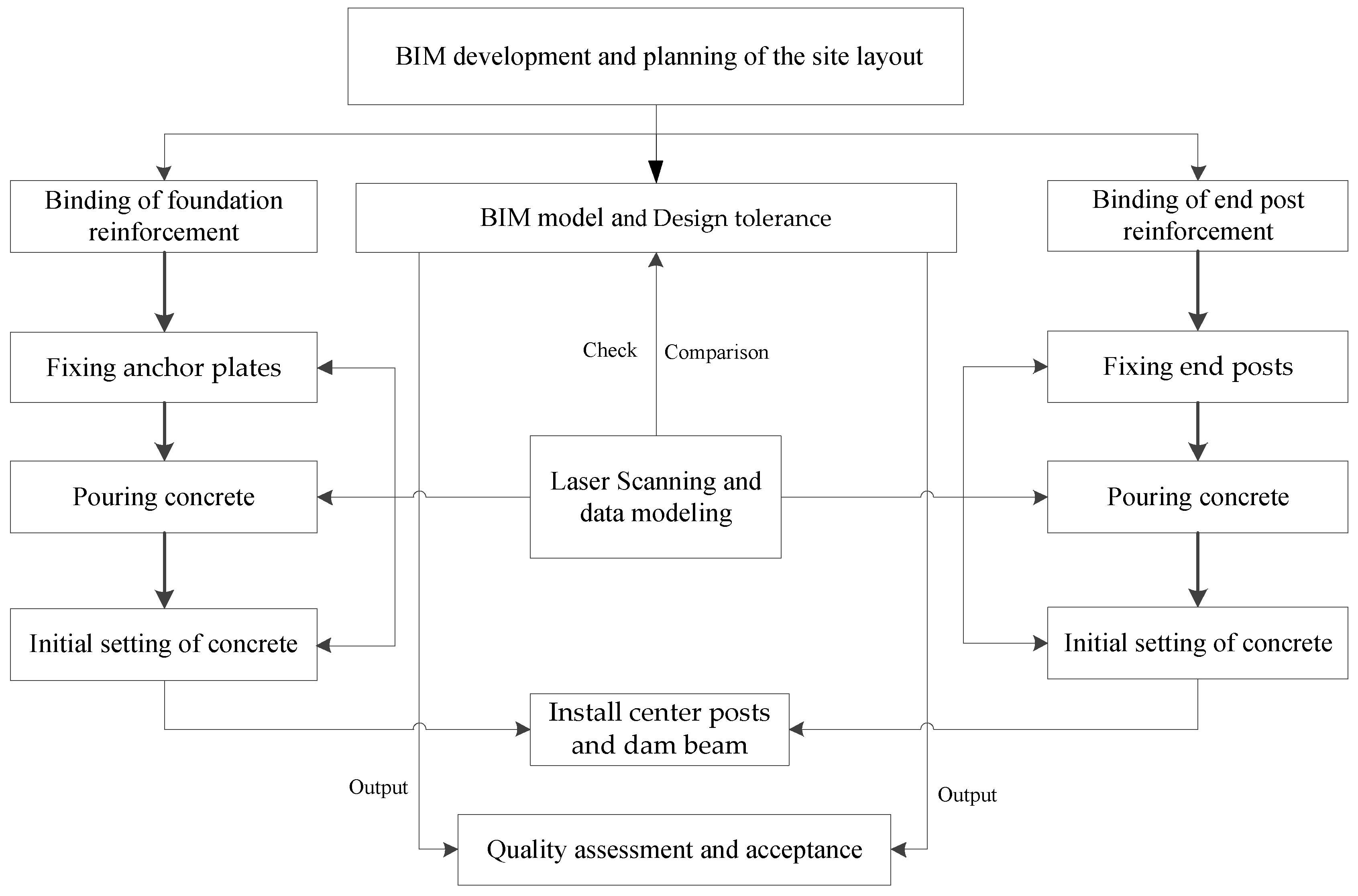
The workflow of quality control for a removable floodwall system with 3D laser scanning and the BIM method is shown in
Figure 4.
4.2. Developing a BIM Model
Based on the design and construction drawing, the research team developed three-dimensional BIM models in Revit and georeferenced them to the coordinate system used by the project. BIM technology has the potential to manage the life cycle of removable floodwall projects, and improve project quality and efficiency, reduce project cost, reworks, and wastes.
Figure 4 shows the overall modular removable floodwall components in the BIM Model.
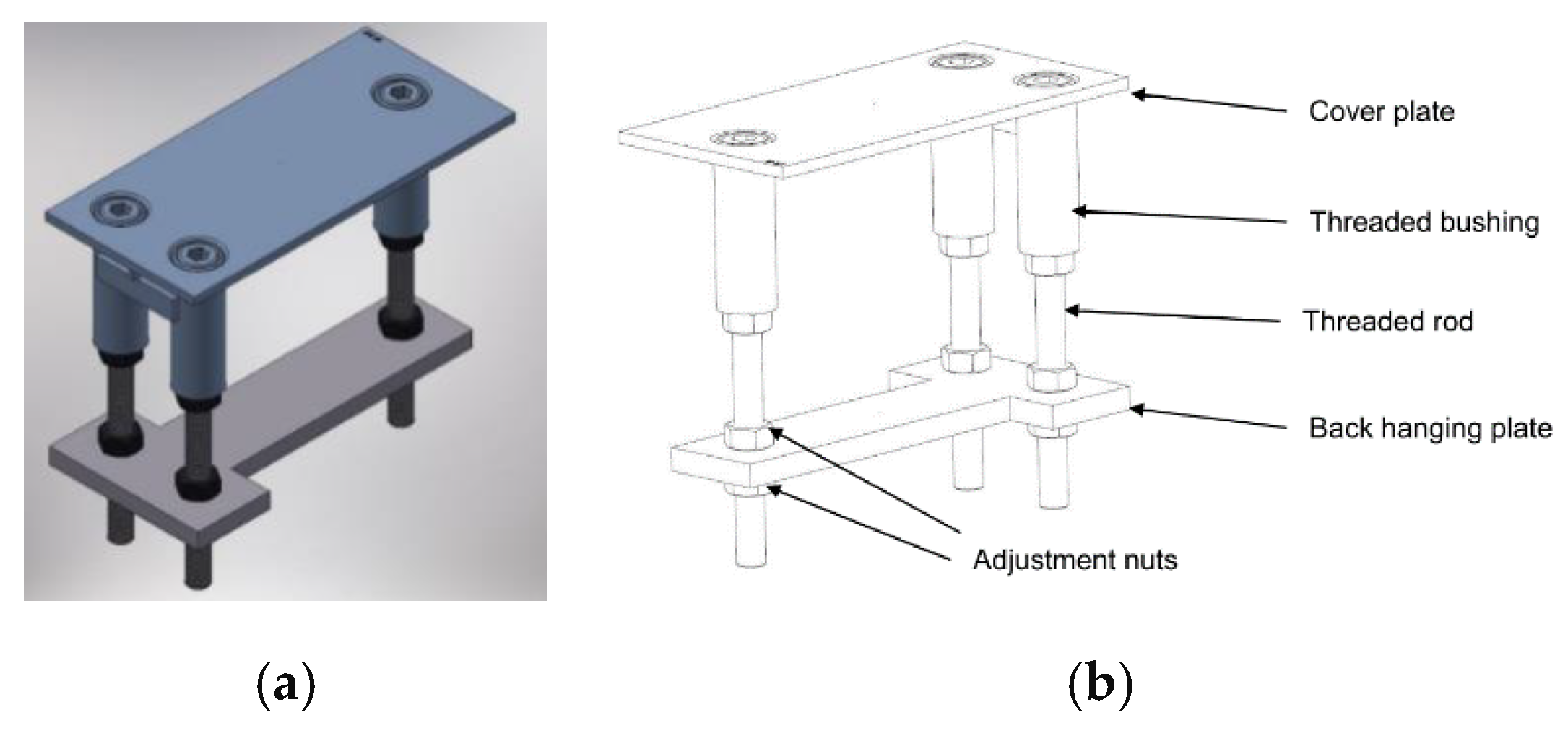
A 3D model of the anchor plate was developed, as shown in
Figure 5. The individual component of the anchor plate is shown in
Figure 6.
Figure 7a,b presents the BIM model of the reinforcement structure and the anchor plates welded to the reinforcement.
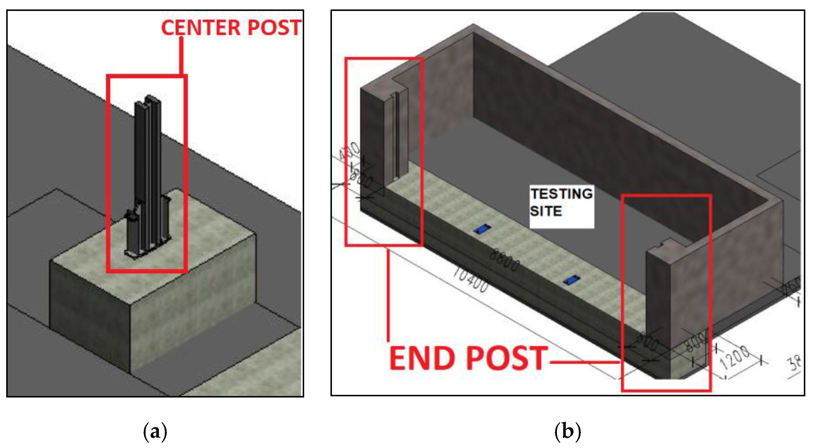
In addition to anchor plates, two other components require quality control. They are the fixed end post and center post, as shown in
Figure 8a,b.
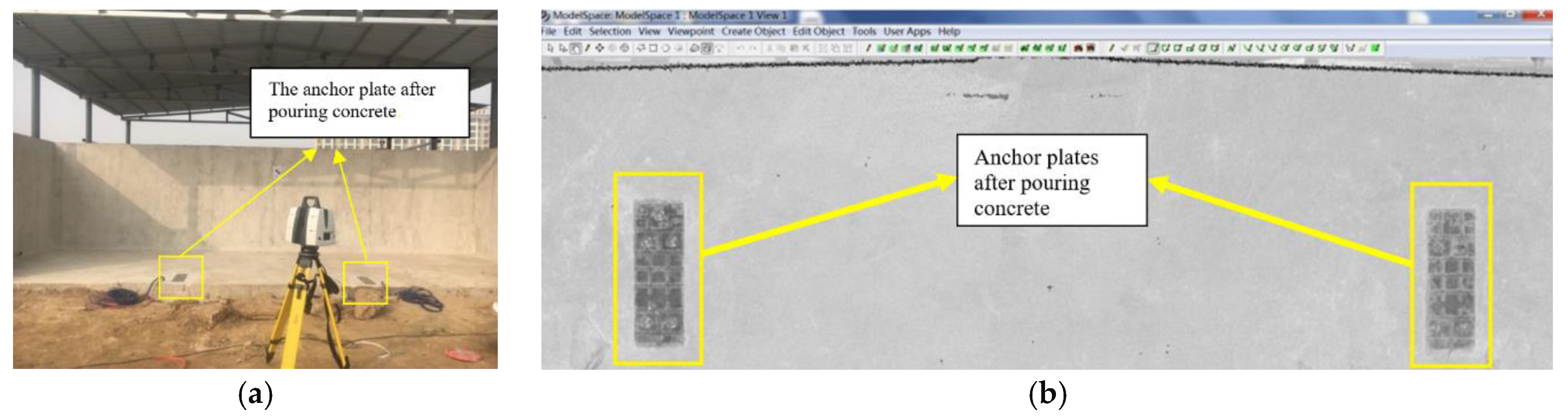
Figure 9 shows the anchor plates and the end post after pouring concrete.
4.3. Capture of Point Cloud Data
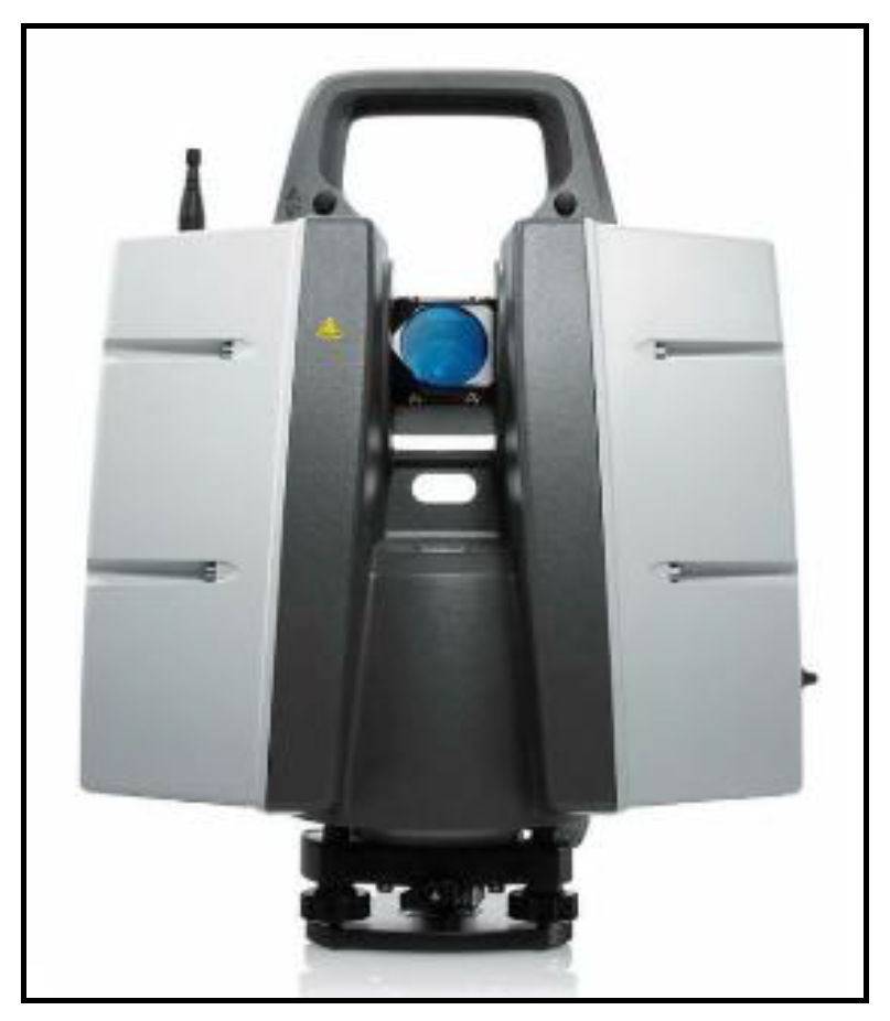
Selection of laser scanner: There are many types of laser scanners on the market. The selection of the laser scanner in the project was determined by factors such as the range and accuracy specifications of the scanner, the accuracy requirements of the project, the cost of the scanner, and the budget of the entire project. The location and the scanning parameters of the scan were crucial to maintaining a high level of accuracy. There are three key impact factors of the scanning accuracy: (1) distance to the object, (2) incident angle between the 3D laser scan and the installed anchor plates, and (3) angular resolution of the 3D laser scanner. After all of those factors were studied, the Leica P30 laser scanner, as shown in
Figure 10, was selected to capture the data. Multiple scans were then performed to minimize the occlusion effect. The instrument specification is provided, as shown in
Table 2.
When the prefabricated parts were delivered on-site, quick scans of anchor plates were performed. Their dimensions were recorded to compare with the design requirement.
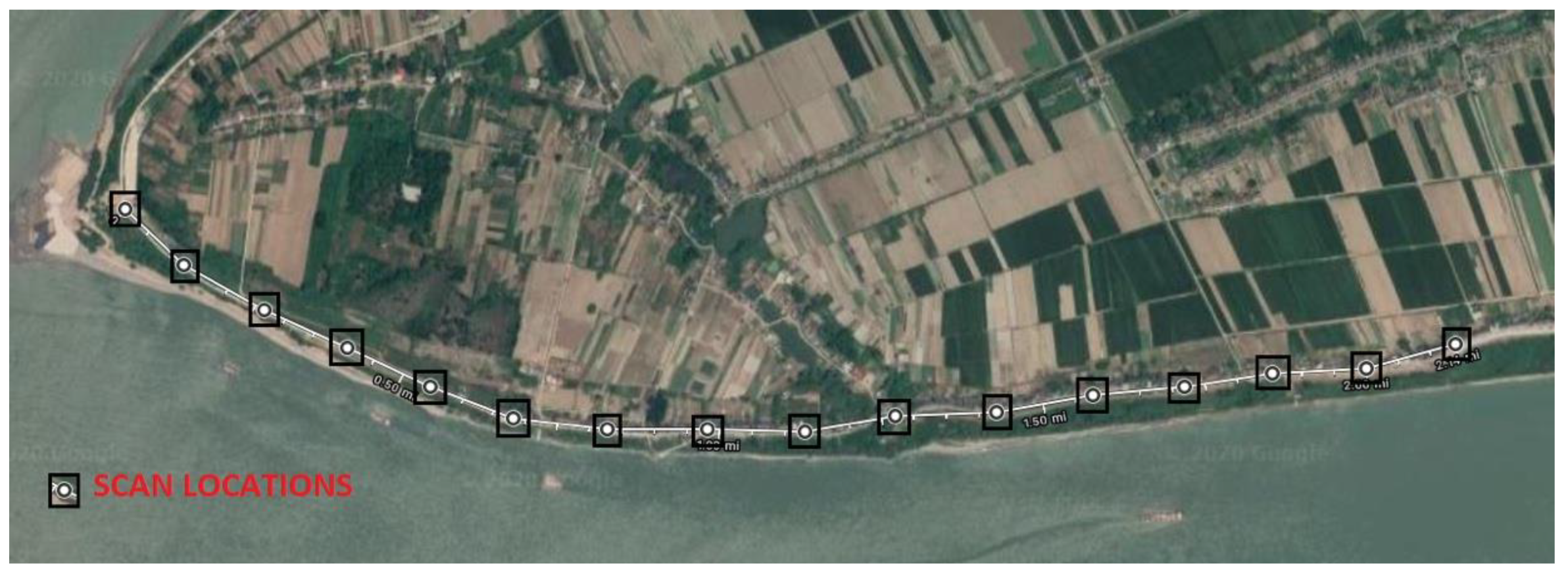
Planning of the site layout and the installation alignment: After verifying the components’ quality, the survey control and installation alignment were set up using laser scanning technology. A total of sixteen scans were performed along the riverbank. The scanning locations were carefully established before scanning was performed by evaluating three factors: (1) distance, (2) angle between the anchor plate and the scanner, and (3) angular and 3D position accuracy. Based on the range of the Leica P30, the researchers decided to scan every 200 m along with the project length of 3135 m, as shown in
Figure 11 (this picture is for illustration purposes only).
Due to the rural conditions in the construction environment, an ideal set-up is not always possible. The location of the scanner depended on the existing condition of the job site. The layout of the scanner’s location is shown in
Figure 11. In total, 16 scans were performed to define the installation alignment.
The anchor plates were installed in a reinforced concrete foundation and embedded flush with the ground. The anchor plate is used to support the center posts. In non-operative mode, the anchor plates’ internal threaded bushings are closed with dummy bolts. They protect the bushings from debris. In operative mode, the dummy bolts are removed, and service bolts are utilized to connect the center posts with the anchor plates.
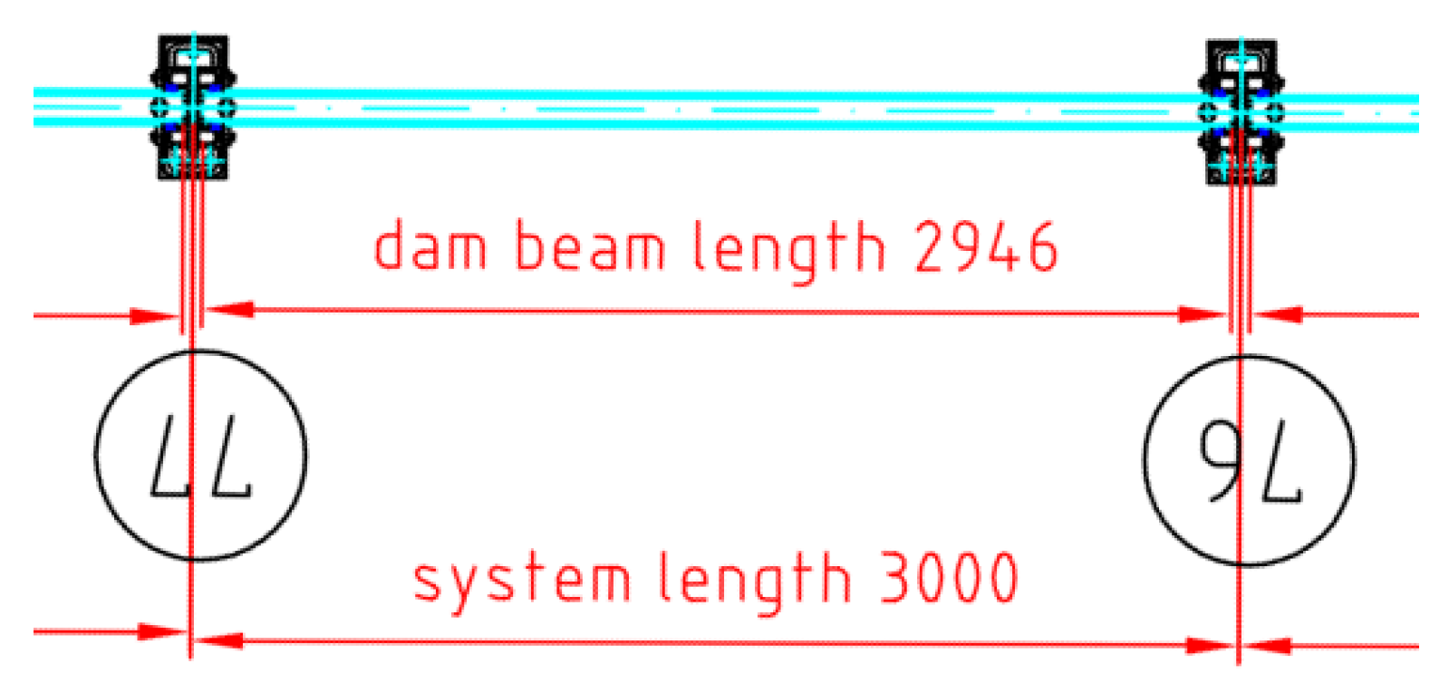
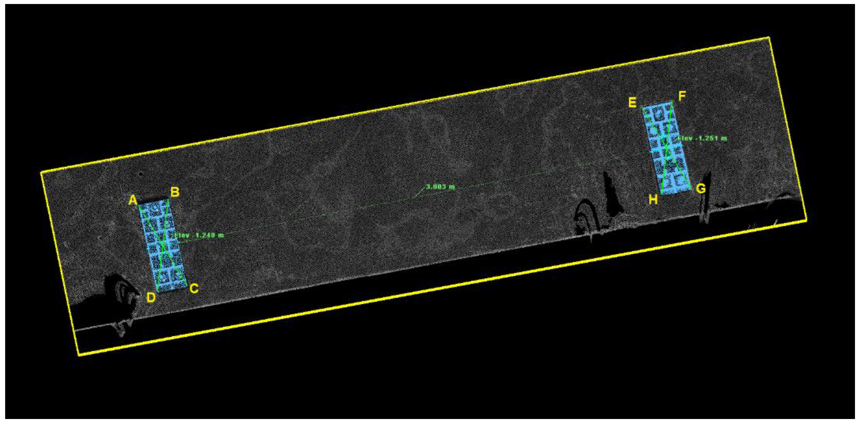
Figure 12 shows the anchor plates installed every 3 m (3000 mm, as shown in the figure) according to the plan and specification.
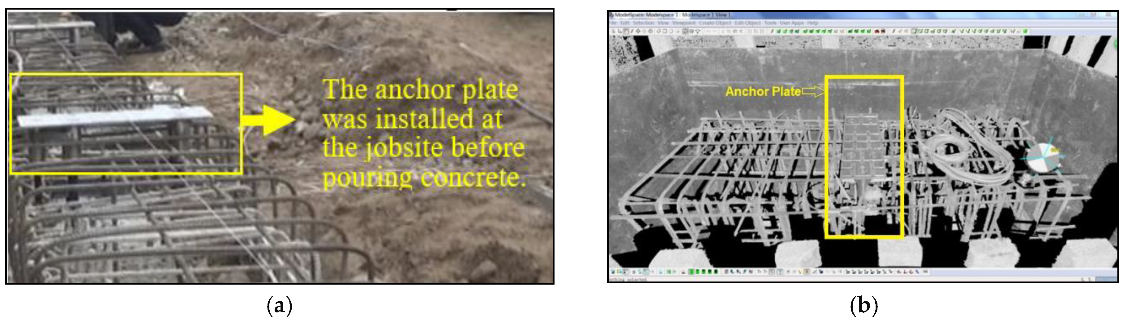
After an anchor plate was placed and levelled, it was permanently welded to the reinforcement to protect any movement during the cast-in-place process, as shown in
Figure 13a. Multiple scans were performed to capture the point cloud data. Control targets were placed manually at the recommended optimal distance from the scanner and evenly throughout the scan at different elevations, according to the operating manual. Then, point clouds were tied into a single coordinate system, as shown in
Figure 13b.
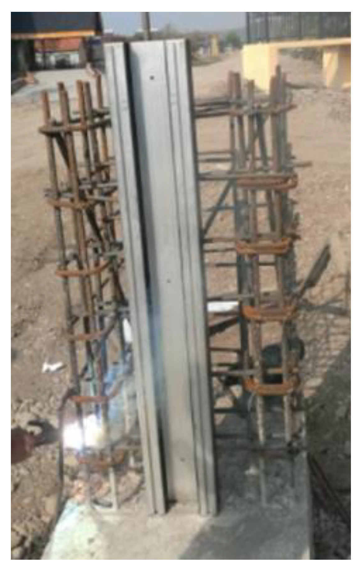
After verifying the anchor plates’ installation tolerance, end posts were welded to the reinforcement, as shown in
Figure 14, and concrete was cast in place. Then, center posts were set onto the anchor plate, and service bolts were tightened to connect posts with anchor plates. The ground seal was integrated into the log for each field. Then, logs were inserted with an integrated ground seal between posts.
When the correct position of the anchor plate has been checked and documented, concrete work is performed. After the concrete is cured, scans are conducted to capture the anchor plate’s as-built position, as shown in
Figure 15a,b. The data will be compared to the point cloud before pouring concrete to check if the position is changed due to the concrete work.
4.4. Data Analysis and Field Validation
After performing a 3D laser scan, the raw point cloud data need to be processed. Cyclone was selected as the software to process point cloud data because it is a software developed by Leica, the manufacturer of 3D laser scanner used in the study, hence avoiding compatibility problems in between the software and the equipment and avoiding the cost of purchasing a new software since Cyclone comes with the Leica 3D laser scanner.
The project used China Geodetic Coordinate System 2000 (CGCS2000) as its main georeference system. The Lecia Total Station surveyed each control point under the CGCS2000 system. The registration process of combining the 16 scans was under the 5 mm of accuracy. Once the point cloud is registered, the control points were used to georeference the entire data in the CGCS2000 system. The georeferencing accuracy is also within 5 mm. Thus, the BIM model and point cloud data were in the same coordinate system and could be compared. Due to the high density and the noise data from the original point cloud data, it was necessary to eliminate the point cloud noise and use the feature extraction algorithm to reduce the number of point clouds and the reading time of the computer. Noise data caused by material reflection was cleaned manually, and then the “region grow” function in the Cyclone was performed to smooth out the surface of the anchor plate. After that, the point cloud data were extracted and saved in IFC format for storage to facilitate comparison with BIM data.
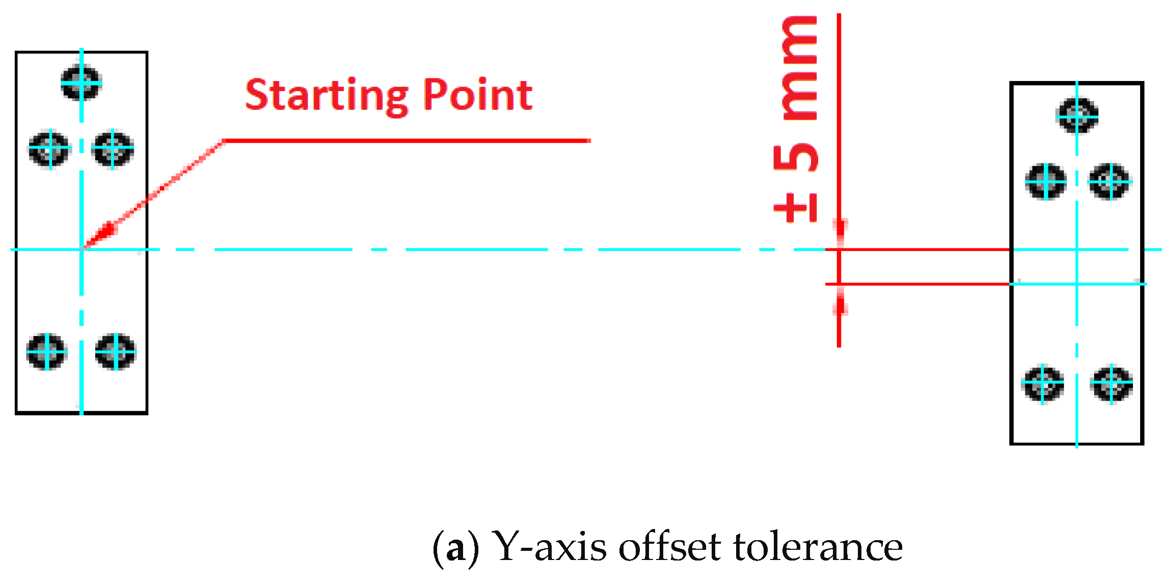
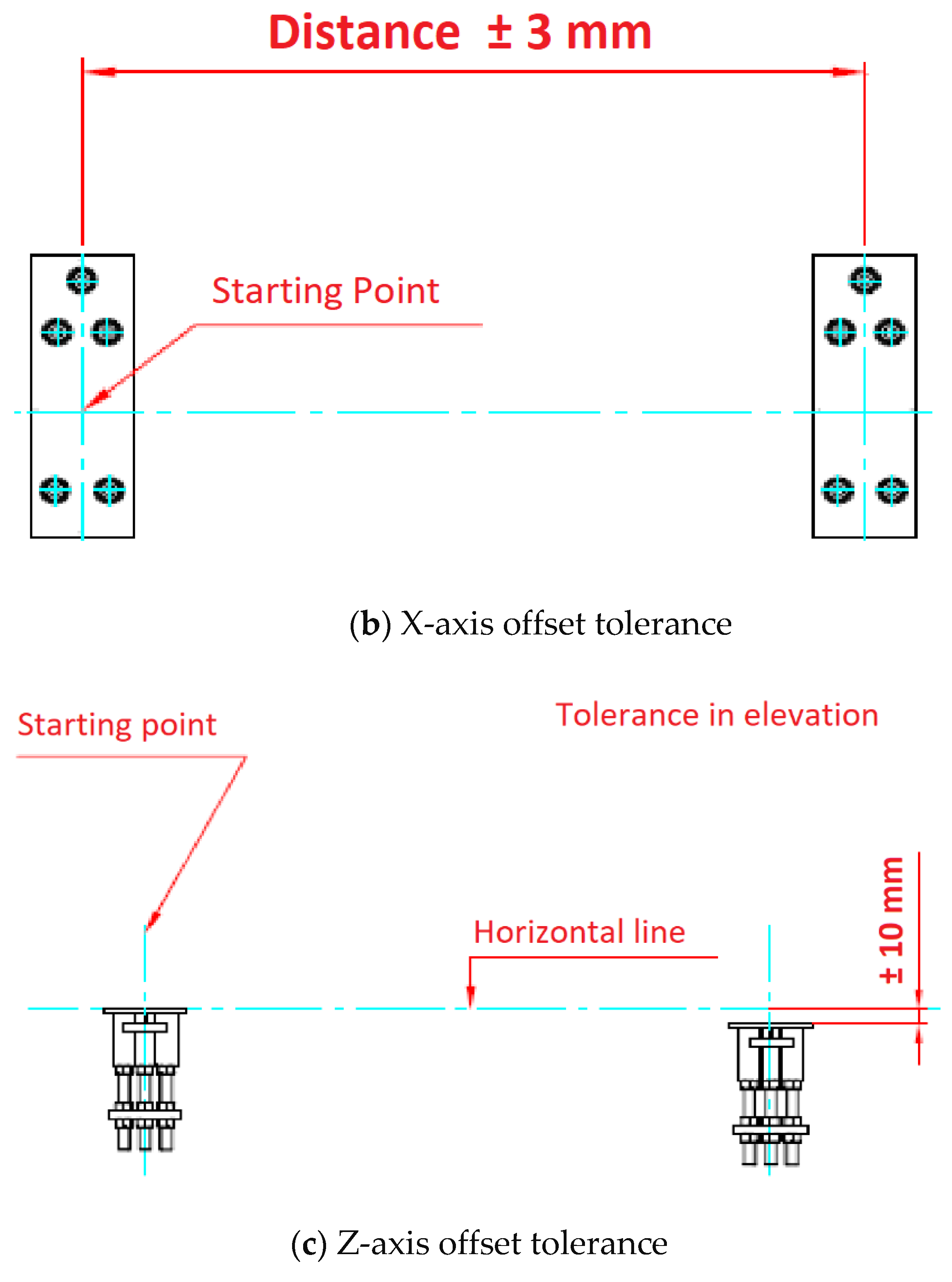
Based on the design tolerance provided by the manufacturer, as shown in
Figure 16, the offset on the
X-axis (±3 mm),
Y-axis (±5 mm), and
Z-axis (±10 mm) need to be evaluated and measured, as shown in
Figure 9. To measure the torsion deviation, each anchor plate was controlled by four check-points, which are the four corners. The errors were calculated manually by comparing the created BIM model and the scanned point cloud data, as shown in
Figure 17.
Researchers examined the distance and the offset of the three axes between the center point of the anchor plate. The required center to center distance is 3000 mm. The actual distance is 3003 mm with −3 mm on the
X-axis, 3 mm on the
Y-axis, and 2 mm on the
Z-axis. All of them met the quality requirement, as shown in
Table 3.
Table 4 shows the deviation of the control points to determine the torsion quality. The most significant deviation is 5 mm on the
Z-axis, and it is within the requirement of ±10 mm.
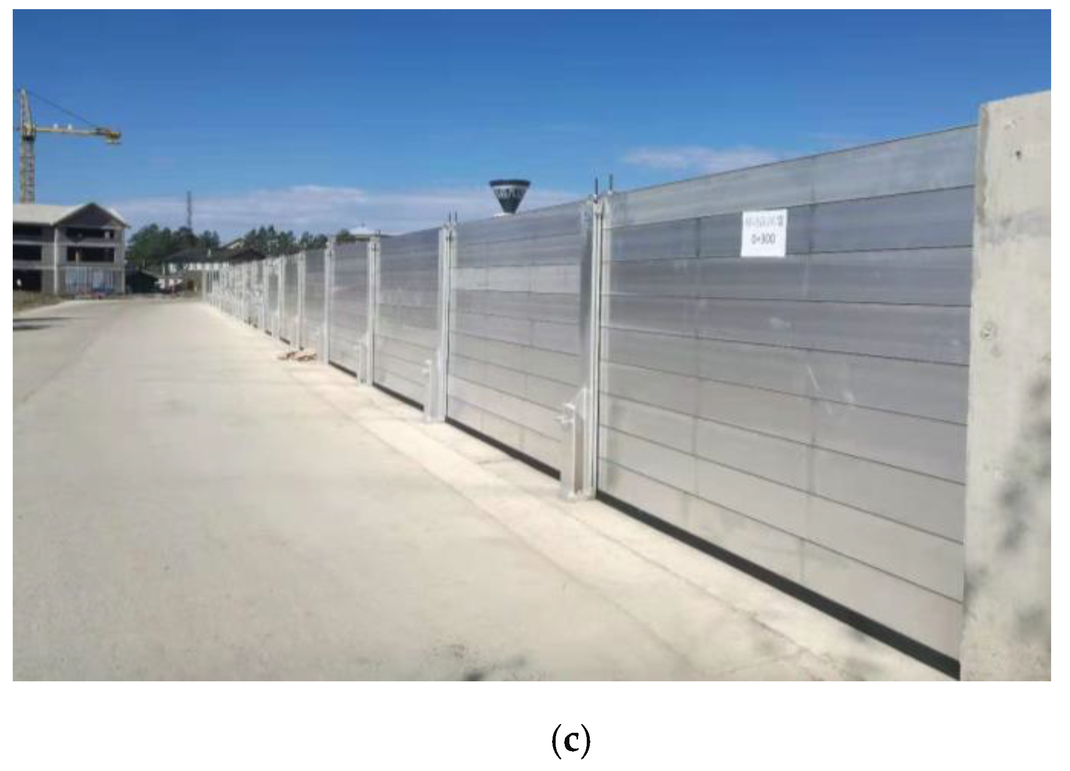
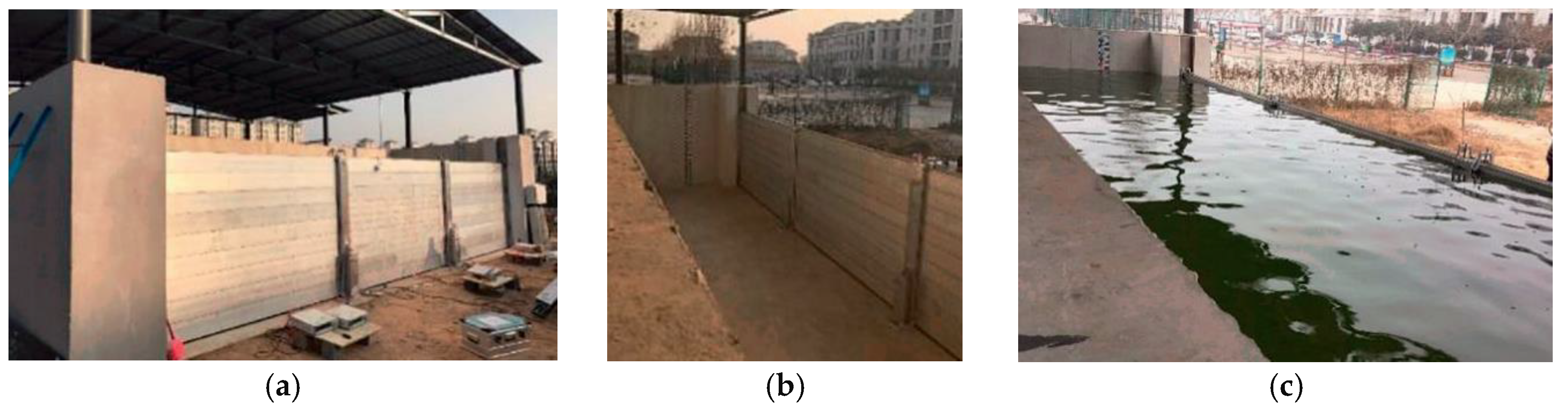
A final performance test was conducted to check the water leakage along with another structural testing before it was applied to the entire project, as
Figure 18 shows [
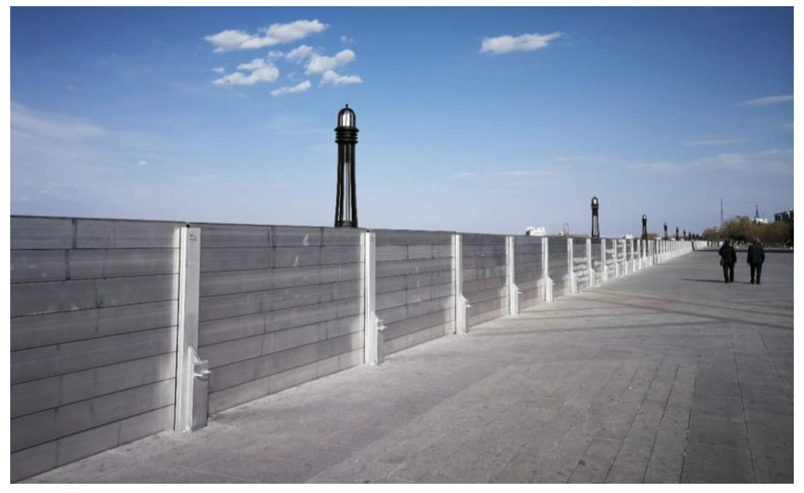
5]. The posts’ bending resistance and the seepage resistance of the removable floodwall system met the design requirements. The removable floodwall construction project was completed, as shown in
Figure 19. All the quality control tolerance was accepted.
5. Discussion
During the installation of the removable floodwall, it is found that the stage of concrete implementation is more prone to quality problems than any other process. First, the concrete process should be carried out in accordance with the processes and standards in the prepared construction plan, paying particular attention to the accuracy of the module positioning and calibration to ensure its elevation, level, and perpendicularity, so as not to affect the quality of the construction of this process. Then, rigorous quality control is required to perform at the level of millimeters. Current quality control is done by manual means such as rulers and latitude and longitude meters, which are time-consuming and inaccurate in measurement. It is difficult to measure accurately in high-rise locations or harsh environments, and it takes a lot of time and effort to do so. This study first uses BIM to construct a model to form a reference point for quality control. A 3D laser scanning of the construction site is used to form an actual model of the structure. By comparing the two models, an evaluation of the quality tolerance of the modular construction is performed. The construction site adjusts the modules according to the comparison results until the final quality control requirements are met. As there will always be changes at the construction site, there will be differences from the initial design BIM. Therefore, the point cloud data can also be used to modify the BIM model and ultimately become the final as-built model of the structure.
The embedded components are the connections of a modular structure, an essential part of modular construction. The embedded parts’ location determines the quality of the components and the installation quality of the entire structure. The quality control of modular construction is divided into quality control of prefabricated component production and installation quality control. Kim et al. [
7] studied the method of evaluating the dimensional and surface quality of prefabricated components based on BIM and 3D laser scanning. The quality of on-site installation, however, is more difficult to control. The non-contact quality control method based on BIM and 3D laser scanning designed in this paper is of general interest. It can be fully extended to modular buildings’ whole life cycle, including design, build fabrication, installation and operation, and maintenance. The processing of point cloud data is at the core of using laser scanning for fine-grained quality management. Also, the process of registering point cloud data and removing noisy data to meet the quality control requirement plays a key factor in the success of quality management.
A detailed comparison was performed between the standard quality control procedure and the proposed 3D laser scanning and BIM method. The number of workers needed, the measuring time, and the level of accuracy were documented and compared. The results are shown in
Table 5.
Compared with the traditional model, the method proposed in this study has two main advantages: (1) it realizes collaborative management of the whole construction process. The problem solving of the construction process is no longer unilateral. Many stakeholders are involved. (2) In terms of construction quality control, a more accurate and efficient laser scanning and BIM inspection method are integrated, reducing the quality inspection time of the entire construction process, avoiding on-site rework, and providing more reliable data support for the construction problems. With the increasing level of information technology in the industry and the continuous innovation of project management models, this method will be more valuable throughout the project life cycle by adding control elements and expanding management stages.
The economic feasibility of the proposed quality control system was discussed in the context of other laser scanning applications. The cost of purchasing and deploying one or several laser scanners is not trivial. If one compares the traditional quality control method and the method of applying laser scanning and BIM in modular construction quality control, it may be cheaper to use the traditional method. However, laser scanning technology brings many benefits to the project, with quality control being only a minor one. Laser scanning can be used for multiple purposes, including measuring distances and clearances, communicating between stakeholders, referring to recorded data for operation, maintenance, and renovation/rehabilitation, and automating construction progress control [
44]. Quality control with laser scanning and BIM can be economically feasible when used alongside other applications such as generating a detailed record of the construction or measuring clearances.
One of the limitations of this study is the training. Many workers on the jobsite are not familiar with laser scanning and BIM. It takes time to train those workers to operate the laser scanner and have the data processed. This can be improved in the future by using a laser scanning specialist and automating the data process. In addition, besides the terrestrial laser scanner, there is a variety of tools that can be used to collect point cloud data. For a linear project, such as a removable floodwall, a mobile laser scanning system could be a good selection, which can reduce the time of capturing point cloud data. This research established a solid framework for using laser scanning and BIM for modular construction quality control. However, the full potential of digital modeling and automation processes can be expanded in the future.
6. Conclusions
Quality control is essential to a successful modular construction project. It should be enhanced throughout the project, from design to construction and installation. Modular construction requires prefabricated components to be delivered and inspected before storing in a secure place to avoid deterioration from water, moisture, and other weather elements. A good quality control program will prevent costly repairs after the project is completed. Handling large-scale modular projects requires extensive planning, quality control, and contingencies. The main challenges are the feasible logistics plan, quality control, and commissioning. This study built a framework of integration of BIM and 3D laser scanning technology to perform quality control of the prefabricated modular construction projects. A case study of installing a removable floodwall was presented to validate the process. The critical quality control procedure was first established to layout when and what component needs to be checked. BIM technology was used to establish an accurate three-dimensional model according to the design and specification. 3D laser scanning technology was used to determine the entire removable floodwall’s alignment to scan anchor plates and end posts before and after pouring concrete. Based on the tolerance requirements, a comparison was performed between the point cloud and BIM model to determine whether the discrepancy was within the allowable range. A series of rectifying measures were carried out for the components beyond the allowable range of tolerance to ensure the construction and installation quality.
This method improved the efficiency and accuracy of modular construction quality control. It established a preliminary foundation for using BIM and laser scanning to conduct quality control in removable floodwall installation. Also, it provided a reference for the combined application of BIM and 3D laser scanning in modular construction quality control research.
In future work, a robust system will be developed to automatically extract the key points such as the center point, corners, and alignment of the embedded parts for further comparative analysis. The combination of BIM and 3D laser scanning in the whole process will significantly reduce the time consumption of manual measurement and avoid manual measurement error. It can sufficiently improve efficiency while ensuring quality control precision, and finally, achieve comprehensive automatic quality control. How to build an automated algorithm to get more accurate dimensions of anchor plates is the future research direction.


