Article

Finite Element Analysis and Investigation on Spinning of Quadrilateral Parts with Hollow Cross-Sections Based on Hypocycloid Theory

1
School of Mechanical and Aerospace Engineering, Jilin University, Changchun 130025, China
2
Changchun Equipment & Technology Research Institute, Changchun 130012, China
3
College of Mechanical and Electrical Engineering, Changchun University of Science and Technology, Changchun 130022, China
*
Author to whom correspondence should be addressed.
Appl. Sci. 2020, 10(23), 8588; https://doi.org/10.3390/app10238588
Submission received: 7 November 2020 / Revised: 26 November 2020 / Accepted: 26 November 2020 / Published: 30 November 2020
(This article belongs to the Section Mechanical Engineering)

Abstract

:

Featured Application

Authors are encouraged to provide a concise description of the specific application or a potential application of the work. This section is not mandatory.

Abstract

This paper presents research on a new high-efficiency, non-circular spinning method based on hypocycloid theory. The trajectory of the roller during the forming process was derived, and the non-circular spinning process was simulated in ABAQUS 2016/Explicit. The distribution of von Mises stresses and equivalent plastic strains after each spinning pass were analyzed. The spinning quality was also investigated. This research proves the feasibility of spinning the workpieces of a non-circular cross-section using hypocycloid theory. This new non-circular spinning method can be used in practice to produce workpieces with a specific geometry and to increase the rotational speed of the workpiece from 60–240 rpm to 600 rpm, thereby improving the efficiency by around 2.5 times while maintaining acceptable forming quality.

1. Introduction

Metal spinning is an advanced manufacturing process that involves little or no cutting. The tool, such as a spinning roller, is pressed against a metal sheet or metal tube to produce continuous local plastic deformation of the workpiece and gradually form the required rotary part [1]. Spinning technology is generally used for forming hollow parts with circular cross-sections. Since the 1980s, researchers around the world have proposed a variety of non-circular spin forming methods to broaden potential metal spinning applications. Current spinning methods for noncircular parts can be classified into two types: synchronous spinning and force-controlled spinning.
In synchronous spinning, the rotation angle of the workpiece is synchronized with the radial feed of the roller. Amano and Tamura (1984) achieved elliptical cone spinning using equipment comprised of a cam and links, representing the first proof-of-concept that metal spinning technology can be used to form non-circular products [2]. Later, Gao et al. (1999) realized elliptical cone spinning using a cross-slot mechanism to generate the required radial motion of the mandrel. Relative movement between the rollers and mandrel resulted in an elliptical trajectory [3,4]. Building on the work of Amano and Tamura (1986), Gao et al. (1999) replaced the motion of the roller with a mandrel. However, both of these early methods were limited to spinning workpieces with an elliptical cross-section.
More recently, Xia et al. (2010) introduced the profiling driving method. A pair of gears is used to synchronize the radial movement of the roller and the rotation of the mandrel, and the device was shown to successfully form parts with polygonal cross sections [5,6]. Shimizu (2010) developed a non-circular spinning device that used stepping motors to synchronize the radial feed of the roller and the rotation of the mandrel, while errors in the process were tracked by software [7]. Sugita (2012) developed a synchronous, multi-pass metal spinning method and successfully obtained a square cup with a non-circular bottom [8,9]. Similarly, Arai (2018) used an intermediate circular shape to form a square cup with an oblique bottom and vertical sidewalls, and the wall thickness distribution of the workpiece was relatively uniform [10].
Force-controlled spinning controls the spinning force in the radial direction to ensure the workpiece fits over the non-circular mandrel until the non-circular parts are complete. Arai (2005) produced non-circular parts with a force feedback spinning device, in which the forming roller was driven by servo motors and the motors were controlled by a computer system to maintain a constant pushing force on the workpiece [11]. Awiszus and Meyer (2005) developed a non-circular spinning device that used spring tension to control the forming force [12]. Arai (2006) also introduced a non-circular spinning device that relied on linear servo motors to drive the forming roller, which was found to reduce the forming time [13].
In all of the methods described above, the workpiece requires a mandrel. In force-controlled spinning, control of the forming force results in an unstable roller motion trajectory. In synchronous spinning, the radial feed of the roller must be synchronized with the rotation angle of the workpiece during synchronous spinning, and the rotation speed of the workpiece must be lower than 60 rpm.
In the present study, a non-circular spinning method without a mandrel is adopted. Two rollers are arranged on the principal axis of the roller, which is then synchronized with the principal axis of the workpiece. Relative motion between the roller and the workpiece is used to spin the workpiece. The radial feed of the principal axis of the roller does not need to be considered on each pass during the spinning process. Furthermore, the rotation speed of the workpiece and the accuracy of the roller trajectory are both guaranteed.
Herein, the roller trajectory is deduced, and a reasonable, three-dimensional (3D) model, established using the finite element method (FEM), is presented. The spinning process was simulated in the FEM proposed model. The distributions of equivalent von Mises stresses and the equivalent strains of each pass were analyzed, as well as the distribution of the workpiece’s thickness and the positions of dangerously thin sections. The simulation results show that the novel non-circular spinning process is effective. This study provides an important reference for the selection of experimental parameters and the future production of non-circular parts using the proposed method.

2. Research Method

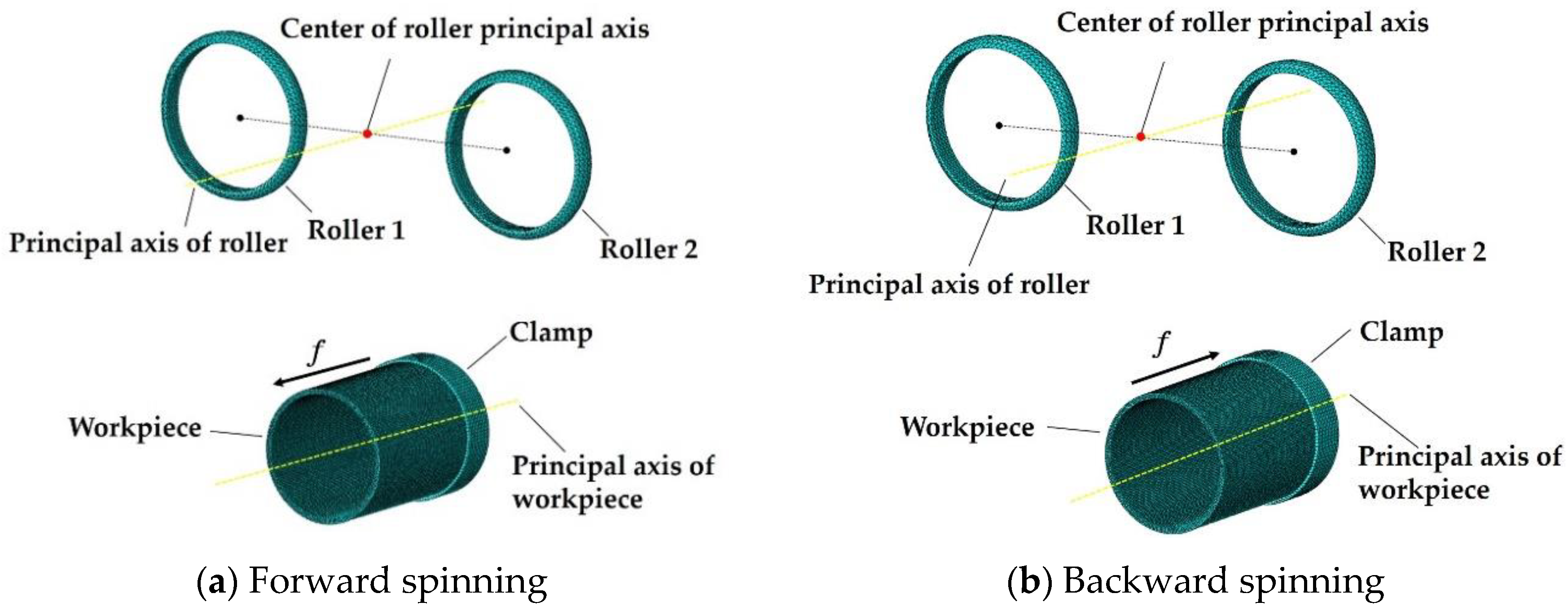
2.1. Establishment of the Finite Element Model

The 3D FEM model of the novel non-circular spinning method is shown in Figure 1. Simulations were performed in ABAQUS 2016/Explicit. To shorten the simulation time, a simplified model was adopted. The rotation of the workpiece and the principal axis of the roller were first transformed into a stationary workpiece, with two rollers arranged symmetrically on the principal axis of the roller which rotated and simultaneously revolved around the workpiece.
In the 3D model, a clamp with a width of 20 mm was affixed, and the workpiece was connected to the clamp using the tie function. Deformation of the clamped section of the workpiece was constrained, while other areas of the workpiece deformed during the spinning process. The rollers and the clamp were defined as rigid bodies, and the centers of the rollers were connected with the center of the roller principal axis using the hinge function.
In order to realize movement of the rollers in a hypocycloid manner, the boundary conditions were defined as the angular velocity of the rollers’ principal axis around the workpiece and the rotational velocity of the rollers’ principal axis. The feed rates of the rollers in the axial direction were also input.
The total length of the workpiece was set to 110 mm, the diameter was set to 80 mm and the thickness was set to 3 mm. The workpiece was then discretized into eight node hexahedral elements. In order to improve simulation accuracy, the deformed section of the workpiece was refined, with an element length of 1.25 mm along the axial direction and 0.75 mm along the thickness direction, and the angle between the two sides of the mesh was set to 1.8° along the circumferential direction. In the clamped section of the workpiece, the element length was 2 mm along the axial direction, and the other two dimensions were the same as those in the deformed section. The total number of elements was 70,752, and the number of nodes was 89,445.
The workpiece materials were composed of 6061 aluminum alloy, and the mechanical properties are presented in Table 1. The relationship between the true stress and strain was Y = 229.88 0.25 . The Coulomb friction coefficient between the workpiece and the rollers was 0.1.

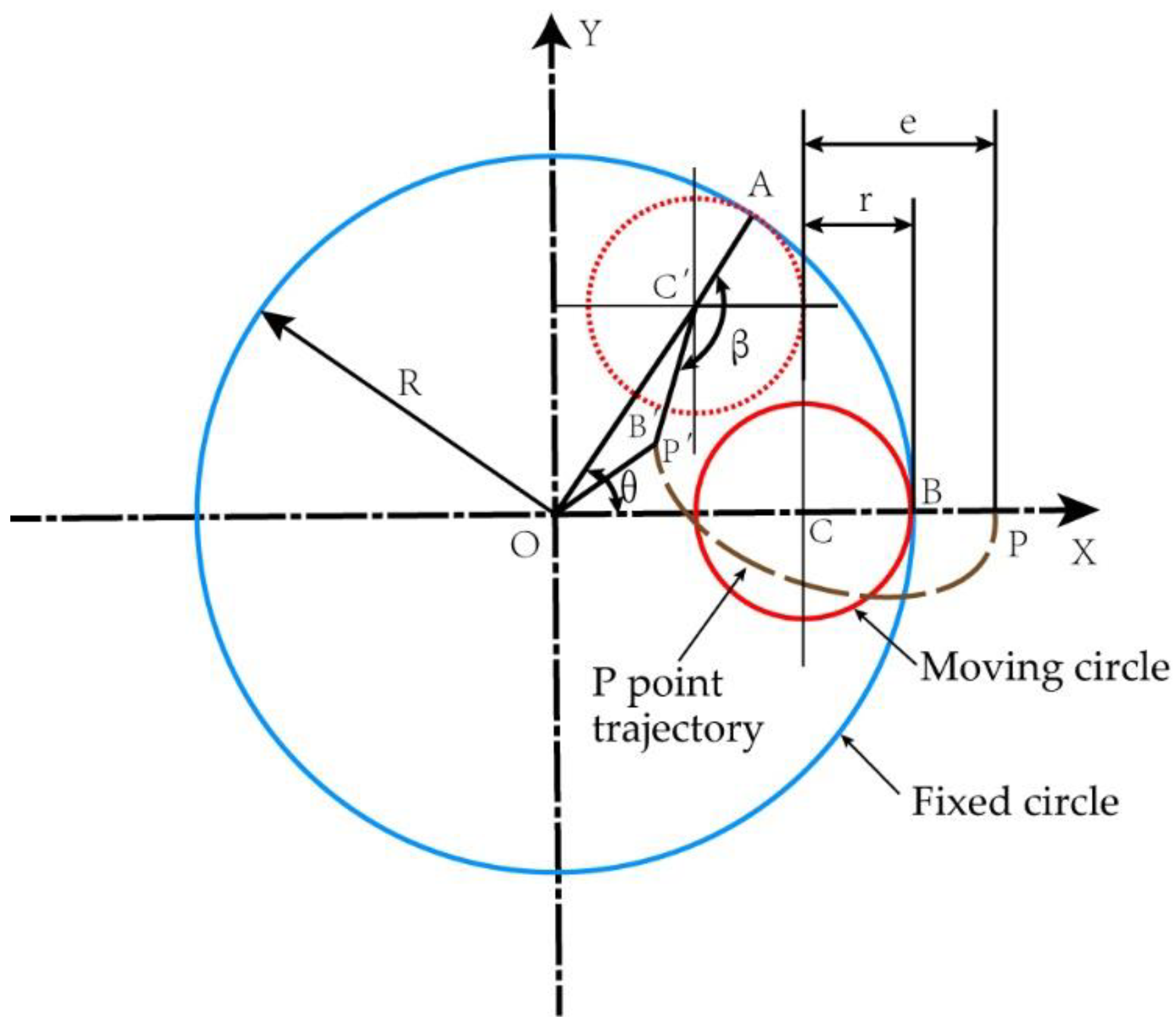
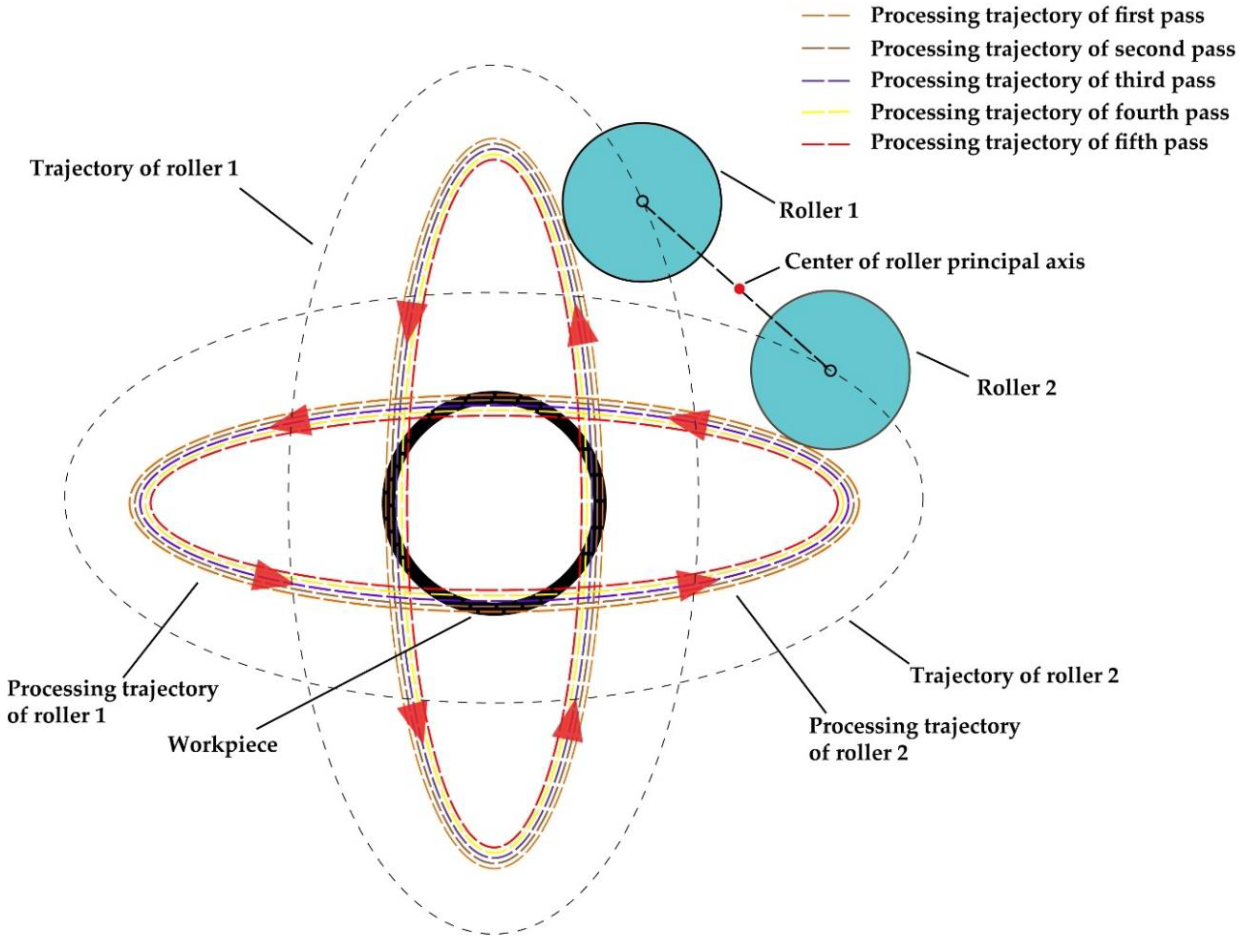
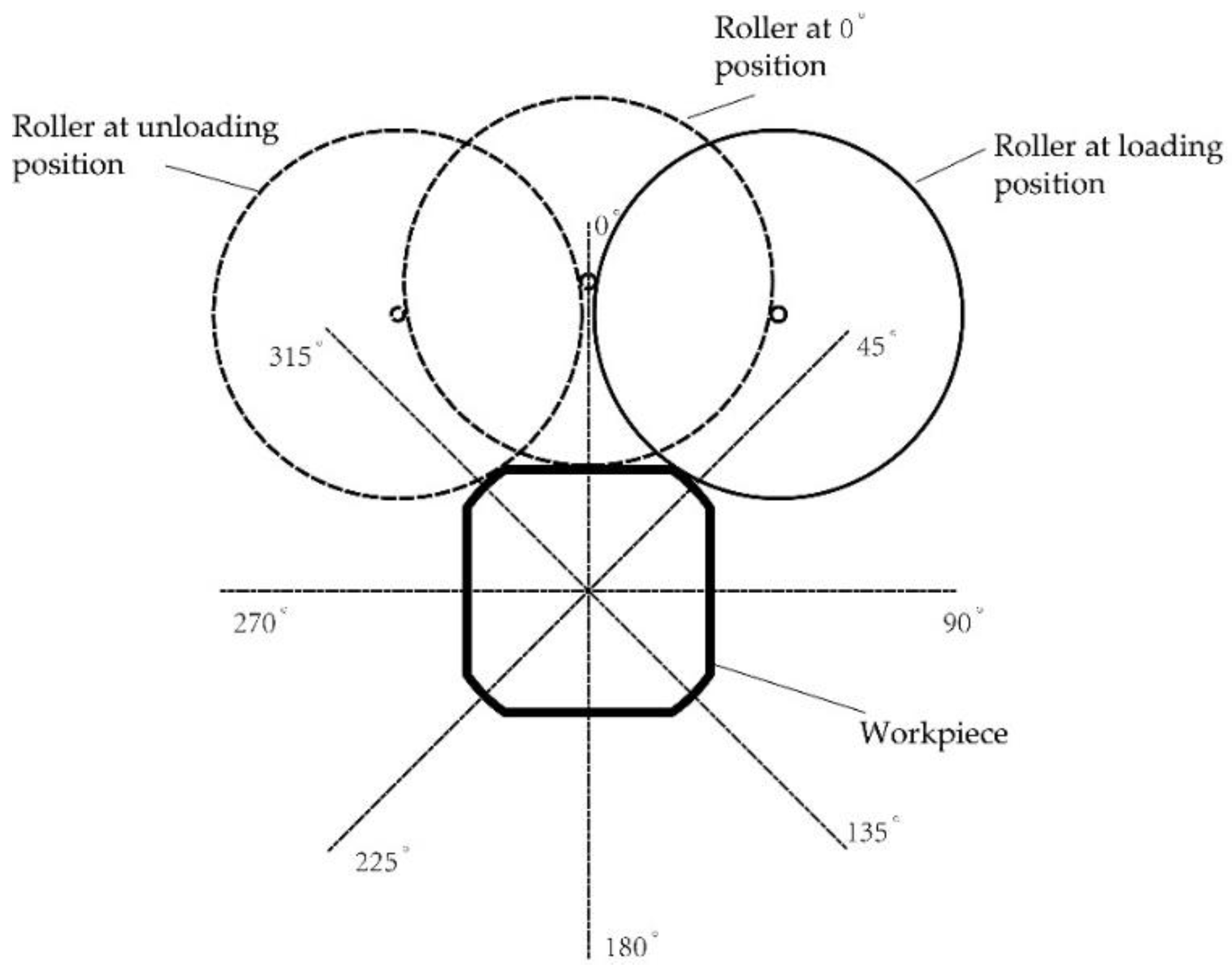
2.2. Analysis of the Roller Trajectory

The novel non-circular spinning method is based on hypocycloid theory and relies on the relative motion between the workpiece and the rollers to process the workpiece. Analysis of the roller trajectory is key to determining whether the simulation achieves accurate results.
In mathematics, the hypocycloid can be defined as follows: when a moving circle is inscribed on a fixed circle and rolls along the fixed circle without sliding, the trajectory of any point on the moving circle is a hypocycloid [14,15]. If the roller is regarded as a mass point and set as point P, then the trajectory of the roller can be derived by setting the radius of the fixed circle as R, the radius of the moving circle as r, P as a point fixed on the moving circle and the distance from P to the center of the moving circle as e. As shown in Figure 2, the center of the fixed circle is O, the center of the moving circle is C, the unit vector of the X axis is i and the unit vector of the Y axis is j . Initially, point P coincides with the X axis. Upon rotation, the contact point of the fixed circle and the moving circle is A, the center of the circle C becomes C and point P moves to P . Then, C must be at the radius OA of the fixed circle. The following expressions can be defined:
O P = O C + C P
If
θ   =   ( i , O C ) ,   β   =   ( C P , C A )
Then
O C   =   i ( R r ) cos θ   +   j ( R r ) sin θ ,
R θ   =   AB   =   AB   =   r β
Thus,
β   =   R r θ
The directionality angle between C P and the X axis is
( i ,   C P ) =     θ β =   r R r θ  
| C P |   =   e ,
Therefore,
C P   =   i e cos r R r θ   +   j e sin r R r θ   =   i e cos R r r θ j e sin R r r θ
O P =   O C + C P =   [ ( R r ) cos θ   +   e cos R r r θ ] i   +   [ ( R r ) sin θ   e sin R r r θ ] j
Equation (9) is the hypocycloid equation of the rollers. By setting the coordinates of reference point P as (x, y), Equation (9) can be used to obtain the parameter equations of reference point P (which is also the parameter equation of the hypocycloid equation), expressed as
{ x = ( R r ) cos θ +   e cos R r r θ y = ( R r ) sin θ   e sin R r r θ ( < θ < + )
When R = 2r, the equation becomes
{ x = ( r + e ) cos θ y = ( r e ) sin θ ( < θ < + )
Additionally, the parameter equation of reference point P becomes the elliptic equation.

2.3. Non-Circular Spinning Based on the Hypocycloid Equation

Using the hypocycloid equation for spinning non-circular parts, the principal axis of the workpiece and the principal axis of the roller rotate simultaneously, which means the two parallel principal axes rotate at a fixed ratio to ensure the roller trajectory follows a hypocycloid motion. The rollers rotating around the principal axis could be modeled as a fixed point on the moving circle of the hypocycloid, and the principal axis of the roller revolving around the workpiece was the fixed circle of the hypocycloid. Finally, the trajectory of the roller relative to the workpiece was the hypocycloid.
At present, there are two methods of non-circular spinning based on hypocycloid theory. One method installs a single roller on the principal axis of the roller, and the regular polygon is processed by setting different relative rotation speeds between the two principal axes. The other method installs multiple rollers at symmetrical positions on the principal axis to process regular polygons.
During the spinning of quadrilateral hollow parts, two rollers were installed at symmetrical positions on the principal axis of the roller, as illustrated in Figure 1. The trajectories of the two rollers created two mutually perpendicular ellipses, as shown in Figure 3. If the coordinates of the first roller are ( x 1 , y 1 ), and the coordinates of the second roller are ( x 2 , y 2 ), then the trajectory equation of the two rollers can be expressed as
{ x 1 = ( r + e ) cos θ y 1 = ( r e ) sin θ x 2 = ( r e ) cos θ y 2 = ( r + e ) sin θ
During the process, the two rollers spun with multiple passes, and the principal axis of the roller was fed in the radial direction after every pass, as shown in Figure 3. The processing trajectories of the two rollers show how the workpiece was gradually transformed from a tube into a quadrilateral part via the continuous radial feed with each pass.
This new method of quadrilateral non-circular spinning differs from previous quadrilateral non-circular spinning approaches, in which the radial feed was mainly driven by the motor, and the rotation speed of the workpiece was generally set to between 60 and 240 rpm to ensure synchronization between the workpiece rotation and radial feed. Conversely, the rotation rate of the workpiece could be set to 600 rpm using the newly proposed non-circular spinning process theory. Since synchronization between the workpiece rotation and the radial feed did not need to be considered, only the principal axis of the workpiece was synchronized with the principal axis of the roller. This condition was easier to achieve and, therefore, the accuracy of the radial feed of the roller could be assured, and the efficiency of the non-circular spinning process was greatly improved.

2.4. Selection of Spinning Parameters

Five passes were adopted for the simulations. For multi-pass spinning, both the forward and backward paths were adopted, as shown in Figure 1, which avoided excessive thinning or thickening of the workpiece during the spinning process.
The starting point of each forward pass was 30 mm from the clamp, thereby ensuring the clamping constraint did not affect the spinning process. The starting point of each backward pass was 5 mm away from the free end of the workpiece. Since the free-end edge shape was not regular after spinning, if the roller were loaded at the edge in the beginning of the backward pass, this would result in an uneven spinning force on the workpiece, which would affect the forming quality.
Many factors can affect the spinning process of quadrilateral hollow parts, including the feed rate in the axial direction, the diameter of the roller, the roundness radius of the rollers, the radial feed of each pass, the rotation speed of the principal axis of the workpiece, the rotation speed of the principal axis of the roller and the distance between the center of the roller and the center of the roller’s principal axis. The last two parameters are unique to this new method. The parameters selected for the simulations are listed in Table 2.

3. Results and Discussion

To better describe the simulation results, the spinning process were defined as follows. As is shown in Figure 4, the position where the roller began loading the workpiece to the 0° position was called the first half loading stage, and the position from the 0° position to the roller unloading the workpiece was referred to as the second half loading stage.

3.1. Analysis of Stress Distribution

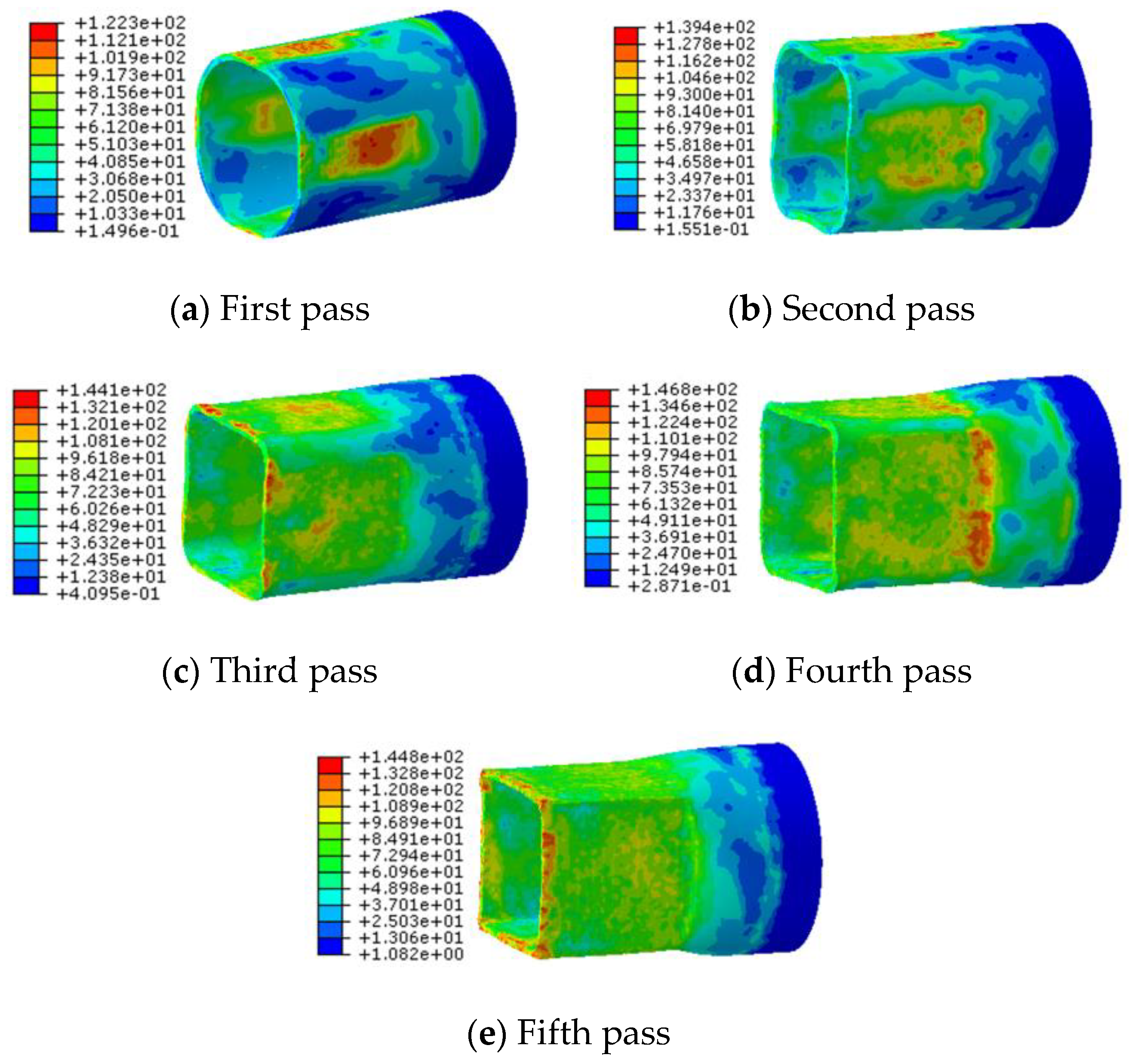
3.1.1. Equivalent von Mises Stress in Each Pass

Figure 5 shows the equivalent von Mises stress in the workpiece after each pass of the spinning process. Unlike conventional spinning, the stress in the workpiece did not present a layered distribution. This is because in conventional spinning, the roller always loads the workpiece, whereas in quadrilateral spinning, the workpiece is continuously loaded and unloaded throughout the spinning process. When the roller and the workpiece were separated, the external force exerted by the roller was temporarily removed, and elastic recovery occurred in a free state. When the workpiece was loaded by the roller once again, processing of the workpiece by the roller would result in an uneven distribution of elastic recovery and plastic deformation.
In areas of the workpiece deformed by the roller, relatively large stresses appeared. However, with the increasing number of passes, the von Mises stress would be more evenly distributed in the deformation zone due to the integrity of the workpiece. After the first, second and fourth passes, maximum stress occurred near the starting area of the forward pass where the workpiece was constrained by the undeformed zone. Therefore, fractures would mostly occur in this area, and this area would become a dangerous zone where defects were most likely to appear. Since the position at the free end of the roller was not processed during the previous backward pass, but was processed during the third and the fifth passes, stress at the free end would be larger during these two passes, and this area would become the second dangerous area zone where defects may appear.

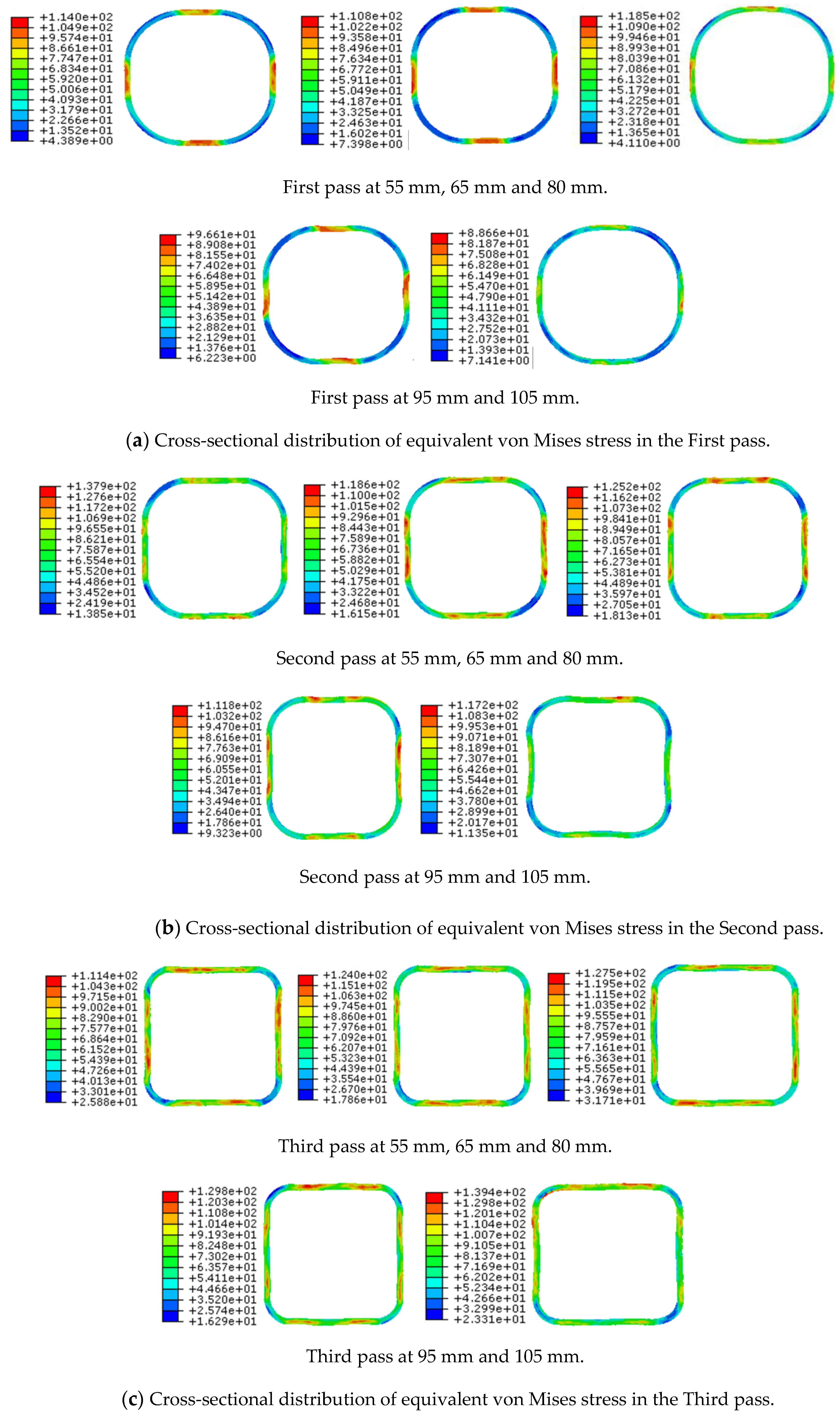
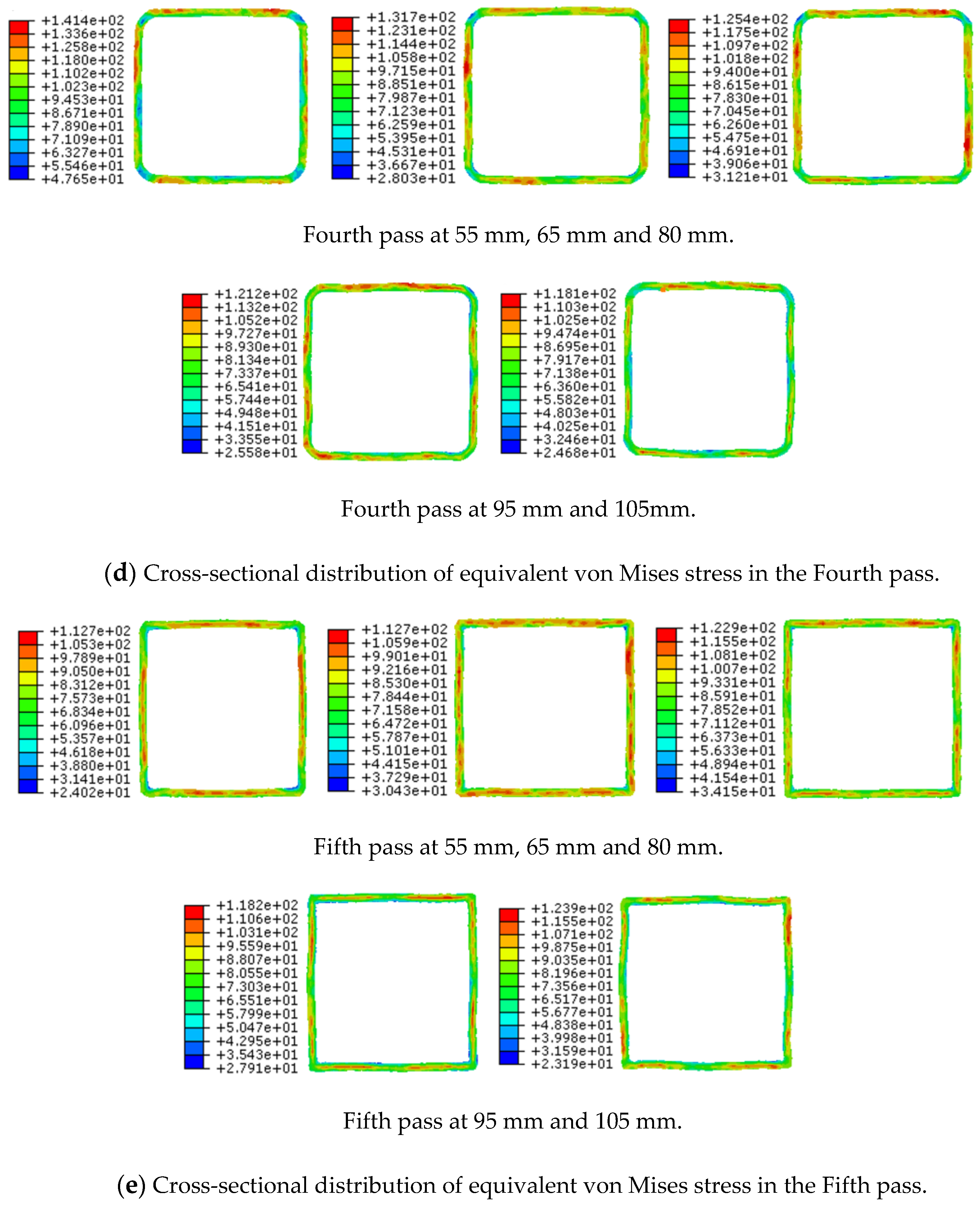
3.1.2. Cross-Section Distribution of Equivalent von Mises Stress after Each Pass

Figure 6 illustrates the distribution of equivalent von Mises stress in the cross-sectional area of the workpiece at a distance of 55 mm, 65 mm, 80 mm, 95 mm and 105 mm from the fixed end after each pass. After the second, third, fourth and fifth passes, the equivalent von Mises stresses of the workpiece were larger in the area of the workpiece gradually loaded by the roller and the area immediately before the roller unloading position. As the roller gradually loaded the workpiece, tensile stress was generated between the roller and the undeformed area in the material at an angle of 45°, as shown in Figure 4. Before the workpiece was unloaded, pressure existed between the roller and the undeformed area at an angle of 315°, as shown in Figure 4.
From the different positions of the cross-sectional profiles after each pass, the workpiece had a mostly regular profile from 65 mm to 95 mm. After the fourth and fifth passes, fluctuation in the cross-sectional could be observed near the free end (105 mm). As the number of passes increased, work hardening led to plasticity, and the fluidity of the material decreased. In addition, certain parameters, such as the radial feed of each pass and the feed rate in the axial direction, may be larger and the free end of the workpiece may exhibit strong elastic behavior due to the lack of a constraint. The material was not fully deformed by the spinning force, leading to low plastic stability and fluctuation of the profile near the free end.

3.2. Analysis of Strain Distribution

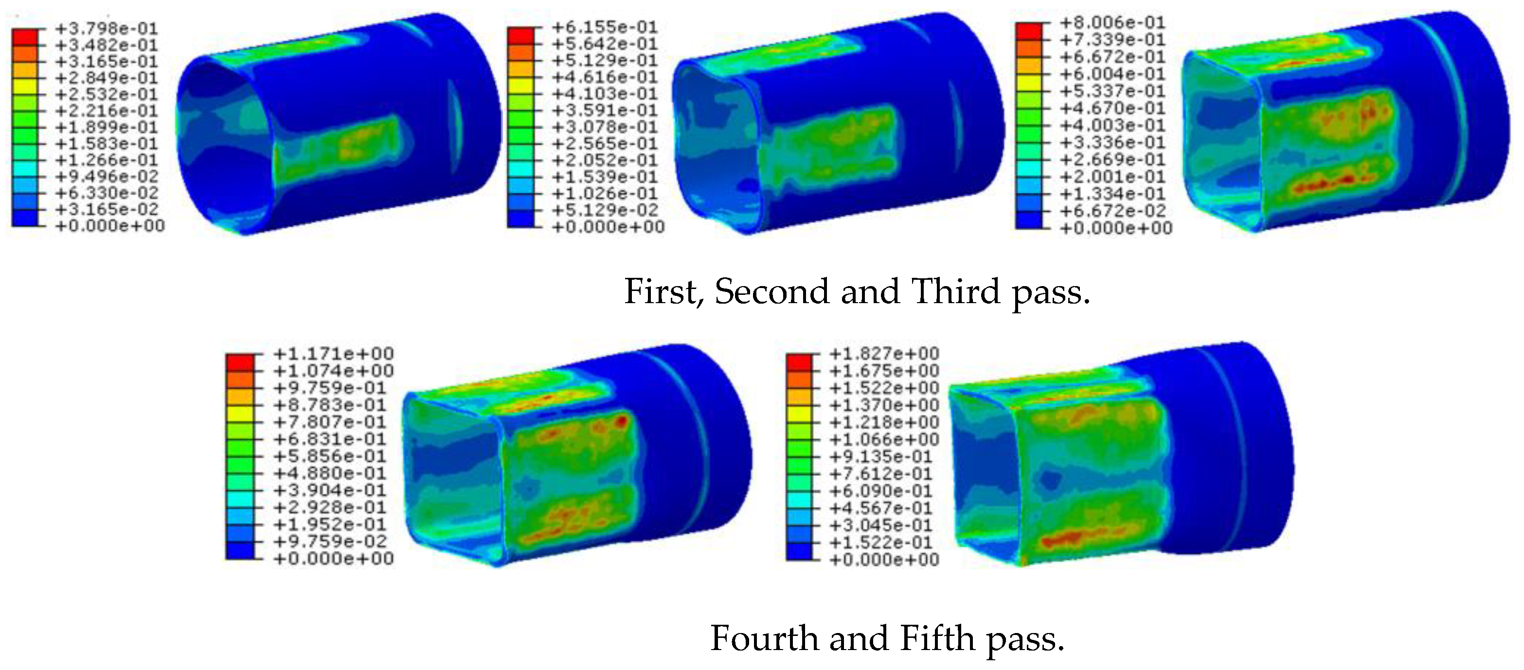
3.2.1. Equivalent Plastic Strain

Figure 7 shows the distribution of equivalent plastic strain in the workpiece after spinning in each pass. After several passes, strains in the workpiece were larger in the area gradually loaded by the roller and the area immediately before the workpiece was unloaded, which was consistent with the cross-sectional stress analysis. In the area gradually loaded by the roller, the material between the roller and undeformed area at an angle of 45° was pulled in tension, resulting in tensile strain in this area. Before the workpiece was unloaded, the material between the roller and undeformed area at an angle of 315° was compressed, resulting in compressive strain in this area.

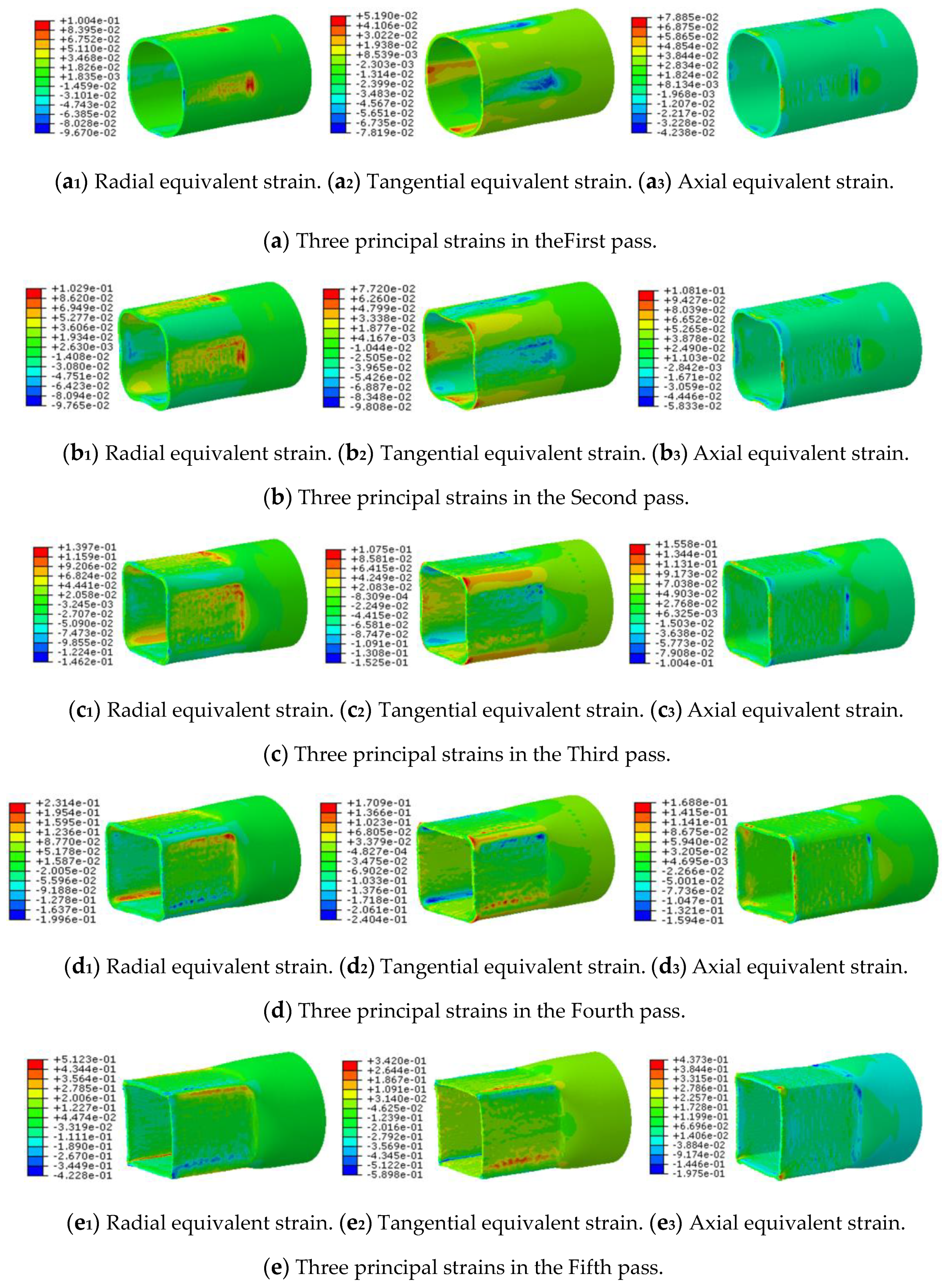
3.2.2. Principal Strains

Figure 8 shows the distribution of the three principal strains in the workpiece for each pass. The radial tensile strains in the first, second and third passes were larger in the area where the forward pass began. Tensile strain was generated because of the clamp constraint and the radial feed of the roller in the area. An overall trend of radial strain can be clearly observed in the fourth and fifth passes. In the area gradually loaded by the roller, compressive strain in the workpiece was presented in the radial direction because the material in this area was compressed in the radial direction by the movement of the roller relative to the workpiece. In the area immediately before the position at which the workpiece was unloaded, tensile strain was generated in the radial direction by the movement of the roller relative to the workpiece.
With the increasing number of passes, tangential tensile strain was produced in the corners and in the area where the workpiece was gradually loaded. During the spinning process, these two areas were stretched in the tangential direction by the roller. Compressive strain was generated in the area before the position of roller unloading because the material was compressed by the roller, and the material undeformed at corners.
Overall, the workpiece presented tensile stress in the axial direction. However, compressive strain appeared in the area where the forward pass began because the back of the roller restricted the flow of metal at the beginning of the forward pass, and material in this area was compressed in the axial direction. During the backward pass, material in this area was clearly compressed by the roller.

4. Analysis of Spinning Quality

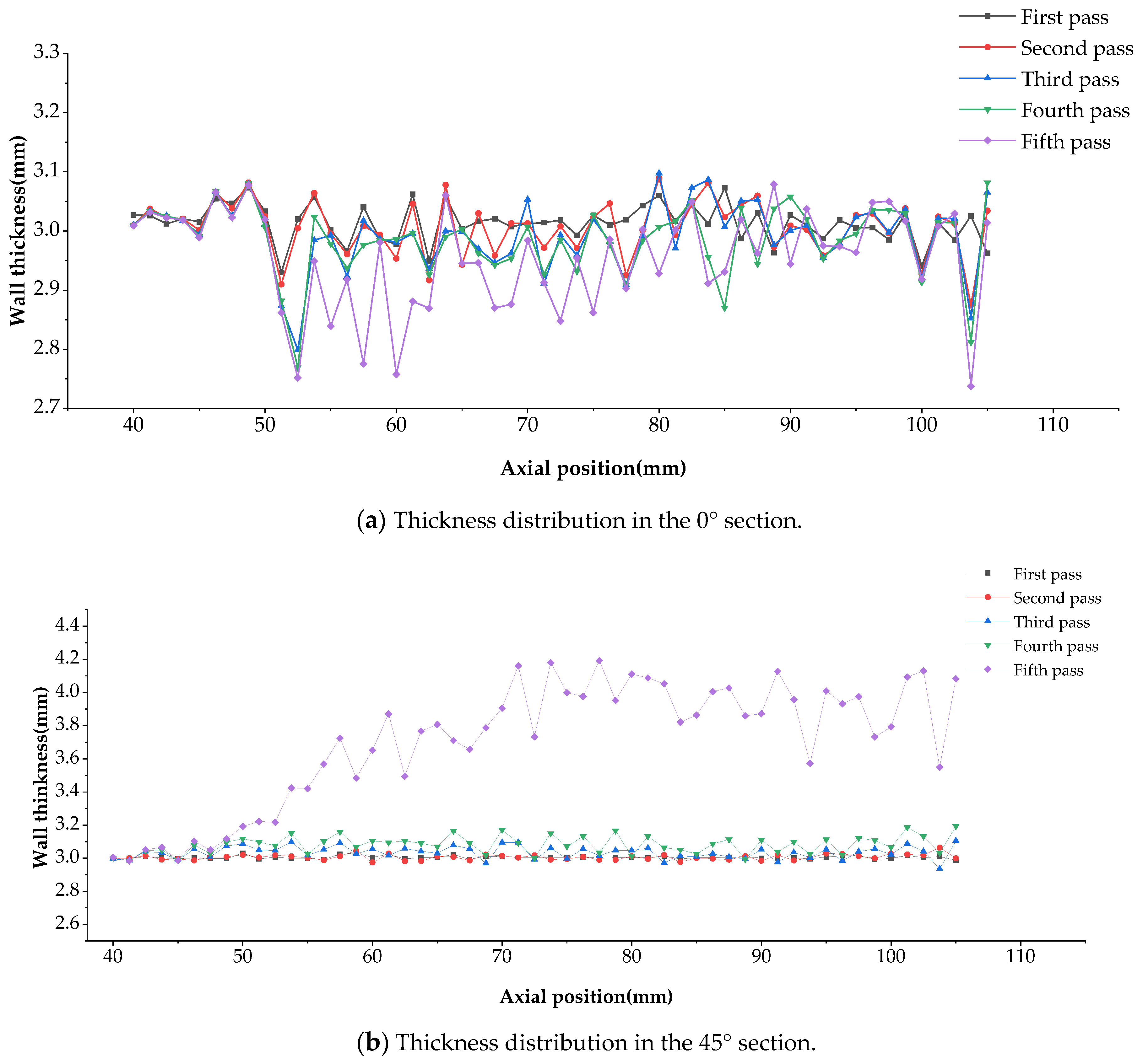
4.1. Thickness Distribution (0°, 45°)

Figure 9 shows the thickness distribution of the workpiece at 0° and 45° along the axial direction. In general, thinning and thickening trends in the forward and backward passes, respectively, were not obvious in the 0° section. In the spinning process, the roller and the workpiece contacted and separated continuously, and the contact time between the workpiece and the roller was very short, which is different from conventional spinning. In conventional spinning, stable axial tension in the forward pass and stable axial pressure in the backward pass are generated, which can make workpiece thinning or thickening obvious. Meanwhile, to reduce the simulation time, the axial feed rate was set to 2 mm/r. This parameter may need to be further reduced to obtain a constant thickness distribution using the proposed method.
In the 45° section, the overall wall thickness showed an increasing trend. In the first two passes, the section was compressed by the tangential force of the roller, but the thickening effect was not obvious due to the short contact time. In the third and fourth passes, the contact time between the roller and the workpiece was prolonged. The 45° section joined the two surfaces (the newly processed and the previously processed surfaces). In the second half loading stage of the processed surface, the roller compressed the 45° section in the tangential direction. The roller restricted metal flow in the tangential direction on the newly processed surface. They all caused the thickness of the 45° section to increase. Especially in the fifth pass, the processing of the two surfaces would be very close to the corner, and both would have a thickening effect, so the thickening was obvious in this pass.

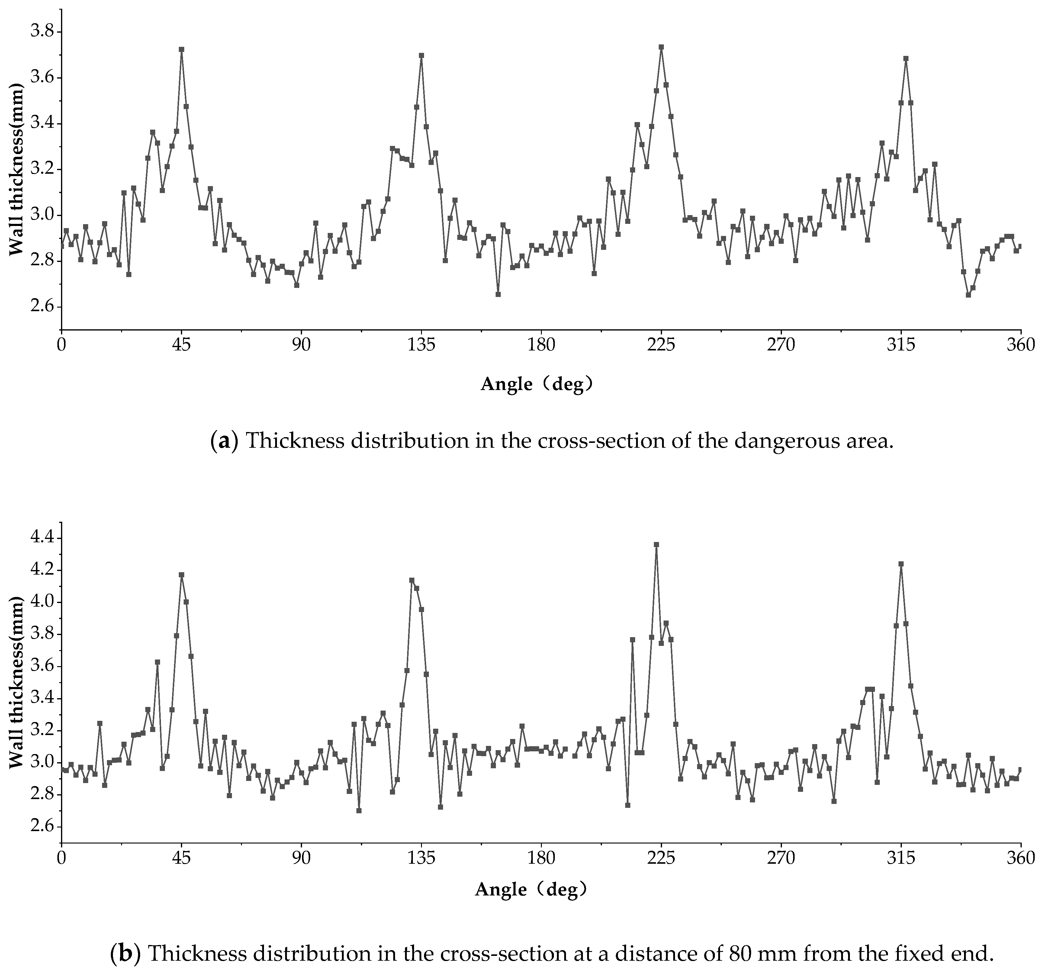
4.2. Thickness Distribution of the Dangerous Section and the Stable Section

As seen in Figure 9, the dangerous section prone to rupture of the workpiece was located at a distance of 52.5 mm away from the fixed end. The wall thickness distribution in this section was investigated. Figure 10a shows the wall thickness distribution along the tangential direction of this section. The angles of 0°, 90°, 180° and 270° correspond to the center of a side wall, and the angles of 45°, 135°, 225° and 315° correspond to the corners. Thinning and thickening can be clearly observed at the center of the sidewalls and in the corner, respectively, because the material in the center of the workpiece flowed continuously to the corners throughout the spinning process. In the dangerous section, the thinning rate was less than 10%, which was within the acceptable range.
The cross-section at a distance of 80 mm away from the fixed end represents the midpoint of each pass, and the spinning conditions were relatively stable here. Figure 10b shows the wall thickness distribution along the tangential direction. The angles of 0°, 90°, 180° and 270° correspond to the center of the sidewall, and the angles of 45°, 135°, 225° and 315° correspond to the corners. The area in the center of the sidewall was thinning. However, the thickness of the wall clearly increased at the corners. The thinning rate in the 80mm cross-section was less than 10%, which was within the acceptable range.

5. Conclusions

This study aimed to develop a new kind of high-efficiency, non-circular spinning method. This paper presented the derivation of the roller trajectory, a simulation of the novel non-circular spinning process and analysis of the simulation result. The main conclusions can be summarized as follows:
  • With this new non-circular spinning method, the rotation speed of the workpiece can be set to 600 rpm, thereby improving the efficiency of the spinning process by around 2.5 times compared with other non-circular spinning methods, in which the rotational speed of the workpiece is typically between 60–240 rpm. The thinning rate was below 10%, indicating that the surface quality of the formed workpiece was acceptable;
  • The trajectory equation of the roller was derived, which provided a theoretical basis for future experiments using this new type of metal spinning;
  • The results showed that the equivalent von Mises stress in the starting area of the forward pass was relatively large, and this area may become the first dangerous area during the process. Large stresses were also observed near the free end, which represents the second dangerous area;
  • The simulation results showed that the equivalent plastic strain distribution on each side of the quadrilateral workpiece was relatively consistent during the spinning process. Maximum strain occurred in the area of the workpiece gradually loaded by the roller and the area of the workpiece immediately before the unloading position.

Author Contributions

P.G., B.W. and X.Z. conceived the conceptualization; J.L. and X.O. designed the experiments; C.L. and X.L. performed the experiments; F.H. and Q.L. analyzed the data; O.X. wrote the paper. All authors have read and agreed to the published version of the manuscript.

Funding

This research was funded by the Higher Education Research Project of Jilin Province (No. JGJX2020D8) and the Science and Technology Development Project of Jilin Province (No. 20190302038G X).

Conflicts of Interest

The authors declare no conflict of interest.

References

  1. Zhan, T. Spinning Forming Technology; Chemical Industry Press: Beijing, China, 2019; pp. 8–29. [Google Scholar]
  2. Amano, T.; Tamura, K. The study of an elliptical cone spinning by the trial equipment. In Proceedings of the Third International Conference on Rotary Metalworking Processes, Kyoto, Japan, 8–10 September1984; pp. 213–224. [Google Scholar]
  3. Gao, X.C.; Kang, D.C.; Meng, X.F.; Wu, H.J. Experimental research on a new technology-ellipse spinning. J. Mater. Process. Technol. 1999, 94, 197–200. [Google Scholar] [CrossRef]
  4. Cheng, Q.M.; Kang, D.C. The study of elliptic spinning technique. J. Plast. Eng. 1997, 4, 56–59. [Google Scholar]
  5. Xia, Q.X.; Lai, Z.Y.; Zhan, X.X.; Cheng, X.Q. Research on spinning method of hollow part with triangle arc-type Cross section based on profiling driving. Steel Res. Int. 2010, 81, 994–998. [Google Scholar]
  6. Wu, X.Y. Numerical Simulation and Experimental Research of the Hollow Part with Four Arc-Typed Cross-Section. Master’s Thesis, South China University of Technology, Guangzhou, China, 2010. [Google Scholar]
  7. Shimizu, I. Asymmetric forming of aluminum sheets by synchronous spinning. J. Mater. Process. Technol. 2010, 210, 585–592. [Google Scholar] [CrossRef]
  8. Sugita, Y.; Arai, H. Development of synchronous multipath metal-spinning method for forming non-axisymmetric shapes. Trans. Jpn. Soc. Mech. Eng. 2012, 78, 274–282. [Google Scholar]
  9. Sugita, Y.; Arai, H. Formability in synchronous multipass spinning using simple pass set. J. Mater. Process. Technol. 2015, 217, 336–344. [Google Scholar] [CrossRef]
  10. Arai, H.; Kanazawa, T. Synchronous multi pass spinning of oblique-bottom shape. J. Mater. Process. Technol. 2018, 260, 66–76. [Google Scholar] [CrossRef]
  11. Arai, H. Robotic metal spinning—Forming asymmetric products using force control. In Proceedings of the 2005 IEEE International Conference on Robotics and Automation, Barcelona, Spain, 18–22 April 2005; pp. 2702–2707. [Google Scholar]
  12. Awiszus, B.; Meyer, F. Metal spinning of non-circular hollow parts. In Proceedings of the 8th International Conference on Technology of Plasticity, Verona, Italy, 9–13 October 2005; pp. 353–355. [Google Scholar]
  13. Arai, H. Force-controlled metal spinning machine using linear motors. In Proceedings of the 2006 IEEE International Conference on Robotics and Automation, Orlando, FL, USA, 15–19 May 2006; pp. 4031–4036. [Google Scholar]
  14. Liu, X.L.; Liu, X.H. Plain motion of hypocycloid. J. Changsha Railw. Univ. 2016, 16, 75–79. [Google Scholar]
  15. Xia, H.Y.; Dai, J.P.; Zhao, C. The trajectory property analysis of inner cycloid. Mech. Electr. Eng. Technol. 2017, 1, 25–30. [Google Scholar]
Figure 1. Finite element model of the novel non-circular spinning method.
Applsci 10 08588 g001
Figure 2. Schematic drawing of a hypocycloid.
Applsci 10 08588 g002
Figure 3. Schematic illustration of the roller trajectories obtained using the non-circular spinning method based on hypocycloid theory.
Applsci 10 08588 g003
Figure 4. Schematic drawing of the non-circular spinning process stages.
Applsci 10 08588 g004
Figure 5. Distribution of equivalent von Mises stress after each pass of the non-circular spinning process.
Applsci 10 08588 g005
Figure 6. Cross-sectional distribution of equivalent von Mises stress for each pass of the non-circular spinning process.
Applsci 10 08588 g006aApplsci 10 08588 g006b
Figure 7. Equivalent strain in the workpiece for each pass of the non-circular spinning process.
Applsci 10 08588 g007
Figure 8. Three principal strains in the workpiece for each pass of the non-circular spinning process.
Applsci 10 08588 g008
Figure 9. Thickness distribution in the 0° and 45° sections.
Applsci 10 08588 g009
Figure 10. Thickness distribution in a typical cross-section of a workpiece.
Applsci 10 08588 g010
Table 1. Mechanical properties of the 6061 aluminum alloy.
Mechanical PropertiesValue
Yield Strength62.05 MPa
Ultimate Strength151.68 MPa
Young’s Modulus69,000 MPa
Poisson’s Ratio0.3
Table 2. Process parameters selected for the simulations.
ParametersValue
Radial feed of each pass2 mm, 2 mm, 2 mm, 1.5 mm, 1.2 mm
Feed rate in the axial direction2 mm/r
Roundness radius of the rollers6 mm
Rotation speed of the principal axis of the roller1200 r/min
Rotation speed of the principal axis of the workpiece600 r/min
Diameter of the roller100 mm
Distance between the center of the roller and the center of the roller’s principal axis100 mm
Publisher’s Note: MDPI stays neutral with regard to jurisdictional claims in published maps and institutional affiliations.

