Phase Change Materials and Their Benefits in ETICS


Abstract
1. Introduction
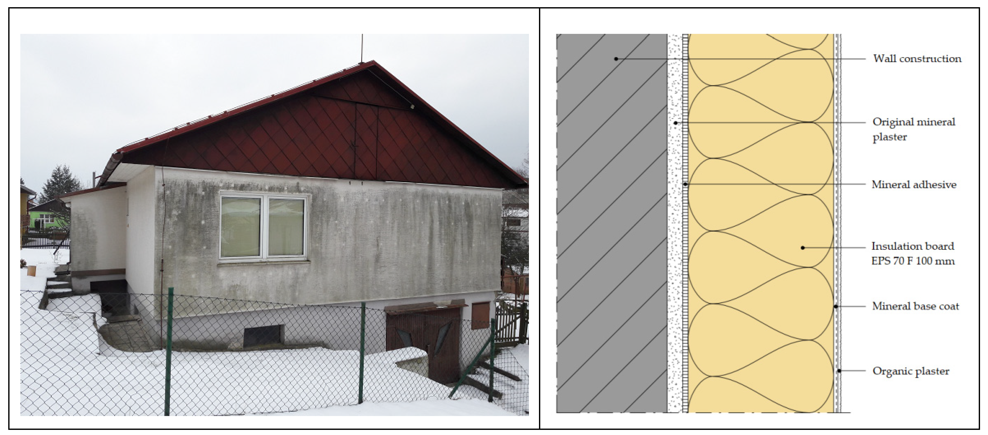
1.1. Heat Storage of ETICS
- ETICS overheating due to solar radiation, which mechanically burdens the thermal insulation system [16].
1.2. Purpose and Impact of Biocides
1.3. Biotic Attack on ETICS Facade:
1.4. ETICS Temperature Change Due to the Influence of Sunlight
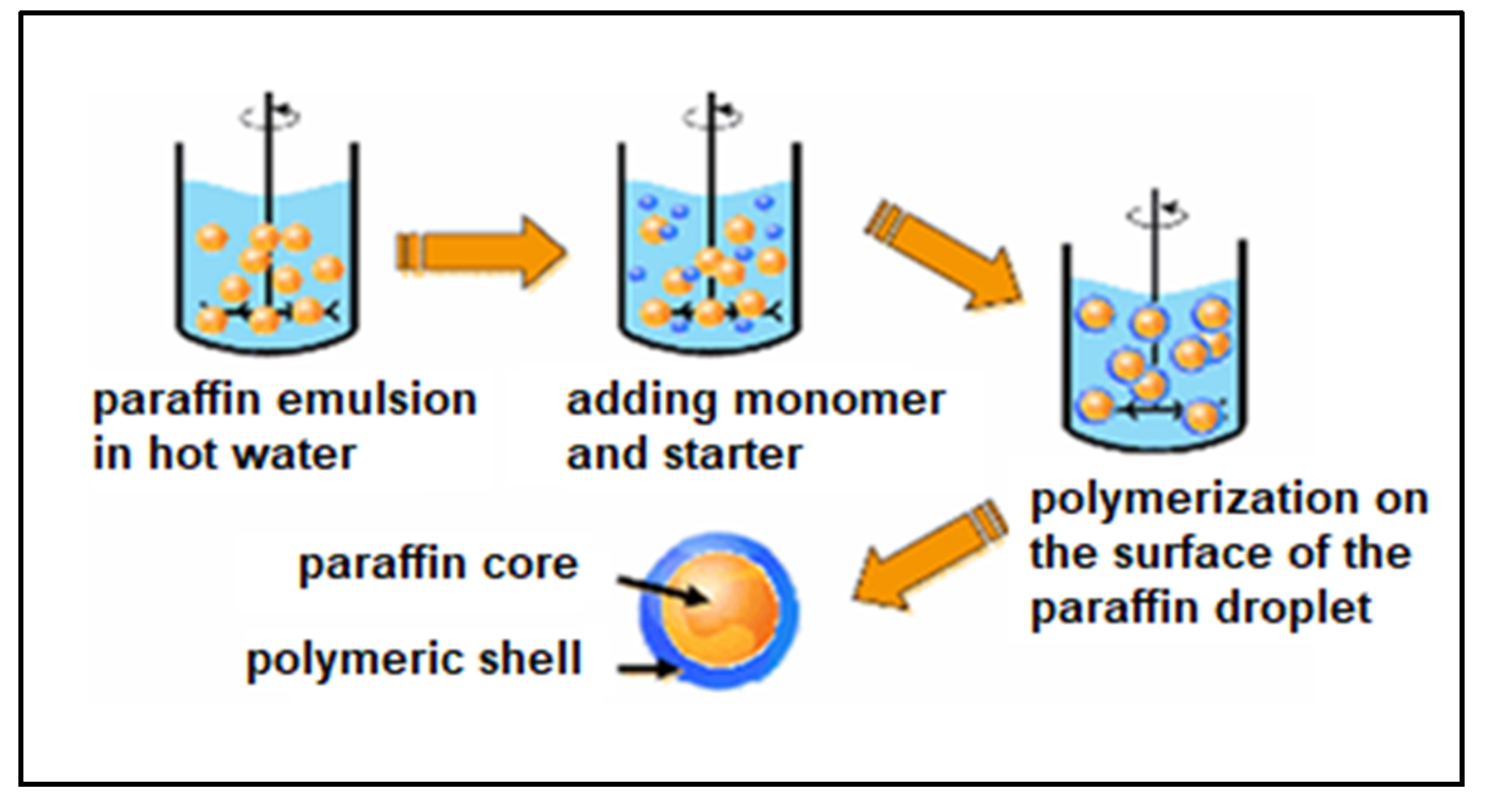
1.5. PCM Materials
2. Materials and Methods
2.1. Constituent Materials
2.1.1. Ethylene-vinyl Acetate Copolymer
2.1.2. Cement
2.1.3. Hydrated Lime
2.1.4. Calcium Carbonate
2.1.5. Quartz Sand
2.1.6. Cellulose Ether
2.1.7. Rheological Additive Sepiolite
2.1.8. Hydrophobic Agents
2.1.9. Reducing Agent Cr6+
2.1.10. Fly Ash
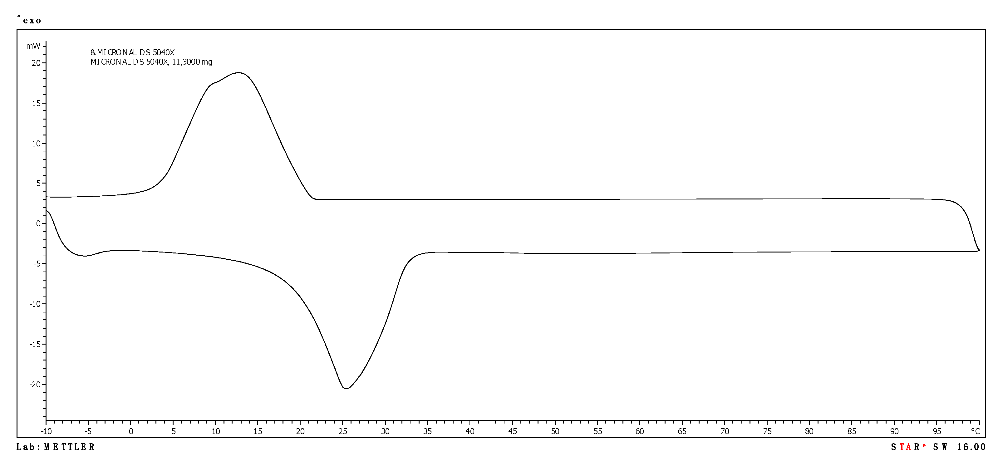
2.1.11. PCM
- Micronal DS 5040 X manufactured by Microtek (USA)
- Nextek 6D manufactured by (USA)
- Nextek 18D manufactured by (USA)
2.1.12. Polypropylene Fibres 4 mm
2.2. Verified Mix Designs
2.3. Test Methodology
3. Results and Discussion
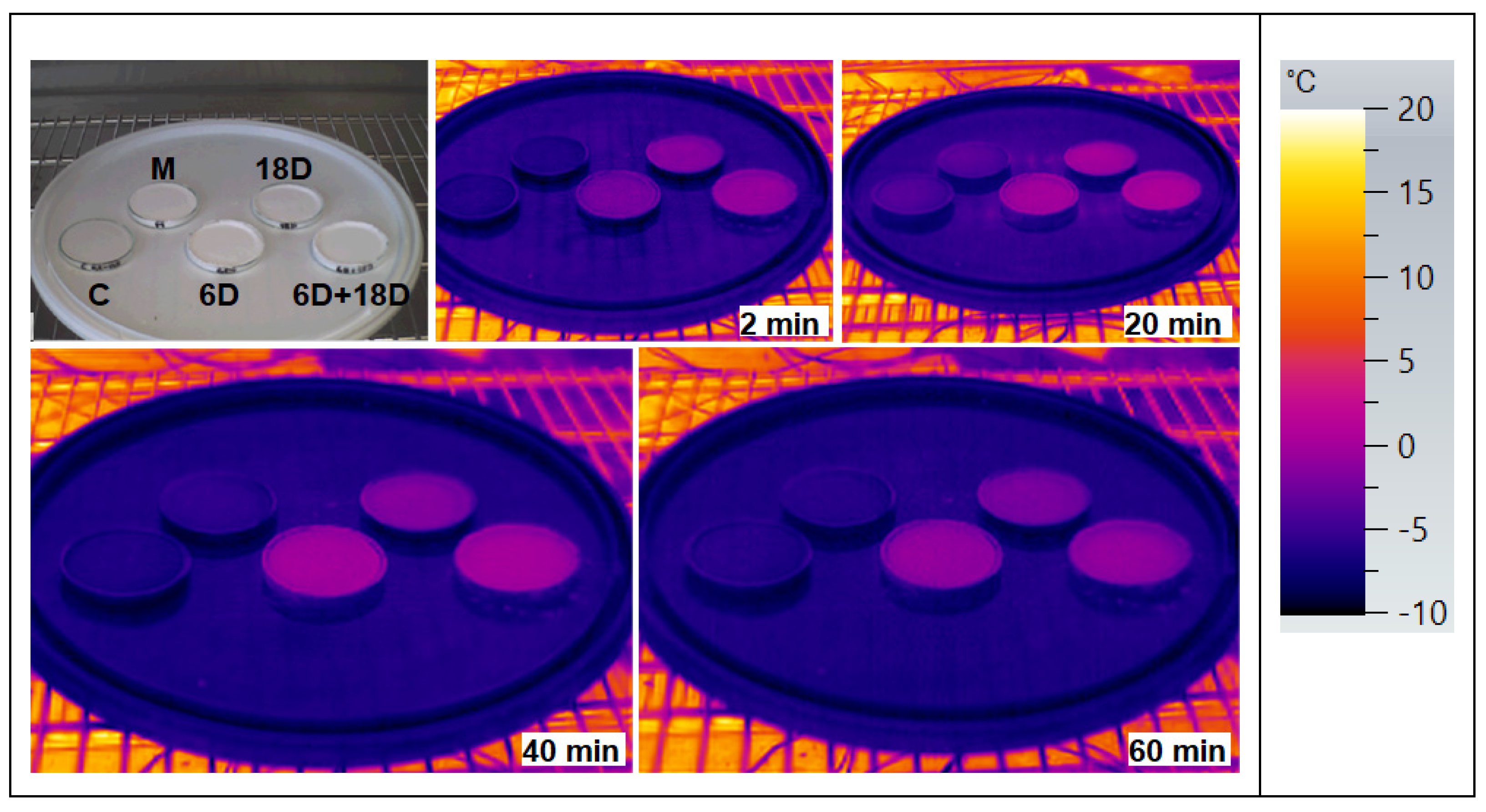
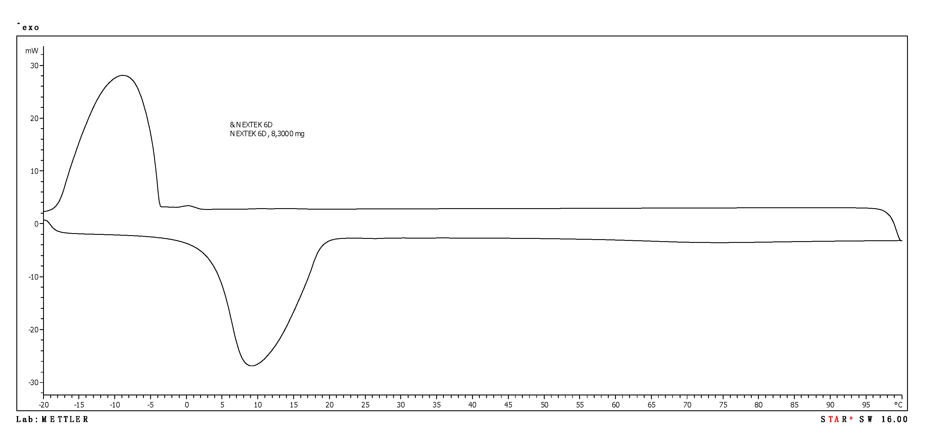
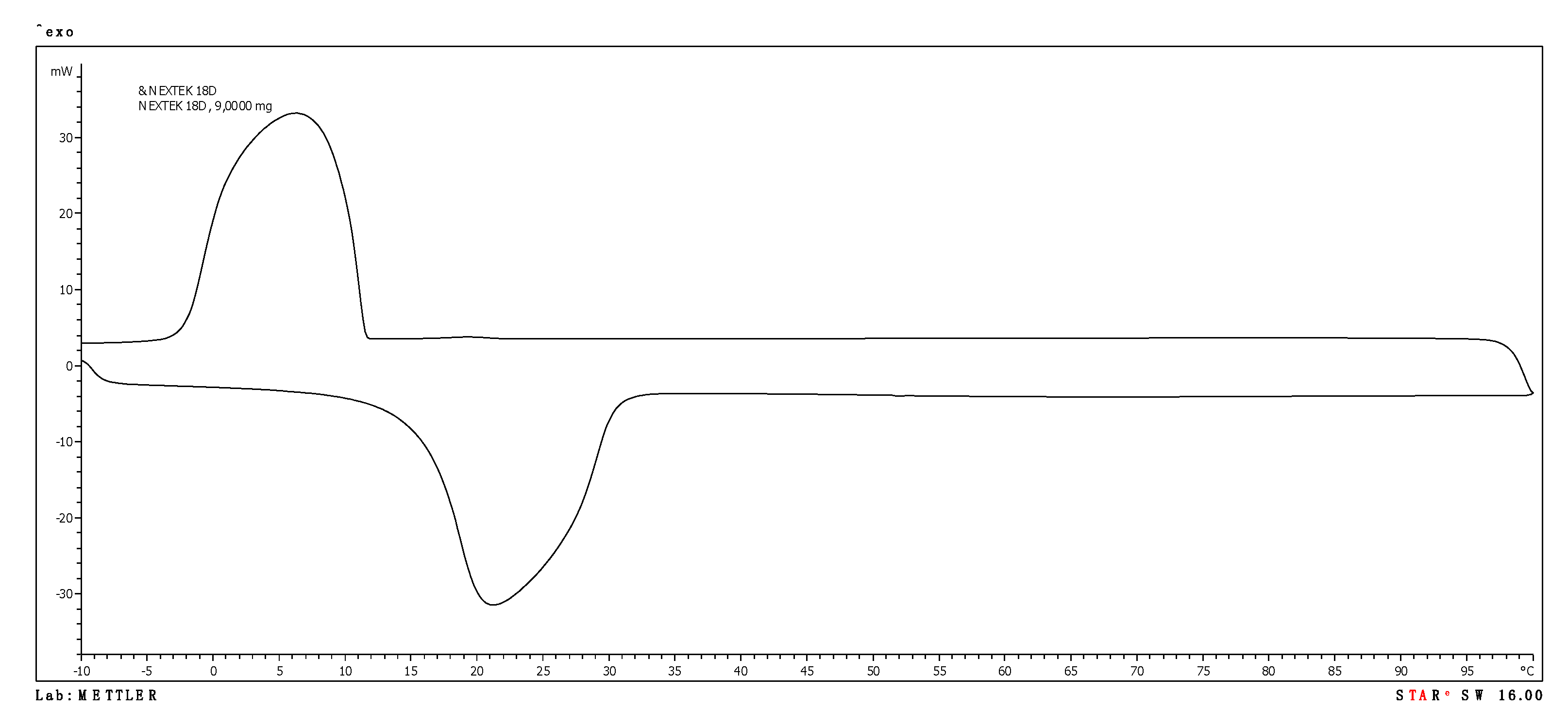
3.1. PCM Products Tested
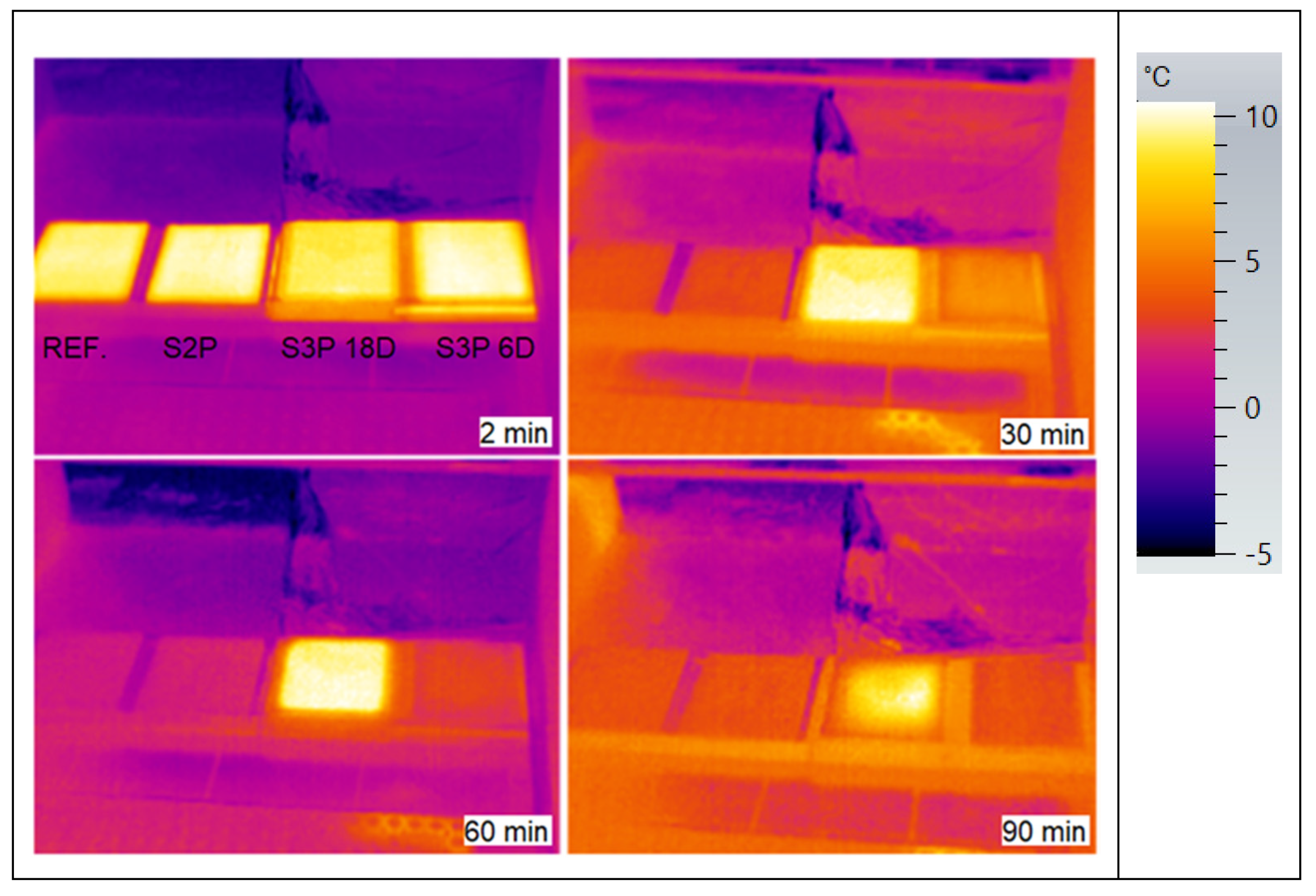
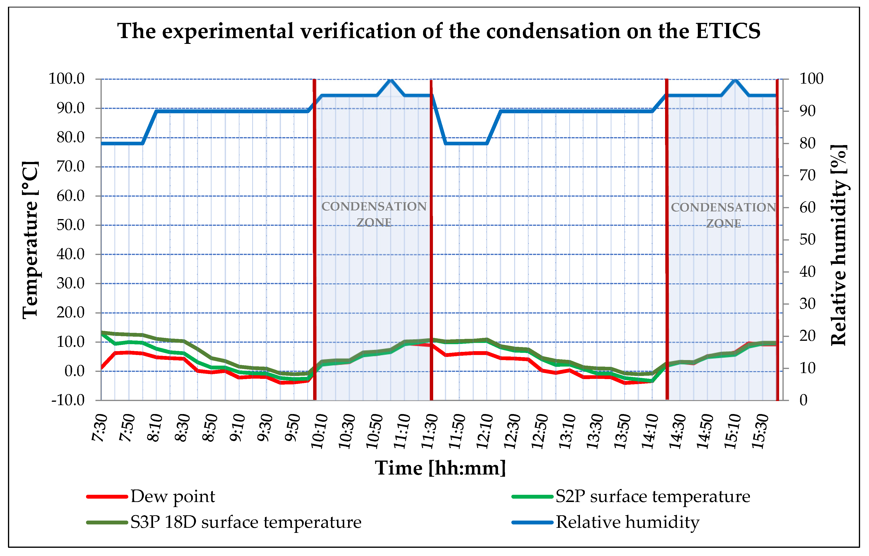
3.2. ETICS Base Coat with PCM Test on Insulator
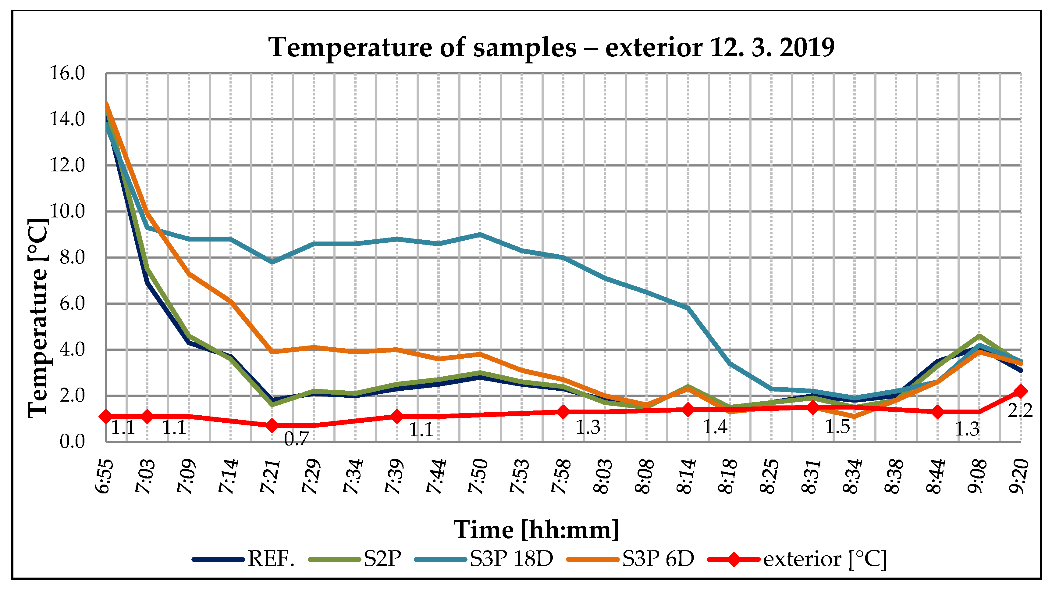
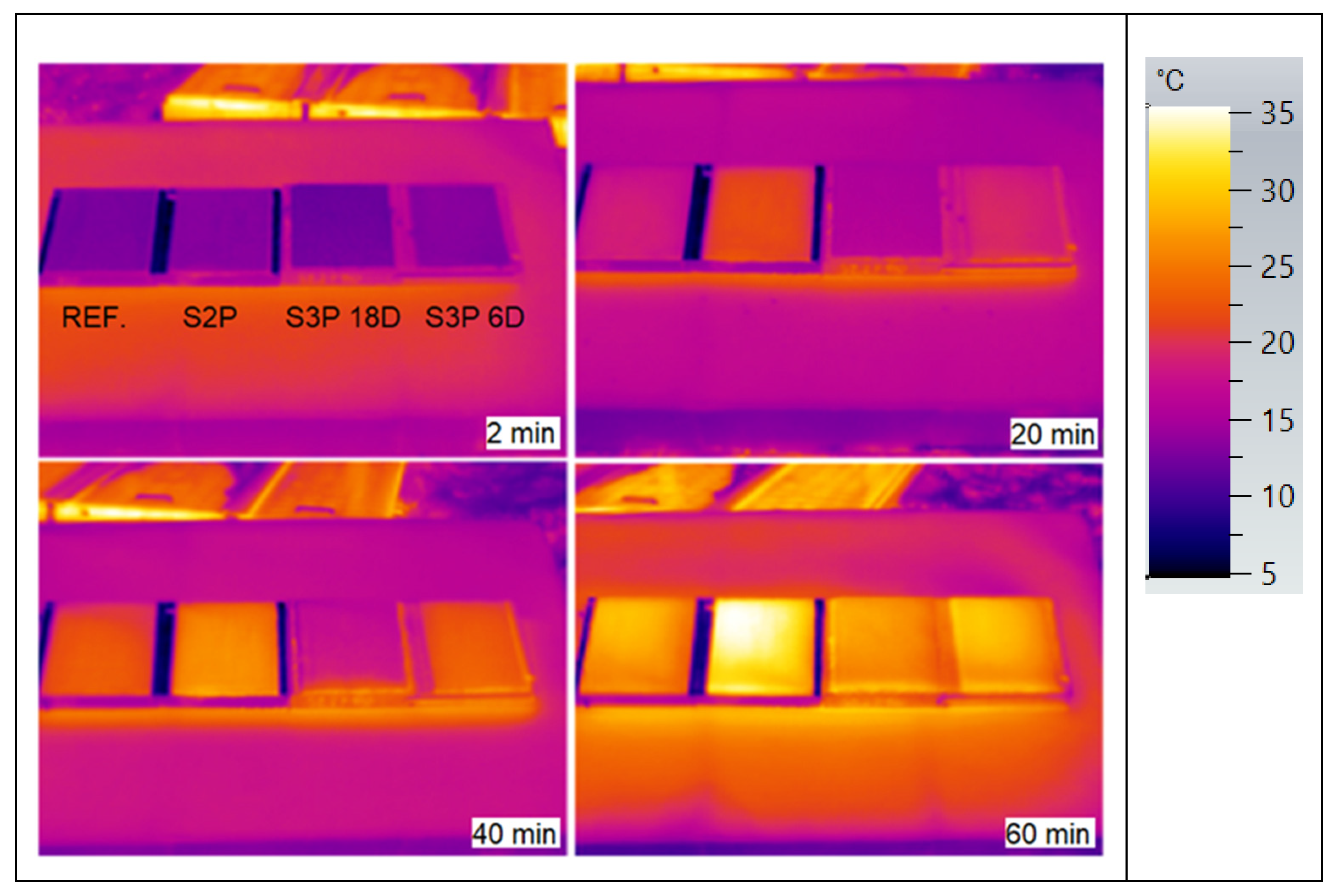
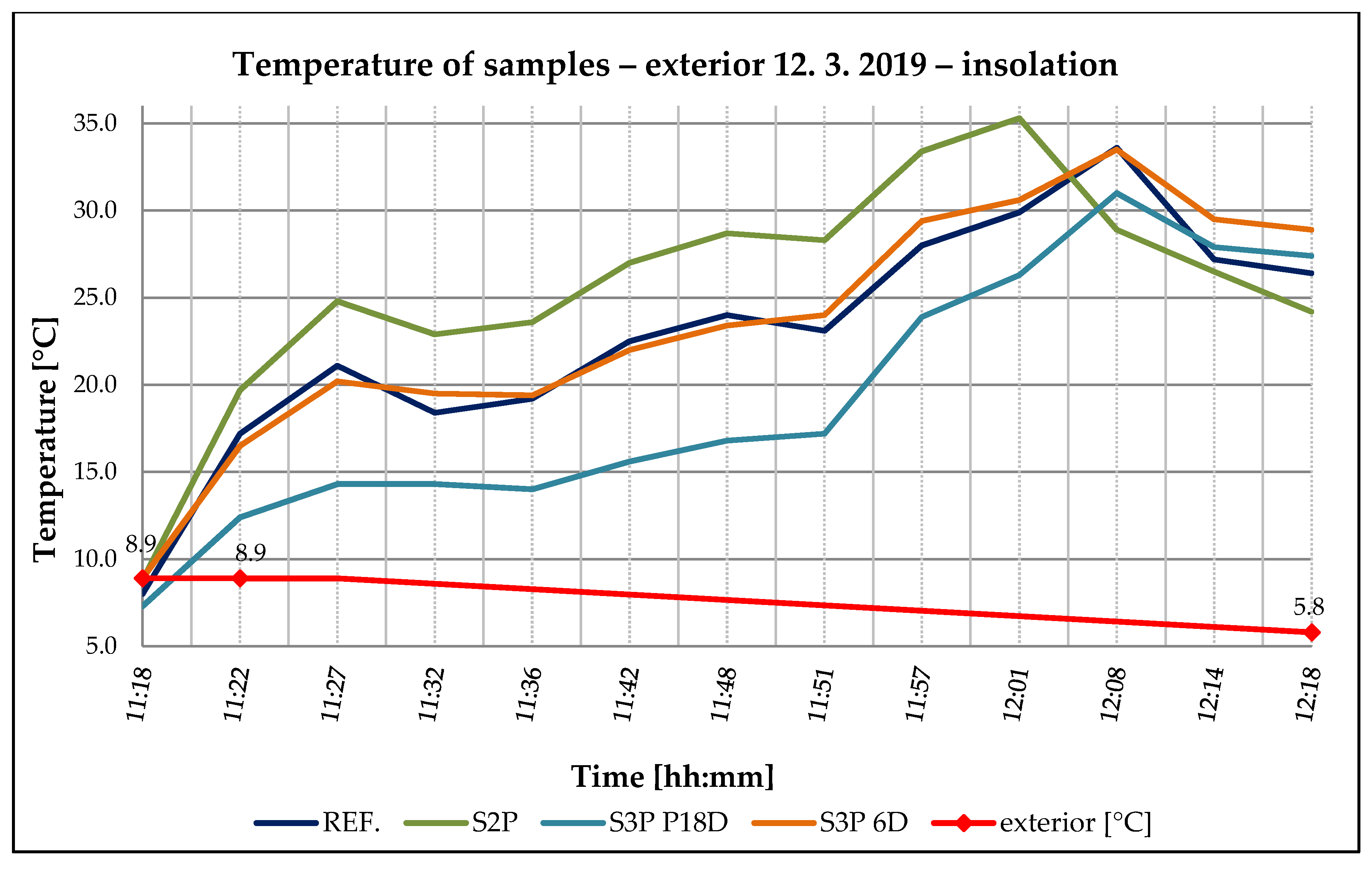
3.3. ETICS Base Coat Test with PCM on Insulator—Solar Effect
4. Conclusions
Author Contributions
Funding
Acknowledgments
Conflicts of Interest
References
- Zach, J.; Žižková, N.; Novák, V.; Hroudová, J.; Sokola, L. Využití ETICS Pro Obnovy Obvodových Plášťů Budov; Ing. Ladislav Pokorný—LITERA: Brno, Czech Republic, 2014; ISBN 978-80-214-4957-2. [Google Scholar]
- Stempel, E.U. Zateplení a rekonstrukce rodinného domu; Grada, a.s.: Praha, Czech Republic, 2014; ISBN 978-80-247-4808-5. [Google Scholar]
- Blaich, J. Poruchy Staveb; Jaga Group, v.o.s.: Bratislava, Slovakia, 2001; ISBN 80-88905-50. [Google Scholar]
- Raschle, P.; Büchli, R. Algen und Pilze an Fassaden, Ursachen und Vermeidung; Fraunhofer IRB Verlag: Stuttgart, Germany, 2004; ISBN 3-8167-6426-6. [Google Scholar]
- Karsten, U.; Schumann, R.; Häubner, N.; Friedl, T. Aeoroterrestrisch microalgen. Lebensraum fassade. Biol. Unserer Zeit 2005, 35, 20–30. [Google Scholar] [CrossRef]
- Künzel, H.M. Factors determining surface moisture on external walls. In Performance of Exrerior Envelopes of Whole Buildings X; ASHRAE: Clearwater Beach, FL, USA, 2007. [Google Scholar]
- Künzel, H.M.; Sedlbauer, K. Algen und Wärmedämm-Verbundsystemen; IBP-Mitteilung: Stuttgart, Germany, 2001. [Google Scholar]
- Künzel, H.M.; Sedlbauer, K. Biological growth on stucco. In Performance of Exrerior Envelopes of Whole Buildings VIII; ASHRAE: Clearwater Beach, FL, USA, 2001. [Google Scholar]
- Sedlbauer, K.; Krus, M. Schimmelpilzbildung auf WDVS infolge “Baufehlern“. IBP-Mitteilung: Stuttgart, Germany, 2001; pp. 43–45. [Google Scholar]
- Sedlbauer, K.; Krus, M.; Hofbauer, W.K.; Breuer, K.; Fitz, C. Neue erkentnisse zum mikrobiellen Bewuchs auf Aussenoberflächen. Wärme Kälte Schall Brandschutz 2006, 56, 10–18. [Google Scholar]
- Hofbauer, W.K.; Breuer, K.; Fitz, C.; Sedlbauer, K. Algen, flechten, moose und farne auf fassaden. Bauphysik 2003, 25, 3–16. [Google Scholar] [CrossRef]
- Ortega-Calvo, J.J.; Hernandez-Marine, M.; Saiz-Jimenez, C. Biodeterioration of building materials by cyanobacteria and algae. Int. Biodeterior. 1991, 28, 165–185. [Google Scholar] [CrossRef]
- Viitanen, H.A.; Bjurman, J. Mould growth on wood at fluctuating humidity conditions. Mater. Org. 1995, 29, 27–46. [Google Scholar]
- Coppock, J.B.M.; Cookson, E.D. The effect of humidity on mould growth on constructional materials. J. Sci. Food Agric. 1951, 2, 534–537. [Google Scholar] [CrossRef]
- Nielsen, K.F.; Holm, G.; Uttrup, L.P. Mould growth on building materials under low water activities: Influence of humidity and temperature on fungal growth and secondary metabolism. Int. Biodeterior. Biodegrad. 2004, 54, 325–336, ISSN 0964-8305. [Google Scholar] [CrossRef]
- Vilín, R. Vliv nízké odrazivosti světla v tmavých odstínech sasádních barev a omítek na trhliny v podkladech s ETICS, izolant EPS. Available online: http://www.tip-basf.cz/vliv-nizke-odrazivosti-svetla-v-tmavych-odstinech-fasadnich-barev-a-omitek-na-trhliny-v-podkladech-s-etics-izolant-eps (accessed on 28 November 2020).
- Pikl, Z. Odolnost povrchů omítek na ETICS proti znečištění. Available online: https://www.dekpartner.cz/aktuality/detail/211 (accessed on 28 November 2020).
- Steuer, R. Studium vlastností materiálů vnějšího zateplení budov z hlediska snížení vlhkostní zátěže. Ph.D. Thesis, VUT Brno, Fakulta stavební, Ústav technologie stavebních hmot a dílců, Brno, Czech Republic, 2016. [Google Scholar]
- Shirakawa, M.L.; Beech, I.B.; Tapper, R.; Cincotto, M.A.; Gambale, W. The development of a metod to evaluate bioreceptivity of indoor mortar plastering to fungal growth. Int. Biodeterior. Biodegrad. 2003, 51, 83–92. [Google Scholar] [CrossRef]
- Shirakawa, M.L.; John, V.M.; Gaylarde, C.C.; Gaylarde, P.; Gambale, W. Mould and phototroph growth on masonry facades after repaiting. Mater. Struct. 2004, 37, 472–479. [Google Scholar] [CrossRef]
- Johansson, S.; Wadsö, L.; Sandin, K. Estimation of mould growth levels on rendered facades based on surface relative humidity and surface temperature measurements. Build. Environ. 2010, 45, 1153–1160. [Google Scholar] [CrossRef]
- David, J. Problematika Hodnocení Poruch a Vad Systémů ETICS. Master’s Thesis, VUT Brno, Fakulta Stavební, Ústav Stavebního Zkušebnictví, Brno, Czech Republic, 2016. [Google Scholar]
- Zhang, Y.; Zhou, G.; Lin, K.; Di, H. Application of latent heat thermal energy storage in buildings: State of the art and outlook. Build. Environ. 2007, 42, 2197–2209. [Google Scholar] [CrossRef]
- Casiday, R.; Frey, R. Phase Changes and Refrigeration: Thermochemistry of Heat Engines; University St. Louis: St. Louis, MO, USA, 2001; Available online: http://www.chemistry.wustl.edu/~edudev/LabTutorials/Thermochem/Fridge.html (accessed on 16 December 2016).
- Šebek, J. Studium pasivní stabilizace teploty kompozitních stavebních materiálů, Master’s Thesis, VUT Brno, Fakulta Chemická, Brno, Czech Republic, 2010. [Google Scholar]
- Zalba, B.; Marín, J.; Cabeza, L.; Mehling, H. Review on thermal energy storage with phase change: Materials, heat transfer analysis and applications. Appl. Therm. Eng. 2003, 23, 251–283. [Google Scholar] [CrossRef]
- Socaciu, L.; Plesa, A.; Unguresan, P.; Giurgiu, O. Review on phase chase materials for building applications. Leonardo Electron. J. Pract. Technol. 2014. ISSN 1583-1078. Available online: https://www.researchgate.net/publication/287305188_Review_on_phase_change_materials_for_building_applications?_sg=Ek8aPpGULMYtC2meoFfsjmJY4v5f1KTSuA6TQRO599aWEuhvGdJ9ue-QzsX5CL0wnSzBGfBhbw (accessed on 21 June 2018).
- Mehling, H.; Cabeza, F.L. Heat and Cold Storage with PCM, an up to Date Introduction into Basics and Applications.; Springer-Verlag: Berlin/Heidelberg, Germany, 2008; ISBN 978-3-540-68556-2. [Google Scholar]
- Zavoralová, P. Využití materiálů s fázovou přeměnou (PCM) ve stavebnictví. Master’s Thesis, České vysoké učení technické v Praze, Fakulta stavební, Katedra technických zařízení budov, Prague, Czech Republic, 2010. [Google Scholar]
- Memon, S.A. Phase change materials integrated in building walls: A stat of the art review. Renew. Sustain. Energy Rev. 2014, 31, 870–906. Available online: http://www.sciencedirect.com/science/article/pii/S1364032113008563 (accessed on 2 July 2014). [CrossRef]
- Whiffen, T.R.; Riffat, S.B. A review of PCM technology for thermal energy storage in the built environment: Part I. Int. J. Low Carbon Technol. Adv. 2013, 8, 147–158. Available online: http://ijlct.oxfordjournals.org/content/early/2012/05/30/ijlct.cts021 (accessed on 1 February 2020). [CrossRef]
- Soares, N.; Costa, J.J.; Gasper, A.R.; Santos, P. Review of passive PCM latent heat thermal energy storage systems towards buildings energy efficiency. Energy Build. 2013, 59, 82–103. Available online: http://www.sciencedirect.com/science/article/pii/S0378778813000157 (accessed on 1 February 2020). [CrossRef]


| Thermo-Physical Properties |
|---|
|
| Kinetic properties |
| Chemical properties |
|
| Environmental properties |
| Input Materials | REF. | S2 P | S3 P6D | S3 P18D |
|---|---|---|---|---|
| [%] | [%] | [%] | [%] | |
| Water | 21 | 21 | 40 | 40 |
| Ethylene-vinyl acetate copolymer | 1.800 | 1.800 | 2.100 | 2.100 |
| Cement CEM I 42.5 R | 22.000 | 16.000 | 20.000 | 20.000 |
| Hydrated lime CL 90-S | 1.800 | 1.800 | 1.800 | 1.800 |
| Calcium carbonate 0.2–0.5 mm | 65.899 | 55.917 | 21.500 | 21.500 |
| Quartz sand 0.2–0.8 mm | 8.000 | 8.000 | 10.000 | 10.000 |
| Cellulose ether-HPMC | 0.135 | 0.135 | 0.140 | 0.140 |
| Rheological additive sepiolite | 0.150 | 0.150 | 0.150 | 0.150 |
| Zinc stearate | 0.100 | 0.100 | 0.100 | 0.100 |
| Sodium oleate | 0.050 | 0.050 | 0.050 | 0.050 |
| Reducing agent Cr6+ | 0.066 | 0.048 | 0.060 | 0.060 |
| Fly ash Dětmarovice | 16.000 | 16.000 | 16.000 | |
| Nextek 6D | 28.000 | |||
| Nextek 18D | 28.000 | |||
| Polypropylene fibres 4 mm | 0.100 | 0.100 | ||
| SUM | 100.000 | 100.000 | 100.000 | 100.000 |
| Materials | Heating | Cooling | ||
|---|---|---|---|---|
| Tm | ∆Hm | Tc | ∆Hc | |
| [°C] | [J/g] | [°C] | [J/g] | |
| Micronal DS 5040 X | 24.79 | 56.71 | 13.46 | 77.98 |
| Nextek 6D | 8.51 | 166.53 | −7.89 | 160.69 |
| Nextek 18D | 20.52 | 165.83 | 7.12 | 184.07 |
Publisher’s Note: MDPI stays neutral with regard to jurisdictional claims in published maps and institutional affiliations. |
© 2020 by the authors. Licensee MDPI, Basel, Switzerland. This article is an open access article distributed under the terms and conditions of the Creative Commons Attribution (CC BY) license (http://creativecommons.org/licenses/by/4.0/).
Share and Cite
Sokola, L.; Žižková, N.; Novák, V.; Jakubík, A. Phase Change Materials and Their Benefits in ETICS. Appl. Sci. 2020, 10, 8549. https://doi.org/10.3390/app10238549
Sokola L, Žižková N, Novák V, Jakubík A. Phase Change Materials and Their Benefits in ETICS. Applied Sciences. 2020; 10(23):8549. https://doi.org/10.3390/app10238549
Chicago/Turabian StyleSokola, Lubomír, Nikol Žižková, Vítězslav Novák, and Aleš Jakubík. 2020. "Phase Change Materials and Their Benefits in ETICS" Applied Sciences 10, no. 23: 8549. https://doi.org/10.3390/app10238549
APA StyleSokola, L., Žižková, N., Novák, V., & Jakubík, A. (2020). Phase Change Materials and Their Benefits in ETICS. Applied Sciences, 10(23), 8549. https://doi.org/10.3390/app10238549