Review

Properties of the Fine Granular Area and Postulated Models for Its Formation during Very High Cycle Fatigue—A Review

by
Jan Patrick Sippel
* and
Eberhard Kerscher
Materials Testing (AWP), Technische Universität Kaiserslautern (TUK), D-67663 Kaiserslautern, Germany
*
Author to whom correspondence should be addressed.
Appl. Sci. 2020, 10(23), 8475; https://doi.org/10.3390/app10238475
Submission received: 2 November 2020 / Revised: 25 November 2020 / Accepted: 26 November 2020 / Published: 27 November 2020
(This article belongs to the Special Issue Advances in Very-High-Cycle Fatigue)

Abstract

:
Understanding the mechanisms leading to very high cycle fatigue is necessary to make predictions about the behavior under various conditions and to ensure safe design over the whole lifetime of high-performance components. It is further vital for the development of possible measures to increase the very high cycle fatigue strength. This review therefore intends to give an overview of the properties of the fine granular area that have been observed so far. Furthermore, the existing models to describe the early crack initiation and crack growth within the very high cycle fatigue regime are outlined and the models are evaluated on the basis of the identified fine granular area properties. The aim is to provide an overview of the models that can already be considered refuted and to specify the respective open questions regarding the other individual models.

1. Introduction

The fatigue failure beyond the traditional fatigue limit above 107 cycles is called very high cycle fatigue (VHCF) [1], ultra-high cycle fatigue [2], ultralong life fatigue [3], as well as very high fatigue life regime or gigacycle regime [4]. This fatigue regime is constantly gaining attention because of the efforts in lightweight construction and the resulting use of highly stressed components, as well as the higher traveling speed combined with the demand of high service life. Many components and parts such as automotive engines, rotors of helicopters, turbines, as well as wheels and axles of high-speed trains are subjected to cyclic loadings with cycles exceeding the traditional fatigue limit of 107 cycles by far [5,6,7]. To ensure safe design of those components, the characteristic fatigue mechanism in the VHCF-regime, which differs from the low cycle fatigue (LCF) and high cycle fatigue (HCF) must be understood. While internal crack initiation with the characteristic fish-eye morphology named by Sakai et al. [8] can be observed in the HCF-regime a unique change in microstructure in the direct vicinity of the crack-initiating defect is observed in VHCF-regime. This characteristic microstructural feature in the VHCF-regime was designated “optically dark area” (ODA) [9], “granular bright facet” (GBF) [10], “rough granular area” (RGA) [11], or “fine granular area” (FGA) [12] depending on the observation method. However, all four designations describe the identical fracture area that differs from the original structure. In several investigations [12,13,14,15,16] of the fracture surface area it could be shown by means of selected area electron diffraction (SAD) in the transmission electron microscope (TEM) that this area is a three-dimensional fine-grained layer, which is the reason why the term FGA has become established.
However, the formation of this fine-grained layer is still not fully understood. For example, it is still unclear whether the formation of the FGA is a prerequisite or a consequence of the long crack-initiation period. Different experiments and observations led to different models and mechanisms to explain FGA-formation. A historical overview of the research topic is included in the recent review by Hong and Sun [17], while an overview of the effects of structural and operational factors influencing the VHCF behavior of steels is provided by the review of Jeddi and Palin-Luc [18].
The main objective of this review is to provide an overview of the found characteristics concerning the FGA-formation process as well as the observed properties of the FGA. Furthermore, those characteristics are used to critically review the different postulated models and underlying mechanisms. The aim is to showcase models that can be considered refuted and to identify missing explanations for different observations concerning the possible models. This critical examination is supposed to lead to the identification of further necessary investigations or possible explanatory approaches.

2. Properties of Fine Granular Area

2.1. Influences Regarding the Formation Process of FGA

In order to be able to carry out a critical examination of the postulated models, it is essential to clarify the conditions under which an FGA forms. It is important to distinguish between factors that are necessary for the formation of the FGA and those that are only beneficial. Furthermore, it is of crucial importance to clarify the influences of such variables as lifetime, the tested material and the loading conditions on the formation process, and the VHCF failure in general. The following chapters give an overview of the most important observations of the individual influences and serve as a basis for discussion to evaluate the postulated models. Although the focus of this publication is on the failure mechanism of high-strength steels, results from other materials are also included in order to use possible analogies and differences for the identification of the failure mechanism.

2.1.1. Influence of the Cycles to Failure

Since the 19th century the basis for design against failure has been linked to the S-N relationship discovered by Wöhler. The classic S-N curve describes an increasing lifetime with decreasing stress amplitudes with a transition to a horizontal plateau. The stress amplitude at this transition has been assumed to be the fatigue limit, defined as the stress that can be endured infinitely or at least up to a defined limit number of cycles (2 × 10⁶ or 107) without macroscopic damage. However, it is well established that for different metallic materials fatigue failures occur far beyond 107 cycles at amplitudes below the conventional HCF limit. Those fatigue failures beyond 107 loading cycles are defined as VHCF. At load levels below this conventional HCF fatigue limit a distinction between two types of materials with different fatigue behaviors is described by Mughrabi [19]. He describes the different thresholds and fatigue mechanisms for type I materials, namely pure single-phase metallic materials without internal defects and type II materials such as steels or cast materials with internal defects such as inclusions or pores. For type I materials, he differentiates four different loading regimes. The first and the second range are defined with loading conditions above or at the strain localization threshold and correspond to fatigue failures in the HCF-regime, with cracks initiating from the surface. For the VHCF-regime two regimes are described. Regime III in which the load is below the persistent slip band (PSB)-threshold but above the irreversibility threshold, resulting in the significantly longer but finite fatigue life, since the cyclic slip is more or less homogenous and not localized but still partially irreversible. The regime IV with loads below the irreversibility threshold, leading to non-damaging slip or negligible slip irreversibility and infinite fatigue life for all practical purposes. However, recently Stanzl-Tschegg and Schönbauer [20,21] were able to show the formation of non-propagating internal cracks (length 20 µm) in polycrystalline high-purity copper in the VHCF-regime. For type II materials containing defects such as inclusions or pores the crack initiation site changes from surface to inner defects [19]. In addition to the initiation at internal defects and the formation of the fish-eye, which can already be observed in the HCF-regime, a change in the microstructure in the immediate vicinity of the defect (non-metallic inclusions for high-strength steels) is commonly observed (for more than 106 cycles [22]) in the VHCF-regime [9,11,23]. As mentioned above this VHCF specific fracture surface area consists of a three-dimensional fine-grained layer and is therefore mostly referred to as FGA [12] which will be used from now on. The fatigue behavior of different materials will be discussed in more detail in the following chapter.

2.1.2. Influence of the Material and Purity

As mentioned above usually a change from crack initiation at the surface to initiation at internal defects is observed in the VHCF-regime for high-strength steels. It was observed that surface defect initiation and internal defect initiation are competing processes [24,25]. The transition of the initiation sites depends on the defects as well as the microstructure and the mechanical properties of the tested material [26]. For instance, for high-strength steels with ultra-fine-grained (UFG) microstructure FGA-formation is not observed even in the VHCF-regime [27]. Since inclusion failure dominates in VHCF-regime for high-strength materials, a reduction of the fatigue strength is observed with increasing risk volume, because of the increased probability of larger existing inclusions inside the specimen [28,29]. The extrapolation of fatigue results in the VHCF-regime from specimens with small risk volumes (V0 = 3.4 mm3 [30] or V0 = 33 mm3 [31]) to results with a larger test volume (V0 = 260 mm3 [30] or V0 = 912 mm3 [31]) was successfully performed using a two-step procedure. In the first step, the maximum inclusion size for the increased testing volume was estimated and, depending on this, the VHCF fatigue strength was estimated in a second step [30,31]. However, the extrapolation of results from small samples with a risk volume of V0 = 55 mm3 to samples with even larger risk volumes of V0 = 5000 mm3 is complicated by the fact that the size of defects could not be accurately predicted using largest extreme value distribution [32]. Therefore, ultrasonic testing on specimens with larger risk volume such as the Gaussian specimens proposed by Paolino et al. [33] provide a better estimate of the critical defects and therefore a better basis for component design [29,31,32].
For low- and medium-strength steels the fatigue strength correlates very well with the hardness, independently of the microstructure [34,35,36] and the transition from surface crack initiation to internal crack initiation is not observed, therefore surface crack initiation being the dominating fatigue mechanism [18,37,38].
For the case of titanium alloys, which are almost free of inclusions and cavities, this shift from surface-induced to internal crack initiation is observed nevertheless [39,40,41]. The fatigue behavior is dominated by crack initiation at α grain boundaries or inside α grains in bimodal microstructure as well as α-β interfaces in basket-weave microstructure [41]. For the case of internal crack initiation, Heinz et al. [40] describe a rough area around the crack initiation site inside the fish-eye. This fracture surface area is referred to by Liu et al. [39] as rough area (RA). The transition of fatigue crack initiation from surface defects to subsurface defects like inclusions to subsurface non-defect area or matrix is also described in martensitic-ferritic and martensitic-austenitic dual phase steels by Chai [42] and is called “subsurface non-defect crack origins (SNDFCO)”. The fatigue damage mechanisms are described to be either the formation of cracks in the softer phase due to intrusion and extrusion processes or crack initiation at the grain boundaries due to dislocation pile-up. Furthermore, the crack propagation inside the SNDFCO is stage I cracking influenced by the microstructure. Moreover, while the size of the SNDFCO varies, the stress intensity factor (SIF) at its border is observed to be constant and the value correlates with the fatigue threshold for long crack propagation of the examined material. Similar results are reported by Krupp et al. [43]. They report that in the absence of non-metallic inclusions of sufficient size, crack initiation in ferritic/austenitic duplex steels is dominated by the formation of slip bands in the region with the highest resolved shear strain within the softer austenite phase on the surface of the specimen. The pile up of dislocations at the austenite/ferrite phase boundaries leads to plastification in the neighboring ferrite grains and eventually to crack initiation. However, if these cracks can propagate leading to failure depends on the barrier efficiency of the next grain or phase boundary [43]. A recent investigation by Gao et al. [36] analyzing the effect of inclusion size and microstructure on the VHCF behaviors of high-strength bainite/martensite multiphase steels revealed that there is a competition between the subsurface defect-induced failure and the non-defect subsurface initiation. While specimens containing large inclusions showed fatigue crack initiation at inclusions, “non-inclusion induced crack initiation” (NIICI) was observed in specimens with coarse microstructure. In case of defect-induced crack initiation the crack propagation was perpendicular to the loading direction, while in case of NIICI the early crack propagation is along the plane of maximum shear stress. Similar findings are reported by Tofique et al. [26], who observed different VHCF failure mechanisms between a hot-rolled duplex stainless steel and a cold-rolled plate duplex stainless steel. For the former, crack initiation was observed due to inhomogeneous accumulation of plastic fatigue damage in the form of extrusions in the ferrite grains or at austenite–ferrite phase boundaries. The hot-rolled duplex stainless steel shows a crystallographic growth region (CGR), where the crack propagation is dominated by the microstructure following favorable crystallographic planes in each grain. Outside of the CGR the observed crack growth is almost perpendicular to the loading direction without any influence of grain or phase boundaries. Fatigue crack initiation of the cold-rolled strip duplex stainless steel occurred invariably because of surface defects resulting from the cold rolling process. An FGA was observed in the direct vicinity of the surface defect for all failed specimens [26].
According to Miller [44], inclusions lead to localized increased strain due to their mechanical, physical, and chemical properties that deviate from the matrix. Consequently, the presence of such inclusions can adversely affect the fatigue properties. Similar observations are described by Krupp [45] and also Pineau and Forest [46], who observed that the most influential parameters of inclusions for fatigue failure are their size, elastic properties, and adhesion to the matrix. The influence of the inclusion size was shown by the increase of the degree of purity, which led to smaller inclusions resulting in higher fatigue strength [47,48]. The addition of rare earths, while hardly influencing the microstructure, strength, or hardness of the high-carbon-chromium steel was observed, also led to a significant increase in fatigue strength due to the reduced inclusion size [49]. Not only the size of the inclusions but especially the ratio of inclusion size to grain size is reported to be decisive for the fatigue properties [44,50]. A recent publication by Gao et al. [36] focusing on this issue has shown that the effect of inclusion size on fatigue strength is strongly dependent on the microstructure and vice versa. Inclusion-induced crack initiation was dominant for specimens containing large inclusions, while non-inclusion-induced failure was observed only for specimens with large grain sizes.
Murakami et al. observed increasing FGA sizes with increasing hydrogen content [51] and concluded that the hydrogen trapped around non-metallic inclusions is responsible for the FGA-formation and postulated the model of “hydrogen assisted crack growth of short cracks” which is described in Section 3.1. Furuya et al. [52] found a significant degradation of the fatigue strength as large as 30% for 42CrMo4 due to hydrogen charging. However, they observed the opposite effect in hydrogen charged specimens in regards to FGA sizes. Hydrogen charged specimens showed a smaller and less pronounced FGA than uncharged specimens and could not be identified at charged specimens that broke after more than 107 cycles. In addition, a reduced threshold for crack propagation is described for increased hydrogen content. Karsch et al. [53] observed similar results for the FGA-formation in 100 Cr6 (SAE 52,100) with different hydrogen contents. With increased hydrogen content the formation of FGA at a stress ratio of R = 0.1 was significantly decreased in the bainitic as well as the martensitic state. Additionally, the hydrogen decreased the fracture toughness.

2.1.3. Influence of the Loading Type

A study performed by Mayer et al. [54] compared axial loading to torsional loading of a spring steel and observed that both fatigue strength values decreased with increasing mean stress, independent of the loading type. While residual stresses have been stable under axial loading in the VHCF-regime, they were reduced during torsional VHCF loading, and different crack-initiating sites were observed. While for 90% of the axial loaded specimens, cracks initiated at grain boundaries or inner inclusions, 90% of the failed specimens under torsional loading failed without a crack starter usually just below the surface due to cyclic shear.
An investigation of the effect of the loading conditions in regards to loading type performed by Nakajima et al. [55] showed that the type of the applied stress has an impact on the lifetime in the VHCF-regime. This was attributed to the inclusion’s size present in the control volume. Since the critically stressed volume by tension-compression axial loading is larger than that under rotating bending conditions, the crack-initiating inclusions were bigger in case of axial loading, thus resulting in earlier failure and shorter lifetimes. However, the SIF for crack initiation around non-metallic inclusions reduces with increased lifetime and is similar for both loading conditions. The transition values of the SIF at the border between FGA and fish-eye only depended on the size of the FGA and were similar for both loading types. It is worth mentioning that specimens with the identical cross sections resulted in different highly stressed volumes under torsion and axial loading as well. Rotating bending results in a stress gradient, with higher stresses at the surface and decreasing stress in the center and therefore the highly stressed volume is significantly smaller than under axial loading. Consequently, the probability of a failure relevant inclusion inside the critically stressed volume is decreased, leading to overall higher lifetimes and a higher scatter of the results [18]. Those findings where validated by similar results of Li et al. [56] and Hu et al. [57].

2.1.4. Influence of the Stress Ratio

Stress ratio is known to influence the fatigue behavior in the HCF-regime, with higher mean stress reducing the fatigue limit as well as the fatigue lives. This influence is also observed for the fatigue in the VHCF-regime independent of loading type (see Figure 1) [54].
The threshold value for long crack propagation ΔKth is known to decrease with increasing load ratios [58,59]. Furthermore, the load ratio is reported to additionally influence the FGA-formation process. It is often stated in literature that only negative load ratios lead to the formation of FGA and that the FGA vanishes with increasing stress ratios [14,60,61]. However, this statement does not sufficiently describe the different existing observations in regards to FGA-formation at different load ratios. Abdesselam et al. recently observed FGA-formation for a load ratio of R = 0 [62], while for a high-strength-bearing steel FGA-formation has also been observed for R = 0.1 [27,63]. Other authors observed FGA-formation even for higher stress ratios of R = 0.3 [64] and even for R = 0.5 [65]. The FGA tends to be increasingly obscure when observed via secondary electron microscope (SEM) at higher stress ratios, while the localized higher concentration of C (see Section 2.2.6) as well as the typical rough fracture surface morphology can still be observed in those cases [65].
Kovacs et al. [60] observed an increase in the highest number of cycles leading to failure and also a more pronounced fish-eye formation with increasing load ratios. They attribute both to the growing influence of cyclic creep. Additionally, it was shown that the a r e a − Model (see Section 2.2.1) is applicable for the load ratios R = −1, 0.1, and 0.5 within their test series, but is not valid for the load ratio of R = 0.7, because of the increasing influence of cyclic creep. The fracture surface for R = 0.7 corresponds to those of quasi-static fractures with high deformation and elongation of the specimen due to highly pronounced cyclic creep. The increasing influence of cyclic creep was also observed by Ritz and Beck [66] at a load ratio of R = 0.5.

2.1.5. Influence of the Loading Frequency

Many investigations were carried out to clarify the influence of frequency on fatigue behavior and FGA-formation. The results showed no significant influence of the loading frequency for high-strength metallic materials [29,56,60,67,68,69]. Zhao et al. [70] tested the effects of loading frequency on VHCF behavior for bearing steels with different heat treatments resulting in different strengths. They observed that high-loading frequencies lead to an increased fatigue resistance in low strength states of the bearing steel while no influence of the frequency was observed for high-strength steels. They conclude that the influence of the frequency is related to the dislocation movement. They suggest that the dislocation movement decreases with higher frequency at the same stress amplitude than at lower frequencies and as a result the accumulated damage decreases and the fatigue resistance is increased. Similar results focusing on different ferritic-perlitic microstructures of low alloyed steels are reported by Bach et al. [71]. However, for materials like high-strength steels with a high density of obstacles impeding dislocation movement, this influence is significantly reduced. For an aluminum alloy Zhu et al. [72] also observed a 5 to 10 times longer lifetime while testing at 20 kHz compared to tests performed at 75 Hz. The difference of fatigue life between 20 kHz and 75 Hz is attributed to environmental effect of water vapor which was found to reduce fatigue life by increasing the crack growth rates of aluminum alloys. So, depending on the material the influence of testing frequency has to be considered to evaluate the fatigue strength in VHCF-regime. The influence of environment on the fatigue behavior in the VHCF-regime is discussed in more detail in the next chapter.

2.1.6. Influence of the Environment

VHCF tests in corrosive media lead to a drastic reduction of lifetime or fatigue strength [73,74,75,76]. The corrosive medium results in multiple crack originations, surface cracking coalesced with subsurface growing micro-voids in early crack growth period and to an intergranular crack propagation with a widespread formation of secondary cracks during stable crack propagation [75]. Petit and Sarrazin-Baudox [77] attributed the characteristic S-N curve to the rapid crack initiation and propagation of surface cracks due to the influence of the environment (atmospheric water vapor) and slow crack initiation and propagation of internal defects due to the lack of the environmental influence. Early studies on the effect of vacuum environment on metals showed an increase of the plastic zone size [78,79,80] and an easier motion and interaction of dislocations as well as the activation of more sliding systems and less favorably oriented grain participation in the deformation [80]. It was shown that crack-propagation rates become lower and threshold SIF ranges increase with decreasing vacuum pressure [81,82].
Compact tension specimens formed FGA for tests in vacuum, while no FGA was observed for identical tests in air [81]. While the FGA-formation is usually only observed for internal fractures in the VHCF-regime while testing in air conditions it has been shown to also occur for surface defects in vacuum environment. Nakamura et al. [61] report FGA-like structures on the fracture surfaces of a previously introduced crack for a low-temperature-tempered Ni-Cr-Mo steel (corresponding to AISI 4340 steel) after repeated cyclic loading for 5 × 10⁷ cycles with stresses resulting in a Kmax < Kth with a stress ratio of R = −1 in vacuum environment, while the FGA-like morphology was not found for the same test in air environment. Spriestersbach et al. [83,84] observed FGA-formation on artificial surface defects under vacuum environment for specimens failed in the VHCF-regime, while no FGA-formation was observed when tested in air. The microstructural investigations that were performed in the FGA formed at the surface in vacuum environment showed that the VHCF failure mechanism for artificial surface defects tested in vacuum are comparable to those of subsurface inclusions. They therefore concluded that the vacuum conditions seem to be crucial for the late crack initiation. However, according to Tofique et al. [26,85], cold-rolled stainless steels also show FGA-formation for surface crack initiation even while tested in air environments. It should be noted that this result is unique and was obtained only for very thin specimens and therefore needs further validation. Given that FGA-formation for high-strength-bearing steel is only observed under vacuum-like conditions and not for air environment, the vacuum-like conditions seem to have a very favorable influence on the mechanism of FGA-formation and failure in VHCF-regime, if FGA-formation on surface defects of cold rolled stainless steels would be validated even for tests performed in air environment, vacuum-like conditions should no longer be understood as a mandatory requirement. However, the dependency of different materials on vacuum-like conditions for FGA-formation is not yet fully understood.

2.2. Characteristics of the FGA

Precisely describing and understanding the geometrical properties of the FGA is crucial in understanding its formation and thereby the early crack initiation and propagation in the VHCF-regime. Therefore, this chapter gives an overview of the results regarding different properties of the FGA observed by different techniques. Those observations combined with the influential parameters in regards to the FGA-formation process are the basis for the discussion of the postulated models.

2.2.1. Characteristics Observed on the Fracture Surface

As described above a characteristic morphology was observed on the fracture surface directly around the crack-initiating defect, like non-metallic inclusions, for failure in the VHCF-regime. This characteristic microstructural feature was designated “optically dark area” by Murakami et al. [9], “granular bright facet” by Shiozawa et al. [10], “rough granular area” by Ochi et al. [11], or “fine granular area” by Sakai et al. [12] depending on the observation method used to analyze the fracture surface. While Murakami et al. and Shiozawa et al. used light microscopy and observed a dark area, or a granular bright facet depending on the light settings, Ochi et al. and Sakai et al. used SEM and described the area as rough granular or fine granular area. However, all those designations describe the identical fracture area that differs from the classical fish-eye structure, which is a common feature around the crack-initiating inclusion on fatigue fracture surfaces. Early attempts at explanations of this new characteristic feature FGA were based on the roughness of the fracture surface; it was shown that the roughness within the FGA is significantly larger than in the surrounding fish-eye [23] and that the roughness increases with increasing the distance from the crack initiation site [86]. Furthermore, the average area of convex particles observed in the FGA were determined and correlated with the average size of carbides, which led to the development of the FGA-formation model based on dispersive decohesion of spherical carbide described in Section 3.2.
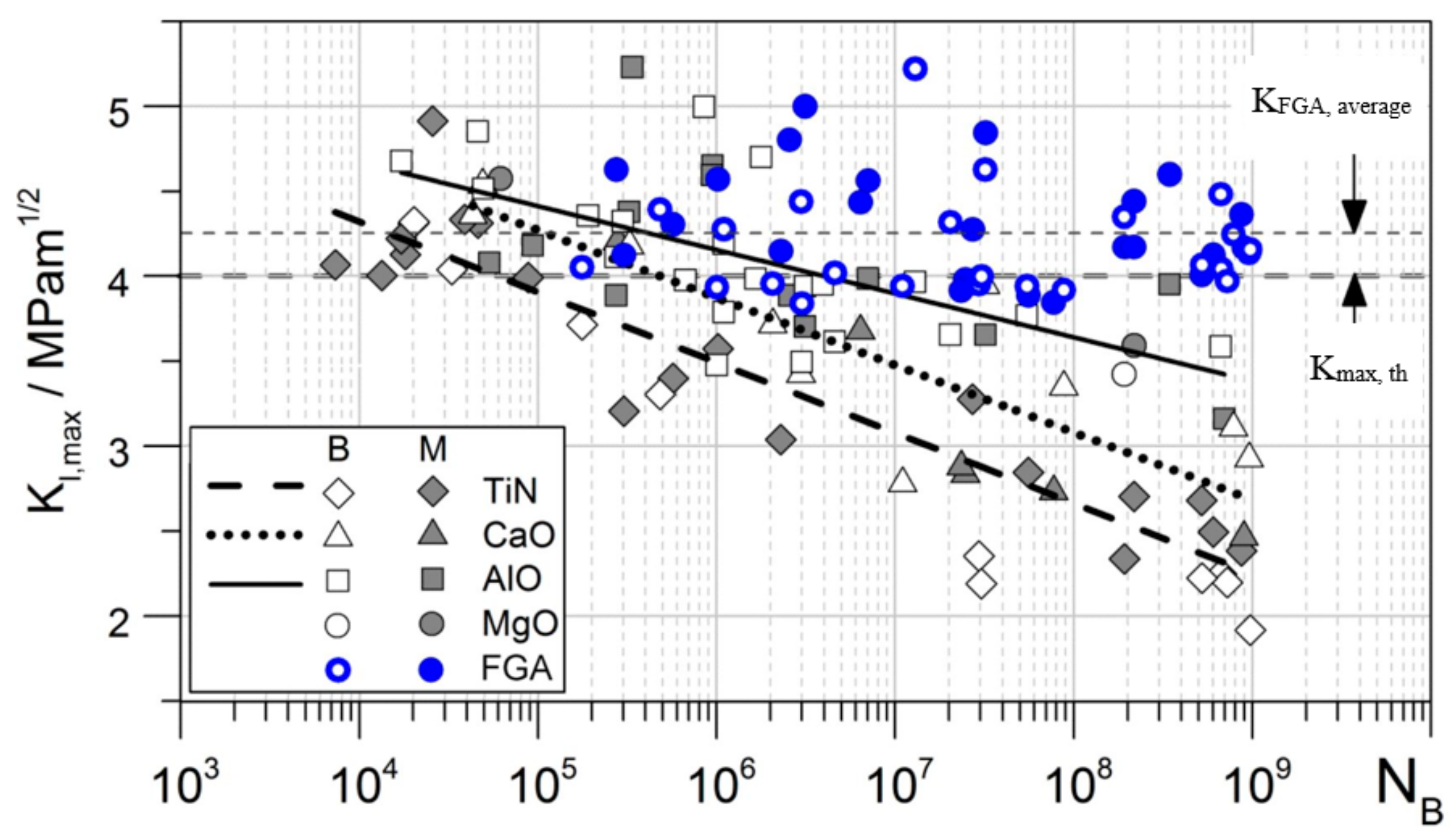
To gain further insight into the underlying mechanism, the size of the crack-initiating inclusion as well as of the FGA and the fish-eye were investigated in more detail. To describe the crack propagation around inclusions the a r e a − Model [34,87] developed by Murakami is now well established. It uses the projected area perpendicular to the applied load to describe the stress-increasing effect of a defect by transformation into an equivalent crack for the calculation of the stress intensity factor (SIF). FGA-formation is observed for inclusions with a SIF ΔKInc smaller than the threshold value for long crack propagation ΔKth [15,62,88] and the SIF around an inclusion decrease with increasing lifetime due to the reduced applied stress (white and grey symbols in Figure 2) [56,70].
However if the maximum stress intensity factor Kmax,FGA at the border between the FGA and the fish-eye is determined in analogy to the a r e a − Model by Murakami, using the entire area of the FGA including the non-metallic inclusion, their values match their respective threshold values for long crack propagation of high-strength steels for the respective stress ratio R = −1 of Kmax,th ≈ 4–5 MPam1/2 [8,10,15,89,90]. FGA-formation is only observed if the SIF Kmax of the crack-initiating defect is below the threshold for long crack propagation. If the area of the FGA is used to calculate the resulting SIF at the border between the FGA and the fish-eye (blue symbols in Figure 2), it reaches or exceeds the threshold for long crack propagation Kmax,th [91,92].
Similar results were obtained by Li et al. [56] who reported that the value of the SIF of inner inclusions leads to failure without FGA are 4–5 MPam1/2 and are similar to those of surface defects corresponding to the threshold value for crack propagation, while the SIF values for inclusions with FGA-formation are significantly lower at 2.5–3.3 MPam1/2. In analogy Liu et al. [39] reported that for Ti-6Al-4V the values of the SIF at the border of the RA also corresponds to the threshold for crack propagation in vacuum.
Tests with variable amplitude loadings and a stress ratio of R = −1 have been performed and describe the formation of “tree ring patterns” consisting of alternating ring-shaped fracture surfaces of FGA-morphology for the loading with SIF lower than Kth and smooth fracture surfaces for SIF above Kth [88,93]. Wang et al. describe that the SIF at the border of the FGA can be described as Δ K F G A = E b with E being the Young’s modulus and b being the burgers vector [94], while Yang et al. [89] postulate that this threshold condition for the FGA is achieved when the size of the plastic zone in front of the crack tip equals the crack propagation per cycle [95]. Abdesselam et al. state that for testing on a martensitic steel at different temperatures (20 °C, 200 °C, 400 °C), the size of the FGA decreased with increasing temperatures at a constant applied stress amplitude. As a consequence, the critical stress intensity factor varied, while the calculated plastic zone size after Irwin remained constant. They therefore suggest a correlation between the plastic zone size and the microstructural barriers, mainly martensitic laths in their case [62].
Given that the fish-eye morphology is formed under stable crack propagation of long cracks it has been shown that the time for the crack initiation and propagation inside the FGA equals more than 90% of the lifetime in the VHCF-regime [13,18,86,96,97]. Considering the size of the FGA and the cycles it takes to form the FGA and the crack to propagate into the fish-eye the average propagation rate inside the FGA can be calculated and is in the range of 10−13–10−11 m/cycle [9,13,82,97,98]. This average crack propagation per cycle is below the lattice spacing, so continuous crack propagation is impossible and the historical crack propagation concepts are not sufficient to describe it [9].

2.2.2. Characteristics Observed by Computed Tomography

The analysis of crack initiation and early crack propagation during VHCF failure is complicated by the fact that the failure is dominated by processes inside the specimen. Because of the very localized processes and the resulting small dimensions to be investigated, there is an additional requirement for a very high resolution. because of those conditions computed tomography using synchrotron radiation (SR µ-CT) has gained increasing attention in recent years. Fischer et al. [99] used 3D digital image correlation (3D DIC) on SR µ-CT images of cast iron to calculate 3D strain tensors. Strains of less than 1% could be measured by this method and allowed to detect inhomogeneity due to irreversible deformation and the calculated irreversible strain fields are reported to be able to predict origin of cracks.
Nakamura et al. [100] investigated the crack initiation and early crack-propagation phase in Ti-6Al-4V using SR µ-CT. Four cracks with a length in the grain size range of the tested material (<30 µm) were detected on a specimen that had been previously stressed with 1.1 × 10⁷ cycles. To evaluate the crack growth, the specimen was additionally stressed for 1.325 × 10⁷ cycles and reexamined. Although no crack growth could be observed for the previously detected cracks, the initiation of four additional cracks was observed, which indicated that the failure is determined by multiple competing cracks. Yoshinaka et al. [101] were able to determine the crack-propagation rate of internal cracks to be less than 10−10 m/cycle using SR µ-CT, while a strong increase of the crack-propagation rate to 10−8 m/cycle was observed once the crack reached the surface. The crack propagation rate of internal cracks corresponds to the crack-propagation rate of surface cracks in high vacuum, while it corresponds to the crack-propagation rate of surface cracks in air as soon as surface contact is reached. The slow crack-propagation rate of internal cracks was thus attributed to the vacuum-like conditions inside the specimen. Those crack-propagation rates were validated in a recent study by Yoshinaka et al. [102] using SR µ-CT, and crack-propagation rates of 10−13–10−11 m/cycle were determined for ΔK-regime below 5 MPam1/2. During the investigation, 28 cracks were detected within one specimen. The crack-initiation life widely varied from 20% to 70% of the average lifetime. Neither the crack-initiation time nor the size of the initiation site had an effect on the subsequent crack-propagation rate, therefore the surrounding microstructure was evaluated as the dominant influence of internal fatigue, rather than the crack origin. Liu et al. [103] analyzed the structure of FGA of a martensitic-bearing steel (100 Cr6) by usage of synchrotron radiation nano-CT and 3D image processing. They found that the granular areas on the fracture surface inside the FGA observed by SEM consists of several subgrains that are tens to hundreds of nanometers in size. It was stated that the resolution of nano-CT is not sufficient, but that at present, the grain refinement was not observed and therefore the FGA-formation mechanism might be based on a rearrangement of the observed subgrains.

2.2.3. Characteristics Observed by Focused Ion Beam and Ion-Induced Secondary Electron Imaging

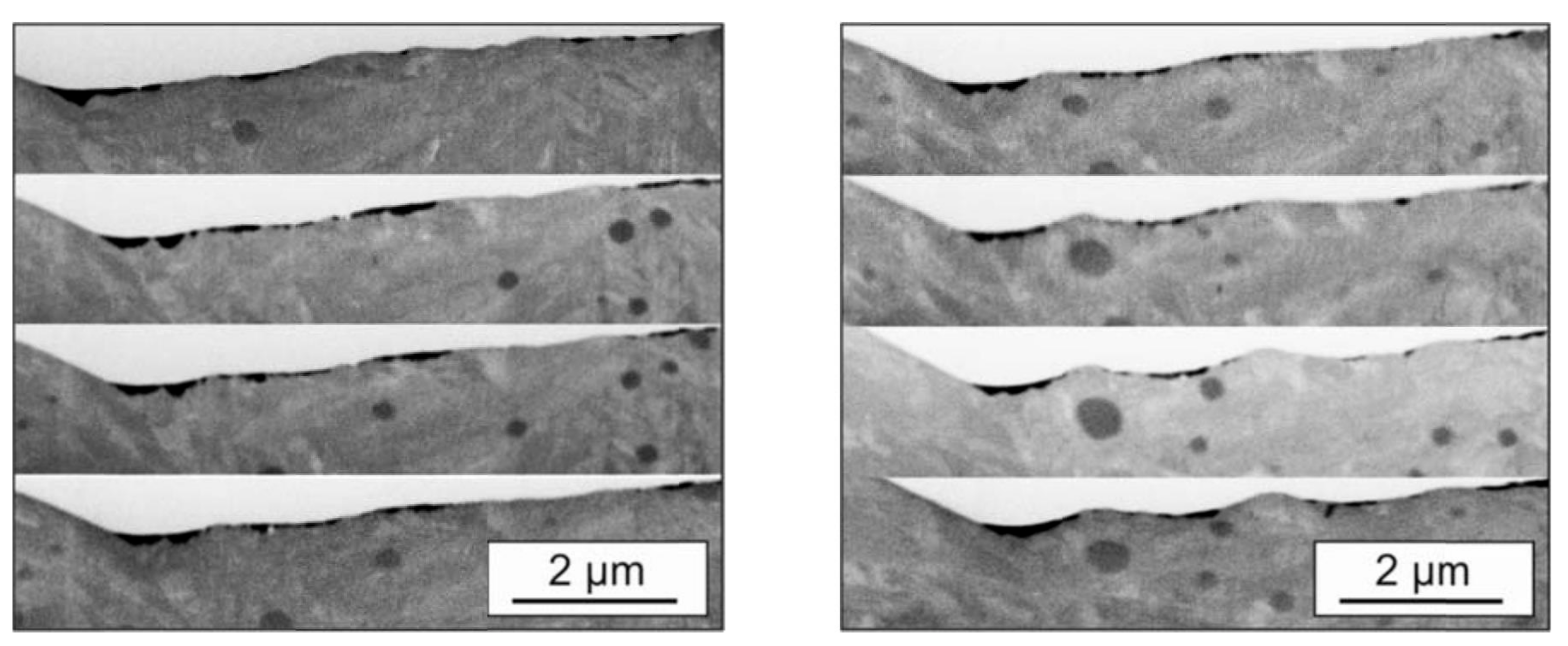
In order to clarify the influence of carbides (see dark particles in Figure 3) on the FGA-formation Grad [13] performed an investigation using ion-induced secondary electron imaging (ISE) on serial cuts (cut distance 0.2 µm) generated by focused ion beam (FIB) at a fracture surface with FGA. No delamination of the carbides below the fracture surface were detected and no carbides exposed by the fatigue crack could be observed.
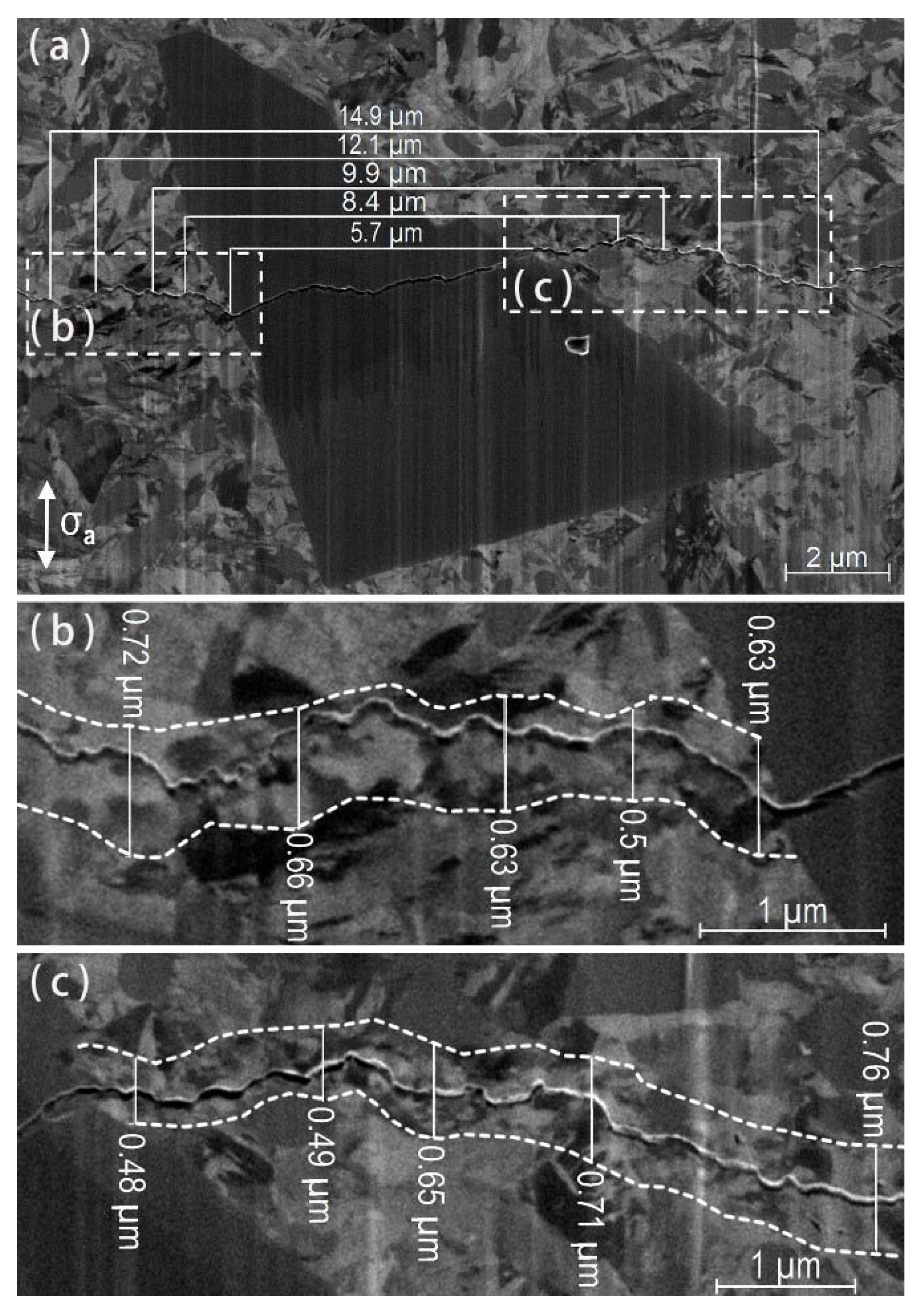
Spriestersbach and Kerscher [90] used ISE imaging, which uses grain orientation for contrast generation, to evaluate the FGA thickness of a VHCF crack exposed by serial grinding, which did not lead to final failure. Thus, the FGA thickness of a closed VHCF crack was determined more accurately than by assuming twice the thickness measured below one side of a fracture surface (see Figure 4).
The determined FGA thickness was 500 nm for a SIF of 2 MPam1/2 and up to 1.2–1.4 µm for a SIF in the threshold range for long crack propagation of 4 MPam1/2. The measured thickness of the FGA was additionally compared to the calculated plastic zone size perpendicular to the crack propagation direction and showed good agreement (see Figure 5)

2.2.4. Characteristics Observed by Electron Backscatter Diffraction and Inverse Pole Figure

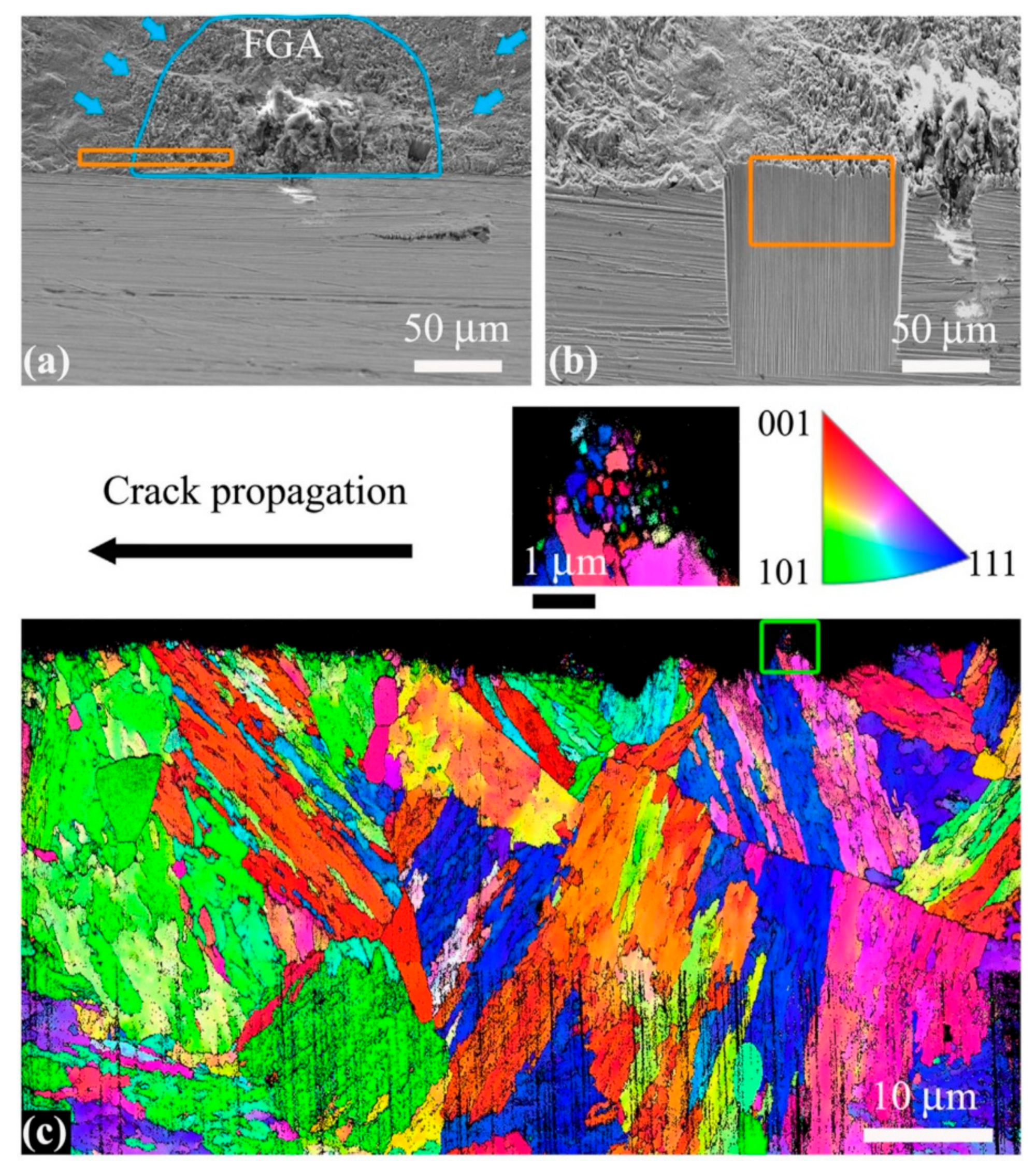
Sun et al. [88] used electron backscatter diffraction (EBSD) imaging to investigate the grain refinement of a crack with FGA-formation of a martensitic steel 0Cr17Ni4Cu4Nb (AISI630) under variable amplitude loading (see Figure 6). A discontinuous graded layer structure (consisting of some areas with ultrafine and coarse grains and other areas with coarse grains only) as shown in the EBSD image in Figure 6c) has been reported. To further analyze and describe the FGA secondary cracks has been analyzed via EBSD. The propagation of the crack within the FGA as well as along the interface between the fine-grained area and the surrounding matrix was observed.
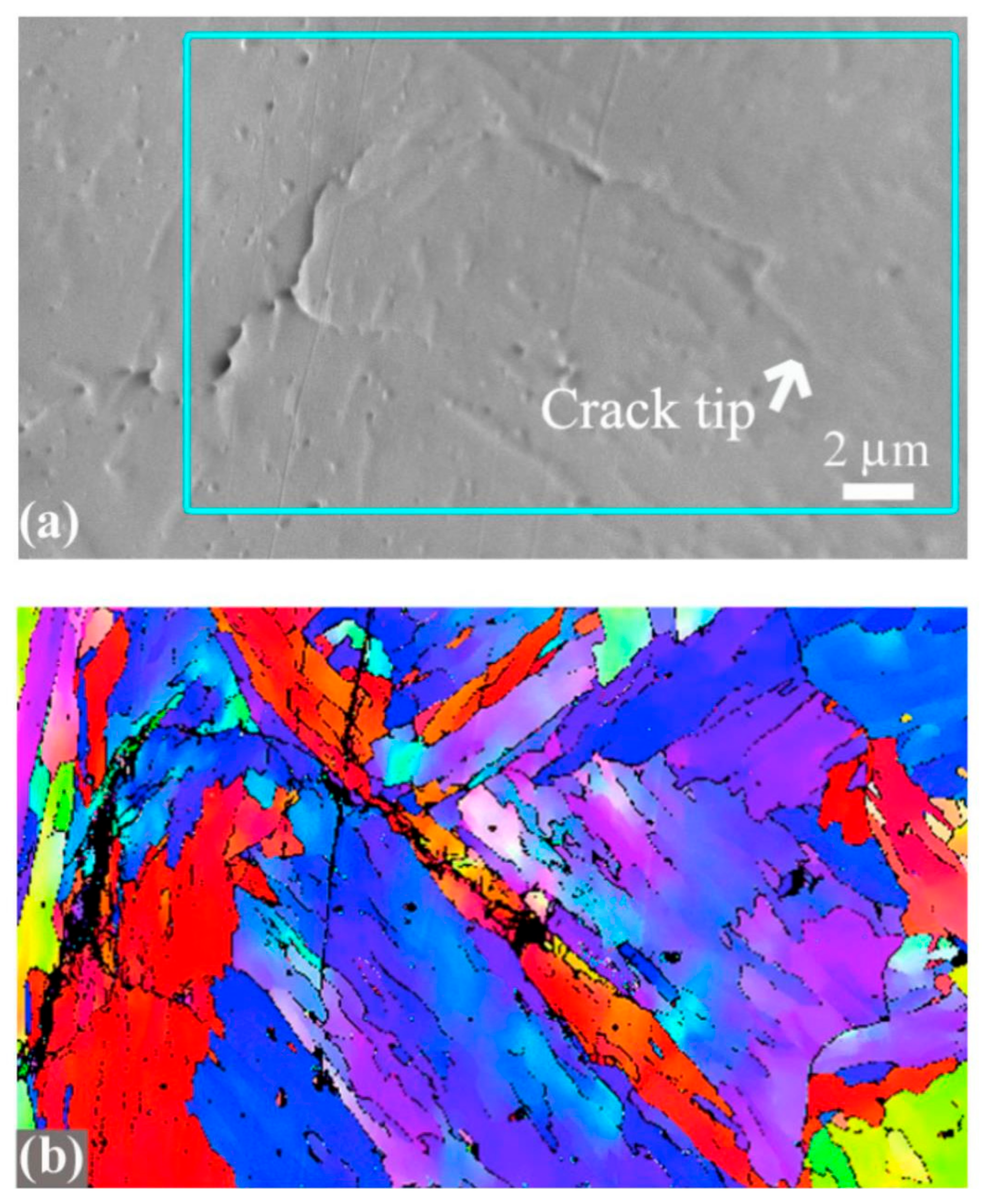
In addition, it is reported that the FGA is not continuously formed on both sides of the fracture surfaces and that a gradient layer with respect to grain size is also formed locally before the crack tip. Therefore, grain refinement is evaluated to be a result of the interaction of dislocations in the immediate vicinity of the crack-initiation site or crack tip because of local high stress. Based on those observations, Song and Sun [104] analyzed the microstructure around a previously introduced fatigue crack after an additional compressive fatigue test for the same material, to clarify the influence of repeated compressive stresses between fracture surfaces on the FGA-formation process, by means of EBSD (see Figure 7).
The martensitic stainless steel 0cr17ni4cu4nb (AISI630), which showed FGA-formation under variable amplitude loading at an amplitude of 430 MPa after 5 × 10⁶ cycles with a stress ratio of R = −1 [88], shows no FGA-formation on a previously created crack after the same number of cycles during compressive load (6max = 0 MPa 6min = −430 MPa). Song and Sun mention that the test was done in air environment, but refers to experiments of Tofique et al. [85] and state that according to Tofique et al. the FGA feature and the fine-grained layers are also observed for fracture surface in air for cold-rolled stainless steels in VHCF-regime. Since no grain refinement was observed after the compressive fatigue test, they therefore conclude that the FGA is not formed by a large number of repeating fracture surface contacts due to compressive loadings, but that FGA is rather formed during the crack-initiation process. Because of the uniqueness of Tofique et al.’s results, from the authors point of view, the tests should also be performed under vacuum conditions to confirm this conclusion.
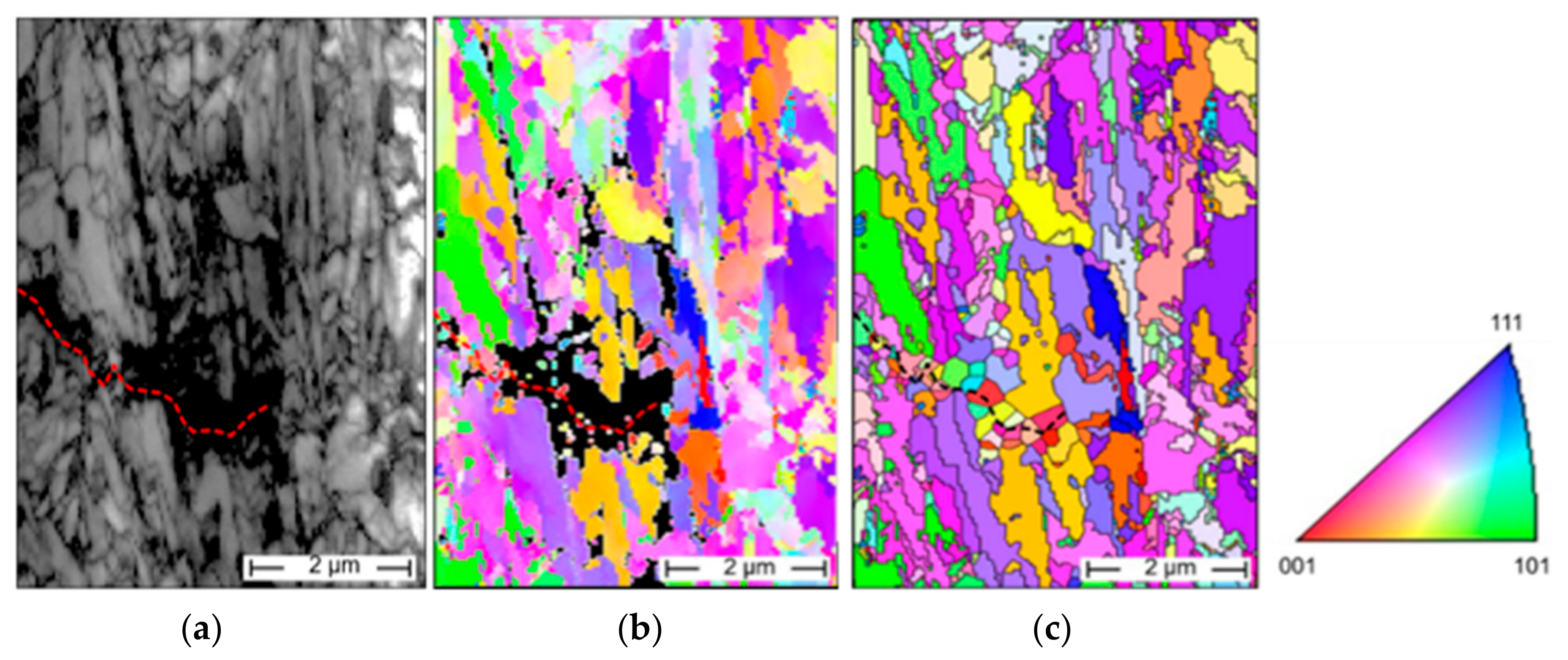
Spriestersbach [91] recently published a study to clarify the influence of the FGA on crack propagation during crack initiation and early crack propagation. For this purpose, a VHCF fatigue test was carried out on a sample with an artificial surface defect in a vacuum environment and the microstructure of the FGA was analyzed by means of EBSD (see Figure 8).
Figure 8a shows the indexing confidence map as a greyscale image, with a high degree of agreement in the light areas. The maximum indexing confidence of this measurement is 0.886 and to clean up the map all points with an indexing confidence of less than 0.79 have been removed and are shown as black areas. The size of this area corresponds to the FGA size around the stopped fatigue crack shown by dashed red line and since the expected grain size within this area corresponds to the step size of the EBSD measurement (40 nm), the differentiation of individual grains is much more difficult. Figure 8b shows the corresponding inverse pole figure (IPF)-Map under the assumption that for a grain boundary at least a miss orientation of 10 degrees must be present. The grain structure in the not clearly indexed area was reconstructed on the basis of the few reliable areas by expanding them via the software until they closed the free area as Voronoi-cells (see Figure 8c). Although the grain size is overestimated by this procedure, a clear grain refinement along the crack is still observed.
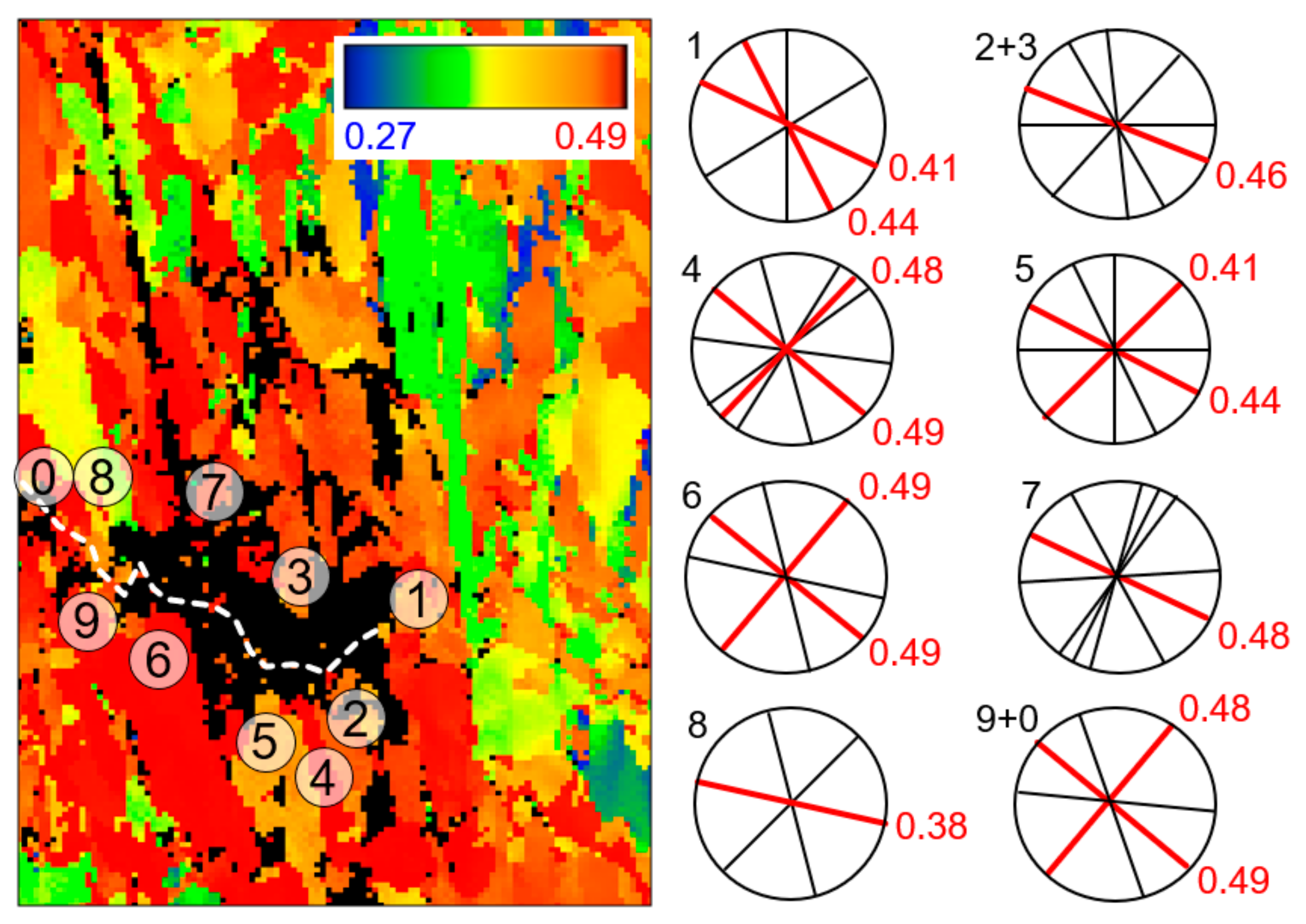
In Figure 8c the crack path is influenced by the microstructure and is thought to lead to the observed rough fracture surface within the FGA. To clarify the influence of the microstructure on the crack propagation in the early phase, a map of the sliding systems with the highest Schmid factor was created (Figure 9).
As shown in Figure 9 the crack path within the FGA does not occur in favorably oriented sliding systems with respect to the original grain structure. Since the newly formed grains and their orientation cannot be detected with sufficient confidence, their influence on the crack path could not be investigated in more detail.

2.2.5. Characteristics Observed by Transmission Electron Microscopy and Selected Area Diffraction

Selected area diffraction (SAD) of transmission electron microscopy (TEM) lamellas prepared by FIB is commonly used to analyze the grain refined regions resulting from VHCF tests. Sakai et al. [12] observed that the diffraction patterns inside the FGA displayed ring-like structures, that indicate the presence of many small grains in the analyzed area, while the corresponding image in an area outside the FGA displayed spot-like patterns peculiar to the original relatively coarse martensitic structure. The fine granular area observed at the fracture surface via SEM was shown to be a three-dimensional layer of refined grains with a thickness of about 40 nm. Grad et al. [15] reported similar findings and confirmed a drastic grain size reduction inside the FGA in comparison to neighboring areas. The analysis of the ring-like patterns (Debye Rings) gave an average grain size estimation of about 70 nm inside the FGA and the patterns indicated, that those grains still consisted of martensite and austenite phase. While describing a high dislocation density, which made the observation of the smallest grains via TEM difficult, Grad et al. state that the high miss orientation observed via TEM inside the FGA suggest large grain boundaries. Additionally, an arrangement of dislocations was observed within a martensitic needle, which could be a pre-stage of dislocation cells. Chai et al. [105] report the finding of special dislocation structures formed in the FGA during VHCF fatigue by means of high resolution TEM, too. The observed structures correspond to a special type of dislocation sub cells with the size of about a few hundred nanometers. The dislocation density inside those sub cells is relatively low, while the density inside the cell boundaries is neither constant nor homogeneous. Some areas of the cell boundaries show a very high dislocation density, while other areas display a low dislocation density. The grain refinement inside the FGA by means of SAD has been since confirmed in several studies [14,83,85], with observed thickness of the fine-grained layers ranging from 100–300 nm [85], 150–300 nm [83] up to a range of 500–800 nm [14]. In addition, a gradient in regards to the grain size inside the FGA has been found. The smallest grains are observed in the direct vicinity of the crack-initiation site with an increasing grain size along the crack path [83,106]. This gradient is also reported at the border between the fine- and coarse-grained volume, corresponding to a mostly smooth transition rather than a harsh cut [83]. Furthermore, grain refinement in front of a VHCF-crack tip has been observed by means of SAD [83,88].
Sun et al. [88] carried out TEM and SAD investigations of samples after variable amplitude loading and resulting “tree ring pattern” consisting of alternating rough fracture surface areas (generated at low stress amplitude) and smooth fracture surface areas (generated at high stress amplitude). Grain refinement could be detected locally isolated under the smooth areas. In contrast to the reported continuous fine grain layers on both sides of VHCF-cracks [14,83,85], Sun et al. observe a discontinuous grain refinement under both smooth and rough areas, they therefore conclude that the grain refinement occurs during the low-stress amplitude in front of the crack tip before the smooth fracture surface is generated by the high stress amplitude and the resulting high crack propagation rate. In addition, the composition of the refined grains has been examined using electron energy loss spectroscopy for elemental composition analysis and confirmed that the fine grains are a resultant of deformation other than oxidation.

2.2.6. Characteristics Observed by Atom Probe Tomography

To obtain additional conclusions about the microstructural changes within the FGA, Spriestersbach [91] analyzed the FGA using atom probe tomography (APT). For this purpose, the basic material as well as the material within a fish-eye area and from the FGA area around non-metallic inclusions as well as artificial FIB defects were examined. By means of APT, phases, carbides and grain or phase boundaries of the martensitic and bainitic states can be distinguished because of the local carbon concentration. Both in the original state and in the area of the fish-eye fracture surface near an inclusion, all other alloying elements were observed to be homogeneously distributed. In contrast, the alloying elements within the FGA showed clear deviations from this homogeneous distribution. Elements such as Al, Cr, Si, Mn, or P showed local enrichment or local depletion, with an increased number of fine precipitates being observed within the FGA. These changes were observed around inclusions as well as artificial defects, but not in the initial structure or in the area of the fish-eye, Spriestersbach therefore concludes that they must result from the VHCF process. By analyzing the mean values of the concentrations of all investigated areas, an enrichment of the FGA with elements from the surrounding volume could be negated. The local concentration differences are therefore attributed to a local redistribution within the FGA. Spriestersbach refers to similar results acquired via APT by Sauvage et al. [107] and Abramova et al. [108] on fine grained areas in samples after severe plastic deformation (SPD), and by Kang et al. [109,110] and Li and Herbig [111,112] for investigations of fine-grained white-etching cracks (WEC) occurring under rolling stress in high-strength steels. Spriestersbach attributes the enrichment of certain elements by redistribution inside the FGA to the fact that those elements preferentially diffuse into the distorted lattice areas of dislocations and thus accumulate during the formation of dislocation cells. The intense sustained dislocation movement during VHCF loading and the resulting highly cyclic local plastic deformation is believed to compensate for missing enabling factors such as higher degrees of deformation and elevated temperatures present in the case of enrichment during SPD and WEC-formation.

3. Postulated Models Describing the Mechanism of Very High Cycle Crack Initiation and FGA-Formation

As briefly mentioned earlier it remains unknown if the FGA-formation is a prerequisite or a consequence of the long crack initiation. Also, it is unclear if the cracks propagating inside the FGA should be considered short or long cracks. Since they propagate with stress intensity factors beneath the threshold for long crack propagation they could therefore be considered short cracks, while the plastic zone in front of the crack tip is very small compared to the crack length which would grant a property to describe them as long cracks. Despite those uncertainties regarding these points, several different hypotheses to describe crack initiation, the early crack propagation, and the formation of the FGA exist. They are given below.

3.1. Hydrogen-Assisted Crack Growth of Short Cracks

Murakami et al. [9,35,51,86] postulated a hydrogen-induced short crack propagation as a result of the hydrogen preferentially attached to non-metallic inclusions during the heat treatment. Takai et al. [113] observed trapped hydrogen around the non-metallic inclusions via secondary ion image analysis. The localized increased hydrogen content is supposed to lead to hydrogen embrittlement in the immediate vicinity of the inclusion and thereby suppresses the crack-closure effects, which usually determine the fatigue strength. To evaluate the influence of hydrogen on the FGA-formation a test with specimens containing different hydrogen contents due to their heat treatments was performed. Murakami et al. observed smaller FGAs for the specimens with lower hydrogen content. The specimens containing the least hydrogen showed crack initiation at non-metallic inclusions but also at large bainitic areas. Since FGA was only observed for crack initiation around non-metallic inclusions and not for bainitic areas-induced crack initiation Murakami et al. attributed the FGA-formation to the hydrogen trapped around the inclusion [51].
According to Narita et al. [114], the hydrogen in the crack tip leads to an increase in the SIF, which promotes short crack growth and the microstructural barriers are therefore no longer sufficient to arrest the crack. The influence of hydrogen and the threshold condition for the hydrogen-induced crack propagation are described by Yang et al. [95]. Since the trapped hydrogen around non-metallic inclusions only has an effect within the plastic zone forming in the respective cycle it is stated that hydrogen-induced crack propagation only takes place as long as the crack propagation per cycle is smaller than the plastic zone in front of the crack tip. Therefore, the postulated hydrogen-induced crack growth changes into a long crack growth as soon as the crack propagation per cycle exceeds the size of the plastic zone [95].

3.2. Dispersive Decohesion of Spherical Carbide Model

Shiozawa et al. [10,23,115] postulated a mechanism based on carbide detachment in the immediate vicinity of non-metallic inclusions. Within the FGA, an increased carbon content around the non-metallic inclusion was determined using electron probe microanalysis (EPMA). While the investigation of fracture surfaces without the FGA shows a homogeneous carbon distribution with a lower carbon density. On the basis of the results, the increased carbon content is attributed to carbide particles remaining in the fracture surface. The formation of the FGA is described by the “dispersive decohesion of spherical carbide” model. Based on the examinations and computer simulation, this model assumed that individual micro cracks occur as a result of the cyclic stress caused by carbide detachment. These micro cracks grow separately and then merge into a long crack that can propagate during continuous cyclical stress. As a result, the crack runs along the detached carbides, creating the rough surface observed inside the FGA [23,115].

3.3. Polygonization with Nucleation and Coalescence of Micro-Debondings

Another approach to explain the formation of the FGA as well as the fatigue in the VHCF-regime was postulated by Sakai et al. [12]. According to Sakai et al., the fine-grained three-dimensional layer with the size of FGA is formed around the failure inducing non-metallic inclusion due to the long-term exposure to polygonization. Along the boundary layer between this fine-grained zone and the original microstructure, micro cracks are supposed to initiate continuously as a result of further cycles. After sufficiently long periods of cycles, these micro cracks then coalescence together and form a propagating crack. In contrast to the mechanisms described above the formation of the FGA is supposed to be the cause for the late crack initiation and the VHCF failure in general.
Chai et al. [105,116] postulate a similar mechanism and conclude that the FGA-formation is a result of localized plastic deformation. Because of the cyclic stress, the dislocations are supposed to rearrange into dislocation cells and plastic recrystallization is expected to occur in the area of increased stress around the non-metallic inclusion. However, while forming the FGA, additional micro pores are supposed to form because of dislocation annihilation acting as crack initiation sites. Zhu et al. [117] postulate the “fragmentation of martensitic laths and formation of dislocation cells” mechanism which is also based on the formation of dislocation cells as a result of annihilation of low angle boundaries and the breakdown of martensitic laths due to localized plastic strain around critical inclusions. Further the extension of fine grains with newly formed boundaries/interfaces and micro cracks are supposed to result in a widespread interface linking or coalescence forming interior small cracks during the process and thus building the FGA. Song and Sun [104] postulate a very similar model that is also based on the rearrangement of dislocations into dislocation cells resulting in grain refinement. In contrast to the models described above, they postulate that micro crack initiation might also occur in front of the crack tip depending on the local microstructure resulting in the discontinuous formation of the fine-grained layer. For the mechanism of rearrangement of dislocations into dislocation cells Van Swam et al. [118] is cited and it was observed by Koster et al. [119] that those dislocation cells led to the formation of small sub grains or low angle boundaries in ferrite grains in VHCF regime.

3.4. Superplastic Effects and Vortex Shaped Flow Resulting in FGA

It is postulated by Shanyavskiy [120] that the crack initiation in the VHCF-regime occurs due to superplastic effects in the plane normal to the loading direction. By superimposing tensile stresses (or compressive stresses) in the loading direction and the resulting compressive stresses (or tensile stresses) in a vertical position at the equator of an inclusion, the critical shear stress is locally exceeded within the matrix and therefore a superplastic state is reached, resulting in a vortex-shaped plastic flow in this area. As a result, nanostructures are formed from cylindrical, ellipsoidal, and spherical particles, which are formed into balls by “rolling-up” as a result of the cyclic tensile/compressive stress and therefore forming a nanostructured layer. These newly formed nano grains rotate every half cycle under cyclic stress, which reduces the grain boundary strength allowing the grains to detach and form a free surface. The typical round shape that has been observed on the fracture surface inside the FGA is postulated to result from this rolling process [120].

3.5. Numerous Cyclic Pressing

The mechanism of “numerous cyclic pressing” (NCP) was postulated by Hong et al. and assumes that the necessary conditions for the FGA-formations are inert environmental conditions, frequently recurring fracture contact, and a low crack propagation speed [14,97]. It is stated that a crack initiates in the interface between inclusions and matrix because of highly localized plastic deformation and the formation of the fine-grained layer is attributed to crack-closure effects. The crack flanks of the initiated VHCF-crack are supposed to lead to the formation of the observed fine-grained layer due to the repeated contact during the cyclic loading. This process is continuing, until the crack length or the FGA size, which is present at the transition from FGA to fish-eye, reached the critical size of the FGA for a SIF in the range of the threshold value for long-crack growth. The crack initiation process, as well as the crack propagation with low crack propagation rates are not described in more detail. The FGA-formation is therefore not considered responsible for the slow crack initiation or the VHCF-failure but is described as a consequence or a marginal phenomenon. The NCP model further describes two necessary conditions for FGA-formation, the presence of compressive stresses between the fracture surfaces resulting in repeated fracture surface contact and a sufficient number of load cycles to generate sufficient number of fracture surface contacts [17].

3.6. Cold Welding-Induced Grain Refinement for Titanium Alloys

Another postulated mechanism that is based on the repeated contact of the fracture surface because of the cyclical stress and crack-closure effects is the approach according to Oguma and Nakamura [81]. In contrast to the NCP model by Hong et al., both the low crack propagation rate and the grain refinement within the FGA are attributed to a type of cold welding of the fracture surfaces through repeated fracture surface contact under vacuum conditions or in the interior of the materials and it is suggested that the formation of the FGA correlates strongly with the fraction of surface coverage of absorbed gas [81]. Based on the model of Oguma and Nakamura, Ogawa et al. [93] postulate that the low stress amplitudes that lead to VHCF failure result in shear cracks and crack deflection in several crack planes. Because of the interaction of the roughness, there are locally high strains in the crack tip, which lead to the formation of very pronounced point defects that are supposed to support cold welding and therefore grain refinement is observed as a result of different crack paths besides cold welded former fracture surfaces. The FGA is formed as a direct result of the cold welding necessary for the VHCF failure during early crack growth and is therefore to be understood as an indirect cause.

3.7. Stage I like Crack Propagation with Grain Refinement in the Crack Wakes

Another mechanism postulated by Abdesselam et al. [62] assumes that the early crack growth in the VHCF-regime initially occurs very slowly in mode I like propagation with SIFs smaller then Kth,FGA. Accordingly, the stress increase around inclusions, for example due to the different moduli of elasticity of matrix and inclusion, leading to the fracture of the non-metallic inclusion and thus to first initiate a crack during the cyclic loading. The resulting plastic zone, which is smaller than the martensite needle length or three times the martensite needle thickness is formed. The crack is assumed to propagate slowly and strongly affected by microstructural barriers with propagation similar to stage I-like crack propagation while leaving a plastically deformed area along the crack wakes. Because of the slow propagation rate this plastic deformation accumulates locally for many cycles leading to the microstructural changes. Because of these localized plastic deformations, the very dislocation-rich martensitic structure is supposed to rearrange into dislocation cells, which are observed as fine-grained area along the FGA fracture surface. When the plastic zone reaches the martensite lath length, or three times the martensite needle width, the crack is supposed to switch to stage II crack propagation under vacuum conditions, therefore forming the fish-eye fracture surface. Because of the accelerated crack propagation rate, the local plastic deformation is supposed to be no longer sufficient to allow for grain refinement inside the plastic zone at this stage of the fatigue process [62].

3.8. Local Grain Refinement at the Crack Tip

Another postulated mechanism that is based on the rearrangement of dislocations into dislocation cells and resulting in grain refinement is the model of local grain refinement at the crack tip first described by Grad et al. [13,15] and then expanded by Spriestersbach and Kerscher [90]. According to Grad et al. a crack initiates in the immediate vicinity of a non-metallic inclusion because of the stress-increasing effect of the inclusion. In contrast to the other models the crack is rated to be a long crack, since the ratio of crack length to plastic zone size is high (50 < a/rp < 80) [90] and thereby the cracks cannot be seen most likely as short cracks but they are supposed to be long cracks as defined by Miller [121]. Since the SIF at the crack tip Kmax is below the threshold for long crack propagation of the original microstructure Kth,global the cracks are seen as non-propagating long cracks by definition. While the formation mechanism of the fine-grained area is similar to the model of Sakai, the dislocation rearrangement and the formation of dislocation cells only takes place in a much more localized area inside the plastic zone caused by the non-metallic inclusion. From these dislocation cells, first sub grain boundaries and then large-angle grain boundaries are supposed to form under further cyclic loading. This newly formed, refined microstructure decreases the local threshold against long crack propagation Kth,local and therefore enables crack propagation within the fine-grained area as soon as Kth,local is decreased below Kmax. This process of grain refinement and long crack propagation is supposed to repeat itself continuously or cyclically as a result of the stress increase at the crack tip until the Kmax,FGA exceeds the global threshold Kth,global. The formation of the FGA is no longer necessary and subsequently, stable long crack propagation occurs without the formation of the fine-grained layer within the fish-eye.

4. Discussion

Given the above stated observed characteristic of the FGA, as well as the framework conditions that favor its development and the postulated models of the formation mechanism, an evaluation of these underlying mechanisms will now be carried out within this chapter.
Concerning the model first postulated by Murakami et al. [9], which is based on hydrogen-induced short crack growth, resulting in the granular area, the following questions arise in consideration of the present state of knowledge; while trapped hydrogen is observed around non-metallic inclusions, influencing the crack propagation of short cracks, only the rough surface can be explained by hydrogen-induced short crack propagation. The actual observed grain refinement however is neither considered nor explainable by this model. Furthermore, the FGA-formation is also observed around artificial defects under vacuum conditions where no hydrogen is present [83] and there are results from Karsch et al. [53] observing decreasing FGA-formation for bainitic as well as martensitic structures with increased hydrogen content. For all investigated conditions, hydrogen decreased the fracture toughness and therefore reduced the critical stress intensity factors with increased hydrogen content. Since the characteristic grain refinement process cannot be explained and the presence of hydrogen is not needed for the formation of the FGA, while hydrogen embrittlement might obviously influence the crack propagation (even in the VHCF-regime), from the authors point of view it is not possible to be the root cause for the formation of the FGA nor the failure in VHCF-regime.
A very similar problem arises for the model first postulated by Shiozawa et al. [10], which is based on dispersive decohesion of spherical carbides. Although the rough surface within the FGA observed via SEM would be explained, the formation of the fine-grained three-dimensional layer is inexplicable. In addition, carbides around analyzed VHCF fracture surfaces do not show decohesion, nor is an influence of carbides on the crack path observed [91].
Although the model postulated by Sakai et al. [12] based on polygonization with nucleation and coalescence of micro-debondings involves the formation of a fine-grained layer, the size of the FGA, which far exceeds that of the stress-raising effect of inclusions, cannot be explained. Furthermore, there are observations of secondary cracks propagating in the middle of the FGA instead of the interface of FGA and original microstructure [85,88]. If the coalescence of micro-cracks would be the underlying formation mechanism, a widespread network of micro-cracks should be observed in the FGA, which is not supported by the majority of observations. Also, the slow crack propagation rate evaluated for the crack initiation and early crack propagation is inexplicable by the propagation of short cracks.
The theoretical model for the formation of FGA based on the superplastic effects and vortex shaped flow resulting in FGA by Shanyasvki [120] is based on a high adhesion between the inclusion and the surrounding matrix. This adhesion however is not present in the case of artificial defects and therefore the formation of an FGA around them when tested in vacuum [84] are inexplicable by this model.
The model for the FGA-formation based on NCP by Hong et al. [14] give an explanation for the formation of a fine-grained layer, as well as the observed size of it. The fact that FGA-formation can only be observed in the VHCF-regime is attributed to the cycles required to form the fine-grained layer by repeated surface contacts. Also, the tendency of the FGA being less pronounced with increasing stress ratio is explained because of the decreasing compressive stresses between the fracture surfaces. However, the formation of the FGA for positive stress ratios is only explicable by assuming crack closure effects overcompensating the loading conditions. Also, the very slow crack propagation rate that is observed within the FGA is not explainable by short crack propagation and the observation of fine-grained areas ahead of the crack tip [88,91] is inexplicable by this model. Also, the recent observation [104] that compressive loads that lead to FGA-formation during fatigue testing did not form an FGA during a compressive fatigue test on a pre-cracked specimen suggest that the repeated fracture surface contact is not the underlying mechanism of FGA-formation.
The model based on cold welding-induced grain refinement first postulated by Oguma and Nakamura [81] sharing similar explanations to the NCP model, for the formation only being observed in the VHCF-regime and for the diminishing tendency of FGA-formation with increasing stress ratio could explain the slow crack propagation rates observed because of a repeated cold-welding process. However, the different grain orientations detected by SAD would not be expected by a process of different crack paths and repeated cold welding of the previously generated fracture surfaces. Also, the vacuum dependence of the formation of FGA [81,83,84] can be explained by this model, however, the formation of FGA at surface cracks reported for cold rolled stainless steel [85] is in contradiction to the postulated formation mechanism based on cold welding.
The model of Stage-I-like crack propagation with grain refinement in the crack wakes proposed by Abdesselam et al. [62] shares the strengths and weaknesses with the NCP model. While explaining the fine-grained layer and also explaining the FGA sensitivity to stress ratios, the low crack propagation rate as well as the observation of grain refinement in front of the crack tips are inexplicable by this model.
The model of local grain refinement at the crack tip first proposed by Grad et al. [15] and then extended by Spriestersbach [91] is based on the propagation of long cracks due to rearrangement of dislocations and consequently grain refinement resulting in a locally reduced threshold. The rearrangement of dislocations followed by formation of dislocation cells [118] and the formation of small sub grains and low angle boundaries were observed in steels in the VHCF regime [119] caused by local plasticity [122]. A decrease in the threshold for long crack propagation and higher crack growth rates have been observed for fine grained steels [27,123] and generally in fine-grained metals [124,125]. Therefore, the formation of a fine-grained layer according to this model is not only explainable but is a necessary condition for VHCF failure. In addition, the correlation between the increasing thickness of the FGA with the plastic zone size for increasing crack length, as well as the gradient in regards to the increasing grain size along the crack path inside the FGA can be explained. The slow crack propagation rate can therefore be explained by the repeated process of grain refinement to reduce the threshold value for crack propagation locally within the refined microstructure and the subsequent need for grain refinement once the crack propagated to the original microstructure. The tendency of decreasing FGA-formation with increasing stress ratio can be explained by a decreasing threshold for crack propagation [58,59], as well as the decreasing cyclic plastic zone size [126] that might result in the absence of dislocation cell formation and the resulting grain refinement. In analogy, the vacuum-like conditions that seem to be beneficial for FGA-formation can be explained by the increasing plastic zone size [78,79] and the easier movement and interaction of dislocations under those conditions [80] resulting in beneficial conditions for rearrangement into dislocation cells with subsequent grain refinement. However, the reported formation of FGA-like morphologies due to cyclic loading with Kmax < Kth on previously generated fracture surfaces reported by Nakamura [61] is inexplicable with this model. It is worth mentioning that the observed grain refinement is not necessarily generated by the same mechanism responsible for FGA-formation in the VHCF-regime.

5. Conclusions

Because of the fact that FGA corresponds to a three-dimensional fine-grained layer, early models that are based on hydrogen-induced short crack propagation or the decohesion of carbides, that neither take grain refinement into account nor explain it can be regarded as disproven. As a result of the observed FGA-formation around artificial defects, it is evident that the model of vortex shaped flows is not able to explain the formation mechanism due to the lack of adhesion between the defect and the surrounding matrix. Similarly, the model based on FGA-formation before crack propagation by polygonization due to the stress-increasing effect of inclusions with subsequent coalescence of micro-cracks cannot explain the size of FGA in the crack propagation direction.
A detailed analysis of the effect of load ratio in regards of compressional testing is important from the authors point of view. If the formation of the FGA is based on the dislocation rearrangement and dislocations cells formation resulting in grain refinement a symmetrical decrease in the FGA is expected when superimposed with positive or negative mean stresses. However, if the FGA-formation is based on the compressive forces between previously generated fracture surfaces, the decrease in FGA-formation which is observed for increasing positive mean loads should lead to a stronger formation under negative mean stress. The effect of cyclic creep, as well as the influence of the threshold value for crack propagation should be considered while comparing different load ratios. Additionally, investigations regarding the shape of the FGA are necessary since contradictory observations exist and the reasons for those different observations are still unknown.
The favorable influence of stress ratio and vacuum-like conditions, and especially the local grain refinement being observed in front of a crack tip of VHCF-cracks, indicate, in the authors’ view, that the grain refinement mechanism is based on dislocation rearrangement and interaction within the plastic zone and not based on cold welding or plastic deformation of the crack wakes due to repeated fracture surface contact. The very slow crack propagation in the early crack growth stage and the observed good agreement between the FGA layer thickness and the plastic zone size are indications for the evaluation of initially non-propagating long cracks, which is why the model of local grain refinement in front of the crack tip currently describe the VHCF behavior and the FGA-formation most accurately. Also, the relatively early crack initiation without further crack propagation observed via SR µ-CT [100] suggests that the interaction of the crack with the surrounding microstructure is responsible for the fatigue failure in the VHCF-regime. This indicates from the authors point of view, that the grain refinement based on dislocation rearrangement into dislocation cells and the formation of new grain boundaries therefore reducing the local threshold for crack propagation enabling the propagation of the VHCF-crack might be the underlying mechanism.
However, further investigations are necessary to perform a more detailed evaluation of the postulated grain refinement models based on dislocation rearrangement and to clarify the question of crack characterization as long or short cracks. Especially the understanding of the influence of microstructure on crack propagation during the crack initiation and early propagation phase seems to be of crucial importance. Investigations on artificial surface defects in vacuum, as well as further investigations using SR µ-CT to evaluate crack propagation and initiation during the formation phase of the FGA seem to be promising. Also, newly developed EBSD-analyzing methods like the one described in [127] might be used for the characterization of the interactions between VHCF-cracks and the microstructure.

Author Contributions

Conceptualization, J.P.S. and E.K.; writing—original draft preparation, J.P.S.; writing—review and editing, E.K.; supervision, project administration, funding acquisition, E.K. All authors have read and agreed to the published version of the manuscript.

Funding

This research was funded by the Deutsche Forschungsgemeinschaft (DFG, German Research Foundation) grant number 408139037.

Conflicts of Interest

The authors declare no conflict of interest.

References

  1. Stanzl, S.E.; Tschegg, E.K.; Mayer, H. Lifetime measurements for random loading in the very high cycle fatigue range. Int. J. Fatigue 1986, 8, 195–200. [Google Scholar] [CrossRef]
  2. Lukas, P.; Kunz, L. Specific features of high-cycle and ultra-high-cycle fatigue. Fatigue Fract. Eng. Mater. Struct. 2002, 25, 747–753. [Google Scholar] [CrossRef]
  3. Murakami, Y. Mechanism of fatigue failure in ultralong life regime. Fatigue Fract. Eng. Mater. Struct. 2002, 25, 735–746. [Google Scholar] [CrossRef]
  4. Bathias, C. There is no infinite fatigue life in metallic materials. Fatigue Fract. Eng. Mater. Struct. 1999, 22, 559–565. [Google Scholar] [CrossRef]
  5. Christ, H.-J. (Ed.) Preface. In Fatigue of Materials at Very High Numbers of Loading Cycles; Springer Fachmedien: Wiesbaden, Germany, 2018. [Google Scholar]
  6. Shaniavski, A.A.; Skvortsov, G.V. Crack growth in the gigacycle fatigue regime for helicopter gears. Fatigue Fract. Eng. Mater. Struct. 1999, 22, 609–619. [Google Scholar] [CrossRef]
  7. Bathias, C. Designing Components against Gigacycle Fatigue. In Proceedings of the International Conference on Fatigue in the Very High Cycle Regime, Vienna, Austria, 2–4 July 2001; pp. 97–109. [Google Scholar]
  8. Sakai, T.; Sato, Y.; Oguma, N. Characteristic S-N properties of high-carbon-chromium-bearing steel under axial loading in long-life fatigue. Fatigue Fract. Eng. Mater. Struct. 2002, 25, 765–773. [Google Scholar] [CrossRef]
  9. Murakami, Y.; Nomoto, T.; Ueda, T. Factors influencing the mechanism of superlong fatigue failure in steels. Fatigue Fract. Eng. Mater. Struct. 1999, 22, 581–590. [Google Scholar] [CrossRef]
  10. Shiozawa, K.; Morii, Y.; Nishino, S. Subsurface Crack Initiation and Propagation Mechanism under the Super-Long Fatigue Regime for High Speed Tool Steel (JIS SKH51) by Fracture Surface Topographic Analysis. JSME Int. J. 2006, 49, 1–10. [Google Scholar] [CrossRef] [Green Version]
  11. Ochi, Y.; Matsumura, T.; Masaki, K.; Yoshida, S.-Y. High Cycle Rotating Bending Fatigue Property in Very Long Life Regime of High Strength Steels. In Proceedings of the International Conference on Fatigue in the Very High Cycle Regime, Vienna, Austria, 2–4 July 2001; pp. 81–88. [Google Scholar]
  12. Sakai, T.; Harada, H.; Oguma, N. Crack initiation mechanism of bearing steel in very high cycle fatigue. In Proceedings of the ECF, Alexandroupolis, Greece, 3–7 July 2006; p. 16. [Google Scholar]
  13. Grad, P. Rissinitiierung und Rissausbreitung im VHCF-Bereich des hochfesten Stahls 100Cr6 Dissertation; Fachbereich Maschinenbau und Verfahrenstechnik; Technische Universität Kaiserslautern: Kaiserslautern, Germany, 2013. [Google Scholar]
  14. Hong, Y.; Liu, X.; Lei, Z.; Sun, C. The formation mechanism of characteristic region at crack initiation for very-high-cycle fatigue of high-strength steels. Int. J. Fatigue 2016, 89, 108–118. [Google Scholar] [CrossRef] [Green Version]
  15. Grad, P.; Reuscher, B.; Brodyanski, A.; Kopnarski, M.; Kerscher, E. Mechanism of fatigue crack initiation and propagation in the very high cycle fatigue regime of high-strength steels. Scr. Mater. 2012, 67, 838–841. [Google Scholar] [CrossRef]
  16. Jiang, Q.; Sun, C.; Liu, X.; Hong, Y. Very-high-cycle fatigue behavior of a structural steel with and without induced surface defects. Int. J. Fatigue 2016, 93, 352–362. [Google Scholar] [CrossRef] [Green Version]
  17. Hong, Y.; Sun, C. The nature and the mechanism of crack initiation and early growth for very-high-cycle fatigue of metallic materials—An overview. Theor. Appl. Fract. Mech. 2017, 92, 331–350. [Google Scholar] [CrossRef] [Green Version]
  18. Jeddi, D.; Palin-Luc, T. A review about the effects of structural and operational factors on the gigacycle fatigue of steels. Fatigue Fract. Eng. Mater. Struct. 2018, 41, 969–990. [Google Scholar] [CrossRef] [Green Version]
  19. Mughrabi, H. On ‘multi-stage’ fatigue life diagrams and the relevant life-controlling mechanisms in ultrahigh-cycle fatigue. Fatigue Fract. Eng. Mater. Struct. 2002, 25, 755–764. [Google Scholar] [CrossRef]
  20. Stanzl-Tschegg, S.E.; Schönbauer, B. Mechanisms of strain localization, crack initiation and fracture of polycrystalline copper in the VHCF regime. Int. J. Fatigue 2010, 32, 886–893. [Google Scholar] [CrossRef] [Green Version]
  21. Stanzl-Tschegg, S.E. Fracture mechanical characterization of the initiation and growth of interior fatigue cracks. Fatigue Fract. Eng. Mater. Struct. 2017, 40, 1741–1751. [Google Scholar] [CrossRef]
  22. Shiozawa, K.; Lu, L. Very high-cycle fatigue behaviour of shot-peened high-carbon-chromium bearing steel. Fatigue Fract. Eng. Mater. Struct. 2002, 25, 813–822. [Google Scholar] [CrossRef]
  23. Shiozawa, K.; Morii, Y.; Nishino, S.; Lu, L. Subsurface crack initiation and propagation mechanism in high-strength steel in a very high cycle fatigue regime. Int. J. Fatigue 2006, 28, 1521–1532. [Google Scholar] [CrossRef]
  24. Stanzl-Tschegg, S.E. Time Saving Method for Measuring VHC Fatigue and Fatigue Crack Growth Data with the Ultrasonic Fatigue Technique. Procedia Struct. Integr. 2016, 2, 3–10. [Google Scholar] [CrossRef]
  25. Grad, P.; Kerscher, E. Reason for the transition of fatigue crack initiation site from surface to subsurface inclusions in high-strength steels. Fatigue Fract. Eng. Mater. Struct. 2017, 40, 1718–1730. [Google Scholar] [CrossRef]
  26. Tofique, M.W.; Bergström, J.; Burman, C. Very high cycle fatigue crack initiation mechanisms in different engineering alloys. Procedia Struct. Integr. 2016, 2, 1181–1190. [Google Scholar] [CrossRef] [Green Version]
  27. Ruffing, C.; Ivanisenko, Y.; Kerscher, E. A comparison of the fatigue and fracture behavior of high strength ultrafine grained medium carbon steel SAE 1045 with high strength bearing steel SAE 52100. Procedia Struct. Integr. 2016, 2, 3240–3247. [Google Scholar] [CrossRef] [Green Version]
  28. Furuya, Y. Specimen size effects on gigacycle fatigue properties of high-strength steel under ultrasonic fatigue testing. Scr. Mater. 2008, 58, 1014–1017. [Google Scholar] [CrossRef]
  29. Furuya, Y. Size effects in gigacycle fatigue of high-strength steel under ultrasonic fatigue testing. Procedia Eng. 2010, 2, 485–490. [Google Scholar] [CrossRef] [Green Version]
  30. Fitzka, M.; Pennings, B.; Karr, U.; Schönbauer, B.; Schuller, R.; Tran, M.D.; Mayer, H. Influence of cycling frequency and testing volume on the VHCF properties of 18Ni maraging steel. Eng. Fract. Mech. 2019, 216, 106525. [Google Scholar] [CrossRef]
  31. Furuya, Y. Notable size effects on very high cycle fatigue properties of high-strength steel. Mater. Sci. Eng. A 2011, 528, 5234–5240. [Google Scholar] [CrossRef]
  32. Tridello, A.; Paolino, D.S.; Rossetto, M. Ultrasonic VHCF Tests on Very Large Specimens with Risk-Volume Up to 5000 mm3. Appl. Sci. 2020, 10, 2210. [Google Scholar] [CrossRef] [Green Version]
  33. Paolino, D.S.; Tridello, A.; Chiandussi, G.; Rossetto, M. On specimen design for size effect evaluation in ultrasonic gigacycle fatigue testing. Fatigue Fract. Eng. Mater. Struct. 2014, 37, 570–579. [Google Scholar] [CrossRef] [Green Version]
  34. Murakami, Y.; Kodama, S.; Konuma, S. Quantitative evaluation of effects of non-metallic inclusions on fatigue strength of high strength steels.: I: Basic fatigue mechanism and evaluation of correlation between the fatigue fracture stress and the size and location of non-metallic inclusions. Int. J. Fatigue 1989, 11, 291–298. [Google Scholar] [CrossRef]
  35. Murakami, Y. Metal Fatigue: Effects of Small Defects & Nonmetallic Inclusions; Elsevier Science Ltd.: Oxford, UK, 2002. [Google Scholar]
  36. Gao, G.; Xu, Q.; Guo, H.; Gui, X.; Zhang, B.; Bai, B. Effect of inclusion and microstructure on the very high cycle fatigue behaviors of high strength bainite/martensite multiphase steels. Mater. Sci. Eng. A 2019, 739, 404–414. [Google Scholar] [CrossRef]
  37. Zettl, B.; Mayer, H.; Ede, C.; Stanzl-Tschegg, S. Very high cycle fatigue of normalized carbon steels. Int. J. Fatigue 2006, 28, 1583–1589. [Google Scholar] [CrossRef]
  38. Akiniwa, Y.; Stanzl-Tschegg, S.; Mayer, H.; Wakita, M.; Tanaka, K. Fatigue strength of spring steel under axial and torsional loading in the very high cycle regime. Int. J. Fatigue 2008, 30, 2057–2063. [Google Scholar] [CrossRef]
  39. Liu, X.; Sun, C.; Hong, Y. Effects of stress ratio on high-cycle and very-high-cycle fatigue behavior of a Ti–6Al–4V alloy. Mater. Sci. Eng. A 2015, 622, 228–235. [Google Scholar] [CrossRef]
  40. Heinz, S.; Balle, F.; Wagner, G.; Eifler, D. Analysis of fatigue properties and failure mechanisms of Ti6Al4V in the very high cycle fatigue regime using ultrasonic technology and 3D laser scanning vibrometry. Ultrasonics 2013, 53, 1433–1440. [Google Scholar] [CrossRef]
  41. Zuo, J.H.; Wang, Z.G.; Han, E.H. Effect of microstructure on ultra-high cycle fatigue behavior of Ti–6Al–4V. Mater. Sci. Eng. A 2008, 473, 147–152. [Google Scholar] [CrossRef]
  42. Chai, G. The formation of subsurface non-defect fatigue crack origins. Int. J. Fatigue 2006, 28, 1533–1539. [Google Scholar] [CrossRef]
  43. Krupp, U.; Giertler, A.; Söker, M.; Fu, H.; Dönges, B.; Christ, H.J.; Istomin, K.; Hüsecken, A.; Pietsch, U.; Fritzen, C.-P.; et al. Significance and Mechanism of the Crack Initiation Process during Very High Cycle Fatigue of Duplex Stainless Steel. Procedia Eng. 2014, 74, 143–146. [Google Scholar] [CrossRef] [Green Version]
  44. Miller, K.J. Materials science perspective of metal fatigue resistance. An. De Mec. De La Fract. 1995, 12, 1–10. [Google Scholar] [CrossRef]
  45. Krupp, U. Fatigue Crack Propagation in Metals and Alloys: Microstructural Aspects and Modelling Concepts; Wiley-VCH-Verl.: Weinheim, Germany, 2007. [Google Scholar]
  46. Pineau, A.; Forest, S. Effects of inclusions on the very high cycle fatigue behaviour of steels. Fatigue Fract. Eng. Mater. Struct. 2017, 40, 1694–1707. [Google Scholar] [CrossRef]
  47. Yang, Z.G.; Li, S.X.; Zhang, J.M.; Zhang, J.F.; Li, G.Y.; Li, Z.B.; Hui, W.J.; Weng, Y.Q. The fatigue behaviors of zero-inclusion and commercial 42CrMo steels in the super-long fatigue life regime. Acta Mater. 2004, 52, 5235–5241. [Google Scholar] [CrossRef]
  48. Zhang, J.; Li, S.; Yang, Z.; Li, G.; Hui, W.; Weng, Y. Influence of inclusion size on fatigue behavior of high strength steels in the gigacycle fatigue regime. Int. J. Fatigue 2007, 29, 765–771. [Google Scholar] [CrossRef]
  49. Yang, C.; Luan, Y.; Li, D.; Li, Y.; ul Haq Tariq, N. Very high cycle fatigue behavior of bearing steel with rare earth addition. Int. J. Fatigue 2020, 131. [Google Scholar] [CrossRef]
  50. McGreevy, T.E.; Socie, D.F. Competing roles of microstructure and flaw size. Fatigue Fract. Eng. Mater. Struct. 1999, 22, 495–508. [Google Scholar] [CrossRef]
  51. Murakami, Y.; Nomoto, T.; Ueda, T. On the mechanism of fatigue failure in the superlong life regime (N>10^7 cycles).: Part I: Influence of hydrogen trapped by inclusions. Fatigue Fract. Eng. Mater. Struct. 2000, 23, 893–902. [Google Scholar] [CrossRef]
  52. Furuya, Y.; Hirukawa, H.; Hayakawa, M. Gigacycle Fatigue Properties of Hydrogen-Charged JIS-SCM440 Low-Alloy Steel Under Ultrasonic Fatigue Testing. Metall. Mater. Trans. A 2010, 41, 2248–2256. [Google Scholar] [CrossRef]
  53. Karsch, T.; Bomas, H.; Zoch, H.-W.; Mändl, S. Influence of hydrogen content and microstructure on the fatigue behaviour of steel SAE 52100 in the VHCF regime. Int. J. Fatigue 2014, 60, 74–89. [Google Scholar] [CrossRef]
  54. Mayer, H.; Schuller, R.; Karr, U.; Fitzka, M.; Irrasch, D.; Hahn, M.; Bacher-Höchst, M. Mean stress sensitivity and crack initiation mechanisms of spring steel for torsional and axial VHCF loading. Int. J. Fatigue 2016, 93, 309–317. [Google Scholar] [CrossRef]
  55. Nakajima, M.; Tokaji, K.; Itoga, H.; Shimizu, T. Effect of loading condition on very high cycle fatigue behavior in a high strength steel. Int. J. Fatigue 2010, 32, 475–480. [Google Scholar] [CrossRef]
  56. Li, W.; Sakai, T.; Li, Q.; Lu, L.T.; Wang, P. Effect of loading type on fatigue properties of high strength bearing steel in very high cycle regime. Mater. Sci. Eng. A 2011, 528, 5044–5052. [Google Scholar] [CrossRef]
  57. Hu, Y.; Sun, C.; Xie, J.; Hong, Y. Effects of Loading Frequency and Loading Type on High-Cycle and Very-High-Cycle Fatigue of a High-Strength Steel. Materials 2018, 11, 1456. [Google Scholar] [CrossRef] [Green Version]
  58. Maierhofer, J.; Pippan, R.; Gänser, H.-P. Modified NASGRO equation for physically short cracks. Int. J. Fatigue 2014, 59, 200–207. [Google Scholar] [CrossRef] [Green Version]
  59. Maierhofer, J.; Kolitsch, S.; Pippan, R.; Gänser, H.-P.; Madia, M.; Zerbst, U. The cyclic R-curve—Determination, problems, limitations and application. Eng. Fract. Mech. 2018, 198, 45–64. [Google Scholar] [CrossRef]
  60. Kovacs, S.; Beck, T.; Singheiser, L. Influence of mean stresses on fatigue life and damage of a turbine blade steel in the VHCF-regime. Int. J. Fatigue 2013, 49, 90–99. [Google Scholar] [CrossRef]
  61. Nakamura, T.; Oguma, H.; Shinohara, Y. The effect of vacuum-like environment inside sub-surface fatigue crack on the formation of ODA fracture surface in high strength steel. Procedia Eng. 2010, 2, 2121–2129. [Google Scholar] [CrossRef] [Green Version]
  62. Abdesselam, H.; Crépin, J.; Pineau, A.; Rouffie, A.L.; Gaborit, P.; Menut-Tournadre, L.; Morgeneyer, T.F. On the crystallographic, stage I-like, character of fine granular area formation in internal fish-eye fatigue cracks. Int. J. Fatigue 2018, 106, 132–142. [Google Scholar] [CrossRef] [Green Version]
  63. Karsch, T. Einfluss von Wasserstoff und Nichtmetallischen Einschlüssen auf die Versagensmechanismen des Wälzlagerstahles 100Cr6 im VHCF-Bereich; Dissertation Fachbereich Produktionstechnik; Universität Bremen: Bremen, Germany, 2015. [Google Scholar]
  64. Deng, H.; Li, W.; Zhao, H.; Sakai, T. Multiple Fatigue Failure Behaviors and Long-Life Prediction Approach of Carburized Cr-Ni Steel with Variable Stress Ratio. Materials 2017, 10, 1084. [Google Scholar] [CrossRef] [Green Version]
  65. Shiozawa, K.; Hasegawa, T.; Kashiwagi, Y.; Lu, L. Very high cycle fatigue properties of bearing steel under axial loading condition. Int. J. Fatigue 2009, 31, 880–888. [Google Scholar] [CrossRef]
  66. Ritz, F.; Beck, T. Influence of mean stress and notches on the very high cycle fatigue behaviour and crack initiation of a low-pressure steam turbine steel. Fatigue Fract. Eng. Mater. Struct. 2017, 40, 1762–1771. [Google Scholar] [CrossRef]
  67. Mayer, H.; Papakyriacou, M.; Pippan, R.; Stanzl-Tschegg, S. Influence of loading frequency on the high cycle fatigue properties of AlZnMgCu1.5 aluminium alloy. Mater. Sci. Eng. A 2001, 314, 48–54. [Google Scholar] [CrossRef]
  68. Furuya, Y.; Matsuoka, S.; Abe, T.; Yamaguchi, K. Gigacycle fatigue properties for high-strength low-alloy steel at 100 Hz, 600 Hz, and 20 kHz. Scr. Mater. 2002, 46, 157–162. [Google Scholar] [CrossRef]
  69. Marines, I.; Dominguez, G.; Baudry, G.; Vittori, J.F.; Rathery, S.; Doucet, J.P.; Bathias, C. Ultrasonic fatigue tests on bearing steel AISI-SAE 52100 at frequency of 20 and 30 kHz. Int. J. Fatigue 2003, 25, 1037–1046. [Google Scholar] [CrossRef]
  70. Zhao, A.; Xie, J.; Sun, C.; Lei, Z.; Hong, Y. Effects of strength level and loading frequency on very-high-cycle fatigue behavior for a bearing steel. Int. J. Fatigue 2012, 38, 46–56. [Google Scholar] [CrossRef] [Green Version]
  71. Bach, J.; Göken, H.; Höppel, W. Fatigue of low alloyed carbon steels in the HCF/VHCF-regimes. In Fatigue of Materials at Very High Numbers of Loading Cycles; Christ, H.-J., Ed.; Springer Fachmedien Wiesbaden: Wiesbaden, Germany, 2018; pp. 10–23. [Google Scholar]
  72. Zhu, X.; Jones, J.W.; Allison, J.E. Effect of Frequency, Environment, and Temperature on Fatigue Behavior of E319 Cast Aluminum Alloy: Stress-Controlled Fatigue Life Response. Metall. Mater. Trans. A 2008, 39, 2681–2688. [Google Scholar] [CrossRef]
  73. Palin-Luc, T.; Pérez-Mora, R.; Bathias, C.; Domínguez, G.; Paris, P.C.; Arana, J.L. Fatigue crack initiation and growth on a steel in the very high cycle regime with sea water corrosion. Eng. Fract. Mech. 2010, 77, 1953–1962. [Google Scholar] [CrossRef] [Green Version]
  74. Li, S.X.; Zhang, P.Y.; Yu, S.R. Experimental study on very high cycle fatigue of martensitic steel of 2Cr13 under corrosive environment. Fatigue Fract. Eng. Mater. Struct. 2014, 37, 1146–1152. [Google Scholar] [CrossRef]
  75. Qian, G.; Zhou, C.; Hong, Y. A model to predict S–N curves for surface and subsurface crack initiations in different environmental media. Int. J. Fatigue 2015, 71, 35–44. [Google Scholar] [CrossRef] [Green Version]
  76. Pérez-Mora, R.; Palin-Luc, T.; Bathias, C.; Paris, P.C. Very high cycle fatigue of a high strength steel under sea water corrosion: A strong corrosion and mechanical damage coupling. Int. J. Fatigue 2015, 74, 156–165. [Google Scholar] [CrossRef] [Green Version]
  77. Petit, J.; Sarrrazin-Baudox, C. An overview on the influence of the atmosphere environment on ultra-high-cycle fatigue and ultra-slow fatigue crack propagation. Int. J. Fatigue 2006, 28, 1471–1478. [Google Scholar] [CrossRef]
  78. Alekseenko, E.N.; Grinberg, N.M. Effect of vacuum on the plastic zone around a fatigue crack in armco iron. Probl. Prochnosti 1979, 11, 101–104. [Google Scholar] [CrossRef]
  79. Ohta, A.; Sasaki, E. Plastic Zone around Fatigue Cracks of Pure Iron in Vacuum and Dry Air. Acta Metall. 1972, 20, 657–660. [Google Scholar] [CrossRef]
  80. Grinberg, N.M. The Effect of Vacuum on Fatigue Crack Growth. Int. J. Fatigue 1982, 4, 83–95. [Google Scholar] [CrossRef]
  81. Oguma, H.; Nakamura, T. Fatigue crack propagation properties of Ti–6Al–4V in vacuum environments. Int. J. Fatigue 2012, 50, 89–93. [Google Scholar] [CrossRef]
  82. Stanzl-Tschegg, S.; Schönbauer, B. Near-threshold fatigue crack propagation and internal cracks in steel. Procedia Eng. 2010, 2, 1547–1555. [Google Scholar] [CrossRef] [Green Version]
  83. Spriestersbach, D.; Brodyanski, A.; Lösch, J.; Kopnarski, M.; Kerscher, E. Very high cycle fatigue of high-strength steels: Crack initiation by FGA formation investigated at artificial defects. Procedia Struct. Integr. 2016, 2, 1101–1108. [Google Scholar] [CrossRef] [Green Version]
  84. Spriestersbach, D.; Brodyanski, A.; Lösch, J.; Kopnarski, M.; Kerscher, E. Very high cycle fatigue of bearing steels with artificial defects in vacuum. Mater. Sci. Technol. 2016, 32, 1111–1118. [Google Scholar] [CrossRef]
  85. Tofique, M.W.; Bergström, J.; Svensson, K. Very high cycle fatigue of cold rolled stainless steels, crack initiation and formation of the fine granular area. Int. J. Fatigue 2017, 100, 238–250. [Google Scholar] [CrossRef]
  86. Murakami, Y.; Nomoto, T.; Ueda, T. On the mechanism of fatigue failure in the superlong life regime (N>10^7 cycles).: Part II: A fractographic investigation. Fatigue Fract. Eng. Mater. Struct. 2000, 23, 903–910. [Google Scholar] [CrossRef]
  87. Murakami, Y.; Endo, M. Effects of Hardness and Crack Geometries on Delta Kth of Small Cracks Emanating from Small Defects. In The Behaviour of Short Fatigue Cracks; Miller, K.J., Ed.; Mechanical Engineering Publications: London, UK, 1986; pp. 275–293. [Google Scholar]
  88. Sun, C.; Song, Q.; Zhou, L.; Liu, J.; Wang, Y.; Wu, X.; Wei, Y. The formation of discontinuous gradient regimes during crack initiation in high strength steels under very high cycle fatigue. Int. J. Fatigue 2019, 124, 483–492. [Google Scholar] [CrossRef] [Green Version]
  89. Mayer, H.; Haydn, W.; Schuller, R.; Issler, S.; Bacher-Höchst, M. Very high cycle fatigue properties of bainitic high carbon–chromium steel under variable amplitude conditions. Int. J. Fatigue 2009, 31, 1300–1308. [Google Scholar] [CrossRef]
  90. Spriestersbach, D.; Kerscher, E. The role of local plasticity during very high cycle fatigue crack initiation in high-strength steels. Int. J. Fatigue 2018, 111, 93–100. [Google Scholar] [CrossRef]
  91. Spriestersbach, D. VHCF-Verhalten des Hochfesten Stahls 100Cr6: Rissinitiierungsmechanismen und Schwellenwerte. Ph.D. Dissertation, Technische Universität Kaiserslautern, Kaiserslautern, Germany, 2019. [Google Scholar]
  92. Sakai, T.; Sato, Y.; Nagano, Y.; Takeda, M.; Oguma, N. Effect of stress ratio on long life fatigue behavior of high carbon chromium bearing steel under axial loading. Int. J. Fatigue 2006, 28, 1547–1554. [Google Scholar] [CrossRef]
  93. Ogawa, T.; Stanzl-Tschegg, S.E.; Schönbauer, B.M. A fracture mechanics approach to interior fatigue crack growth in the very high cycle regime. Eng. Fract. Mech. 2014, 115, 241–254. [Google Scholar] [CrossRef]
  94. Wang, C.; Petit, J.; Huang, Z.; Wagner, D. Investigation of crack initiation mechanisms responsible for the fish eye formation in the Very High Cycle Fatigue regime. Int. J. Fatigue 2019, 119, 320–329. [Google Scholar] [CrossRef]
  95. Yang, Z.G.; Li, S.X.; Liu, Y.B.; Li, Y.D.; Li, G.Y.; Hui, W.J.; Weng, Y.Q. Estimation of the size of GBF area on fracture surface for high strength steels in very high cycle fatigue regime. Int. J. Fatigue 2008, 30, 1016–1023. [Google Scholar] [CrossRef]
  96. Bayraktar, E.; Garcias, I.; Bathias, C. Failure mechanisms of automotive metallic alloys in very high cycle fatigue range. Int. J. Fatigue 2006, 28, 1590–1602. [Google Scholar] [CrossRef]
  97. Hong, Y.; Lei, Z.; Sun, C.; Zhao, A. Propensities of crack interior initiation and early growth for very-high-cycle fatigue of high strength steels. Int. J. Fatigue 2014, 58, 144–151. [Google Scholar] [CrossRef] [Green Version]
  98. Tanaka, K.; Akiniwa, Y. Fatigue crack propagation behaviour derived from S-N data in very high cycle regime. Fatigue Fract. Eng. Mater. Struct. 2002, 25, 775–784. [Google Scholar] [CrossRef]
  99. Fischer, G.; Nellesen, J.; Anar, N.B.; Ehrig, K.; Riesemeier, H.; Tillmann, W. 3D analysis of micro-deformation in VHCF-loaded nodular cast iron by μCT. Mater. Sci. Eng. A 2013, 577, 202–209. [Google Scholar] [CrossRef]
  100. Nakamura, T.; Yoshinaka, F.; Nakayama, S.; Oguma, H.; Shiozawa, D.; Nakai, Y.; Uesugi, K. Detection of small internal fatigue cracks in Ti-6Al-4V by using synchrotron radiation μCT imaging. Mech. Eng. Lett. 2016, 2, 16-00233. [Google Scholar] [CrossRef] [Green Version]
  101. Yoshinaka, F.; Nakamura, T.; Nakayama, S.; Shiozawa, D.; Nakai, Y.; Uesugi, K. Non-destructive observation of internal fatigue crack growth in Ti–6Al–4V by using synchrotron radiation μCT imaging. Int. J. Fatigue 2016, 93, 397–405. [Google Scholar] [CrossRef]
  102. Yoshinaka, F.; Nakamura, T.; Takeuchi, A.; Uesugi, M.; Uesugi, K. Initiation and growth behaviour of small internal fatigue cracks in Ti-6Al-4V via synchrotron radiation microcomputed tomography. Fatigue Fract. Eng. Mater. Struct. 2019. [Google Scholar] [CrossRef]
  103. Liu, L.; Hou, N.; Li, B.; Ma, B.; Hu, S.; Ding, N. Structure characterization within the vicinity of the fine granular area by synchrotron radiation nano-CT. Fatigue Fract. Eng. Mater. Struct. 2020, 39, 103. [Google Scholar] [CrossRef]
  104. Song, Q.; Sun, C. Mechanism of crack initiation and early growth of high strength steels in very high cycle fatigue regime. Mater. Sci. Eng. A 2020, 771. [Google Scholar] [CrossRef]
  105. Chai, G.; Forsman, T.; Gustavsson, F.; Wang, C. Formation of fine grained area in martensitic steel during very high cycle fatigue. Fatigue Fract. Eng. Mater. Struct. 2015, 38, 1315–1323. [Google Scholar] [CrossRef]
  106. Chang, Y.; Zheng, L.; Pan, X.; Hong, Y. Further investigation on microstructure refinement of internal crack initiation region in VHCF regime of high-strength steels. Frattura ed Integrità Strutturale 2019, 13, 1–11. [Google Scholar] [CrossRef]
  107. Sauvage, X.; Ganeev, A.; Ivanisenko, Y.; Enikeev, N.; Murashkin, M.; Valiev, R. Grain Boundary Segregation in UFG Alloys Processed by Severe Plastic Deformation. Adv. Eng. Mater. 2012, 14, 968–974. [Google Scholar] [CrossRef] [Green Version]
  108. Abramova, M.M.; Enikeev, N.A.; Valiev, R.Z.; Etienne, A.; Radiguet, B.; Ivanisenko, Y.; Sauvage, X. Grain boundary segregation induced strengthening of an ultrafine-grained austenitic stainless steel. Mater. Lett. 2014, 136, 349–352. [Google Scholar] [CrossRef]
  109. Kang, J.; Williams, C.; Hosseinkhani, B.; Rivera Diaz del Castillo, P.E.; Bagot, P.A.; Moody, M.P. Atom Probe Tomography Characterization of a White Etching Area in a Bearing Steel. Microsc. Microanal. 2013, 19, 1016–1017. [Google Scholar] [CrossRef] [Green Version]
  110. Kang, J.-H.; Hosseinkhani, B.; Williams, C.A.; Moody, M.P.; Bagot, P.A.J.; Rivera-Díaz-del-Castillo, P.E.J. Solute redistribution in the nanocrystalline structure formed in bearing steels. Scr. Mater. 2013, 69, 630–633. [Google Scholar] [CrossRef]
  111. Li, Y.J.; Herbig, M.; Goto, S.; Raabe, D. Formation of nanosized grain structure in martensitic 100Cr6 bearing steels upon rolling contact loading studied by atom probe tomography. Mater. Sci. Technol. 2016, 32, 1100–1105. [Google Scholar] [CrossRef]
  112. Li, Y.J.; Herbig, M.; Goto, S.; Raabe, D. Atomic scale characterization of white etching area and its adjacent matrix in a martensitic 100Cr6 bearing steel. Mater. Charact. 2017, 123, 349–353. [Google Scholar] [CrossRef]
  113. Takai, K.; Seki, J.I.; Homma, Y. Observation of Trapping Sites of Hydrogen and Deuterium in High-Strength Steels by Using Secondary Ion Mass Spectrometry. Mater. Trans. JIM 1995, 36, 1134–1139. [Google Scholar] [CrossRef] [Green Version]
  114. Narita, N.; Shiga, T.; Higashida, K. Crack-impurity interactions and their role in the embrittlement of Fe alloy crystals charged with light elements. Mater. Sci. Eng. 1994, 176, 209. [Google Scholar] [CrossRef]
  115. Shiozawa, K.; Lu, L. Internal Fatigue Failure Mechanism of High Strength Steels in Gigacycle Regime. Key Eng. Mater. 2008, 378, 65–80. [Google Scholar] [CrossRef]
  116. Chai, G.; Forsman, T.; Gustavsson, F. Microscopic and nanoscopic study on subsurface damage and fatigue crack initiation during very high cycle fatigue. Int. J. Fatigue 2016, 83, 288–292. [Google Scholar] [CrossRef]
  117. Zhu, M.-L.; Jin, L.; Xuan, F.-Z. Fatigue life and mechanistic modeling of interior micro-defect induced cracking in high cycle and very high cycle regimes. Acta Mater. 2018, 157, 259–275. [Google Scholar] [CrossRef]
  118. van Swarm, L.F.; Pelloux, R.M.; Grant, N.J. Fatigue behavior of maraging steel 300. Metall. Mater. Trans. A 1975, 6, 45–54. [Google Scholar]
  119. Koster, M.; Wagner, G.; Eifler, D. Cyclic deformation behavior of a medium carbon steel in the VHCF regime. Procedia Eng. 2010, 2, 2189–2197. [Google Scholar] [CrossRef] [Green Version]
  120. Shanyavskiy, A.A. Mechanisms and modeling of subsurface fatigue cracking in metals. Eng. Fract. Mech. 2013, 110, 350–363. [Google Scholar] [CrossRef]
  121. Miller, K.J. The two thresholds of fatigue behaviour. Fatigue Fract. Eng. Mater. Struct. 1993, 16, 931–939. [Google Scholar] [CrossRef]
  122. Chai, G.; Zhou, N.; Ciurea, S.; Andersson, M.; Lin Peng, R. Local plasticity exhaustion in a very high cycle fatigue regime. Scr. Mater. 2012, 66, 769–772. [Google Scholar] [CrossRef]
  123. Niendorf, T.; Rubitschek, F.; Maier, H.J.; Canadinc, D.; Karaman, I. On the fatigue crack growth–microstructure relationship in ultrafine-grained interstitial-free steel. J. Mater. Sci. 2010, 45, 4813–4821. [Google Scholar] [CrossRef]
  124. Hockauf, K.; Halle, T.; Hockauf, M.; Wagner, M.F.X.; Lampke, T. Near-Threshold Fatigue Crack Propagation in an ECAP-Processed Ultrafine-Grained Aluminium Alloy. MSF 2011, 667, 873–878. [Google Scholar] [CrossRef] [Green Version]
  125. Vinogradov, A. Fatigue limit and crack growth in ultra-fine grain metals produced by severe plastic deformation. J. Mater. Sci. 2007, 42, 1797–1808. [Google Scholar] [CrossRef]
  126. Silva, F. Fatigue crack propagation after overloading and underloading at negative stress ratios. Int. J. Fatigue 2007, 29, 1757–1771. [Google Scholar] [CrossRef]
  127. Morales-Rivas, L.; Ram, F.; Spriestersbach, D.; Sippel, J.; Graef, M.; de Kerscher, E. Fine granular area linked to very high cycle fatigue in martensitic and bainitic steels: characterization by means of EBSD-dictionary indexing. Scr. Mater. 2021, 194, 113644. [Google Scholar] [CrossRef]
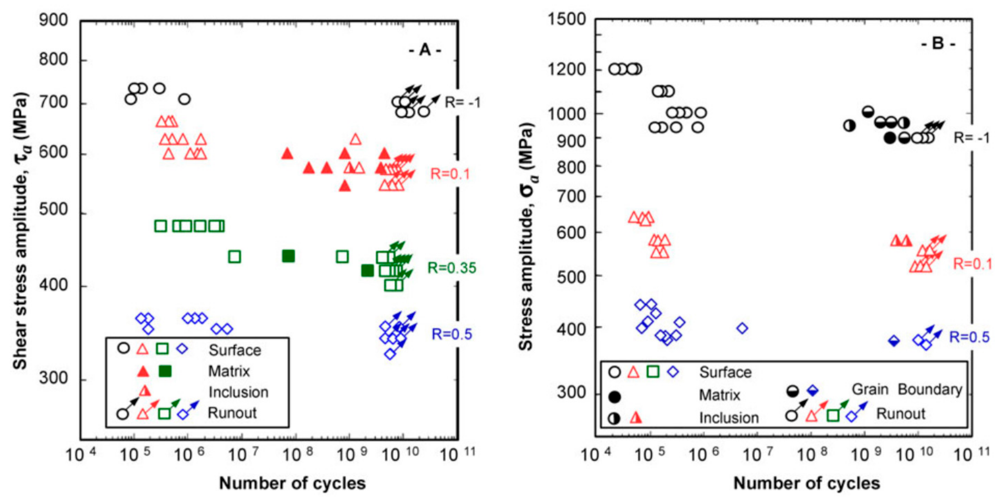
Figure 1. S-N data for shot peened spring steel [54] (A) for torsion, (B) for tension.
Applsci 10 08475 g001
Figure 2. Stress intensity factors of crack-initiating defects (white and grey symbols), as well as the stress intensity factors on the border of the fine granular area (FGA) (blue symbols) [91].
Applsci 10 08475 g002
Figure 3. Ion-induced secondary electron images of serial cuts inside the FGA (cut distance 0.2 µm) generated by FIB (ϭa = 875 MPa, Nf = 7.71 × 10⁵) increasing cutting depth from upper left to lower left and upper right to lower right [13].
Applsci 10 08475 g003
Figure 4. (a) ISE image of a TiN inclusion with FGA crack and length measurements corresponding to the thickness evaluation positions in enlarged views in (b) and (c) [90].
Applsci 10 08475 g004
Figure 5. Measured FGA thickness tFGA in comparison to the plastic zone size (plane strain) perpendicular to the crack plane rpy calculated by different plastic zone size models [90].
Applsci 10 08475 g005
Figure 6. (a,b) SEM images of the cross-section samples cut along the loading direction in the “tree ring” region of a specimen failed at a total fatigue life of 8.567 × 10⁷ under variable amplitude loading ( σ a H = 650 MPa, nH = 4 × 10³, σ a H = 430 MPa, nL = 3 × 10⁶), (c) EBSD image of the rectangle region in (b) with a scanning step of 10nm for the enlarged EBSD image in the green rectangle, 40nm for the upper part and 65 nm for the lower part of the large EBSD image [88].
Applsci 10 08475 g006
Figure 7. (a) SEM image of the crack tip and the mated crack surface for the specimen after compressive fatigue test on a preciously introduced crack; (b) EBSD inverse pole figure maps for the rectangle region in (a) [104].
Applsci 10 08475 g007
Figure 8. (a) Indexing confidence map of the analyzed area around a VHCF crack given by a dashed red line with FGA; (b) IPF-Map of the analyzed microstructure along the crack; (c) reconstructed grains boundary image of the microstructure, based on the reliably indexed grains from the IPF-Map in (b) [91].
Applsci 10 08475 g008
Figure 9. Map of the highest Schmid factors for the sliding system {110}/<1–11> and the traces of the {110} sliding planes in the areas 0 to 9, whereby the planes with the highest Schmid factor are marked in red and labelled with the corresponding values [91].
Applsci 10 08475 g009
Publisher’s Note: MDPI stays neutral with regard to jurisdictional claims in published maps and institutional affiliations.