1. Introduction
Various approaches are used to design centrifugal compressors for engine turbochargers, including engineering techniques and Computational Fluid Dynamics (CFD) software. The aim of the work is to make a high effective turbocharger, to check the design instrument (the Universal Modeling Method) and CFD modeling validity. There are different opinions on the last issue.
In the paper [
1], modeling of three centrifugal turbochargers for internal combustion engines is considered. The aim of the work [
1] was to improve the mean line modeling. Mean line of characteristics modeling and CFD modeling were presented against test data. For the calculations, the ANSYS CFX 14 program was used, the computational mesh of objects consisted of 1.6 million cells (the number of cells was obtained as a result of a study of mesh independence). The flow in the gap “impeller hub disk—wall” is not modeled. Disk friction losses are omitted in the calculation. The calculations were corrected for the amount of disc friction losses according to the model [
2]. Scroll losses were calculated using the model [
3].
For turbochargers C-1 and C-3, good agreement was obtained between the calculated and measured efficiency, both in magnitude and in the area of operation at the design rpm. For the C-2 turbocharger, a shift of the calculated characteristic towards lower flow rates compared to the measured one is observed. For all compressors, there is an overestimation of the calculated efficiency over the measured one at low rpm. The authors explain the discrepancy between the calculated and experimental data by the fact that CFD calculations were carried out without taking heat supply into account, while during the tests there was a heat flux from the turbine.
As a continuation of the research [
1], the paper [
4] was published. It investigated two other turbochargers. For calculations with a reduced rpm, a shift of the calculated characteristics towards higher flow rates is noticeable, while, as the rated power is approached, the zones of the measured and calculated characteristics coincide better. The calculated maximum stage efficiency also exceeds the measured one by about 6%.
The authors of Ref. [
5] also calculated the internal combustion engine turbocharger. The Star-CCM+ program was used for the numerical study. An analysis of more than 15 different works carried out by the authors allowed to draw the following conclusions on the choice of a turbulence model for various CFD programs: for ANSYS CFX, the Shear Stress Transport (SST) turbulence model gives the best results, for Numeca FINE/Turbo the SA turbulence model is more preferable, for Star-CCM +, the
one. The calculation is performed in a stationary setting without taking into account the heat input. To achieve grid independence, the authors considered four computational grids with the number of cells from 27 to 84.4 million. The comparison was made for two modes: design rpm and about half of design rpm. The calculated and test characteristics are in good agreement both in magnitude and in the area of operation. In this case, good agreement is also achieved at reduced rpms, for which the authors of [
1] obtained a significant discrepancy between the calculated and experimental data, explained by not taking into account the heat supply in CFD calculations.
Such a discrepancy in the results of CFD calculations with practically the same formulation (in both cases, the process was considered adiabatic during calculations) shows that it is difficult to speak about the reliability and repeatability of CFD calculations without their preliminary comprehensive identification.
The authors of [
6] investigated a new geometry generator that was developed for the design of curvature-smooth blades (vanes). The blade cascade can be initially designed by a conventional way and then smoothed. The flow was simulated in a stage 3D impeller + vaneless diffuser (VLD) of a turbocharger. The computational grid was built for one channel; the total number of cells was 2.3 million. The SST turbulence model and the ANSYS CFX program were used. Calculated and test data comparison demonstrated significant overestimation of the calculated pressure ratio and a shift of the calculated characteristics to the right, which is typical for a number of other comparisons of CFD calculations with experiments [
7,
8,
9,
10,
11,
12,
13,
14,
15,
16,
17,
18,
19,
20]. We can also observe unusually large overestimation of calculated efficiency.
Obviously, CFD calculations of engine turbochargers (like other centrifugal compressors) cannot yet replace engineering design and calculation methods.
The aim of the research is to design a centrifugal compressor for an 8ChN26/26 gas engine, measure its gas-dynamic characteristics at four different rpm, check the compliance of the CFD-calculated gas-dynamic characteristics of a centrifugal compressor of an internal combustion engine turbocharger with the characteristics obtained on the test rig.
2. Materials and Methods
One of the largest manufacturers of turbochargers for internal combustion engines for various purposes in Russia is RPA “Turbotekhnika”. One of the current topical works is the turbocharger for the 8ChN26/26 gas engine, converted from a diesel engine. Preliminary calculations showed that the maximum degree of boost should not exceed 1.6–1.7. This requires the largest possible range of blower performance.
The Laboratory “Gas Dynamics of Turbomachines” currently represents the scientific school of compressor engineering of Peter the Great St. Petersburg Polytechnic University (SPbPU), founded in 1960s [
21]. The laboratory has extensive experience in the design of centrifugal compressors for various purposes [
21,
22,
23]. It has at its disposal specialized engineering programs for the calculation and design of centrifugal compressors, called the Universal Modeling Method. The authors work on the Method improving [
24,
25,
26].
Employees of Laboratory of Gas Dynamics Turbomachines (LGDTM) made an optimal design of the impeller, taking into account the standard dimensions of the diffuser and the scroll of the radial turbocharger TKR-140 turbocharger and calculated its gas-dynamic characteristics in the speed range. The employees of RPA “Turbotekhnika” designed, manufactured and tested a turbocharger at their experimental test rig.
3. Results
3.1. Design of a Centrifugal Compressor TKR 140E
Compressor design parameters:
= 0.62 kg/s,
= 1.61. The turbocharger TKR 140E is for a transport diesel engine converted to gas. It is important to achieve a wide range of flow rates. At a set turbine rpm, the first question of the variant calculation is the choice of the impeller diameter. The variant calculation and preliminary design program calculated the efficiency of each variant using a simplified mathematical model that summarizes the results of the optimal design of 2000 stages [
27,
28]. The system of algebraic equations for calculating efficiency is
. Here
—flow coefficient,
—loading factor,
—hub ratio,
-similarity criteria’s. The program PDCC-G8E serves for a preliminary analysis and uses ideal gas equations.
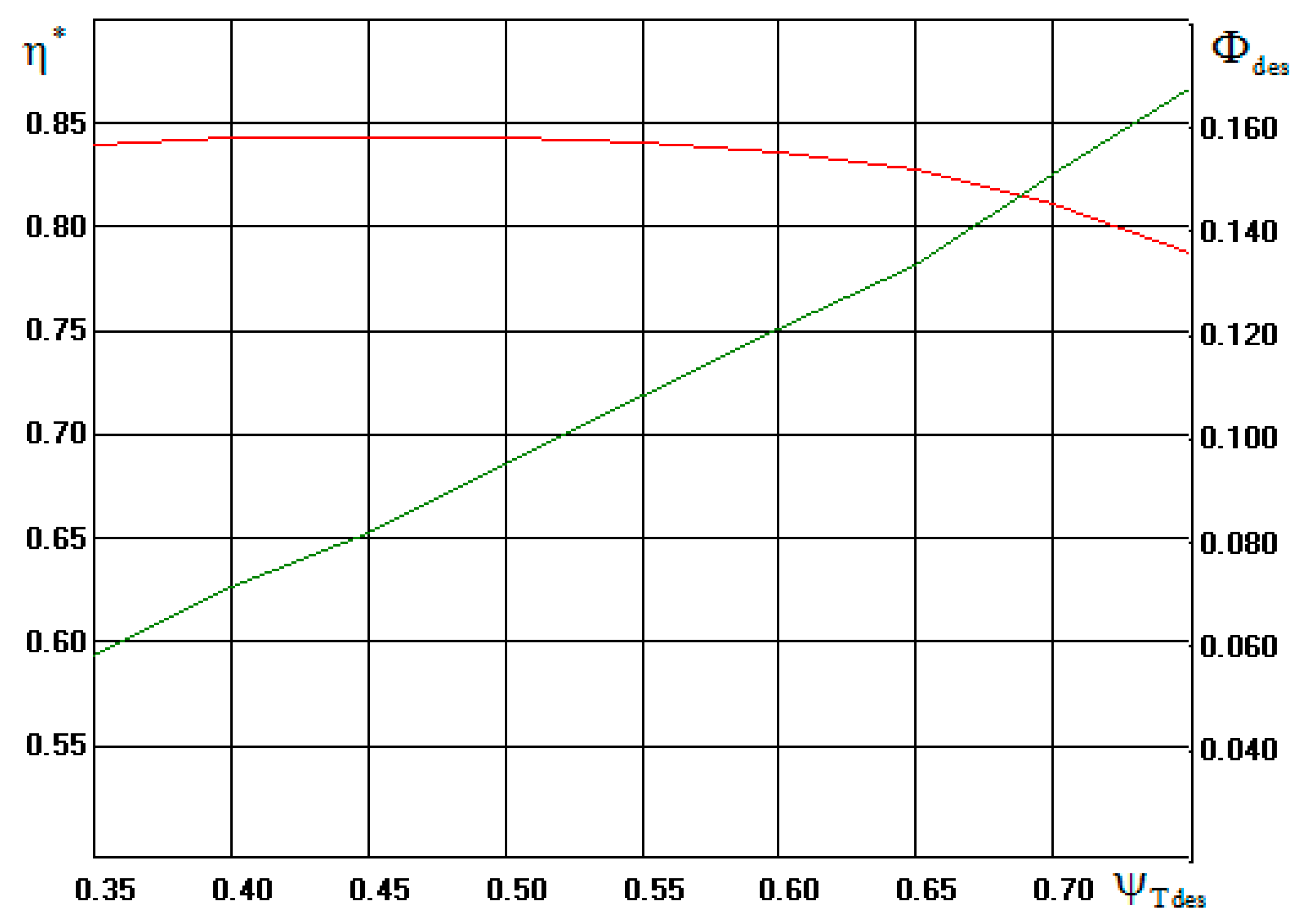
Figure 1 shows the dependence of the efficiency and flow rate for the TKR 140E compressor variants at different loading factors.
The highest efficiency was achieved for the variant with
0.47. For a medium-speed engine with a very long service life, an impeller with its peripheral speed as low as possible is preferred. In order to limit the peripheral speed, we chose the variant with a loading factor higher than the optimal one, namely
= 0.572. This variant has a peripheral speed of 300 m/s, but according to a variant calculation, the efficiency is 0.43% lower than that of the optimal one. The main parameters of the calculated and selected variants are presented in
Figure 2.
For the selected variant, the PDCC-G8E program performed a preliminary design of the flow path according to an algorithm developed on the basis of special researches [
27,
28].
Figure 3 shows the characteristics of a TKR 140E compressor with a flow path before it was optimized.
The graphs show how the total pressure ratio , polytrophic efficiency and power consumption N (kW) varied with mass flow (kg/s). According to the preliminary design, the compressor efficiency at a design mass flow of 0.62 kg/s is 0.80. The maximum efficiency was 0.842 at a flow rate of 0.44 kg/s. Obviously, when optimizing the flow path, this drawback should be eliminated.
Qualitative optimization of the impeller was based on the analysis of the velocity diagrams of the quasi-three-dimensional compressible inviscid flow. The 3DM.023 program calculated the meridional flow by the quasi-orthogonal method. On axisymmetric stream lines, the calculation was performed by the method of integral equations. The advantage of the method was the calculation of the flow around the leading and trailing edges of the blades, which is impossible when calculating by the mesh method.
Velocity diagrams on the shroud streamline in the impeller according to the preliminary design and after optimization are shown in
Figure 4.
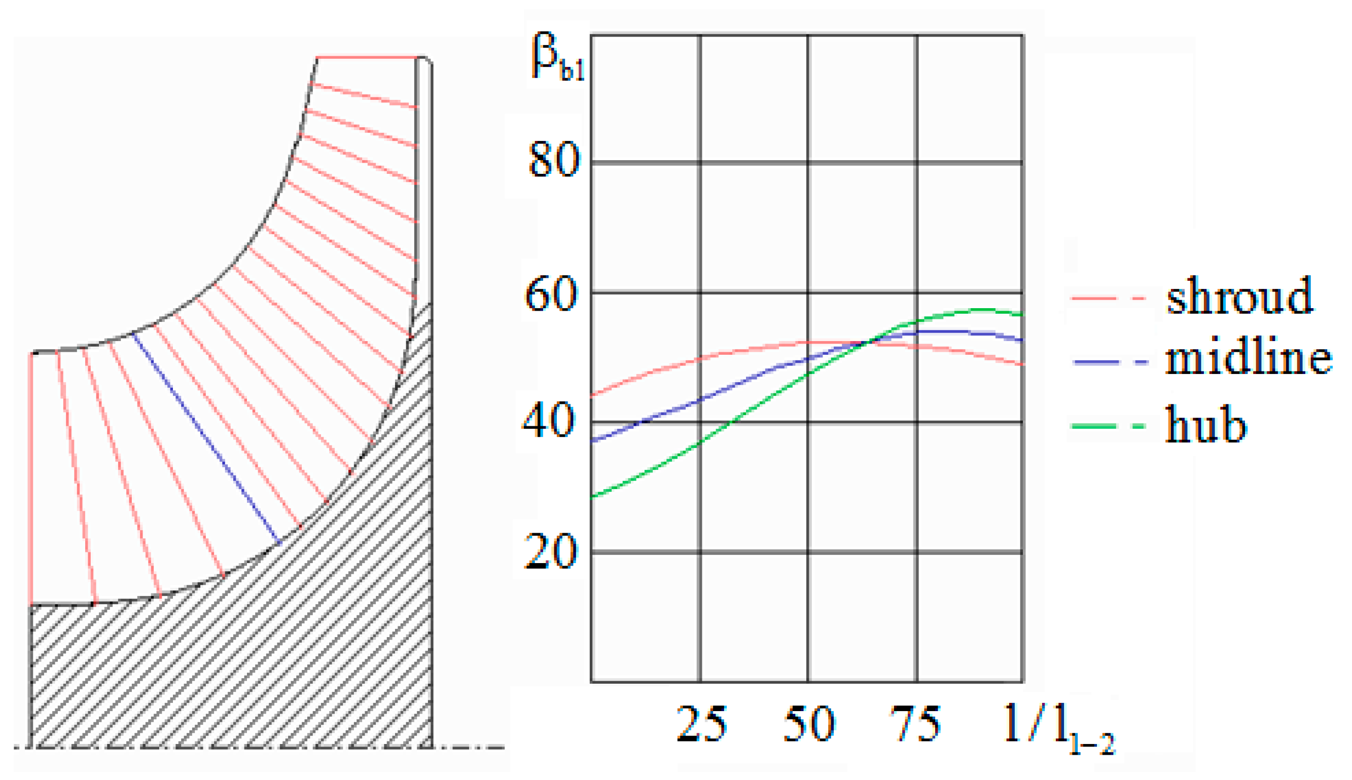
According to the preliminary design, the dimensions of the inlet to the impeller were insufficient. The stream entered with a negative incidence angle, which reduced efficiency. After optimization, this and other shortcomings were eliminated. In accordance with the recommendations [
29,
30], the outlet angle of the blades
increased from the hub to the shroud. According to the recommendations [
31], the trailing edge was inclined in the direction of rotation. Negative bulk angle is
= −15°. The shape of the blades centerline
was adopted with a double curvature, this was necessary to eliminate the “saddle” in the velocity diagram on the shroud streamline. The diagram of the final version of the 3D impeller in the meridional plane and the blade angles are shown in
Figure 5.
The final version of the TKR 140E compressor impeller was coordinated with the dimensions of the standard TKR 140 compressor designed by RPA “Turbotekhnika”.
3.2. Comparison of Experimental and Design Characteristics of TKR 140E
RPA “Turbotekhnika” manufactured and tested two versions of TKR 140E. In the housing of a standard TKR 140, an impeller was installed according to the project of the Gas Dynamics of Turbomachines laboratory, presented above, with a diameter of 175 mm (TKR 175E). TKR 175E tests were preliminary, aiming to check the loading factor characteristics.
The basic version of the TKR 140E had an impeller designed by the Gas Dynamics of Turbomachines laboratory with a diameter of 140 mm with stator elements of the appropriate size. A meridional section of the TKR 140E turbocharger is shown in
Figure 6.
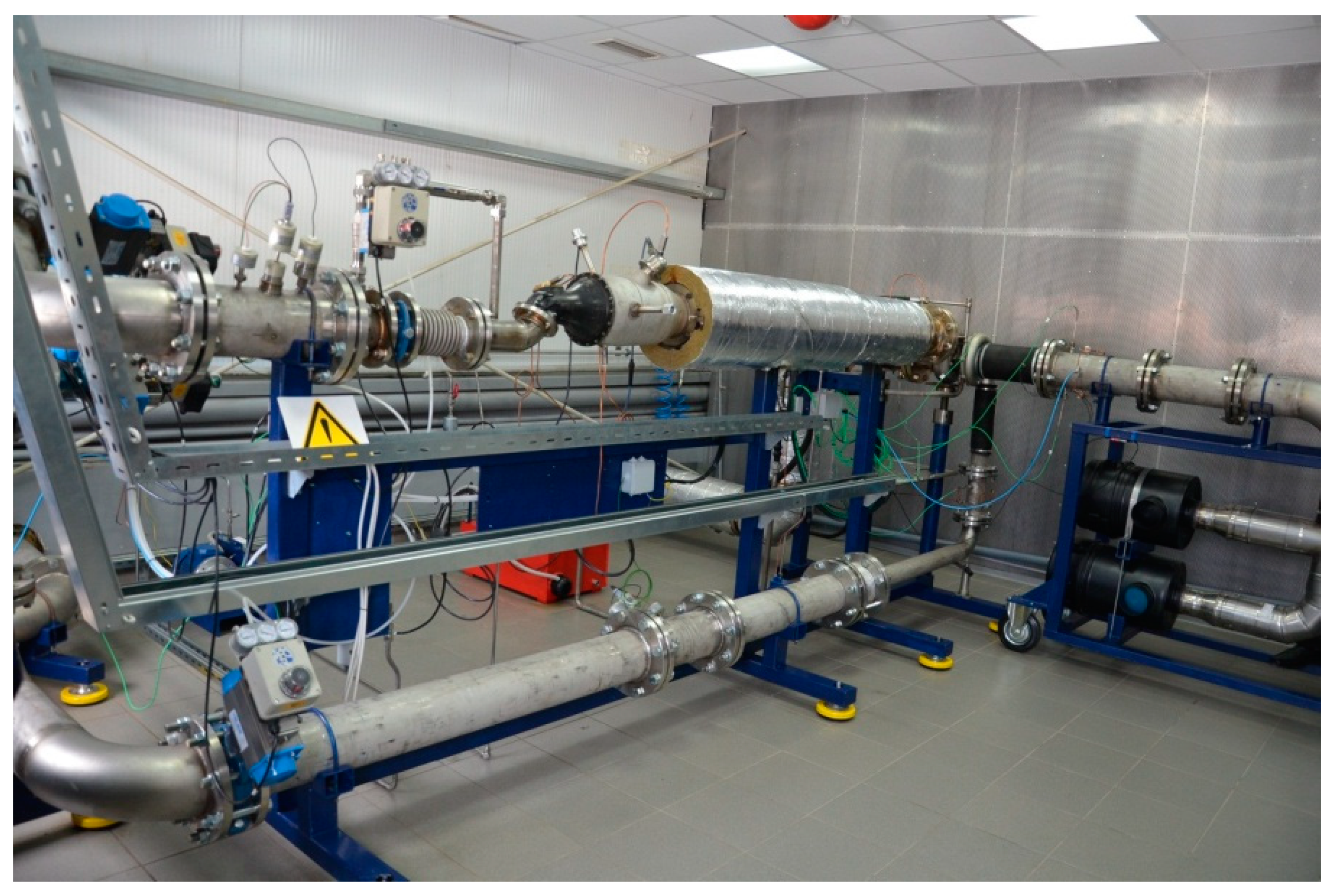
The compressors were tested at the test rig of RPA “Turbotekhnika”, shown in
Figure 7.
The TKR-175E compressor was tested with the stator elements of a standard TKR-140 with a VLD and a scroll that were of insufficient dimensions. The TKR-175E compressor view is shown in
Figure 8.
TKR 175E test confirmed the design characteristic of the work coefficient. However, the characteristics of the efficiency and the polytropic work coefficient were not satisfactory at medium and high flow rates due to the discrepancy between the passage sections of the impeller and the stator elements.
For the TKR-140E compressor, the dimensions of the impeller and stator elements corresponded to each other. The calculated and measured gas-dynamic characteristics of the TKR-140E compressor are shown in
Figure 9. The tests were carried out at
= 0.437, 0.5836, 0.7280, 0.8739.
At the design flow rate = 0.62 kg/s at the design blade velocity = 300 m/s, the design pressure ratio almost perfectly matched its predicted value. The expected efficiency was been confirmed. The mathematical model slightly overestimated the efficiency and the pressure ratio in off-design modes. The mathematical model calculated the efficiency in the design mode for all tests with an error of 0.89%, and the efficiency for the entire characteristic with an error of 1.55%.
3.3. CFD Calculations
The cumulative experience of the authors [
32,
33,
34] showed that CFD calculations of centrifugal compressor stages and industrial centrifugal compressors, single-stage and multi-stage, showed approximately similar results: the efficiency characteristic was shifted towards higher flow and the loading factor was overestimated at the same time. The authors investigated the influence of different calculation methods:
- -
Stationary or unsteady flow.
- -
Interface type, (“stage”, “frozen rotor”).
- -
Turbulence model.
- -
Computational grid, etc.
Typical examples of comparing calculated and experimental data are shown in
Figure 10.
The 16 Mw two-stage compressor (
Figure 10b) was modeled with gaps “impeller shroud disk—wall” and “impeller hub disk—wall” (“CFD (gaps)” in
Figure 10) and by a simplified way (“CFD (no gaps)”). The test was a plant test in air.
As a result, recommendations were developed as to which formulation of the calculation gives the best result; however, even then it did not meet the requirements of practical engineering applicability. The authors of the paper applied all their previous experience in CFD calculations in order to determine whether the calculation of a centrifugal compressor of an internal combustion engine turbocharger would show better results compared to those obtained earlier.
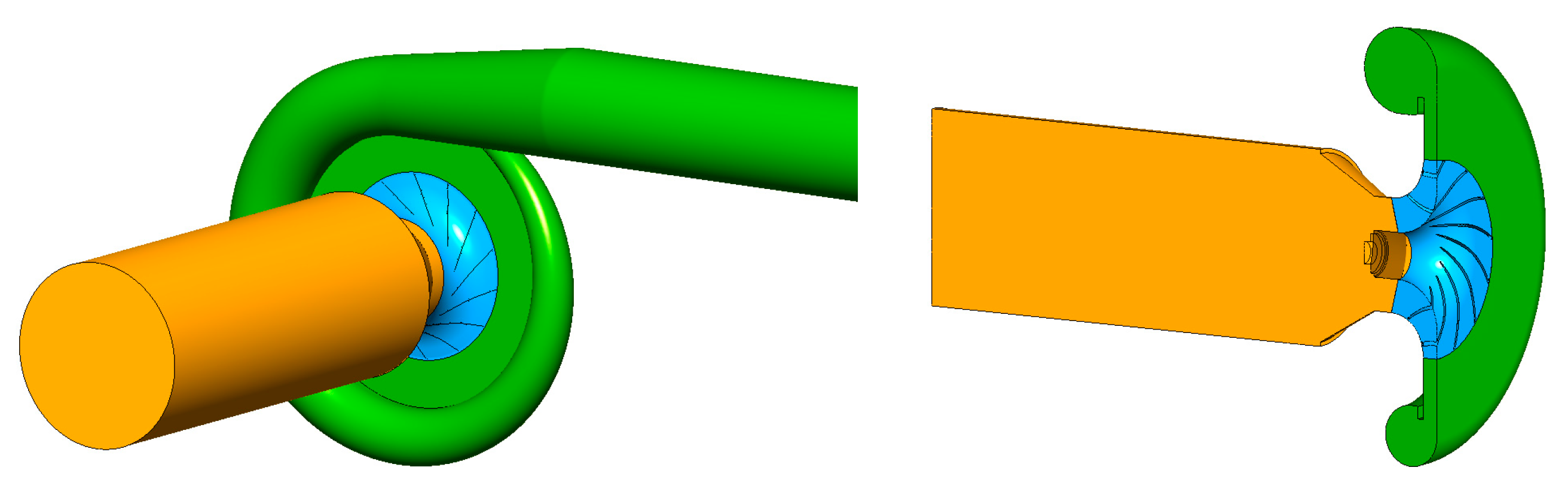
Since the TKR-175E tests were of a preliminary nature, its gas-dynamic characteristics were not modeled. The object of the research was the TKR 140E compressor, calculated together with the inlet nozzle and a part of the pipeline behind the scroll. The geometric model is shown in
Figure 11.
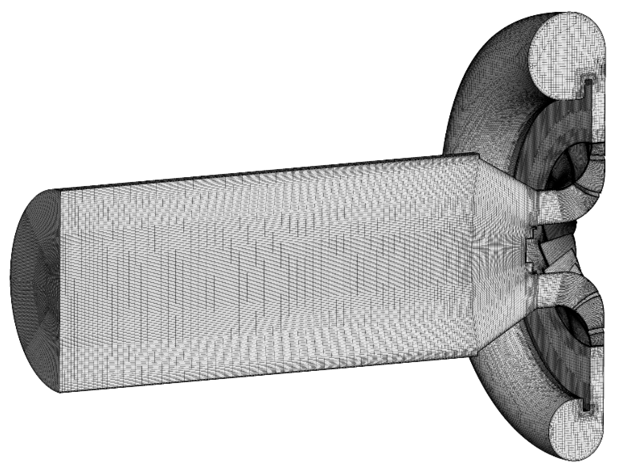
The ANSYS/CFX numerical simulation system was used to calculate the gas dynamic characteristics of the compressor. The computational model was built in the form of a finite number of computational cells that describe the flow path geometrically with a set degree of discretization. The grid model of the flow path of the model stage is shown in
Figure 12.
The mesh model used a structured hexagonal grid for the inlet, impeller and diffuser, and an unstructured hybrid mesh for the scroll. To take into account the boundary layer, the thickening necessary to meet the requirements of turbulence models and near-wall functions was set to the boundaries defining the walls of the flow path. The size of the first parietal cell varied in the range of 10–50 microns. The enlargement factor was 1.2–1.5. The total number of cells was ~14,886,000.
To provide numerical simulation, the computational domain was divided into three domains: an inlet nozzle, an impeller, and a diffuser with a scroll. In this case, for the inlet nozzle and diffuser with a scroll, the equations were solved in a static coordinate system, while for the impeller, the equations were written in a rotating coordinate system. To match the gas-dynamic parameters at the boundary between the impeller and the diffuser, special interface conditions of the “stage” type were used, which assumed averaging the flow parameters along the circumferential direction at the boundary with the region located upstream. The total pressure and temperature were set at the inlet nozzle as boundary conditions for all design cases. The mass flow rate was set at the outlet boundary. The walls were considered adiabatic. The calculation was performed assuming a steady flow regime.
CFD calculations were done for three rpm:
= 20,760, 27,900 and 41,400.
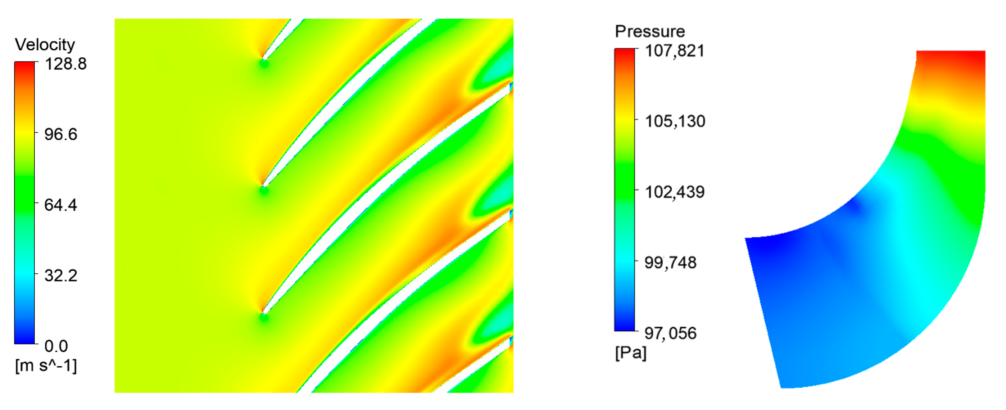
Figure 13 shows the velocity and pressure in the impeller at the maximum efficiency mode at
n = 20,760 rpm on the midline streamline.
The calculated picture corresponded to the idea of gas movement in impellers of this type. Judging by the small zone of increased velocity on the suction side near the leading edge, there was a small positive incidence angle at the optimum flow rate. Despite the developed stall zone at the impeller outlet, the measured efficiency was quite high for a small compressor.
4. Discussion
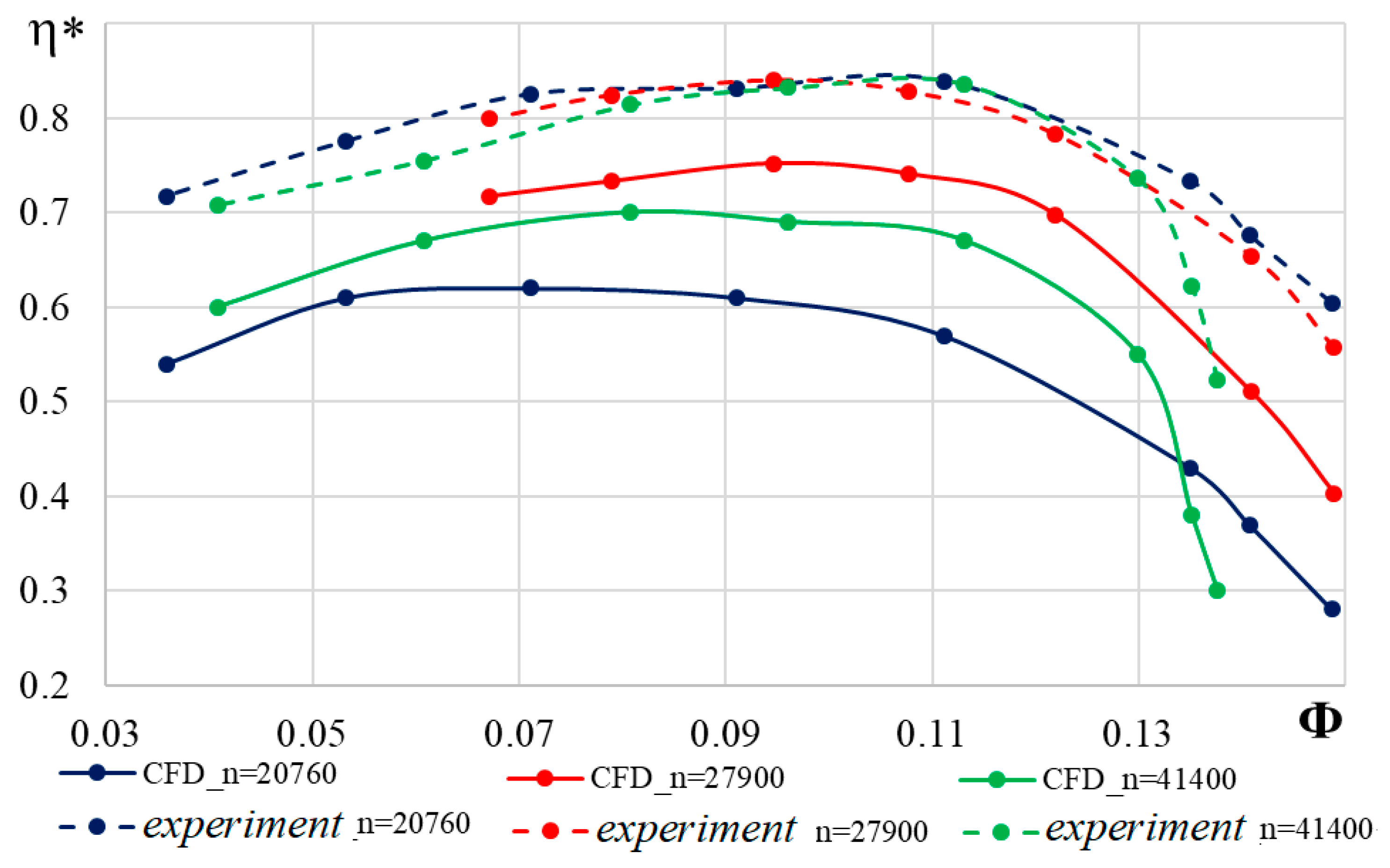
Comparison of the calculated and measured gas dynamic characteristics showed the following: as in other similar cases, CFD calculation overestimated the work coefficient by 10–12%. The efficiency characteristics are shown in
Figure 14.
In contrast to the calculated characteristics of other compressors [
32,
33,
34], in this case the measured and calculated characteristics lie in approximately the same flow rate range. Unusually, the calculated efficiency is much lower than the measured one, especially at
= 20,760 rpm.
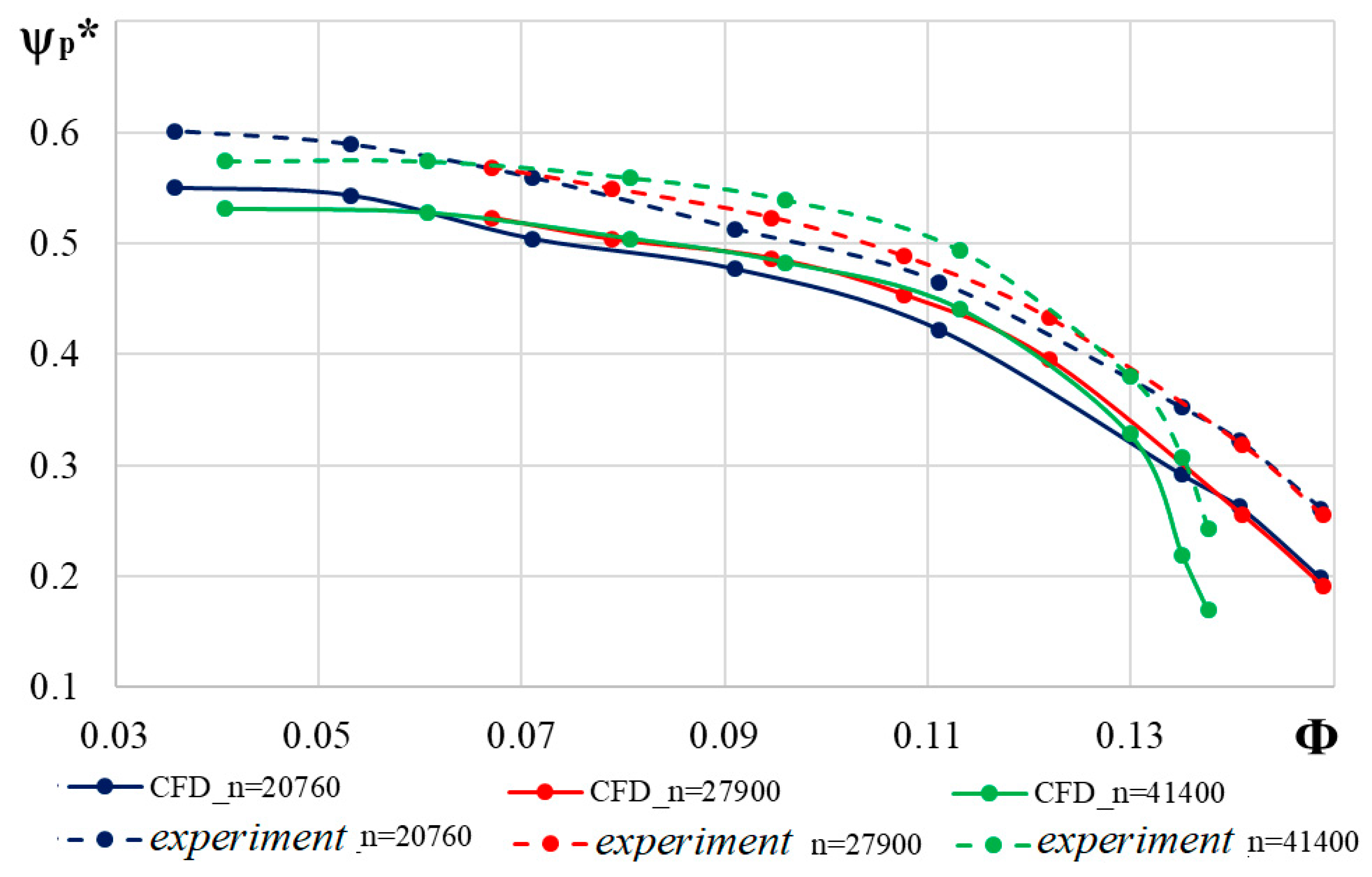
In cases where the measured efficiency is lower than calculated one, the measured efficiency is considered questionable. This is due to the fact that measurements of the internal head based on the increase in the gas temperature in the compressor can be associated with errors. It is more reliable to measure the pressure ratio, according to which the polytropic work coefficient is calculated,
Figure 15.
In this case, the calculated characteristics are more logical. The more rpm, the higher the polytropic work coefficient. This is a well-known manifestation of gas compressibility. Despite the fact that, according to the calculation, the work coefficient (the coefficient characterizing the mechanical work supplied to the gas) is greater than the measured one, the calculated efficiency is less than the probably correctly measured value of . The measured efficiency can be trusted.
5. Conclusions
The research has shown once again that CFD calculations are not yet a reliable means of calculating the characteristics of compressors. Engineering methods, Universal Modeling and the like are still irreplaceable and deserve attention and improvement. The main ideas of the method were presented still in 1980th [
25]. The conference reports [
35,
36,
37,
38] present details of the state. The main features of the head loss model:
- -
Head loss of a stage is a sum of inlet nozzle, impeller, diffuser, return channel or outlet nozzle.
- -
Inside blade or vane cascade head loss is a sum of losses on suction and pressure side of a profile, on a shroud and on a hub.
- -
Head loss is a sum of surface friction (secondary losses are included) and separation losses, i.e., mixing or pressure losses.
- -
Incidence losses are added at off-design flow rates.
- -
Similarity criteria M, Re, k are taken into account and a surface roughness as well.
Algebraic equations are developed for each component of losses. In the last version of the Method, algebraic equations includes 64 empirical coefficients that need identification. The identification is made by test characteristics of dozens of model stages.
The important difference of the method with the well-known Concept Agile engineering [
39,
40,
41,
42,
43] was discussed with its author Dr. D. Japikse during his visit to The Leningrad Polytechnic Institute in the end of 1980th. The main differences are:
- -
The Concept loss model operates with parameters of the boundary lay theory. The method calculates loss coefficients and drag force coefficients.
- -
The Concept loss model is identified by test characteristics of a stage elements (impeller, diffuser, etc.). The Method loss model is identified by test characteristics of a whole stage.
The difference of engineering models does not mean that one is valid and the other is wrong. Different models could be effective in engineering applications. In this case, the Universal Modeling Method has confirmed its effectiveness and made it possible to create an efficient turbocharger compressor and accurately calculate its characteristics in the required rpm range.
Author Contributions
Conceptualization, Y.G. and A.D.; methodology, Y.G. and O.S.; software, A.D., A.B. and I.V.; validation, R.K. and K.S. All authors have read and agreed to the published version of the manuscript.
Funding
This research was funded by open access charge: Russian Academic Excellence Project 5-100.
Acknowledgments
The calculations were performed using the supercomputer center SCC “Polytechnic”.
Conflicts of Interest
The authors declare no conflict of interest.
References
- Harley, P.; Spence, S.; Filsinger, D.; Dietrich, M.; Early, J. Meanline modeling of inlet recirculation in automotive turbocharger centrifugal compressors. J. Turbomach. 2015, 137, 011007. [Google Scholar] [CrossRef]
- Aungier, R.H. Centrifugal Compressors: A Stragedy for Aerodynamic Design and Analysis; ASME Press: New York, NY, USA, 2000; p. 320. [Google Scholar]
- Weber, C.R.; Koronowski, M.E. Meanline Performance Prediction of Volutes in Centrifugal Compressors. In Proceedings of the ASME Turbo Expo 1986, Dusseldorf, Germany, 1986; American Society of Mechanical Engineers: New York, NY, USA, 2014. V001T01A091. [Google Scholar] [CrossRef]
- Harley, P.; Spence, S.; Filsinger, D.; Dietrich, M.; Early, J. Experimental and numerical benchmarking of an improved meanline modelling method for automotive turbocharger centrifugal compressors. In Proceedings of the ASME Turbo Expo 2015, Montréal, QC, Canada, 15–19 June 2015. [Google Scholar]
- Abel, M.; Newton, P.; Martinez-Botas, R.F.; Wohr, M.; Muller, M.; Leweux, J. 3D computational analysis of a compressor for heavy duty truck engine turbochargers. In Proceedings of the ASME Turbo Expo 2018: Turbomachinery Technical Conference and Exposition, Oslo, Norway, 11–15 June 2018. [Google Scholar]
- Bi, Q.; Chen, H.; Tong, D.; Lu, Y.; Zou, X. Design method and performance effects of curvature-smooth centrifugal compressor blades. In Proceedings of the ASME Turbo Expo 2015: Turbomachinery Technical Conference and Exposition, Montréal, QC, Canada, 15–19 June 2015. GT2015-43145. [Google Scholar]
- Kabalyk, K.; Kryłłowicz, W. Numerical modeling of the performance of a centrifugal compressor impeller with low inlet flow coefficient. Trans. Inst. Fluid Flow Mach. 2016, 131, 41–53. [Google Scholar]
- Kryłłowicz, W.; Świder, P.; Kozanecki, Z.; Kabalyk, K.; Kozanecki, Z., Jr. Technical and Aerodynamical Aspects of a High Pressure Synthesis Gas Turbocompressor Modernization. In Proceedings of the 12th European Conference on Turbomachinery Fluid Dynamics and Thermodynamics, Stockholm, Sweden, 3–7 April 2017. [Google Scholar]
- Marechale, R.; Ji, M.; Cave, M. Experimental and numerical investigation of labyrinth seal clearance impact on centrifugal impeller performance. In Proceedings of the ASME Turbo Expo 2015: Turbine Technical Conference and Exposition GT2015, Montréal, QC, Canada, 15–19 June 2015. GT2015-43778. [Google Scholar]
- Matas, R.; Syka, T.; Lunacek, O. Numerical and experimental modelling of the centrifugal compressor stage—setting the model of impellers with 2D blades. In Proceedings of the EPJ Web of Conferences 11th International Conference on Experimental Fluid Mechanics 2017, Mikulov, Czech Republic, 12 May 2017; Volume 143, p. 02073. [Google Scholar]
- Hazby, H.; Casey, M.; Robinson, C.; Spataro, R. The design of a family of process compressor stages. In Proceedings of the 12th European Conference on Turbomachinery Fluid dynamics & Thermodynamics ETC12 2017, Stockholm, Sweden, 3–7 April 2017. Paper ID: ETC2017-134. [Google Scholar]
- Matas, R.; Syka, T.; Hurda, L. Experimental investigation and numerical modelling of 3D radial compressor stage and influence of the technological holes on the working characteristics. EPJ Web Conf. 2018, 180, 02060. [Google Scholar] [CrossRef][Green Version]
- Syka, T.; Matas, R.; Luňáček, O. Numerical and experimental modelling of the radial compressor stage. AIP Conf. Proc. 2016, 1745, 020059. [Google Scholar]
- Sausse, P.L.; Fabrie, P.; Arnou, D.; Clunet, F. CFD comparison with centrifugal compressor measurements on a wide operating range. EPJ Web Conf. 2013, 45, 01059. [Google Scholar] [CrossRef]
- Xinqian, Z.; Meijie, Z. Criteria for the Matching of Inlet and Outlet Distortions in Centrifugal Compressors. Appl. Therm. Eng. 2018, 131, 933–946. [Google Scholar]
- Elfert, M.; Weber, A.; Wittrock, D.; Peters, A.; Voss, C.; Nicke, E. Experimental and numerical verification of an optimization of a fast rotating high performance radial compressor impeller. In Proceedings of the ASME Turbo Expo 2016: Turbomachinery Technical Conference and Exposition 2016, Seoul, Korea, 13–17 June 2016. GT2016-56546. [Google Scholar]
- Kowalski, S.C.; Pacheco, J.E.; Fakhri, S.; Sorokes, J.M. Centrifugal stage performance prediction and validation for high mach number applications. In Proceedings of the Forty-First Turbomachinery Symposium 2012, Houston, TX, USA, 24–27 September 2012. [Google Scholar]
- Shahin, I.; Gadala, M.; Alqaradawi, M.; Badr, O. Unsteady CFD simulation for high speed centrifugal compressor operating near surge. In Proceedings of the ASME Turbo Expo 2014: Turbine Technical Conference and Exposition 2014, Düsseldorf, Germany, 16–20 June 2014. GT2014-27336. [Google Scholar]
- Bourgeois, J.A.; Nichols, J.C.; Watson, G.H.; Martinuzzi, R.J. Single passage detached eddy simulation of a centrifugal compressor stage using the time transformation method. In Proceedings of the ASME Turbo Expo 2015: Turbine Technical Conference and Exposition 2015, Montréal, QC, Canada, 15–19 June 2015. GT2015-44131. [Google Scholar]
- Dombard, J.; Duchaine, F.; Gicquel, L.; Staffelbach, G.; Buffaz, N.; Trebinjac, I. Large eddy simulations in a transonic centrifugal compressor. In Proceedings of the ASME Turbo Expo 2018 Turbomachinery Technical Conference and Exposition GT2018 2018, Oslo, Norway, 11–15 June 2018. [Google Scholar]
- Galerkin, Y.B. (Ed.) Proceedings of the Scientific School of Compressor Engineering SPbSTU. [Text]; Publishing House of Scientific and Technical Information Center, SPbSTU: Saint-Petersburg, Russia, 2010. [Google Scholar]
- Vasiliev, Y.S. New Generation High Performance Centrifugal Compressors. Scientific Principles of Calculation, Development of Optimal Design Methods and Production Development; Yu, S., Vasiliev, P.I., Rodionov, P.I., Sokolovsky, M.I., Eds.; Science and Industry of Russia: Moscow, Russia, 2000; No. 10–11; pp. 78–85. [Google Scholar]
- Galerkin, Y.B. Turbocompressors. Workflow, Calculation and Design of the Flow Path; LLC "Information and Publishing Center" KHT: Moscow, Russia, 2010; p. 596. [Google Scholar]
- Galerkin, Y.B.; Soldatova, K.V. Modeling the Workflow of Industrial Centrifugal Compressors. Scientific Foundations, Stages of Development, Current State; Monograph; Publishing House of the Polytechnic University: Moscow, Russia, 2011; p. 327. [Google Scholar]
- Seleznev, K.P.; Galerkin, Y.B. Mathematical Modelling of Performance Characteristics and Optimization of Turbomachine Stades. In Proceedings of the International Gas Turbine Congress, Tokyo, Japan, 17–22 November 1983. [Google Scholar]
- Rekstin, A.F.; Drozdov, A.A.; Solovyeva, O.A.; Galerkin, Y.B. Two mathematical models centrifugal compressor stage vaneless diffuser comparison. In Proceedings of the Oil and Gas Engineering (OGE-2018), AIP Conf. Proc. 2007, Omsk, Russia, 26 February–2 March 2018; Volume 2007, pp. 030035-1–030035-12. [Google Scholar] [CrossRef]
- Rekstin, A.F.; Soldatova, K.V.; Galerkin, Y.B. Experience of application the computer program based on a simplified mathematical model for industrial centrifugal compressors candidates. Int. Conf. Compress. Syst. IOP Conf. Ser. Mater. Sci. Eng. 2019, 604, 012045. [Google Scholar] [CrossRef]
- Rekstin, A.; Popova, Y.; Ucehovscy, A. Centrifugal compressor stages efficiency analysis by means of the approximate algebraic equations. In Proceedings of the Oil and Gas Engineering (OGE-2018), AIP Conf. Proc. 2007, Omsk, Russia, 26 February–2 March 2018; Volume 2007, pp. 030036-1–030036-11. [Google Scholar] [CrossRef]
- Galerkin, Y.; Drozdov, A.U. Centrifugal compressor stage design principles checking. In Proceedings of the ASME Gas Turbine India Conference, Hyderabad, India, 2–3 December 2015. GTINDIA2015-1202. [Google Scholar]
- Galerkin, Y.B.; Drozdov, A.A. Design and optimization of a centrifugal compressor stage with an 3D impeller using an engineering design method. Sci. Tech. Statements SPbPU 2015, 231, 179–188. [Google Scholar]
- Drozdov, A.A. Design Method for Centrifugal Compressors with 3D Impellers; Drozdov, A.A., Ed.; Ph.D. Thesis–SpbPU: Saint-Petersburg, Russia, 2016; p. 236. [Google Scholar]
- Borovkov, A.I.; Voinov, I.B.; Galerkin, Y.B.; Nikiforov, A.G.; Nikitin, M.A. Issues of Modeling Gas-dynamic Characteristics on the Example of a Model Stage of a Centrifugal Compressor; Scientific and Technical Statements SpbPU: Saint-Petersburg, Russia, 2018; Volume 24, No. 2; pp. 44–57. [Google Scholar] [CrossRef]
- Borovkov, A.I.; Voinov, I.B.; Rekstin, A.F.; Bakaev, B.V. Modeling the Characteristics of a Two-stage Pipeline Centrifugal Compressor; Scientific and Technical Statements SpbPU: Saint-Petersburg, Russia, 2019; Volume 25, No. 2; pp. 87–104. [Google Scholar] [CrossRef]
- Borovkov, A.I.; Voinov, I.B.; Nikitin, M.A.; Galerkin, Y.B.; Rekstin, A.F.; Drozdov, A.A. Modeling the Characteristics of a Single-stage Pipeline Centrifugal Compressor; Natural and Engineering Sciences; Scientific and Technical Statements of SpbPU: Saint-Petersburg, Russia, 2018; Volume 24, No. 3; pp. 153–175. [Google Scholar] [CrossRef]
- Galerkin, Y.B.; Danilov, K.A.; Popova, E.Y. Universal Modelling for Centrifugal Compressors-Gas Dynamic Design and Optimization Consepts and Application. In Proceedings of the Yokohama International Gas Turbine Congress, Yokohama, Japan, 22–27 October 1995. [Google Scholar]
- Galerkin, Y.B.; Mitrofanov, V.P. Current Optimum Design Methods in the Development of New Generations of Model Stages in Centrifugal Compressors. Chem Petrol Eng. 1995, 31, 624–629. [Google Scholar] [CrossRef]
- Galerkin, Y.; Prokofiev, A.; Danilov, K.; Popova, E. Q3D approach of universal modelling—New possibilities of centrifugal impellers, optimization. In Proceedings of the International Conference on Compressors and their Systems, London, UK, 7–10 September 2003; pp. 381–390. [Google Scholar]
- Galerkin, Y.; Soldatova, K.; Drozdov, A. New version of the universal modelling for centrifugal compressor gas dynamic design. In Proceedings of the Purdue Conference 2014, West Lafayette, IN, USA, 14–17 July 2014. [Google Scholar]
- Japikse, D. Agile engineering and the restructuring of modern design. In Proceedings of the 40th Israel Annual Conference on Aerospace Science, Tel-Aviv and Haifa, Israel, 23–24 February 2000. [Google Scholar]
- Japikse, D. Agile design system in the age of concurrent engineering. In Proceedings of the JANNAF Conference, Albuquerque, NM, USA, 9–12 December 1996. [Google Scholar]
- Japikse, D. Design system development for turbomachinery (turbopump) designs—1998 and a decade beyond. In Proceedings of the JANNAF Conference, Cleveland, OH, USA, 15–17 July 1998. [Google Scholar]
- Japikse, D.; Oliphant, K.N.; Pelton, R. Optimization in turbomachinery data reduction. In Proceedings of the 10th International Symposium on Transport Phenomena and Dynamics of Rotating Machinery, Honolulu, HI, USA, 7–11 March 2004. [Google Scholar]
- Japikse, D.; Platt, M.J. Optimization in component design and redesign. In Proceedings of the 10th International Symposium on Transport Phenomena and Dynamics of Rotating Machinery, Honolulu, HI, USA, 7–11 March 2004. [Google Scholar]
| Publisher’s Note: MDPI stays neutral with regard to jurisdictional claims in published maps and institutional affiliations. |
© 2020 by the authors. Licensee MDPI, Basel, Switzerland. This article is an open access article distributed under the terms and conditions of the Creative Commons Attribution (CC BY) license (http://creativecommons.org/licenses/by/4.0/).


 ,
, 


