Article

High-Speed Micro-Grooving of Metal by Angled Irradiation of Single-Mode CW Fiber Laser

1
Nippon Steel Corporation, 20-1 Shintomi, Futtsu-shi, Chiba 293-8511, Japan
2
Graduate School of Natural Science and Technology, Okayama University, 3-1-1 Tsushimanaka, Kita-ku, Okayama 700-8530, Japan
3
Nippon Steel Technology, Co., Ltd., 1 Nishino-cho, Higashimukojima, Amagasaki, Hyogo 660-8660, Japan
*
Author to whom correspondence should be addressed.
Appl. Sci. 2020, 10(23), 8333; https://doi.org/10.3390/app10238333
Submission received: 14 October 2020 / Revised: 4 November 2020 / Accepted: 19 November 2020 / Published: 24 November 2020
(This article belongs to the Section Optics and Lasers)

Abstract

:
Laser micro-grooving has excellent potential to improve the surface properties of metals. In this study, high-speed micro-grooving of the surfaces of mild steel SS400 and aluminum alloy A1050 was investigated using a single-mode continuous-wave fiber laser with an average power of 200 W. Experiments were conducted at laser beam scanning speeds of 1 to 6 m/s. The incident angle of the laser beam in the plane perpendicular to the scanning axis was varied from 0 to 60°. A relatively deep groove (approximately 30 µm in depth) and a high upheaval (10 µm in height) were formed along the scanning line at an incident angle of 45° on the SS400, whereas only shallow grooves were formed on A1050. The micro-groove formation mechanism was discussed on the basis of high-speed camera observation, groove shapes, and the thermophysical properties of the metal. Asymmetric molten metal flow and solidification around the keyhole are thought to play important roles in micro-groove formation. Although the laser irradiation conditions must be optimized according to the thermophysical properties of the material, angled laser irradiation has the potential to effectively form micro-grooves.

1. Introduction

The laser source, processing method, and applications of laser surface micro-grooving have been widely investigated. Short-pulse lasers (less than a nanosecond) have generally been used as the laser source in these investigations, and the desired surface texture can be obtained by varying the laser parameters such as wavelength, pulse width, and energy fluence. The ablative processing of metals using pulsed fiber lasers at a high repetition rate (several MHz) was reported [1], and the effects of various laser parameters on the ablation efficiency and quality were studied. High-speed laser beam scanning is needed for industrial applications. For this purpose, a polygon scanning system for a high-repetition-rate pulsed laser was developed [2], and high productivity and large-area processing were demonstrated. There are many attractive applications of laser micro-grooving, which affects material surface properties such as adhesiveness, friction coefficient, wettability, and appearance. The surface wettability of stainless steel [3] and a polymer [4] were investigated using short-pulse lasers. Periodic line-like or pillar-like structures were created by changing the laser fluence and spatial overlap of the laser pulse, and the obtained micro-structures exhibited increased water repellency. Accurate friction control of stainless steel was obtained using a nanosecond pulsed laser [5]. Increases in not only the friction coefficient but also the hardness were reported. Periodic micro-craters were created on a cold-rolled surface using a pulsed laser. The periodic structure could be transferred to a steel sheet of the product to improve the appearance of paint [6]. Micro-structuring can be applied to biocompatible materials such as Ti alloys to improve their integration with surrounding tissue. The micro-grooving of Ti-6Al-4V by a UV pulsed laser was studied, and the groove structure was controlled by varying the pulse repetition rate, scanning speed, and focal spot size [7]. Direct joining of a metal and a plastic by laser heating is one of the most promising techniques for automotive and aircraft applications because the components of these hybrid materials exhibit both strength and lightness [8]. Micro-grooves formed on the metal surface by laser processing could improve the bonding strength owing to their anchoring effect [9]. The relationship between the bonding strength and surface structures was investigated experimentally and theoretically [10,11].
Short-pulse lasers are suitable for controlling surface structures; however, their average power is currently less than 1 kW owing to their small pulse energy or low pulse repetition rate. An ultrashort-pulse laser system with a maximum average power of 1.4 kW at a pulse width of 8 ps was developed [12]; however, cost reduction and commercialization of the system are expected to require a long time. Therefore, productivity of short-pulse laser processing is limited. By contrast, a continuous-wave (CW) laser has the advantage of high average power at an affordable cost. Single-mode CW fiber lasers with an average power of more than 5 kW are commercially available. In addition, a single-mode laser can be focused down to several tens of micro-meters in diameter, resulting in a high power density of more than 10 MW/cm2, even at an average power on the order of 100 W. This power density is sufficient to generate a keyhole, and it is expected that micro-grooves can be formed by controlling phenomena such as melting, evaporation, and resolidification on the metal surface. High-speed micro-grooving using a combination of a 2-kW single-mode CW fiber laser and a polygon scanner was demonstrated, and micro-grooves more than 100 µm in depth were formed on steel by multiple scanning of the laser beam at speeds greater than 10 m/s [13]. However, a relatively high-power laser source and multipass scanning are required to generate deeper grooves. Characteristics of groove formation by nanosecond pulses and CW lasers were examined and compared [14]. Groove formation by a pulsed laser was an ablative process, whereas melting was the primary mechanism in CW laser processing. Consequently, it was shown that the groove depth and width were unstable during CW laser processing. These earlier studies indicate the possibility of micro-grooving by a CW laser; however, further reduction of the required laser power and stabilization of the groove shape are desirable for industrial applications.
It was shown that, in high-speed micro-welding by a CW laser, undercuts were generated at both edges of the molten bead and remained as shallow grooves [15]. If the shallow grooves could be appropriately controlled, effective micro-grooving by a CW laser might be possible, even at low average power. Formation of these molten beads and shallow grooves are attributed to molten metal flow and solidification, which are symmetric with respect to the laser irradiation axis. When the balance of the molten metal behavior can be controlled by varying the incident angle of laser irradiation, it can be expected that deeper micro-grooves can be obtained by using a CW laser at lower power. Therefore, micro-grooving by angled laser irradiation of a low-average-power CW laser can be proposed as a new approach to deepening the shallow grooves that are formed at both edges of the molten bead.
The effect of the laser incident angle on the grooving quality of a ceramic was examined using a pulsed laser [16]. The laser axis was inclined in the beam scanning direction in this study. Therefore, the processing behavior was symmetric about the laser axis, and it was confirmed that the groove depth was decreased by increasing the irradiation angle. However, the processing mechanism is thought to be different from that of metal, and ablation is a major removal process for ceramic materials. Groove formation on steel by angled irradiation by a nanosecond pulsed laser was also reported [17]. In this study, an angled groove in the top surface of the workpiece was formed along the laser irradiation axis, and it was shallower than that obtained by vertical irradiation. It was concluded that reducing the power density resulted in a shallow groove owing to the enlarged spot size caused by its projection in angled laser irradiation. In addition, the main mechanism of groove formation was ablation in short-pulse laser processing. Therefore, molten metal behavior is not thought to contribute to groove formation in this method.
In our previous study [18], micro-grooving by angled laser irradiation was investigated using a 200-W single-mode CW fiber laser. Unique micro-groove profiles were formed on the side opposite to the incident laser beam, and formation of micro-grooves effectively by a relatively low-average-power CW laser was demonstrated. However, the detailed mechanism of micro-groove formation has not been clarified, and further investigation is needed to optimize this process. Therefore, in this study, the characteristics of micro-grooves formed by angled laser irradiation were experimentally investigated by controlling process parameters such as scanning speed and incident angle. The formation mechanism of the micro-grooves was discussed by making high-speed observations, evaluating the shapes of the formed micro-grooves, and considering the thermophysical properties of the metal.

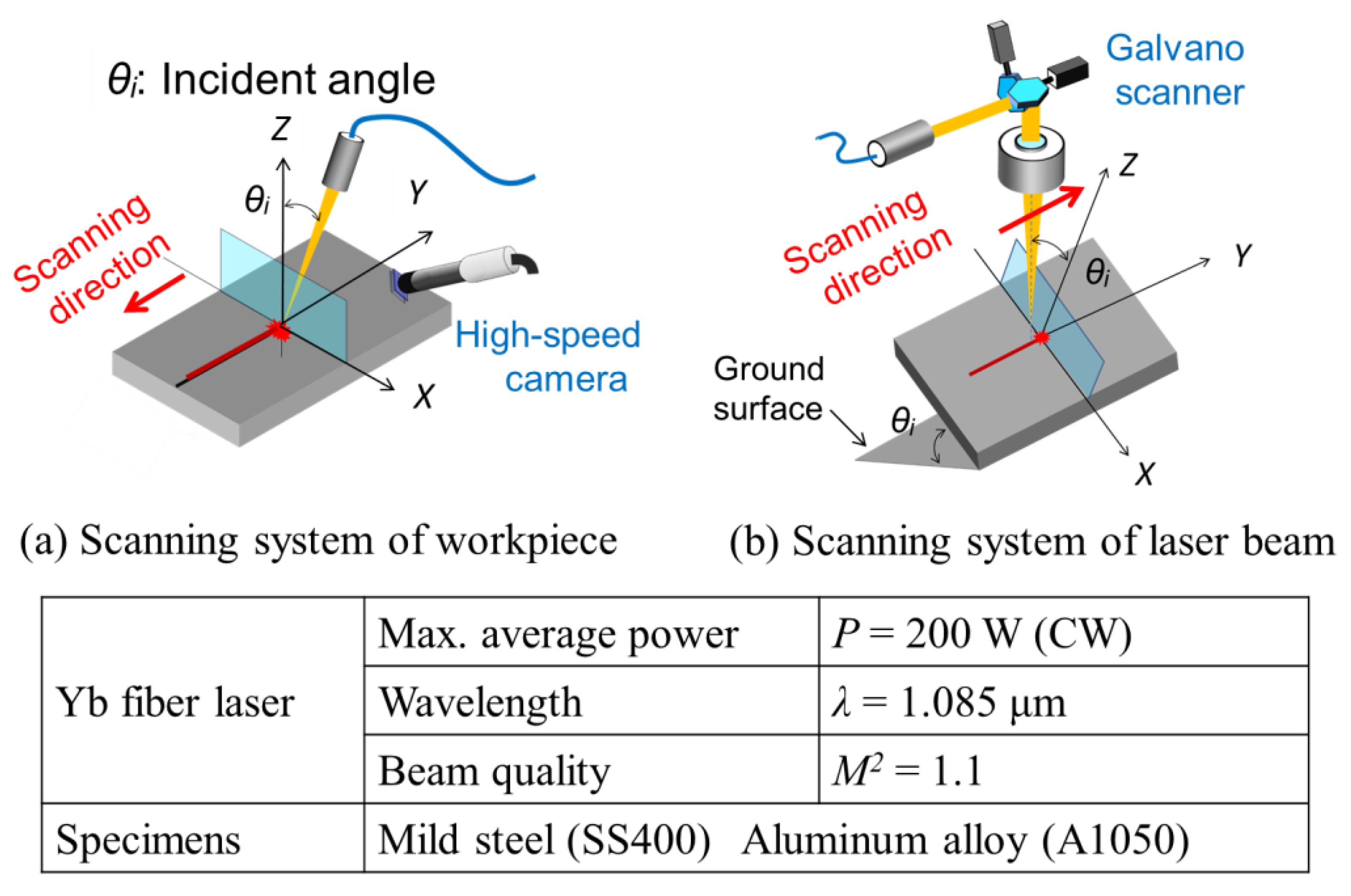
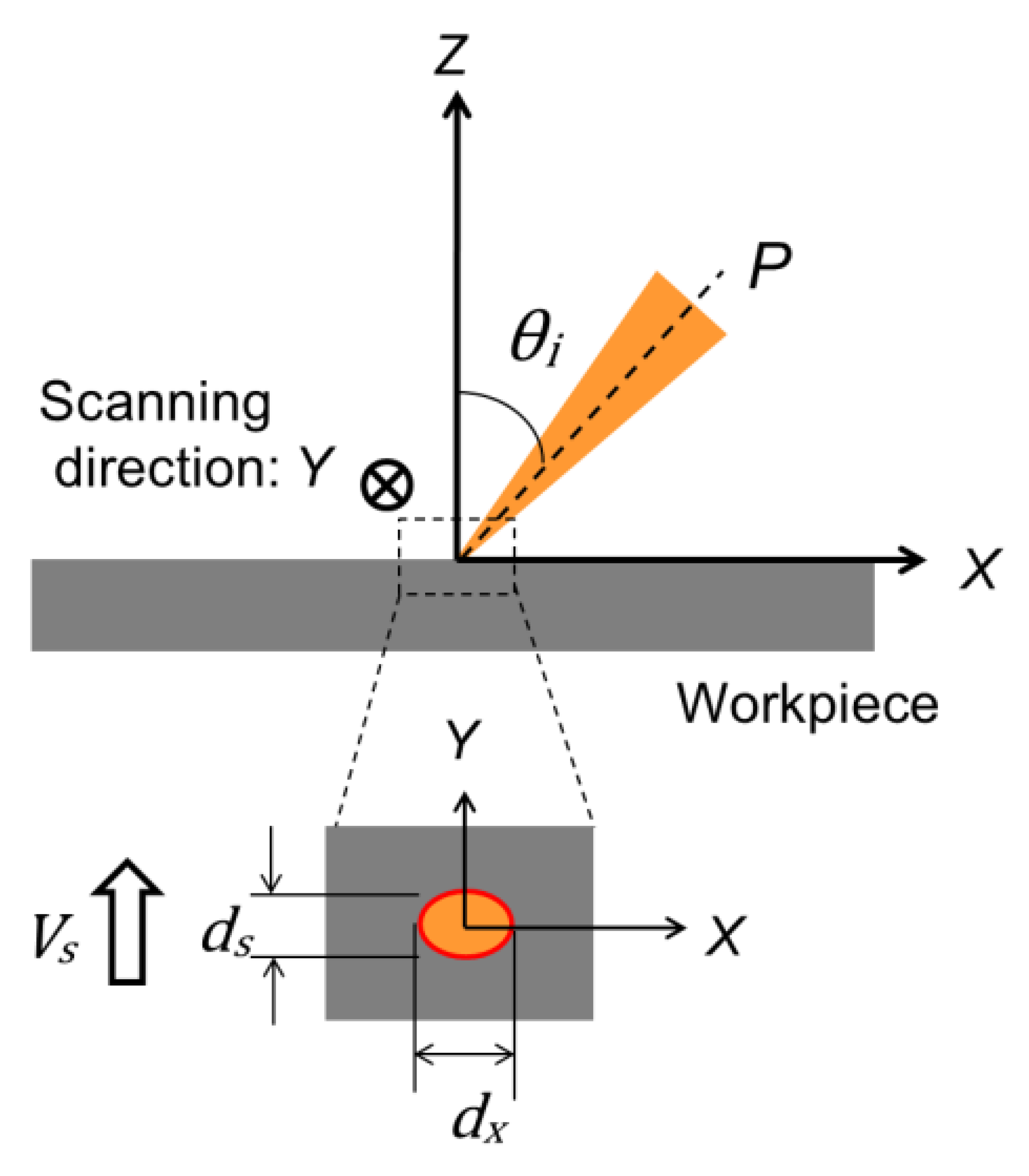
2. Experimental Setup

A single-mode CW fiber laser (IPG Photonics, Germany, YLR-200-SM) was used as the laser source. The maximum average power, P, and wavelength, λ, are 200 W and 1.085 μm, respectively. The M2 value representing beam quality was approximately 1.1. Polarization of the laser beam was random. The groove formation characteristics of the mild steel SS400 and aluminum alloy A1050 4 mm in thickness were examined.
The experiments were conducted using two different setups. For the experiments at scanning speeds of less than 2 m/s and high-speed observation of the processed area, the workpiece was moved using a mechanical linear slider, as shown in Figure 1a. The workpiece was mounted horizontally on the jig of the slider. The Z axis is perpendicular to the XY plane, which is the surface of the workpiece. The laser beam was angled from the Z axis in the XZ plane, as shown in Figure 1a. The incident angle θi is defined as the angle between the Z axis and the laser beam axis in the XZ plane. The laser beam was focused into a spot diameter of 18 µm by a fused silica lens with a focal length of 100 mm. The dynamic phenomena in the processed area were observed using a high-speed microscope camera (Keyence, Japan, model VW-9000). The maximum resolution of this camera is 640 × 480 pixels at the frame rate of 4000 fps. The processed area was illuminated by a white light source, and a bandpass filter with a center wavelength of 440 nm was used to eliminate the bright light noise from the keyhole and molten metal.
In the other experimental setup, the laser beam was moved using a galvano scanner (GSI LUMONICS, Japan, model XY2026, M3ST) and an lens. This setup was used for relatively high-speed processing (up to 6 m/s), as shown in Figure 1b. The workpiece was tilted (θi) with respect to the ground surface, and the laser beam was irradiated downward vertically with respect to that ground surface. The definition of incident angle, θi, is the same as that shown in Figure 1a. The focal length of the lens was 165 mm, and the spot diameter was 35 μm. The focus was placed on the surface of the workpiece, and the micro-grooves were formed by single scanning of the laser beam in all the experiments.
Figure 2 shows a schematic diagram of the laser-irradiated area. The incident and reflection sides in angled laser irradiation are defined as shown in the figure. The shape of the focused laser beam on the surface of the workpiece becomes an ellipse owing to the projection of the angled irradiation, as shown in the figure. The irradiated laser beam diameter on the X axis, dx, is elongated with increasing incident angle. The power absorption rate of the random polarized laser beam is the average value of the P and S polarization waves. Its value for steel at wavelengths of approximately 1 μm is constant at approximately 30% for incident angles of 0–60° [19]. Therefore, the power absorbed by the workpiece can be regarded as constant within this angular range, and the irradiated power density decreases with increasing incident angle. The power density, Pd, was calculated using Equation (1), where P is the laser power, and ds and dx are the diameters in the processing direction and along the X axis, respectively. The energy density, Ed, is defined by Equation (2) in terms of the transit time, Tt, which is the time it takes for the beam to pass through the diameter (ds) in the processing direction, as expressed in Equation (3).
Pd = P/(π/4·ds·dx)
Ed = Pd·Tt
Tt = ds/Vs

3. Experimental Results and Discussion

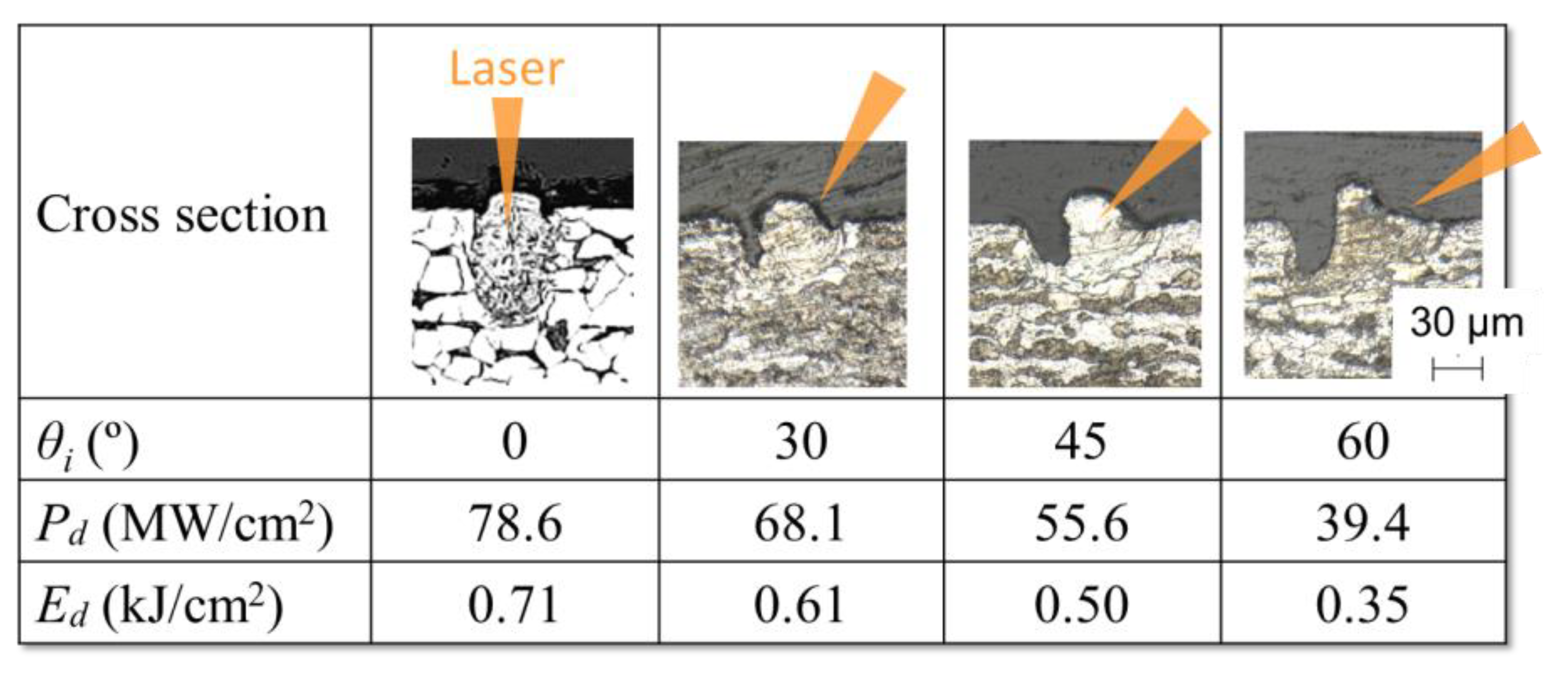
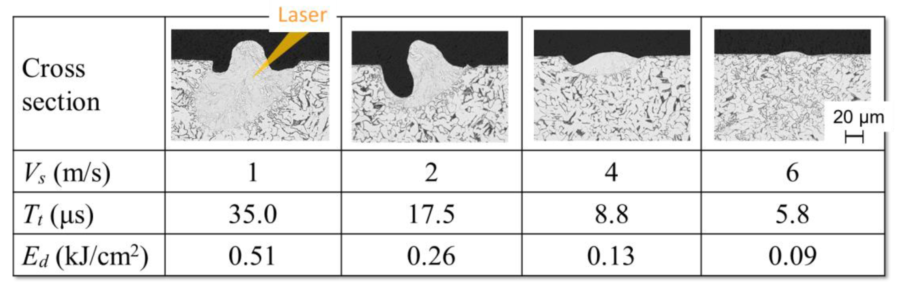
3.1. Effects of Incident Angle and Scanning Speed

The characteristics of the micro-grooves formed on the surface of mild steel (SS400) at various incident angles were examined. The mechanical slider setup was used for this experiment. Cross sections of the formed micro-grooves are shown in Figure 3, and the relationship between the incident angle, θi, and the groove depth, Dg, is shown in Figure 4. The incident angle, θi, was varied from 0 to 60°. The scanning speed, Vs, and irradiated laser power, P, were fixed at 2 m/s and 200 W, respectively.
As shown in Figure 3, deeper micro-grooves approximately 20 µm in depth were formed by angled irradiation, whereas no noteworthy grooves were formed by perpendicular irradiation (θi = 0°). The depth of the micro-grooves increased with increasing incident angle despite the decreasing power density. Note that a micro-groove was formed not on the incident side but on the reflection side by angled laser irradiation. The cross-sectional profile was different from that obtained by pulsed laser processing reported in a previous study [17].
The micro-groove shapes obtained at various scanning speeds were also examined using the beam scanning system. The scanning speed, Vs, was varied from 1 to 6 m/s. The cross sections of the micro-grooves are shown in Figure 4. The incident angle, θi, and laser power, P, were fixed at θi = 45° and P = 200 W, respectively. Therefore, the irradiated power densities, Pd, on the surface of the workpiece were constant at 14.7 MW/cm2 for all conditions. However, the energy density, Ed, decreased with increasing scanning speed, Vs, because of the decrease in the transit time, Tt, as shown in Equation (3) and Figure 2. The transit time, Tt, and energy density, Ed, are also listed in Figure 4. A maximum groove depth of 30 µm was obtained at a scanning speed of Vs = 2 m/s. The groove depth decreased at higher scanning speeds, as shown in Figure 4, because of insufficient energy density. Only shallow grooves were formed at a low scanning speed of Vs = 1 m/s. The behavior of the molten metal depends on the scanning speed, which affects formation of micro-grooves and upheaval. The groove formation mechanism will be discussed with the results of high-speed observation in the following sections.

3.2. High-Speed Observation of Processed Area

High-speed observation of the processed area was conducted in order to analyze molten metal flow and spatter. Figure 5a schematically illustrates the experimental setup to observe the surface of workpiece. The workpiece was moved by the mechanical slider, and the experimental conditions were fixed at the average power of P = 200 W, incident angle of θi = 45°, and scanning speed of Vs = 2 m/s. Figure 5b,c shows the captured images and its illustrations at the scanning speed of Vs = 1 and 2 m/s. The resolution of these captured images is 480 × 400 pixels. The frame rate and the exposure time of camera were 4000 fps and 2 µs, respectively. The keyhole and the molten metal flow could be recognized as the bright white areas in the images in Figure 5b,c. The white area on the incident side is clearer than that on the reflection side. The volume of molten metal is thought to be larger on the incident side. Note also that the molten metal on the incident side flows toward the center line of the scan path. By contrast, the molten metal flow on the reflection side is almost parallel to the scanning direction. At a point, Mp, a certain distance, L, behind the keyhole, the molten metal flow on the incident side reaches the center line of the scan path. The distance, L, increased with increasing scanning velocity of the laser beam, as shown in Figure 5b,c.
Next, to clarify the behavior of the spatter, the processed area on the XZ plane was observed under the same experimental conditions. Figure 6 shows the experimental setup and results. The frame rate, resolution, and exposure time of the captured image shown in Figure 6b are 23,000 fps, 210 × 160 pixels and 1.4 µs, respectively. The particles of molten metal clearly spread from the irradiated point and scattered toward the reflection side.

3.3. Micro-Groove Formation Mechanism

The mechanism of micro-groove formation is discussed by evaluating the formed micro-groove shapes and results of high-speed observation. Figure 7 schematically illustrates temperature distribution and scattering of spatter during angled laser irradiation.
Temperature distribution is symmetrical with respect to the laser beam axis for perpendicular irradiation of the surface of the workpiece. By contrast, temperature distribution is asymmetrical with respect to the laser beam axis for angled irradiation owing to the lack of geometrical balance. Therefore, a higher temperature region is formed on the surface of the reflection side because of the lower thermal conductivity of air, as shown in Figure 7a. In addition, the keyhole edge is close to the free surface exposed to the air, and many spatters are scattered toward the reflection side. On the incident side, the molten metal is thought to remain. Therefore, the molten metal distribution is asymmetric around the keyhole, and this is considered to be an important factor in groove formation by angled laser irradiation.
The behavior of the molten metal and the groove formation mechanism are illustrated in Figure 8 and Figure 9, respectively. Figure 8 shows a schematic diagram of the behavior of molten mild steel at a lower scanning speed. In this case, the metal is melted more deeply owing to the higher energy density, Ed, which results in a larger volume of molten metal, as shown in Figure 8a. The molten metal begins to flow into the groove formed on the reflection side after the laser beam has passed (Figure 8b). If the scanning speed of the laser beam is equal to or slower than the flow speed of the molten metal, the molten metal fills the groove before solidification. Consequently, no noteworthy groove is formed, as shown in the experimental result at Vs = 1 m/s in Figure 4. The small upheaval is considered to be the result of surface tension and contraction during solidification (Figure 8c).
The groove formation process at a higher scanning speed is schematically illustrated in Figure 9. The groove is formed on the reflection side, and the molten metal remains on the incident side, as in the case of a low scanning speed (Figure 9a). However, the pressure that forces the molten metal out of the keyhole is thought to be strong, especially ahead of the leading edge of the keyhole. The extruded molten metal from the keyhole has a large flow vector and changes direction because it is constrained by the surrounding solid metal. The flow vector opposite to the scanning direction and the strength can be maintained for a certain distance, L, behind the keyhole, and it is larger than the flow vector into the groove on the reflection side (Figure 9d). As a result, the molten metal is thought to be cooled and solidified while staying on the incident side, and the groove that is formed on the reflection side remains after processing is complete (Figure 9c).

3.4. Effects of Thermophysical Properties on Micro-Groove Formation

On the basis of the discussion in the previous section, the fluidity and cooling rate of the molten metal are thought to be particularly important factors for groove formation. To discuss the effects of these factors, micro-groove formation in aluminum alloy, which has different thermophysical properties from mild steel, was investigated.
Figure 10 compares the micro-grooves formed on the surfaces of mild steel (SS400) and aluminum alloy (A1050). The major thermophysical properties are listed in the figure. The laser power, scanning speed, and incident angle were P = 200 W, Vs = 2 m/s, and θi = 45°, respectively. The spot size, ds, was 35 µm for SS400 and 18 µm for A1050. Under these experimental conditions, only shallow grooves were formed in A1050, even during the same high-speed processing.
As in the low-speed processing of SS400, the formation of shallow grooves is attributed in part to the high fluidity of the molten aluminum resulting from its low viscosity. However, it is also necessary to consider the increase in molten volume due to the low melting point, low density, and low specific heat of aluminum and the increase in cooling rate due to its high thermal conductivity. Therefore, in micro-grooving by angled laser irradiation, it is necessary to optimize the laser irradiation conditions according to the thermophysical properties of the material. A numerical simulation of the molten metal behavior in a high-speed angled laser irradiation process is under development to qualitatively discuss the groove formation mechanism and to optimize the processing parameters.

4. Conclusions

High-speed micro-groove formation by angled irradiation was investigated using a single-mode CW fiber laser, and the formation mechanism of the micro-grooves was discussed using the results of high-speed camera observation. The main conclusions of this study are as follows.
(1)
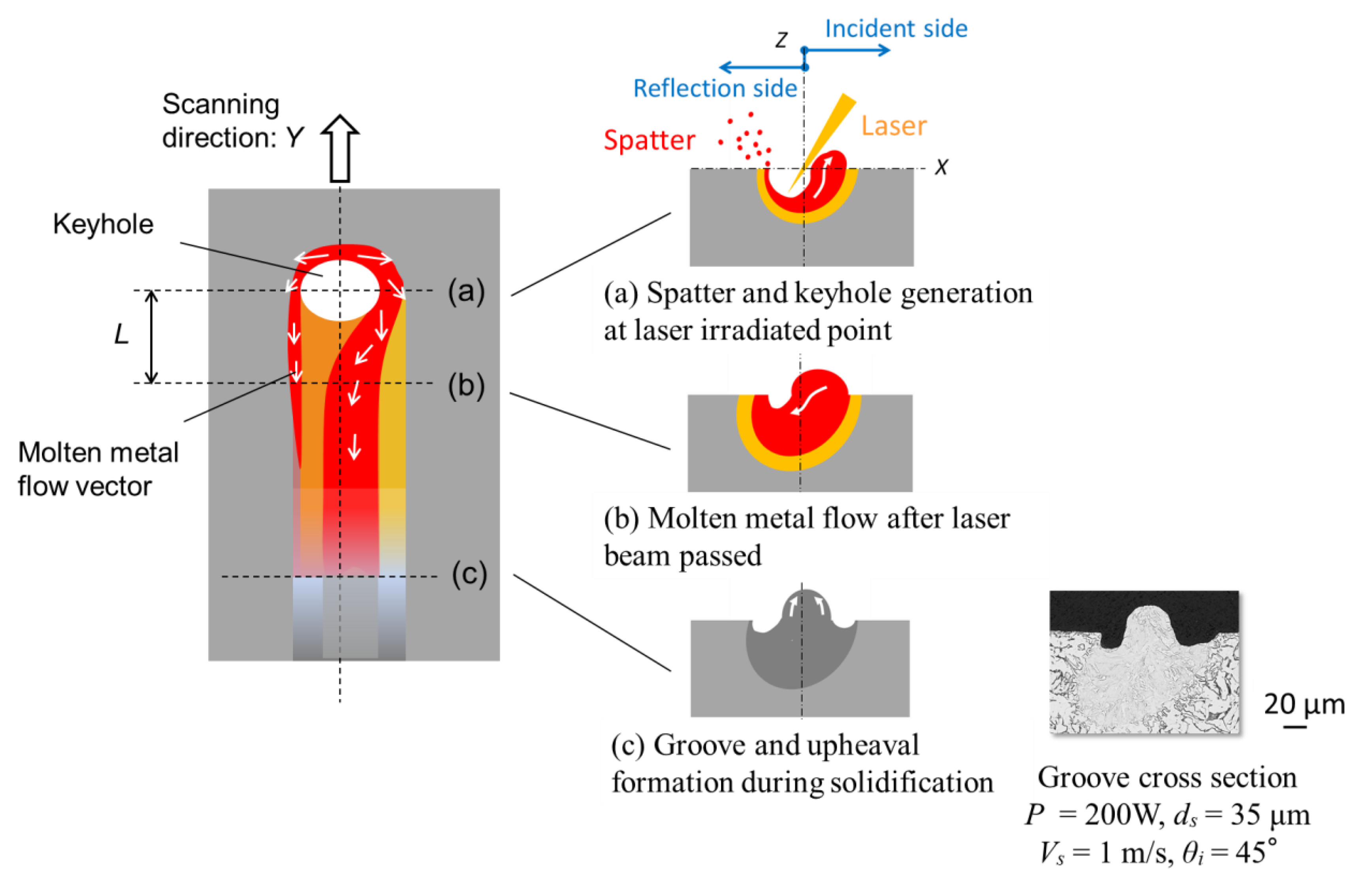
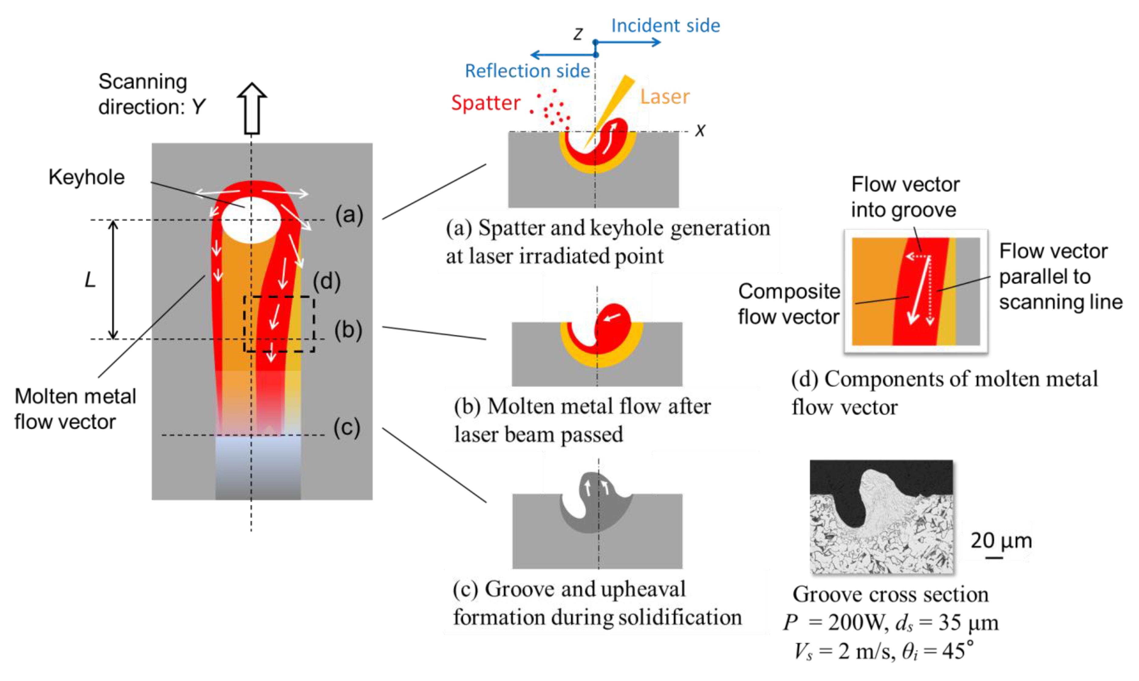
Use of angled laser irradiation combined with high-speed scanning of the laser beam can result in formation of a micro-groove on the reflection side of the laser irradiation.
(2)
A relatively deep groove more than 30 μm in depth was obtained on the surface of mild steel at a laser power of P = 200 W, a scanning velocity of Vs = 2 m/s, and an irradiation angle of θi = 45°, whereas no noteworthy groove was formed by perpendicular irradiation.
(3)
Many spatters on the reflection side and the flow of molten metal on the incident side were observed using a high-speed camera. The groove formed on the reflection side immediately after laser irradiation and the subsequent flow and solidification of the molten metal on the incident side are thought to be important factors for micro-groove formation.
(4)
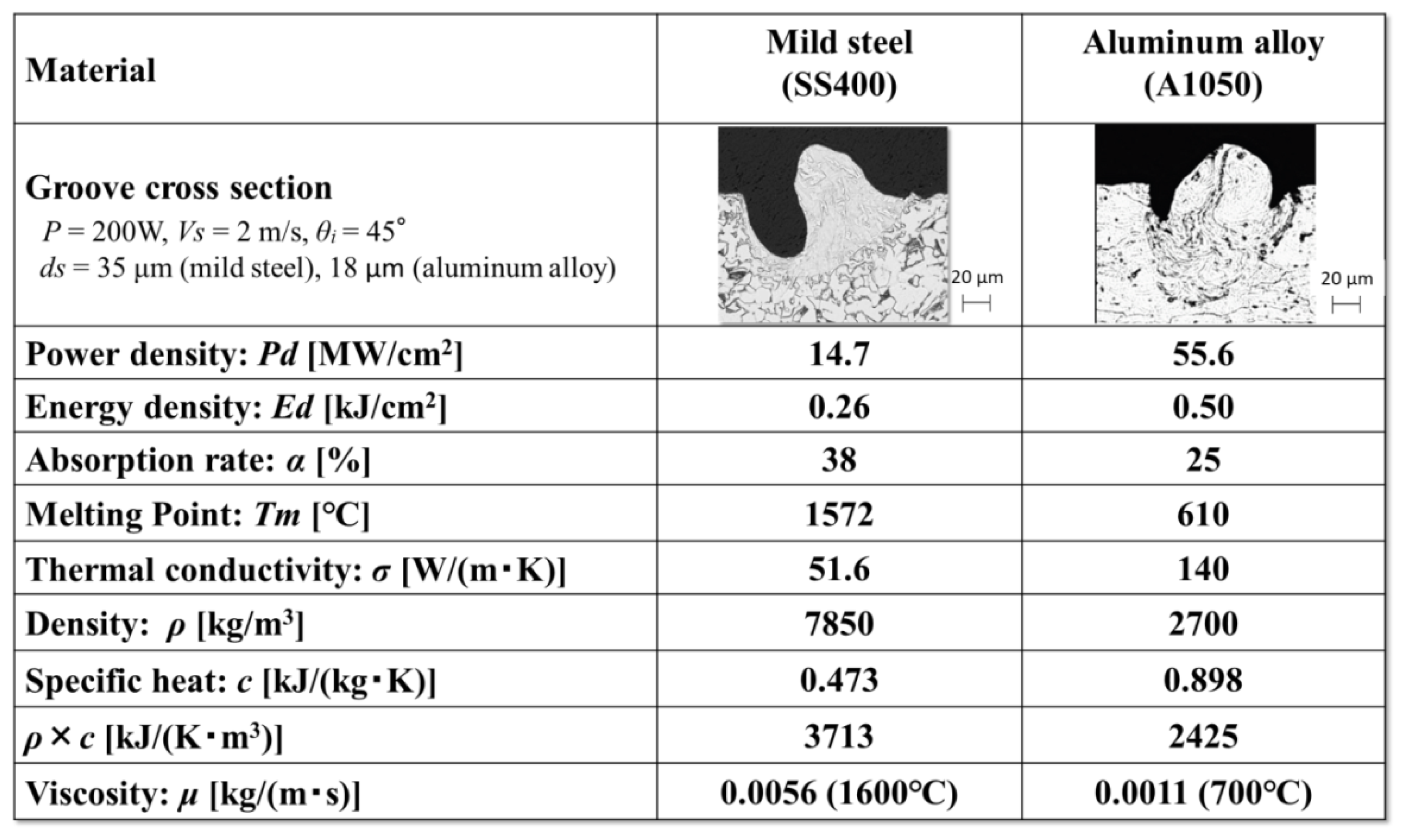
Only shallow grooves were formed on the surface of aluminum alloy, even during high-speed processing by angled laser irradiation. It is necessary to optimize the laser irradiation conditions according to the thermophysical properties of the material.

Author Contributions

Conceptualization, T.S., H.I., and Y.O.; Validation, T.S. and C.K.; Investigation, T.S., H.I. and C.K.; Writing-original draft preparation, T.S.; Writing-review and editing, Y.O.; Supervision, A.O. All authors have read and agreed to the published version of the manuscript.

Funding

This research received no external funding.

Conflicts of Interest

The authors declare no conflict of interest.

References

  1. Lopez, J.; Mincuzzi, G.; Devillard, R.; Zaouter, Y.; Hönninger, C.; Mottay, E.; Kling, R. Ablation efficiency of high average power ultrafast laser. J. Laser Appl. 2015, 27, S28008. [Google Scholar] [CrossRef]
  2. Loeschner, U.; Schille, J.; Streek, A.; Knebel, T.; Hartwig, L.; Hillmann, R.; Endisch, C. High-rate laser microprocessing using a polygon scanner system. J. Laser Appl. 2015, 27, S29303. [Google Scholar] [CrossRef]
  3. Aguilar-Morales, A.I.; Alamri, S.; Lasagni, A.F. Micro-fabrication of high aspect ratio periodic structures on stainless steel by picosecond direct laser interference patterning. J. Mater. Process. Technol. 2018, 252, 313–321. [Google Scholar] [CrossRef]
  4. Rodríguez-Vidal, E.; Sanz, C.; Lambarri, J.; Quintana, I. Experimental investigation into metal micro-patterning by laser on polymer-metal hybrid joining. Opt. Laser Technol. 2018, 104, 73–82. [Google Scholar] [CrossRef]
  5. Dunn, A.; Carstensen, J.V.; Wlodarczyk, K.L.; Hansen, E.B. Nanosecond laser texturing for high friction applications. Opt. Laser Eng. 2014, 62, 9–16. [Google Scholar] [CrossRef] [Green Version]
  6. Rodríguez-Vidal, E.; Matthews, D.T.A.; Sáenz de Viteri, V.; Korver, F.; Wentink, D.J. Surface design and texturing of strip steel using nanosecond pulsed lasers for simulated roughness transfer and paint appearance. J. Mater. Process. Technol. 2020, 275, 116365. [Google Scholar] [CrossRef]
  7. Farasi, A.Y.; Mwenifumbo, S.; Rahbar, N.; Chen, J.; Li, M.; Beye, A.C.; Arnold, C.B.; Soboyejo, W.O. Nano-second UV laser processed micro-grooves on Ti6Al4V for biomedical applications. Mater. Sci. Eng. C. 2009, 29, 5–13. [Google Scholar]
  8. Kawahito, Y.; Tange, A.; Kubota, S.; Katayama, S. Development of Direct Laser Joining for Metal and Plastic. In Proceedings of the 25th International Congress on Applications of Lasers & Electro-Optics (ICALEO), Scottsdale, AZ, USA, 30 October–2 November 2006. Paper #604. [Google Scholar] [CrossRef]
  9. Roesner, A.; Olowinsky, A.; Gillner, A. Innovative Approach of Joining Hybrid Components. In Proceedings of the 28th International Congress on Applications of Lasers & Electro-Optics (ICALEO), Orlando, FL, USA, 2–5 November 2009. Paper #132. [Google Scholar] [CrossRef]
  10. Amend, P.; Pfindel, S.; Schmidt, M. Thermal joining of thermoplastic metal hybrids by means of mono- and polychromatic radiation. Phys. Procedia 2013, 41, 98–105. [Google Scholar] [CrossRef] [Green Version]
  11. Huang, B.; Sun, L.; Li, L.; Zhang, L.; Lin, Y.; Che, J. Experimental investigation of the strength of polymer-steel direct adhesion (PSDA) joints with micro-structures ablated by laser. J. Mater. Process. Technol. 2017, 249, 407–414. [Google Scholar] [CrossRef]
  12. Freitag, C.; Wiedenmann, M.; Negel, J.; Loescher, A.; Onuseit, V.; Weber, R.; Ahmed, M.A.; Graf, T. Ultra-Short Pulse Laser Processing of CFRP with Kilowatt Average Power. In Proceedings of the 33rd International Congress on Applications of Lasers & Electro-Optics (ICALEO), San Diego, CA, USA, 19–23 October 2014. Paper #702. [Google Scholar] [CrossRef]
  13. Straeten, K.; Nottrodt, O.; Zuric, M.; Olowinsky, A.; Abels, P.; Gillner, A. Polygon scanning system for high-power, high-speed microstructuring. Procedia CIRP 2018, 74, 491–494. [Google Scholar] [CrossRef]
  14. Rodríguez-Vidal, E.; Sanz, C.; Etxarri, J.; Bejarano, A.; Lebour, Y.; Malet, R. Modification of ABS wetting properties by ultrashort and short pulse lasers. Procedia CIRP 2018, 74, 568–572. [Google Scholar] [CrossRef]
  15. Ismail, M.I.S.; Okamoto, Y.; Okada, A.; Uno, Y. Experimental investigation on micro-welding of thin stainless steel sheet by fiber laser. Am. J. Eng. Appl. Sci. 2011, 4, 306–312. [Google Scholar] [CrossRef] [Green Version]
  16. Wang, H.; Chen, X.; Zhang, W. Effects of laser beam lead angle on picosecond laser processing of silicon nitride ceramics. J. Laser Appl. 2019, 31, 042011. [Google Scholar] [CrossRef]
  17. Rodríguez-Vidal, E.; Sanz, C.; Soriano, C.; Leunda, J.; Verhaeghe, G. Effect of metal micro-structuring on the mechanical behavior ofpolymer–metal laser T-joints. J. Mater. Process. Technol. 2016, 229, 668–677. [Google Scholar] [CrossRef] [Green Version]
  18. Katayama, C.; Okamoto, Y.; Sakai, T.; Kadonaga, S.; Okada, A. Investigation of Micro-grooving of Metals by High-speed Scanning of CW Laser. In Proceedings of the 8th International Conference of Asian Society for Precision Engineering and Nanotechnology (ASPEN), Matsue, Japan, 12–15 November 2019. B04-1-2. [Google Scholar]
  19. Dausinger, F.; Shen, J. Energy coupling efficiency in laser surface treatment. ISIJ Int. 1993, 33, 925–933. [Google Scholar] [CrossRef] [Green Version]
Figure 1. Schematic diagrams of experimental setups.
Applsci 10 08333 g001
Figure 2. Schematic diagram of laser-irradiated area.
Applsci 10 08333 g002
Figure 3. Cross sections of micro-grooves obtained at various incident angles (Power (P) = 200 W, scanning speed (Vs) = 2 m/s, and diameter in the processing direction (ds) = 18 μm, mild steel).
Applsci 10 08333 g003
Figure 4. Cross sections of micro-grooves obtained at various scanning speeds (P = 200 W, incident angle (θi) = 45°, ds = 35 μm, and power density (Pd) = 14.7 MW/cm2, mild steel).
Applsci 10 08333 g004
Figure 5. High-speed observation of processed surface.
Applsci 10 08333 g005
Figure 6. High-speed observation of spatter.
Applsci 10 08333 g006
Figure 7. Schematic illustrations of temperature distribution and spatter during angled laser irradiation.
Applsci 10 08333 g007
Figure 8. Schematic illustrations of molten metal behavior during angled laser irradiation with low-speed scanning (mild steel).
Applsci 10 08333 g008
Figure 9. Schematic illustration of molten metal behavior under angled laser irradiation during high-speed scanning (mild steel).
Applsci 10 08333 g009
Figure 10. Comparison of micro-grooves and thermophysical properties of mild steel and aluminum alloy (P = 200 W, θi = 45°, and Vs = 2 m/s).
Applsci 10 08333 g010
Publisher’s Note: MDPI stays neutral with regard to jurisdictional claims in published maps and institutional affiliations.

