Article

Numerical Analysis of EOD Helmet under Blast Load Events Using Human Head Model

by
Borja Valverde-Marcos
1,
Ignacio Rubio
1,
Jacobo Antona-Makoshi
2,
Anoop Chawla
3,
José Antonio Loya
4 and
Marcos Rodríguez-Millán
1,*
1
Department of Mechanical Engineering, University Carlos III of Madrid, Avda. de la Universidad 30, Leganés, 28911 Madrid, Spain
2
Japan Automobile Research Institute, 2530 Karima, Tsukuba, Ibaraki 305-0822, Japan
3
Department of Mechanical Engineering, Indian Institute of Technology, New Delhi 110016, India
4
Department of Continuum Mechanics and Structural Analysis, University Carlos III of Madrid, Avda. de la Universidad 30, Leganés, 28911 Madrid, Spain
*
Author to whom correspondence should be addressed.
Appl. Sci. 2020, 10(22), 8227; https://doi.org/10.3390/app10228227
Submission received: 30 October 2020 / Revised: 13 November 2020 / Accepted: 17 November 2020 / Published: 20 November 2020
(This article belongs to the Special Issue Armour and Protection Systems)

Abstract

:
Brain injury resulting from improved explosives devices (IEDs) is identified as a challenge for force securities to improve protection equipment. This paper focuses on the mechanical response of explosive ordnance disposal (EOD) helmet under different blast loadings. Limited published studies on this type of helmet are available in the scientific literature. The results obtained show the blast performance of the EOD helmet because a decrease in the maximum values in the measured damage parameters is found. Therefore, an EOD helmet minimizes the risks of the severity of injuries on the user showing a low probability of injury.

1. Introduction

Nowadays, due to armed conflicts and terrorist threats, people injured and killed by explosive devices as weapons represent a significant percentage worldwide. Improvised explosive devices (IEDs) are the leading cause of death among Western troops on missions in conflict zones. IEDs have caused, for example, some 312,000 mild traumatic brain injuries (mTBI) among the US military between 2000 and 2018 [1].
The use of explosive weapons in conflict scenarios has to lead to the need of protecting troops from blast explosions, particularly the bomb squad, whose specialty is handling explosives. First personal protection equipment appeared in the First World War and has evolved to the modern suits worn by the explosive deactivation technicians or EOD (explosive ordnance disposal) suits.
The analysis of combat helmets, usually ACH (Advanced Combat Helmet) or similar, has been done for ballistic threats using international standards such as STANAG 2920 [2] or NIJ 0106 [3]. These studies vary from the analysis of the mechanical behavior of the helmet to the analysis of brain injuries.
Regarding the analysis of combat helmets subjected to blast waves, very few studies are found, and these are mostly performed on the same ACH combat helmet. The first few relevant studies on the analysis of blast-induced traumatic brain injury (bTBI) in users of military combat helmets were published around 2010 [4,5,6,7,8].
Zhang et al. [9] analyzed the attenuation capacity of an explosive wave in an ACH helmet. They have developed a finite element model in the LS-Dyna® software to evaluate the actions on the head, with and without the combat helmet. They have used four levels of overpressure of Bowen’s lung damage threshold curves, between 0.27 and 0.66 MPa; also analyzing the influence of head orientation. The modeled head has been previously validated with Intracranial Pressure (ICP) measurements on corpses in shock tube experiments. They concluded that the presence of the ACH helmet attenuates the explosive wave in comparison to the unprotected case/situation: the stress in the head and on the cranial cavity and the general ICP levels (Intracranial Pressure) are reduced. Moreover, a fraction of the impact energy is absorbed by the compression of the helmet-pads; meanwhile, a part is transmitted directly to the head but to a lesser extent than without a helmet.
Rodriguez Millan et al. [10] used a Finite Element Method (FEM) model in the ABAQUS software to analyze the effect of a fully covered ACH helmet, that is, a visor and a jaw guard have been added as complements to improve its effectiveness. They concluded that the presence of additional protective equipment reduces maximum pressures in the brain (ICP) by up to 5 times, and this guarantees that no skull fracture occurs. The underwash effect of military helmets as a mechanism for blast-induced traumatic brain injury has also been studied by different authors [11,12,13,14].
Tan et al. [15] have developed a virtual model of finite elements of a human head and a helmet in order to help in the design of the next generations of helmets for ballistic and explosion protection. They carried out simulations of the head (with and without the helmet) under explosion using a Eurelian–Lagrangian approach and using the CoBi-FEM code to simulate the problem. The model has been validated with experimental tests in shock tubes and focuses on defining possible transmission paths of the energy of the blast wave.
Tse et al. [16] analyzed numerically the performance of face shields of a polycarbonate–aerogel composite with ACH helmet subjected to different blast loadings. The use of aerogel showed better protection capability than the classical polycarbonate face shields. Recently, Li et al. (2020) carried out an experimental and numerical study to obtain the overpressure on the head in different blast wave directions. They used an ACH helmet without complements to protect the face. The main findings were that the front direction was the more injurious direction, and the pads played a significant role to protect by reducing the overpressure; however, it can increase the impulse inside the helmet.
Our paper focuses on the blast protective helmet used in the explosive ordinance disposal (EOD) suit. This type of blast protective helmet has been hardly analyzed in any scientific literature [17,18]. Bass et al. [17] developed an experimental methodology to evaluate the performance of the EOD helmet against explosive blasts. The assessment of the risk of head and thorax failure was carried out using a Hybrid III dummy. Dionee et al. [18] also developed an experimental study for the assessment against explosive charges using a Hybrid III simulant. The authors acknowledge that the applicable standards for blast protection (NIJ 0117.01 standard) can be improved and that the Hybrid III does not faithfully represent the human head behavior under this type of loads.
The current work includes the following contributions to the study of helmets for explosive threats: (i) A numerical study of explosions has been carried out on an approved complete assembly helmet currently operational in the Spanish police. (ii) A widely validated model of the human head–neck assembly has been used and adapted for use in simulations with explosives. (iii) The analysis of the influence of an EOD helmet on explosive threats has been introduced with injury criteria such as the center of gravity accelerations of the brain, the Gadd Severity Index (GSI), the Head Injury Criteria (HIC), or the pressure in the CSF, in addition to the commonly used ones (ICP, main deformations). (iv) A limit for the use of the helmet has been defined based on the widely accepted criterion of HIC and has been directly related to the severity of injuries produced.

2. Numerical Model

The finite element numerical model developed in this study consisted of an EOD helmet on a complete human head model, whereby it is possible to analyze the head response and defensive performance under explosive loads.
For this work, LS-Dyna finite element software is used. In this section, the different parts that compound the numerical model are described, as mechanical properties of each one, mesh description, and boundary conditions. It is worth mentioning that the human head model used in this work has been previously validated in other works [19,20].

2.1. Helmet Assembly Model

The EOD helmet used in this work is shown in Figure 1 and is divided into five parts: helmet shell, visor, insolating joint, and interior foams, as known as hard foam and soft foam.
The parts are modeled using 3D solids through Autodesk Inventor CAD software from original dimensions of components and meshed with Altair Hypermesh software, which allows optimal mesh strategies for the helmet geometry. Some characteristics of the element type, size, and number used for the different parts are in Figure 1 and Table 1.
The helmet shell is the most external part and constitutes the principal structural element of the EOD helmet. It is made of composite based on aramid fiber, which is widely used in the field of personal protection [21,22,28,29,30,31,32] due to the excellent resistance to weight ratio. Helmet shell thickness is 4 mm. *MAT_COMPOSITE_DAMAGE (MAT_022) has been used to define the mechanical behavior model of aramid composite, where it is defined as orthotropic material (9 elastic constants) and assumes a linear elastic behavior until failure [31].
The damage criterion used in this part of the model is based on the Chang-Chang model [33,34] and considers three failure modes on composite: fiber breakage, matrix cracking, and matrix compression Equations (2)–(5). The direction assignment for the composite material is done in the local coordinate system (1,2,3), where 1 and 2 are the directions on the lamina plane, and 3 is the through thickness direction. It is worth mentioning that element deletion used is based on fiber tensile break.
The failure modes (MAT_022) used in this work can be described as follow:
At first, it is necessary to define τ ¯ parameter, the ratio between shear stress and shear strength as
τ ¯ = σ 12 2 2 G 12 + 3 α 1 σ 12 4 4 S c 2 2 G 12 + 3 α 1 S c 4 4
where G 12 is shear modulus, S c is the longitudinal shear strength, σ 12 is the shear stress, and α 1 is a non-linear shear stress coefficient (0 < α < 0.5) determined by stress measurements, for which, in this work, due to the lack of literature data about it, zero value is assumed.
-
Fiber breakage criterion is defined as
F f i b e r 2 = ( σ 11 X T ) 2 + τ ¯    ;   σ 11 > 0
where X T is the tensile strength in fiber direction (longitudinal) and σ 11 is the normal stress in that direction. When the failure criterion of Equation (2) is satisfied, F f i b e r 1 , all elastic constants involved on the failed lamina plane are set to zero, ( E 11 = E 22 = G 12 = v 12 = v 21 = 0 ). Failed fiber cannot support loads along the axial (or longitudinal) and shear (transverse) directions and load is redistributed to the rest of the lamina.
-
Matrix cracking criterion is defined as
F m a t r i x c r a c k 2 = ( σ 22 Y T ) 2 + τ ¯    ;   σ 22 > 0
where Y T is the tensile strength in the transverse direction (22-dir),
-
Matrix compression failure criterion is defined as
F m a t r i x   c o m p 2 = ( σ 22 2 s c ) 2 + [ ( Y c 2 s c ) 2 1 ] σ 22 Y c + τ ¯    ;   σ 22 < 0
Being Y c is the transverse compressive strength and σ 22 is the normal stress in that direction. When matrix cracking or matrix compression failure criterion is reached ( F m a t r i x c r a c k   o r   F m a t r i x c o m p   1 ), all of the elastic constants except E 11 , are set to zero, as the lamina cannot provide support in the shear directions of the fibers; hence, the corresponding shear modulus is also set to zero.
On the other hand, since it is a multilayer composite material, a failure criterion must be implemented for the delamination of the layers, which is formulated as follows:
F d e l a m 2 = ( m a x ( 0 , σ 3 ) S 3 ) 2 + ( τ 23 S 23 ) 2 + ( τ 1 S 13 ) 2
where S3, S13, and S23 are the tensile and shear strength in the thickness direction and σ 3 , τ 13 , τ 23 are normal and shear stress in out-of-lamina-plane direction.
Mechanical properties of aramid composite used in this work are listed in Table 2 [21,22,23].
The aforementioned mechanical behavior model, as well as the mechanical properties presented, are widely used in works that analyze the dynamic behavior, generally ballistic, of this type of composite materials used in personal protection.
The next element that makes up the protection is the visor gasket; it serves as a union between the fiber shell and the visor and also functions as an insulating element. It is made of rubber, and its mechanical behavior model has been assumed to be linearly elastic and has been implemented in the model through the *MAT_ELASTIC function whose defined properties are as follows: p = 1060 kg/m3, the elastic modulus is 5 GPa, and the Poisson coefficient 0.4.
The visor is the element that allows the visibility of the operator during handling tasks. It is made of transparent polycarbonate with a thickness of 22 mm. The MAT_PLASTIC_KINEMATIC card, suitable for modeling materials with isotropic and kinematic hardening by plastic deformation, has been used to define the mechanical behavior model of this material. The mechanical properties necessary to define the behavior of the material are defined below: density is p = 1200 kg/m3, the elastic modulus is 1.5 GPa, a Poisson coefficient 0.37, yield stress 62 MPa, and shear modulus is 32 MPa [24].
Finally, there are the polyurethane foams. These foams are made up of two components, hard foam to absorb impact energy and softer foam whose function is to provide comfort to the wearer. Using the MAT_LOW_DENSITY_FOAM card for low-density elastomeric foams with high compressibility, the behavior of both foams has been modeled, defining their respective properties. The mechanical properties of both foams have been obtained from other works [9,26,27]. In addition, it is necessary to define the stress–strain curves of this type of elastomers obtained experimentally. Polyurethane foams have a high strain rate sensitivity, and yield stress also tends to vary with the same parameter. Among all the studies carried out on the behavior of this type of foam, the one carried out by Moss and King [35] included experimental tests on both types of foams up to 50 s−1 strain rate. However, when the foams are subjected to ballistic impact or blast, strain rates reached much higher. Due to the lack of experimental data in literature at these strain rates, it is necessary, as developed in Reference [27], to extrapolate these stress–strain curves from those obtained at a low strain rate. In this way, the stress–strain curves used in this work are obtained from the study of Li et al. [27], where it extrapolates from strain rate of 2 s−1 to 2500 s−1, and are shown in Figure 2.
Furthermore, it is necessary to define the density and the elastic modulus for both foams, being 58 kg/m3 and 8.4 MPa for soft foam, and 66 kg/m3 and 0.84 MPa for hard foam, respectively. It is essential to mention that this type of foams is manufactured forming a single part with a total thickness of 14 mm where each half (through thickness) corresponds to hard and soft foam. For this model, the foams have been modeled like a single homogeneous solid assigning soft and hard foam properties to each half of solid properties.
Concerning the mesh, helmet assembly has 133,149 hexahedral solid elements. Mesh details of the helmet model have been shown previously in Figure 1.

2.2. Head Assembly Model

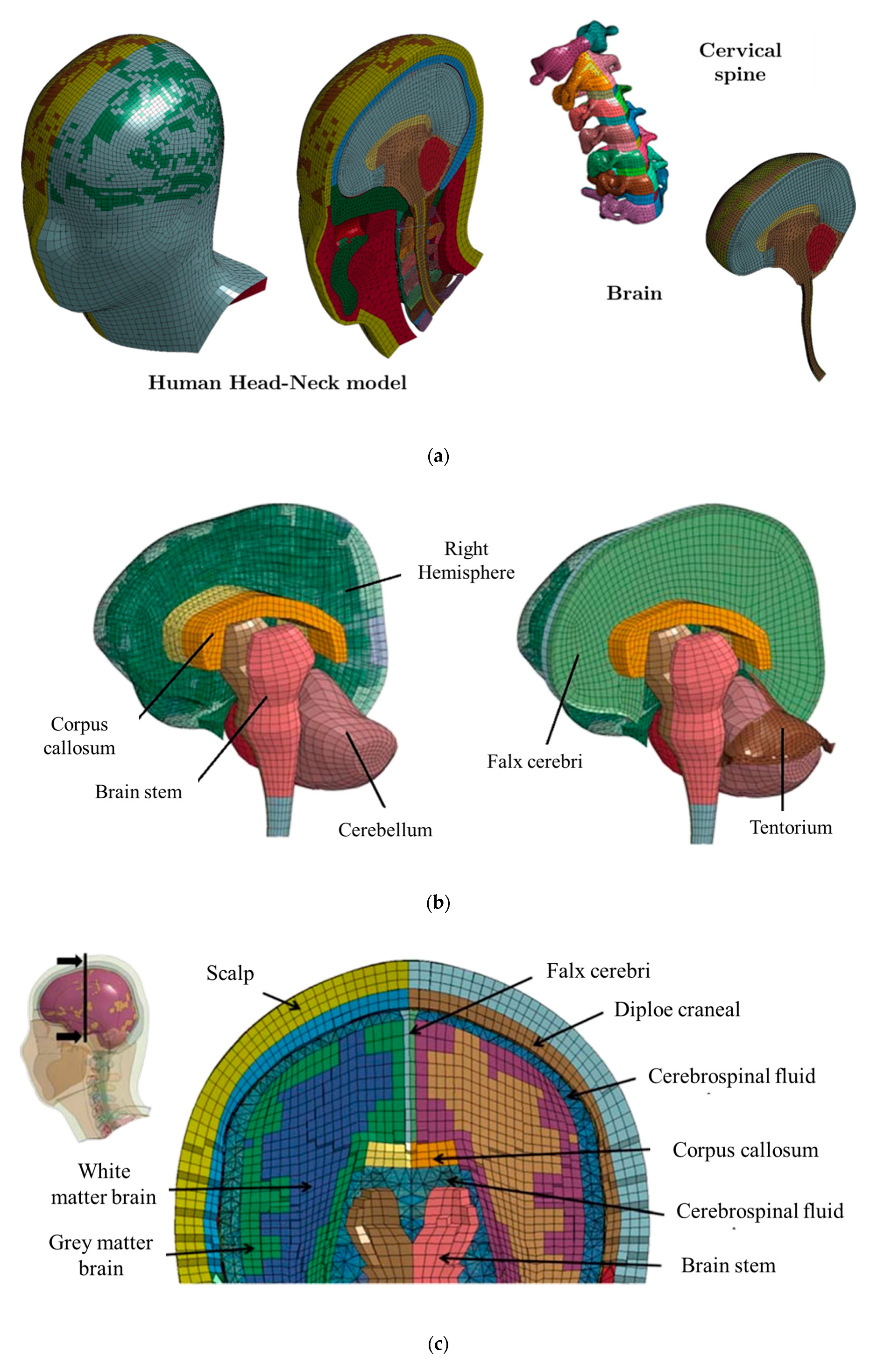
The human head finite element model used in this work has been developed by J. Antona-Makoshi [20]. This model was validated using different impact situations that own a high probability of occurring on traffic accident inducing cerebral injuries. The numerical head model shown in Figure 3 is based upon computed tomography (CT) and magnetic resonance imaging (MRI). It meshed using 291,948 solid elements and 53,609 shells elements.
The head is made up of multiple parts corresponding to a real human head: scalp, white and grey matter brain, corpus callosum, falx cerebri, etc. Moreover, the C1 to C7 vertebrae of the neck, with their corresponding intervertebral discs and ligaments, are included in the model. The total mass of the whole numerical model of the head with all its components is 6.47 kg. The head assembly model is shown in Figure 3.
The mechanical properties of the human head are obtained from the literature [20] and are listed below (Table 3).
The most relevant head constraints are contacts between vertebrae, modeled with *CONTACT_AUTOMATIC_SINGLE_SURFACE, contact between neck and vertebrae, modeled with *CONTACT_AUTOMATIC_SURFACE_TO_SURFACE, and the interaction between the dura and inner skull, modeled with *CONTACT_AUTOM_SURFACE_TO_SURFACE_TIEBREAK. The complete head model description is presented in the doctoral thesis of Dr. Antona-Makoshi [20].

2.3. Boundary Conditions and Contact Interactions

Boundary conditions applied to the model consist of the restrictions of all degrees of freedom of the nodes on the neck base. The head–helmet assembly was coupled due to the action of the helmet’s weight, warranting a good and snug fit.
The contact between the helmet assembly and head model was modeled using *CONTACT_AUTOMATIC_SURFACE_TO_SURFACE function with a friction coefficient of 0.2.
On the other hand, in a real-life situation, relative movement between head and helmet occurs, producing the expulsion of the helmet from the head. For this reason, it is necessary to use a fastening system for the helmet. It has been pointed out that under frontal charge, the influence of these retention systems on the performance of the helmet is insignificant in short-term events [10,22,42].

2.4. Blast Load Modelling

To simulate load blast, a hybrid technique that mixes the principal advantages of CONWEP (Conventional Weapons) and ALE (Arbitrary Lagrangian–Eulerian) method has been used through the implemented function in LS-Dyna, *LOAD_BLAS_ENHANCED. In this card, it is necessary to define coordinates where the explosion occurs, the time instant when it is produced, the type of the explosion (spherical or hemispherical expansion, reflected shock wave, etc.), and the amount of explosive load of trinitrotoluene (or the equivalent mass of TNT if a different explosive is used).
Table 4 shows a summary of the amount of explosive load and target distance used by various researchers.
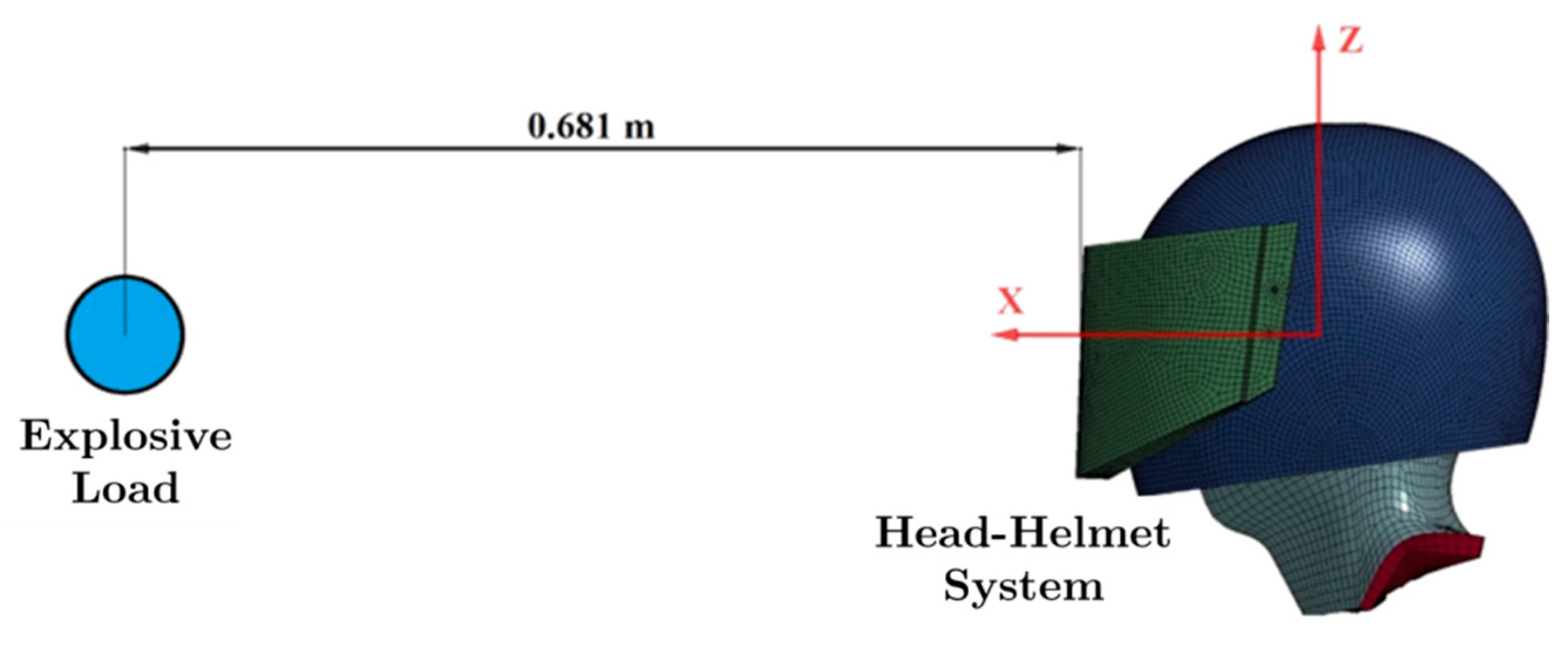
On the other side, NIJ0117 standard [49], concerning to test of protective equipment subjected to explosive loads, states that the experimental test must be carried out using a complete body Hybrid III Dummy, placed in a particular position (similar to deactivation-task position) and worn with complete protector equipment. The load is positioned at 0.77 m from the ground and 0.6 m from the target at 20 degrees under the horizontal from dummy eye-line [17]. However, this work focuses on the protective performance of the helmet only; the load is, therefore, placed at the same distance, but in the same horizontal plane, as is shown in Figure 4.
Furthermore, three different load cases have been analyzed: 0.050 kg, 0.075 kg, and 0.100 kg of TNT, for blast situations with/without a protective helmet, keeping the same load–target distance. The simulation time was 10 ms, similar to other studies [9,10,50] where it is considered sufficient to analyze the effects of the explosive.

2.5. Model Check and Validation

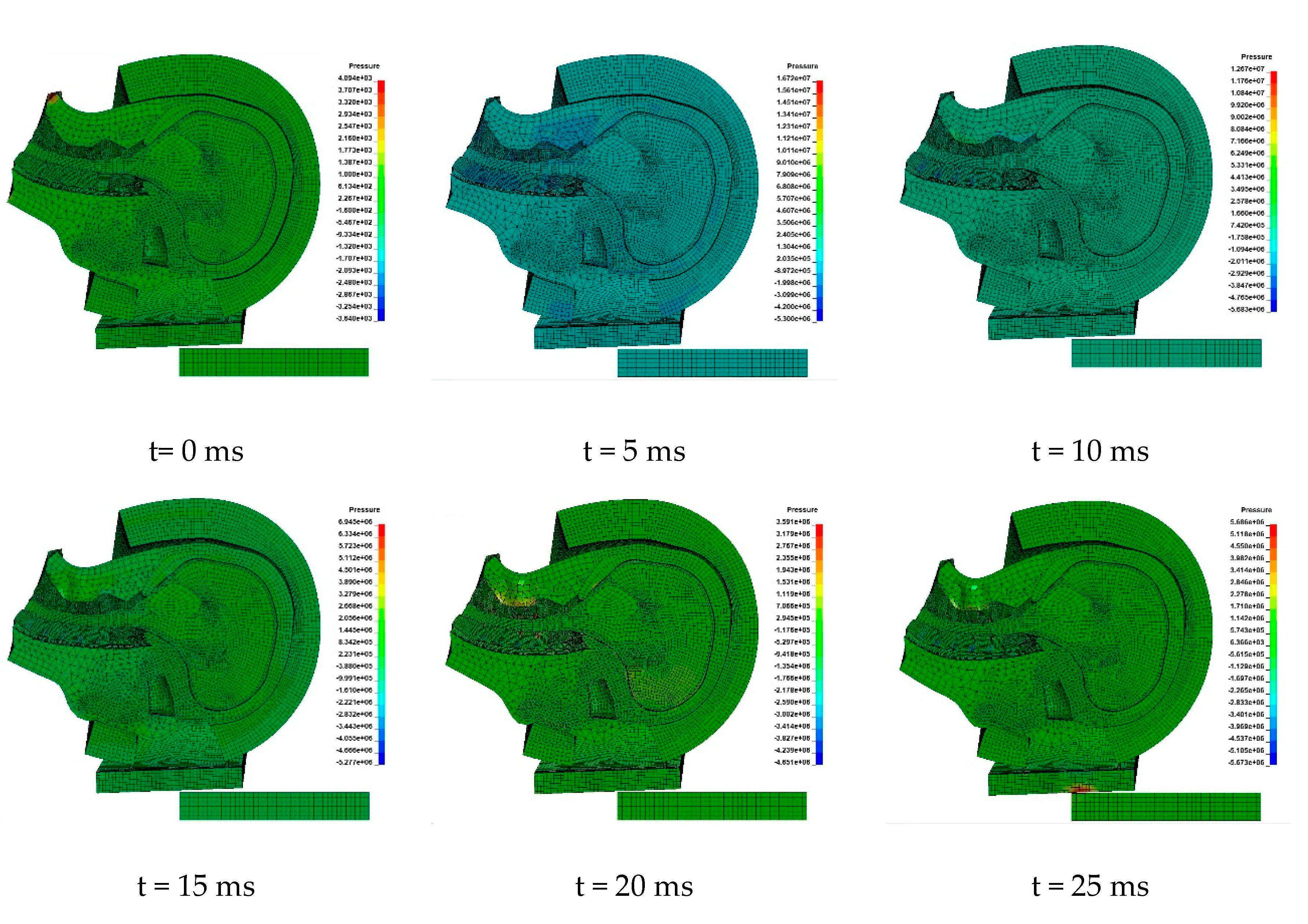
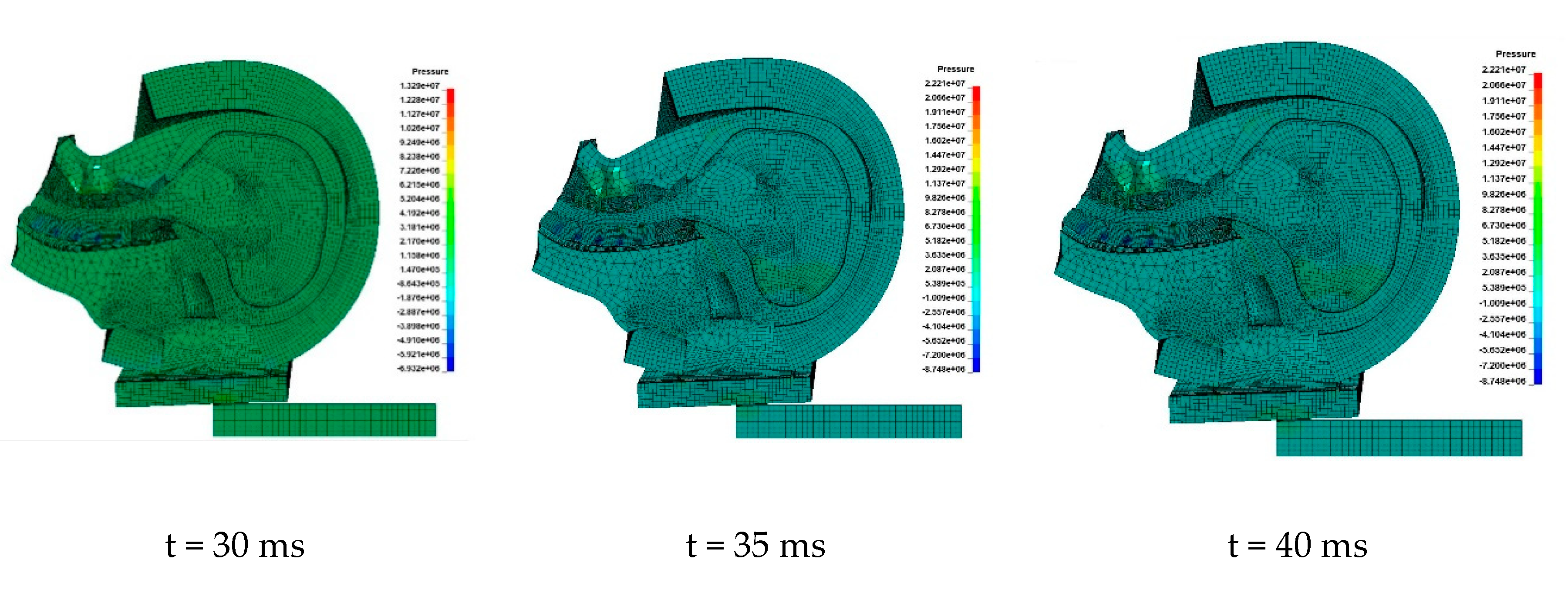
Due to the high logistical and economic complexity of carrying out explosive-type experimental tests, a drop test model of the head–helmet assembly has been performed numerically, where the contacts, the interactions between the different parts, are checked so that there is no penetration and the stress and strain fields are continuous.
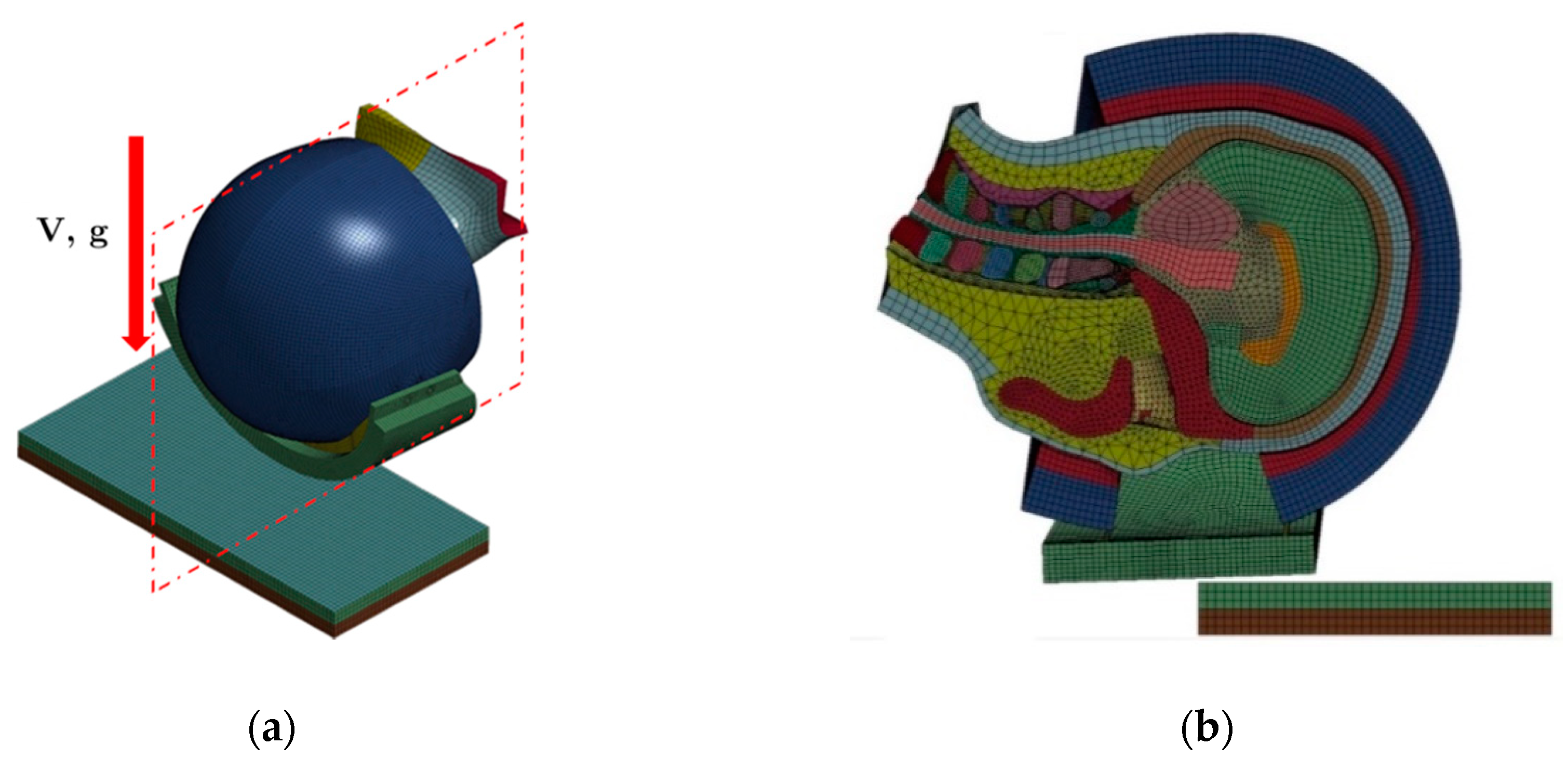
The model consists of a drop weight of the head–helmet assembly with an initial velocity of 1 m/s under gravity load so that a frontal impact is reproduced (Figure 5). The part where the assembly impacts consists of a flat plate with rigid properties (*MAT_RIGID) assigned and meshed with 20664 solid elements.
All nodes in the base of the neck have been restricted in all degrees of freedom except the displacement in drop direction. Moreover, the nodes of the plate were restricted entirely.
After drop weight simulation, good behavior of all elements involved in the model is observed, without penetrations between parts and without any element distortion that could produce numerical errors. This drop history is shown in Figure 6.

3. Results and Discussion

In this section, an analysis of results obtained in simulations has been carried out to assess the protective performance of the helmet under explosive load.
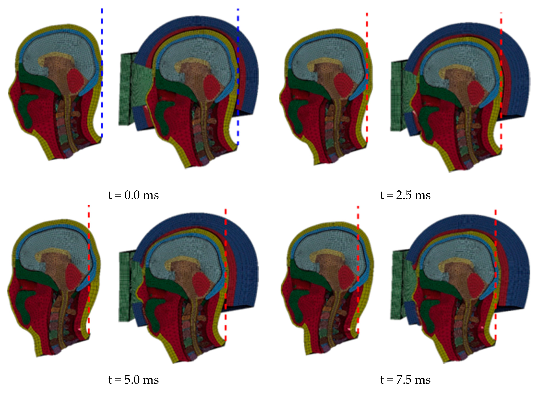
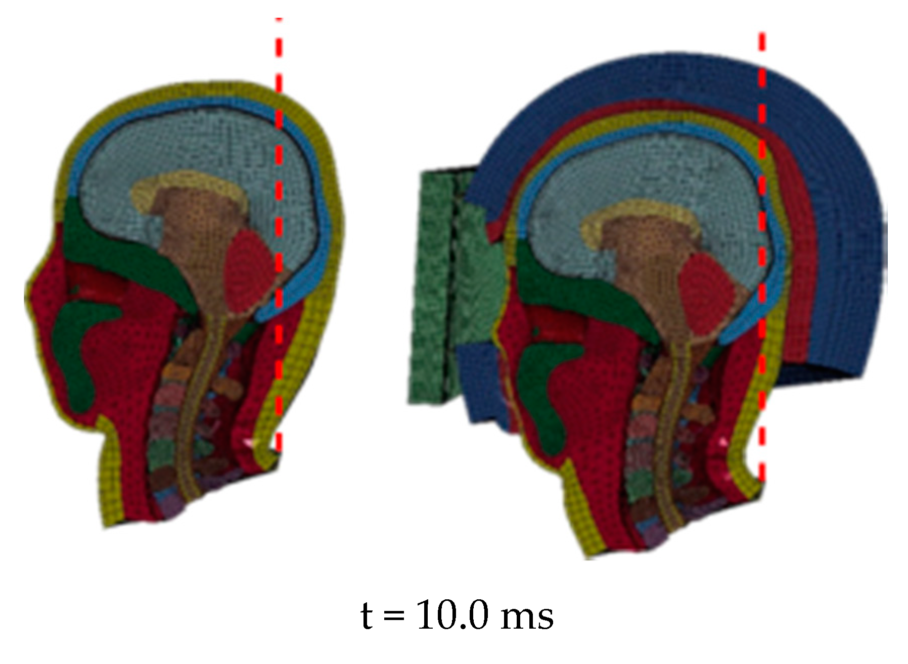
At first, Figure 7 shows the evolution of the simulation under the effect of the explosion of 0.100 kg TNT for both the cases, that is without and with the helmet.
In Figure 7, it is possible to observe that the use of helmet delays the wave impact with the head; besides, the inner foam absorbs part of the effect of this wave. The head acquires a higher backward neck extension movement for the cases when the helmet is not used. It has been observed that for longer than 10 ms analysis times, this movement is followed by a forward bending movement.
Next, to analyze the damage induced in the head of the wearer, different parameters are studied for brain damage analysis. These correspond to different injury criteria and include the acceleration of the center of gravity of the brain that allows calculating the GSI and HIC (Head Injury Criterion), the intracranial pressure, and the pressure of the spinal brain fluid, as well as the cerebellum strain.

3.1. Brain Acceleration

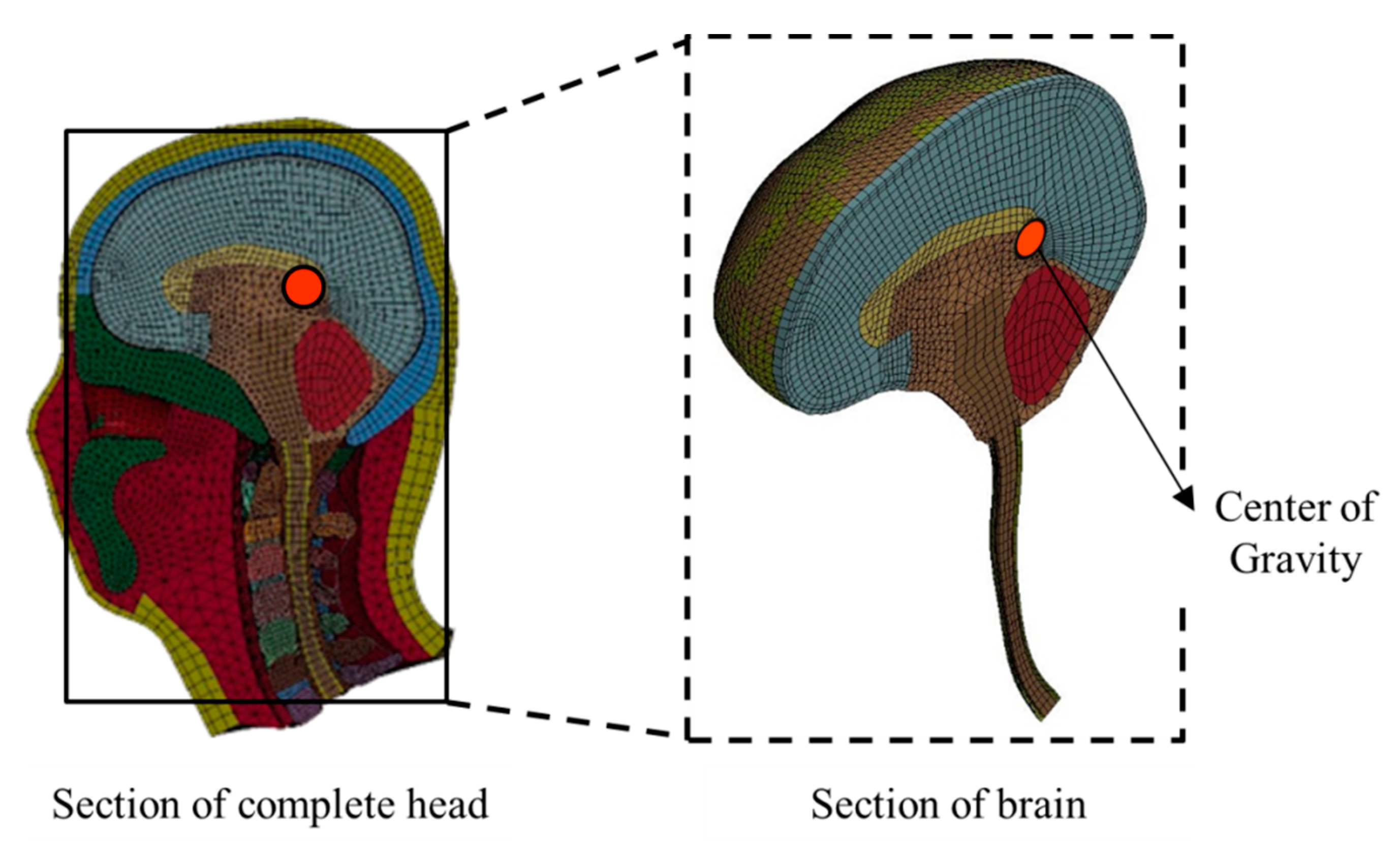
To obtain the brain CG acceleration, different parts of the head have been grouped: white and grey matter brain, corpus callosum, brain stem, cerebellum, falx cerebri, tentorium, and cerebrospinal fluid, as is shown in Figure 8.
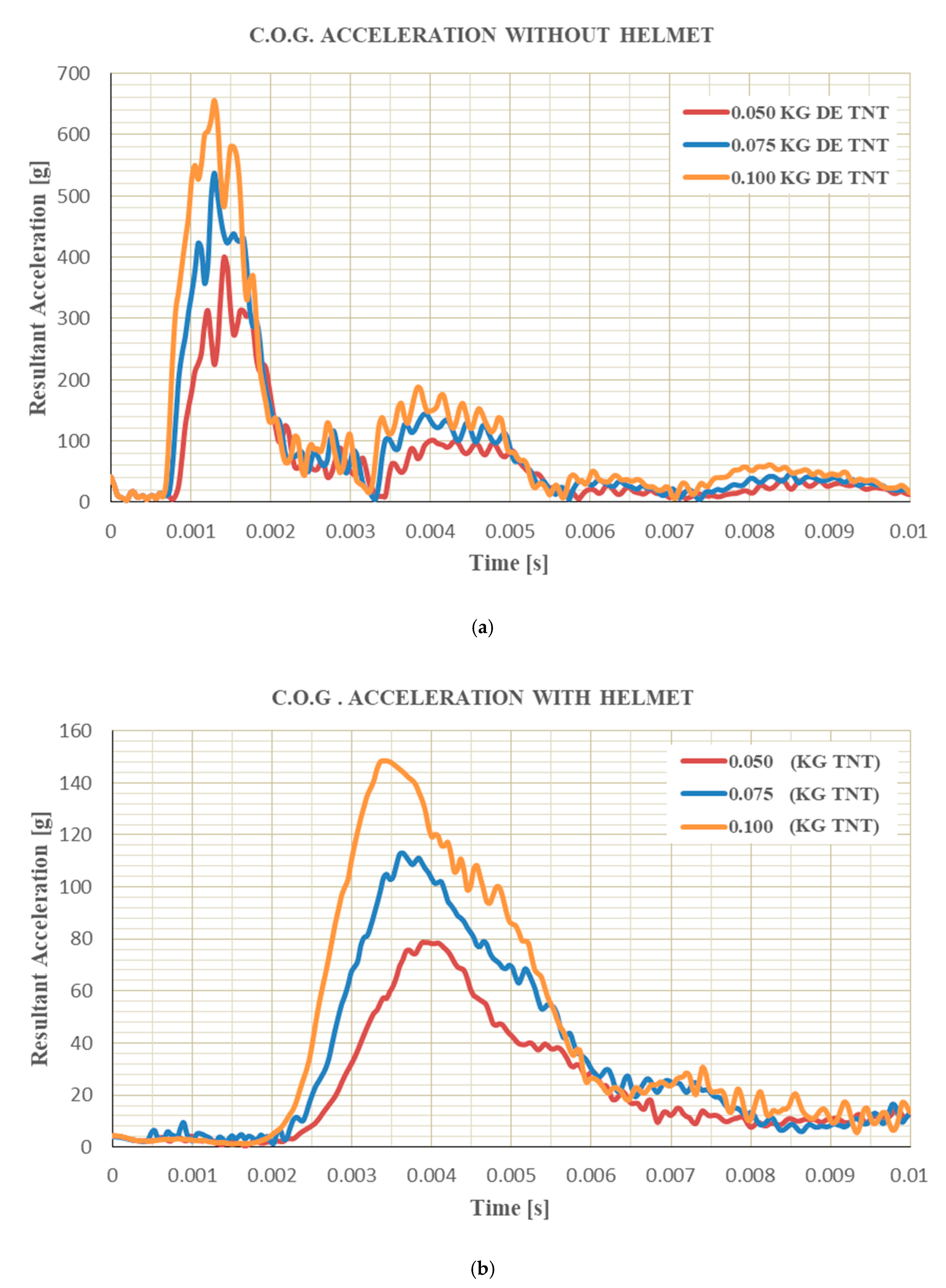
The obtained results of accelerations history, for both the cases (without and with helmet) and the three load masses, are presented in Figure 9.
Brain acceleration increase with the TNT mass for both the cases, reaching considerably higher values, in situations where the protective helmet is not used. Table 5 presents the maximum peak accelerations obtained from curves shown in Figure 9.
These values show a peak brain acceleration reduction of 80.29% for the case of lower TNT mass. In the intermediate case, the acceleration was reduced by 78.93%, and finally, for the 0.100 kg TNT explosion, the brain suffers 77.34% less when the helmet is used. Moreover, the time at which peak acceleration is reached increases significantly with the use of the helmet, attributed to the energy absorption by the helmet.
From these accelerations, it is possible to obtain relevant parameters to evaluate different brain injuries. These parameters are HIC (Head Injury Criteria) and GSI (Gadd Severity Index), whose analysis is shown below.

3.2. HIC and GSI Parameters

The head injury criterion is used to calculate the probability of brain injury due to trauma and bases its calculations on the acceleration of the center of gravity and the time interval that it acts. The expression of HIC is as follow:
H I C = { [ 1 t 2 t 1 t 1 t 2 a ( t ) d t ] 2.5 ( t 2 t 1 ) } m a x
On the other side, the GSI criterion is based on the acceleration–time curve and was proposed by Gadd [51] through the following expression
G S I = 0 t a ( t ) 2.5 d t
where “a” is the value of acceleration expressed in G’s, and ‘t’ is the time. According to this criterion, severe brain injuries occur (according to the AIS scale, presented later in Figure 10) if the GSI is greater than 1000. It is important to note that HIC and GSI, originally developed for blunt impact studies, are widely used in blast literature also, and have hence been used in this work.
Table 6 shows the HIC values obtained, and the GSI values for all the cases studied.
From the data presented in Table 6, it can be seen that the HIC value is reduced around 95% wearing helmet. In addition, GSI reduces by approximately 95% in all cases to values below the defined threshold value (1000). Therefore, in all the studied cases, according to the GSI criterion, there are no severe brain injuries when the protective helmet is used.
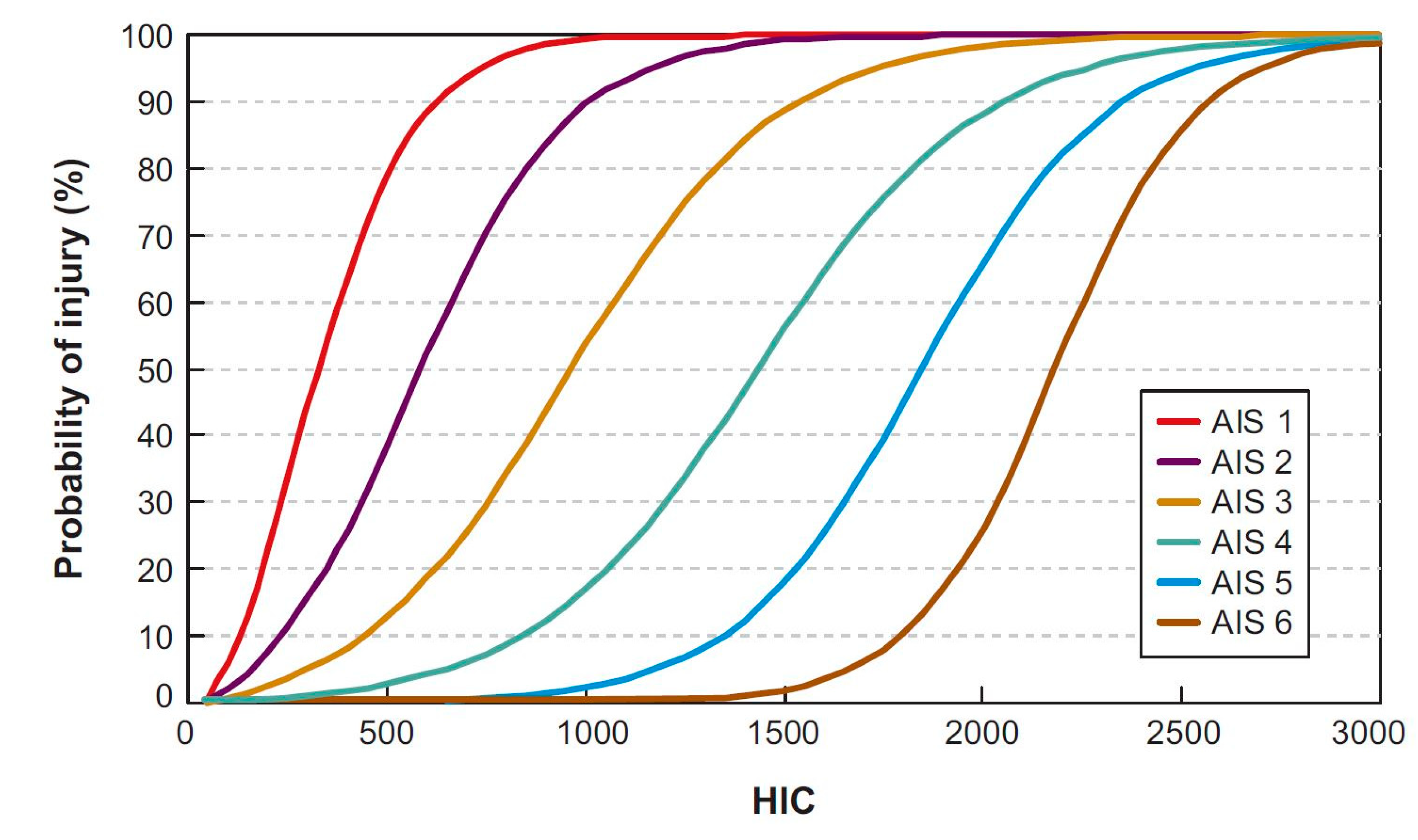
The HIC value can be related to the probability of brain injury at each level of the AIS scale, according to the risk curves presented by W.C. Hayes et al. [52] and shown in Figure 10.
Each AIS level of injury carries a severity level associated with it, with AIS1 being the mildest and AIS6 being the highest severity [53]. For example, the AIS1 level involves a mild concussion without loss of consciousness, while the AIS6 would imply severe damage to the brain with fatal injuries.
As presented in Table 7, on using the helmet, the probability of AIS ≥ 1 brain injuries reduced 98%, 84%, and 46% for 0.050, 0.075, and 0.100 kg of TNT, respectively. For 0.05 kg explosive, the possibility of AIS level 3 and 4 injuries is completely eliminated by the use of the helmet, while AIS 1 and 2 injuries have only a small probability of occurrence on use of the helmet.
On the other side, for intermediate cases (0.075 kg), the use of protective helmet plays an important role, as the probability of death (AIS 6 level injury), which is a near certainty without its use, gets eliminated with it. Helmet use also reduces that event to one with only a little probability of causing moderate injuries.
Finally, in the case with 0.100 kg TNT studied, the use of helmet again eliminates chances of a fatal injury and sets to close zero the possibility of AIS 3 and AIS4 level injuries. However, the possibility of AIS1 and AIS2 level injuries are not negligible and have a probability of 54% and 20%, respectively.
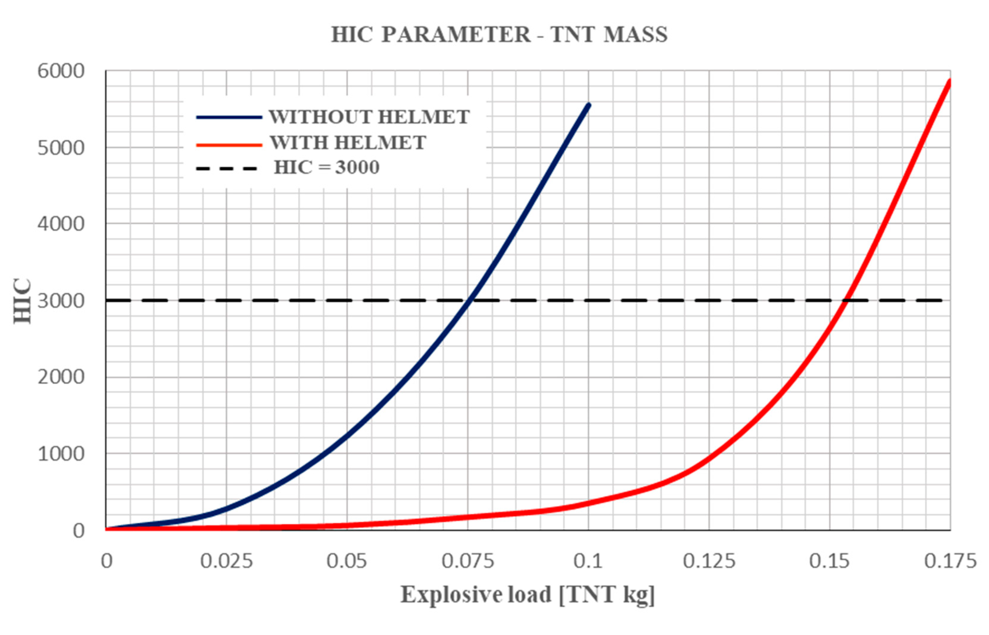
In addition, an analysis of the helmet applicability range was carried out. In order to determine the amount of TNT mass for which 3000 HIC value is reached (associated with a 100% probability of AIS 6 injury, implying severe brain damage leading to death), different explosive load states have been simulated. Figure 11 shows the curves obtained from this analysis.
In Figure 11, the exponential growth of HIC with TNT load was observed for both situations studied, with and without helmet. Here, for any arbitrary TNT load, the use of helmet reduces significantly the probability of injury.
Furthermore, the probability of death is close to 1 even if the protector helmet is used when the explosion is caused by a mass of close to 0.150 kg TNT (for the simulated conditions, that is at a distance 0.681 m). When an HIC value of 2693 is reached, it corresponds to a probability of 95% for the occurrence of AIS 6 injuries.
In the case of no helmet used, the critical load related to irreversible brain injuries is reduced almost half, around 0.075 kg. It should be noted that 0.050 kg would already be enough to cause significant injuries to the user; due to this, it has been decided not to study in this work the effect of loads greater than 0.100 kg.

3.3. Intracranial Pressure (ICP)

Another criterion used to analyze the injury risk is intracranial pressure proposed by Ward et al. [54] and is based on inner cranial pressure generated. In order to determine the potential injuries, based on maximum intracranial pressure, three ranges have been suggested [54]:
-
If peak pressure is higher than 235 kPa, severe brain injuries like a concussion are likely to be.
-
If peak pressure is in the range 173–235 kPa, the injuries produced are of a mild nature, such as hemorrhage in the cerebral cortex.
-
Finally, if peak pressure is lower than 173 kPa, there are no brain injuries or they are likely to be very slight.
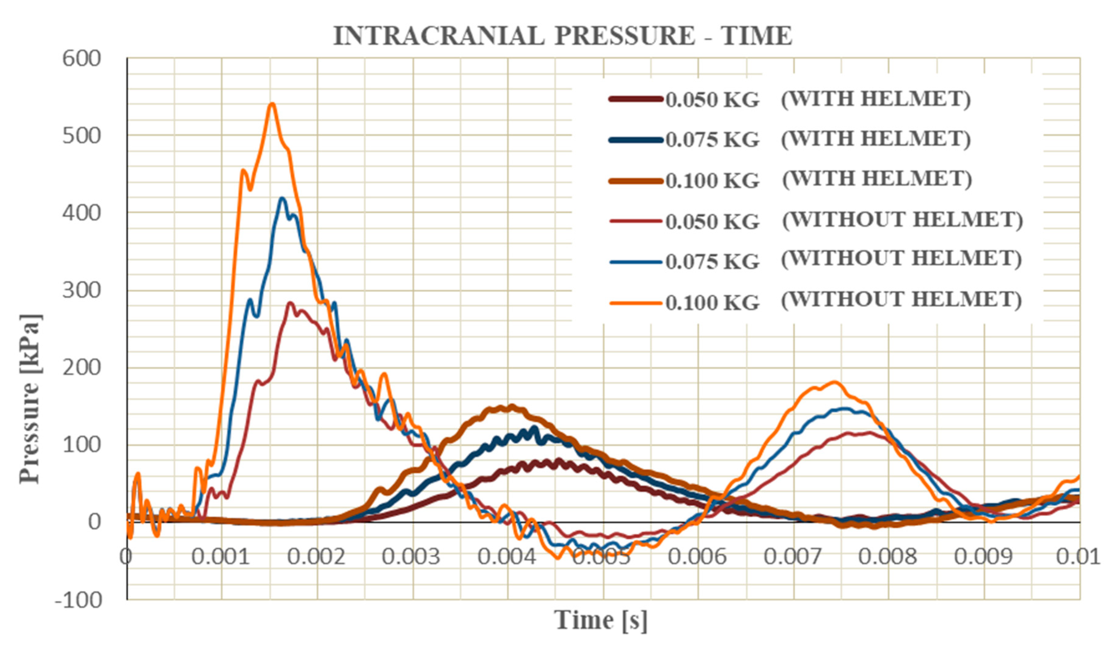
Figure 12 shows the ICP history for all studied cases of the brain area that receives the peak pressure is the external part of the frontal lobe, the place where the wave makes the first contact with the brain. The peak pressure is found somewhat higher on the forehead in the model with the EOD helmet.
Table 8 shows the peak pressure for each configuration studied. From obtained data, it is possible to affirm that the use of protective helmet reduces the intracranial pressure around 70% approximately in all the studied cases, decreasing the injuries of severe nature to very minor or no injuries presence.

3.4. Cerebrospinal Fluid Pressure

The analysis of the pressure in the cerebrospinal fluid due to the action of external loads allows us to know the degree of injury suffered. This criterion was formulated by Deck et al. [55] and related the cavitation in the cerebrospinal fluid with the probability of suffering a subdural hematoma. According to Reference [55], three pressure levels are differentiated, each related to the probability of suffering brain damage:
-
For pressures, lower than −94 kPa, there is a 5% probability of subdural hematoma.
-
For pressures between −94 kPa and −134 kPa, the probability increases to 50%.
-
And, finally, when pressure is between −134 kPa and −177 kPa, the probability of subdural hematoma increases to 95%.
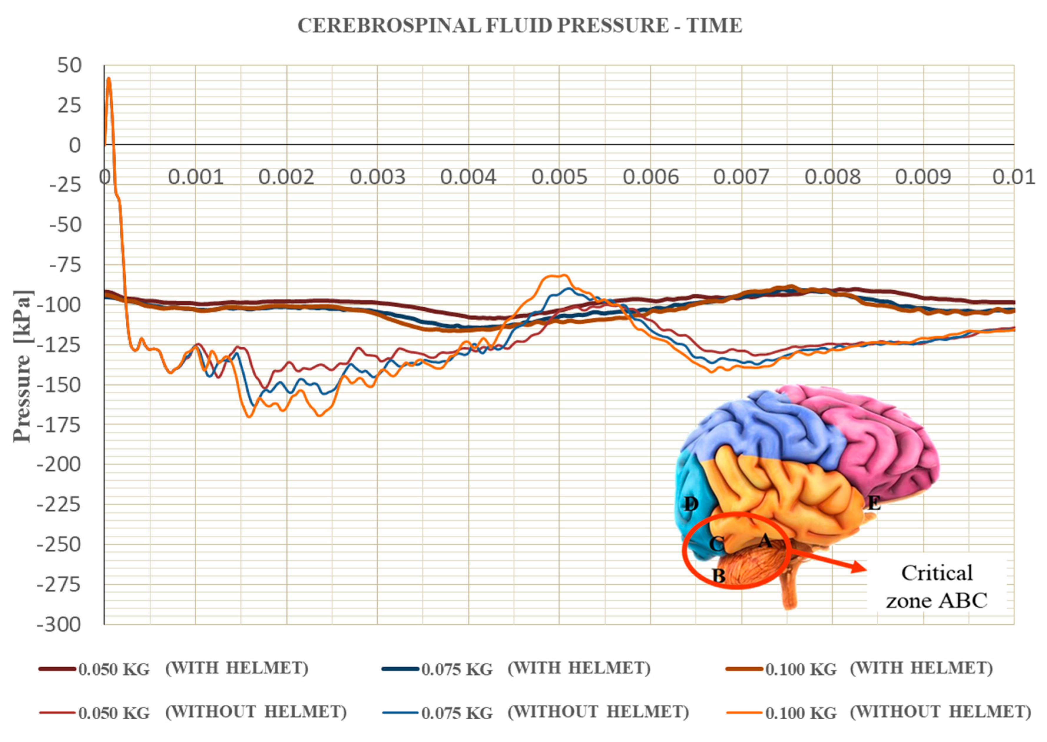
The pressure in cerebrospinal fluid shows that the area with a higher probability of suffering a subdural hematoma injury is located between the cerebellum and the lower temporal and occipital lobes (in Figure 13, this area is bounded by letters A, B, and C) and the middle occipital lone (location D). Although there is also a risk of injury in zone E, the probability of injury is reduced to 50% (pressure between −94 and −135 kPa).
Figure 13 shows the evolution of the pressure in the cerebrospinal fluid during the simulation. This pressure has been calculated as an average of the ABC areas since they are the most critical areas for damage. It has been observed that the calculated average value is slightly lower than point pressure peaks in each of the zones. This assumption is acceptable since, for the evaluation of the criterion, it is a more conservative position.
In addition, the pressure value is reduced and does not reach −94 kPa in D and E areas, so no injury is observed wearing helmet in these brain locations.
Figure 13, and more detailed in Table 9, show a reduction in the peaks pressure of these critical areas due to the presence of the helmet: 28.40% for the 0.050 kg load, 29.95% for the 0.075 kg of TNT, and finally a reduction 31.56% for the maximum explosive load studied, 0.100 kg. A reduction of around 30% of the pressure in these areas is observed due to the action of the protective helmet for the cases studied.

3.5. Cerebellum Strain

The last criterion used in this work to evaluate user brain damage is the cerebellum strains due to the action of blast loads. This criterion was formulated by Zhang et al. [56] in which cerebellum strain levels are related to the likelihood of medium Traumatic Brain Injuries (mTBI) as follows:
-
If cerebellum strain is higher than 0.14 (conservative criteria), a 25% probability of mTBI exists.
-
If the strains increase up to 0.19 (optimum criteria), the mTBI probability increases to 50%.
-
Finally, a mTBI probability of 80% is assumed if strains are higher than 0.24 (broad criteria).
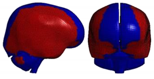
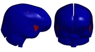
In order to carry out this analysis, strains have been measured in the same set studied by Zhang et al. [9], which is made up of the parts corresponding to the grey and white matter, as well as the upper part of the brain stem that suffers strains of lesser magnitude. The maximum principal strain values and the instant of time when it occurs have been obtained. Table 10 shows these values for the different cases studied. The zones where maximum strains appear are rounded in black in all frames.
By observing the results obtained, the reduction in maximum principal strain is quite remarkable at around 60%; however, it is not enough to prevent an mTBI from occurring since using the protection does not reduce strains below 0.24, exposing the subject to an 80% probability of having an mTBI.
The analysis carried out focuses on classifying the maximum principal strain according to the criteria presented. However, the percentage of brain volume that exceeds the maximum strain value of 0.24 is analyzed below. The brain volume of the study is 1201.04 cm3. Table 11 shows the brain volumes affected by 0.24 strains for all the cases.
In all cases, as previously mentioned, the value of 0.24 deformation is reached, however, the volume of the brain is reduced by 95% for the three load cases when the protective helmet is used, limiting the risk area to the superficial part of the brain, preventing the corpus callosum, cerebellum and brain stem from being in a damaged area.

4. Conclusions

This paper analyses the injuries produced in the brain and the level of protection offered by the EOD helmet exposed to different quantities of an explosive charge, by developing numerical simulations of the head exposed to the explosions while wearing and not wearing a helmet.
The use of the helmet delays the impact of the shockwave on the wearer’s head. The helmet absorbs part of its energy both through the effect of the aramid fiber visor and shell and through the compression of the internal foams. In all the cases studied, wearing an EOD helmet reduces the maximum values in the measured damage parameters: 80% in CG acceleration, 95% in HIC and GSI, 70% in ICP, 60% in cerebellum strains.
It is concluded that the helmet reduces the level of severity of injuries on the user: from a highly probable death due to the non-use of protective equipment to a low probability of injury, of a mild and localized nature. The EOD shell has good effectiveness for TNT front loads of up to 100 g at a distance of 681 mm. Beyond this amount, the EOD helmet may not be effective.
This study is one of the first to analyze and develop a numerical tool for this type of helmet using a human head model for considering the biomechanical response and possible damage. Therefore, it provides further insight on the future investigations with the EOD helmet for a bomb-disposal officer by analyzing possible brain damage.

Author Contributions

Conceptualization, J.A.L., J.A.-M., and M.R.-M.; methodology, B.V.M., M.R.-M., and I.R.; simulations, B.V.-M. and J.A.-M.; investigation, J.A.-M., B.V.-M., and M.R.-M.; writing—review and editing, J.A.-M., J.A.L, A.C., B.V.M., I.R., and M.R.-M.; supervision, J.A.L., M.R.-M., A.C., and J.A.-M.; funding acquisition, M.R.-M. All authors have read and agreed to the published version of the manuscript.

Funding

This work has been carried out within the framework of the research project DPI2017-88166-R of FEDER program financed by the Ministerio de Economía, Industria y Competitividad and the Spanish Ministry of Education, Culture and Sports for the professor’s mobility program José Castillejo’s 2018 grant (CAS18/00292).

Acknowledgments

The authors acknowledge the Ministry of Economy and Competitiveness of Spain and FEDER program under the Project DPI2017-88166-R for the financial support of the work, and Marcos Rodríguez-Millán thanks the Spanish Ministry of Education, Culture and Sports for the professor’s mobility program José Castillejo’s 2018 grant (CAS18/00292).

Conflicts of Interest

The authors declare no conflict of interest.

References

  1. Townsend, M.T.; Alay, E.; Skotak, M.; Chandra, N. Effect of Tissue Material Properties in Blast Loading: Coupled Experimentation and Finite Element Simulation. Ann. Biomed. Eng. 2019, 47, 2019–2032. [Google Scholar] [CrossRef] [PubMed]
  2. NATO Standarization Agency. STANAG 2920 PPS—Ballistic Test Method for Personal Armour Materials and Combat Clothing, 2nd ed.; NATO: Brussels, Belgium, 2003. [Google Scholar]
  3. NIJ. NIJ Standard—0106.01; NIJ: Washington, DC, USA, 1981.
  4. Moore, D.F.; Jérusalem, A.; Nyein, M.; Noels, L.; Jaffee, M.S.; Radovitzky, R.A. Computational biology—Modeling of primary blast effects on the central nervous system. Neuroimage 2009, 47. [Google Scholar] [CrossRef] [PubMed]
  5. Grujicic, M.; Glomski, P.S.; He, T.; Arakere, G.; Bell, W.C.; Cheeseman, B.A. Material modeling and ballistic-resistance analysis of armor-grade composites reinforced with high-performance fibers. J. Mater. Eng. Perform. 2009, 18, 1169–1182. [Google Scholar] [CrossRef] [Green Version]
  6. Grujicic, M.; Arakere, A.; Pandurangan, B.; Grujicic, A.; Littlestone, A.; Barsoum, R. Computational investigation of shock-mitigation efficacy of polyurea when used in a combat helmet: A core sample analysis. Multidiscip. Model. Mater. Struct. 2012, 8, 297–331. [Google Scholar] [CrossRef]
  7. Panzer, M.B.; Bass, C.R.; Rafaels, K.A.; Shridharani, J.; Capehart, B.P. Primary blast survival and injury risk assessment for repeated blast exposures. J. Trauma Acute Care Surg. 2012, 72, 454–466. [Google Scholar] [CrossRef]
  8. Bass, C.R.; Panzer, M.B.; Rafaels, K.A.; Wood, G.; Shridharani, J.; Capehart, B. Brain injuries from blast. Ann. Biomed. Eng. 2012, 40, 185–202. [Google Scholar] [CrossRef]
  9. Zhang, L.; Makwana, R.; Sharma, S. Brain response to primary blast wave using validated finite element models of human head and advanced combat helmet. Front. Neurol. 2013, 4. [Google Scholar] [CrossRef] [Green Version]
  10. Rodríguez-Millán, M.; Tan, L.B.; Tse, K.M.; Lee, H.P.; Miguélez, M.H. Effect of full helmet systems on human head responses under blast loading. Mater. Des. 2017. [Google Scholar] [CrossRef] [Green Version]
  11. Sarvghad-Moghaddam, H.; Rezaei, A.; Ziejewski, M.; Karami, G. Evaluation of brain tissue responses because of the underwash overpressure of helmet and faceshield under blast loading. Int. J. Numer. Method. Biomed. Eng. 2017, 33. [Google Scholar] [CrossRef]
  12. Sarvghad-Moghaddam, H.; Jazi, M.S.; Rezaei, A.; Karami, G.; Ziejewski, M. Examination of the protective roles of helmet/faceshield and directionality for human head under blast waves. Comput. Methods Biomech. Biomed. Eng. 2015, 18, 1846–1855. [Google Scholar] [CrossRef]
  13. Singh, D.; Cronin, D.S. Efficacy of visor and helmet for blast protection assessed using a computational head model. Shock Waves 2017, 27, 905–918. [Google Scholar] [CrossRef]
  14. Li, J.; Ma, T.; Huang, C.; Huang, X.; Kang, Y.; Long, Z.; Liu, M. Protective Mechanism of Helmet Under Far-field Shock Wave. Int. J. Impact Eng. 2020, 143, 103617. [Google Scholar] [CrossRef]
  15. Tan, L.B.; Tse, K.M.; Tan, Y.H.; Sapingi, M.A.B.; Tan, V.B.C.; Lee, H.P. Face shield design against blast-induced head injuries. Int. J. Numer. Method. Biomed. Eng. 2017, 33. [Google Scholar] [CrossRef] [PubMed]
  16. Tse, K.M.; Bin Tan, L.; Ali Bin Sapingi, M.; Franklyn, M.; Lee, P.V.S.; Beng Chye Tan, V.; Pueh Lee, H. The role of a composite polycarbonate-aerogel face shield in protecting the human brain from blast-induced injury: A fluid–structure interaction (FSI) study. J. Sandw. Struct. Mater. 2019, 21, 2484–2511. [Google Scholar] [CrossRef]
  17. Bass, C.D.; Davis, M.; Rafaels, K.; Rountree, M.S.; Harris, R.M.; Sanderson, E.; Andrefsky, W.; Dimarco, G.; Zielinski, M. A Methodology for Assessing Blast Protection in Explosive Ordnance Disposal Bomb Suits. Int. J. Occup. Saf. Ergon. 2005, 11, 347–361. [Google Scholar] [CrossRef] [Green Version]
  18. Dionne, J.P.; Levine, J.; Makris, A. Acceleration-based methodology to assess the blast mitigation performance of explosive ordnance disposal helmets. Shock Waves 2018, 28, 5–18. [Google Scholar] [CrossRef]
  19. Sepulveda-Lopez, D.; Antona-Makoshi, J.; Rubio, I.; Rodríguez-Millán, M. Numerical Analysis of Bicycle Helmet under Blunt Behavior. Appl. Sci. 2020, 10, 3692. [Google Scholar] [CrossRef]
  20. Antona-Makoshi, J. Traumatic Brain Injuries: Animal Experiments and Numerical Simulations to Support the Development of a Brain Injury Criterion; Chalmers University of Technology: Gothenburg, Sweden, 2016; ISBN 978-91-628-9848-9. [Google Scholar]
  21. Van Hoof, J.; Cronin, D.S.; Worswick, M.J.; Williams, K.V.; Nandlall, D. Numerical Head and Composite Helmet Models to Predict Blunt Trauma. In Proceedings of the 19th International Symposium on Ballistics, Interlaken, Switzerland, 7–11 May 2001; pp. 7–11. [Google Scholar]
  22. Tan, L.B.; Tse, K.M.; Lee, H.P.; Tan, V.B.C.; Lim, S.P. Performance of an advanced combat helmet with different interior cushioning systems in ballistic impact: Experiments and finite element simulations. Int. J. Impact Eng. 2012, 50, 99–112. [Google Scholar] [CrossRef]
  23. Gower, H.L.; Cronin, D.S.; Plumtree, A. Ballistic impact response of laminated composite panels. Int. J. Impact Eng. 2008, 35, 1000–1008. [Google Scholar] [CrossRef]
  24. Shah, Q.H. Impact resistance of a rectangular polycarbonate armor plate subjected to single and multiple impacts. Int. J. Impact Eng. 2009, 36, 1128–1135. [Google Scholar] [CrossRef]
  25. Mark, J.E. Rubber elasticity. J. Chem. Educ. 1981, 58, 898. [Google Scholar] [CrossRef] [Green Version]
  26. Li, Y.Q.; Li, X.G.; Gao, X.L. Modeling of advanced combat helmet under ballistic impact. J. Appl. Mech. Trans. ASME 2015, 82. [Google Scholar] [CrossRef]
  27. Li, X.G.; Gao, X.L.; Kleiven, S. Behind helmet blunt trauma induced by ballistic impact: A computational model. Int. J. Impact Eng. 2016, 91, 56–67. [Google Scholar] [CrossRef]
  28. Rodríguez-Millán, M.; Ito, T.; Loya, J.A.; Olmedo, A.; Miguélez, M.H. Development of numerical model for ballistic resistance evaluation of combat helmet and experimental validation. Mater. Des. 2016, 110, 391–403. [Google Scholar] [CrossRef] [Green Version]
  29. Rubio, I.; Díaz-álvarez, A.; Bernier, R.; Rusinek, A.; Loya, J.A.; Miguelez, M.H.; Rodríguez-Millán, M. Postmortem analysis using different sensors and technologies on aramid composites samples after ballistic impact. Sensors 2020, 20, 2853. [Google Scholar] [CrossRef] [PubMed]
  30. Tham, C.Y.; Tan, V.B.C.; Lee, H.P. Ballistic impact of a KEVLAR® helmet: Experiment and simulations. Int. J. Impact Eng. 2008, 35, 304–318. [Google Scholar] [CrossRef]
  31. Rubio, I.; Rodríguez-Millán, M.; Marco, M.; Olmedo, A.; Loya, J.A. Ballistic performance of aramid composite combat helmet for protection against small projectiles. Compos. Struct. 2019, 226, 111153. [Google Scholar] [CrossRef]
  32. Palomar, M.; Belda, R.; Giner, E. Effect of different helmet shell configurations on the protection against head trauma. J. Strain Anal. Eng. Des. 2019, 54, 408–415. [Google Scholar] [CrossRef]
  33. Chang, F.-K.; Chang, K.-Y. A Progressive Damage Model for Laminated Composites Containing Stress Concentrations. J. Compos. Mater. 1987, 21, 834–855. [Google Scholar] [CrossRef]
  34. Chang, F.-K.; Chang, K.-Y. Post-Failure Analysis of Bolted Composite Joints in Tension or Shear-Out Mode Failure. J. Compos. Mater. 1987, 21, 809–833. [Google Scholar] [CrossRef]
  35. Moss, W.C.; King, M.J.; Blackman, E.G. Skull flexure from blast waves: A mechanism for brain injury with implications for helmet design. Phys. Rev. Lett. 2009, 103. [Google Scholar] [CrossRef] [PubMed] [Green Version]
  36. McElhaney, J.H. Handbook of Human Tolerance; Japan Automobile Research Institute: Ibaraki, Japan, 1976. [Google Scholar]
  37. Melvin, J.W.; Yoganandan, N. Biomechanics of Brain Injury: A Historical Perspective; Springer: New York, NY, USA, 2015; ISBN 978-14-939-1732-7. [Google Scholar]
  38. Jin, X.; Yang, K.H.; King, A.I. Mechanical properties of bovine pia-arachnoid complex in shear. J. Biomech. 2011, 44, 467–474. [Google Scholar] [CrossRef] [PubMed]
  39. Arbogast, K.B.; Margulies, S.S. Material characterization of the brainstem from oscillatory shear tests. J. Biomech. 1998, 31, 801–807. [Google Scholar] [CrossRef]
  40. Brolin, K.; Halldin, P. Development of a Finite Element Model of the Upper Cervical Spine and a Parameter Study of Ligament Characteristics. Spine 2004, 29, 376–385. [Google Scholar] [CrossRef]
  41. Yoganandan, N.; Kumaresan, S.; Pintar, F.A. Geometric and Mechanical Properties of Human Cervical Spine Ligaments. J. Biomech. Eng. 2000, 122, 623–629. [Google Scholar] [CrossRef]
  42. Tse, K.M.; Tan, L.B.; Yang, B.; Tan, V.B.C.; Lee, H.P. Effect of helmet liner systems and impact directions on severity of head injuries sustained in ballistic impacts: A finite element (FE) study. Med. Biol. Eng. Comput. 2017, 55, 641–662. [Google Scholar] [CrossRef]
  43. Nyein, M.K.; Jason, A.M.; Yu, L.; Pita, C.M.; Joannopoulos, J.D.; Moore, D.F.; Radovitzky, R.A. In silico investigation of intracranial blast mitigation with relevance to military traumatic brain injury. Proc. Natl. Acad. Sci. USA 2010, 107, 20703–20708. [Google Scholar] [CrossRef] [Green Version]
  44. Grujicic, M.; Arakere, G.; He, T. Material-modeling and structural-mechanics aspects of the traumatic brain injury problem. Multidiscip. Model. Mater. Struct. 2010, 6, 335–363. [Google Scholar] [CrossRef]
  45. Grujicic, M.; Bell, W.C.; Pandurangan, B.; Glomski, P.S. Fluid/Structure interaction computational investigation of blast-wave mitigation efficacy of the advanced combat helmet. J. Mater. Eng. Perform. 2011, 20, 877–893. [Google Scholar] [CrossRef]
  46. Grujicic, M.; Bell, W.C.; Pandurangan, B.; He, T. Blast-wave impact-mitigation capability of polyurea when used as helmet suspension-pad material. Mater. Des. 2010, 31, 4050–4065. [Google Scholar] [CrossRef]
  47. Jenson, D.; Unnikrishnan, V.U. Energy dissipation of nanocomposite based helmets for blast-induced traumatic brain injury mitigation. Compos. Struct. 2015, 121, 211–216. [Google Scholar] [CrossRef]
  48. Mott, D.R.; Young, T.R.; Schwer, D.A. Blast Loading on the Head Under a Military Helmet: Effect of Face Shield and Mandible Protection. In Proceedings of the 52nd Aerospace Sciences Meeting, National Harbor, MD, USA, 13–17 January 2014. [Google Scholar]
  49. NIJ. Public Safety Bomb Suit Standard NIJ Standard-0117.00; NIJ: Washington, DC, USA, 2016.
  50. Ganpule, S.; Gu, L.; Alai, A.; Chandra, N. Role of helmet in the mechanics of shock wave propagation under blast loading conditions. Comput. Methods Biomech. Biomed. Engin. 2012, 15, 1233–1244. [Google Scholar] [CrossRef] [PubMed] [Green Version]
  51. Gadd, C.W. Impact Acceleration Stress; National Academies Press: Washington, DC, USA, 1962; ISBN 978-0-309-34021-2. [Google Scholar]
  52. Hayes, W.C.; Erickson, M.S.; Power, E.D. Forensic Injury Biomechanics. Annu. Rev. Biomed. Eng. 2007, 9, 55–86. [Google Scholar] [CrossRef] [PubMed]
  53. Gennarelli, T.A.; Wodzin, E. AIS 2005: A contemporary injury scale. Injury 2006, 37, 1083–1091. [Google Scholar] [CrossRef]
  54. Ward, C.; Chan, M.; Nahum, A. Intracranial Pressure—A Brain Injury Criterion. SAE Trans. 1980, 89, 3867–3880. [Google Scholar]
  55. Deck, C.; Willinger, R. Improved head injury criteria based on head FE model. Int. J. Crashworthiness 2008, 13, 667–678. [Google Scholar] [CrossRef]
  56. Zhang, L.; Yang, K.H.; King, A.I. A Proposed Injury Threshold for Mild Traumatic Brain Injury. J. Biomech. Eng. 2004, 126, 226–236. [Google Scholar] [CrossRef]
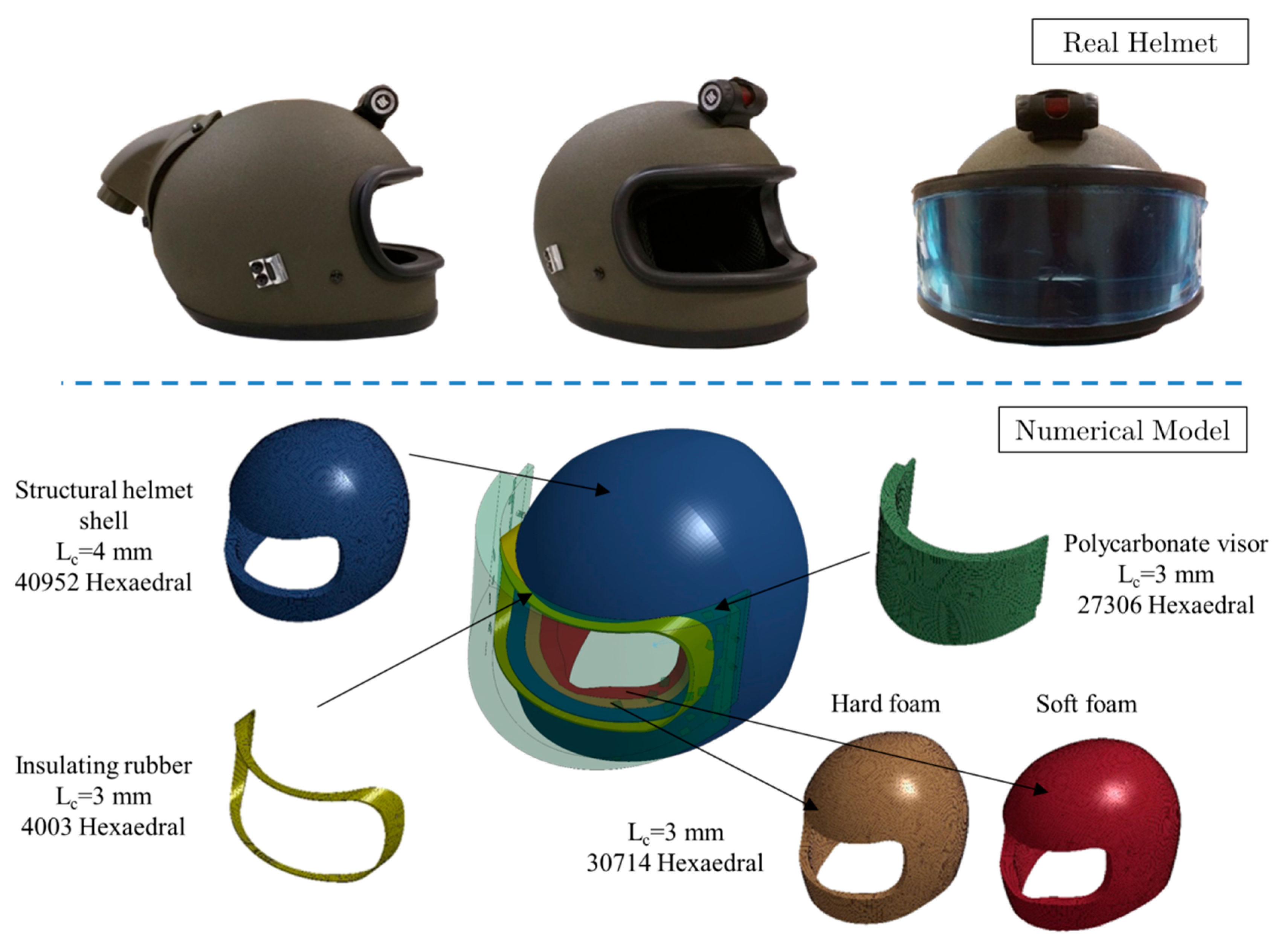
Figure 1. Explosive ordinance disposal (EOD) helmet model description.
Applsci 10 08227 g001
Figure 2. Stress–strain curves for both inner foams.
Applsci 10 08227 g002
Figure 3. Human head model used in this work. (a) Complete head–neck model with the brain and spinal detail. (b) and (c) Brain parts.
Applsci 10 08227 g003
Figure 4. Head–helmet assembly and explosive load position.
Applsci 10 08227 g004
Figure 5. Head–helmet assembly drop weight simulation. (a) Isometric view; (b) Section view.
Applsci 10 08227 g005
Figure 6. Drop weight model simulation evolution.
Applsci 10 08227 g006aApplsci 10 08227 g006b
Figure 7. Blast simulation for 0.100 kg TNT: comparison with and without helmet use.
Applsci 10 08227 g007aApplsci 10 08227 g007b
Figure 8. Center of gravity brain position to calculate the acceleration.
Applsci 10 08227 g008
Figure 9. Resultant acceleration evolution measured on the center of gravity of the brain. (a) Without helmet model. (b) Model using the protective helmet.
Applsci 10 08227 g009
Figure 10. Probability of injury curves for different values of HIC parameter.
Applsci 10 08227 g010
Figure 11. HIC parameter evolution with the explosive load.
Applsci 10 08227 g011
Figure 12. Intracranial pressure evolution with and without helmet for the blast loads of 0.050, 0.075, and 0.100 kg.
Applsci 10 08227 g012
Figure 13. Cerebrospinal fluid pressure evolution comparison for all cases studied.
Applsci 10 08227 g013
Table 1. Mechanical properties of different parts of the EOD helmet.
PartsMaterial Model
LS-Dyna
Nº ElementsElement TypeSizeMaterial PropertiesSource
Helmet Shell*MAT_COMPOSITE_DAMAGE40,952Hexaedric solid
-
4 mm longitudinal /thickness
Table 2Van Hoof, J et al.
Tan et al.
Gower et al.
[21,22,23]
Visor*MAT_PLASTIC_KINEMATIC27,036Hexaedric solid
-
4.5 mm longitudinal
-
3 mm thickness
E = 1.5 GPa
υ = 0.37
Shah [24]
Insulating rubber*MAT_ELASTIC4003Hexaedric solid
-
3 mm longitudinal 1 mm thickness
E = 5 GPa
υ = 0.4
Mark [25]
Hard foam*MAT_LOW_DENSITY_FOAM30,714Hexaedric solid
-
4 mm longitudinal /thickness
Stress–strain curvesZhang et al.
Li et al.
[9,26,27]
Soft foam*MAT_LOW_DENSITY_FOAM30,714Hexaedric solid
-
3 mm longitudinal 5 mm thickness
Stress–strain curves[9,26,27]
Table 2. Mechanical properties of aramid composite used for helmet shell.
ρ (kg/m3)Density1230
E 1 [GPa]Young’s Modulus direction 1118.5
E 2 [GPa]Young’s Modulus direction 2218.5
E 3 [GPa]Young’s Modulus direction 336
ν12 [–]Poisson’s ratio plane 120.25
ν13 [–]Poisson’s ratio plane 130.33
ν23 [–]Poisson’s ratio plane 230.33
G 12 [GPa]Shear Modulus plane 120.77
G 13 [GPa]Shear Modulus plane 132.5
G 23 [GPa]Shear Modulus plane 232.5
X t [GPa]Tensile strength direction 110.555
Y t [GPa]Tensile strength direction 220.555
S c [GPa]Shear Strength plane 120.588
Y c [GPa]Compressive strength direction 221.086
S n [GPa]Normal tensile strength0.835
S 13 [GPa]Transverse shear strength1.06
S 23 [GPa]Transverse shear strength1.06
Table 3. Mechanical properties of different parts of the human head.
Head PartMaterial Model
LS-Dyna
Material PropertiesSource
Scalp and Neck FleshFu Chang FoamStress–Strain curves at 3 Strain ratesHuman cadaver Scalp in Compression, McElhaney [36]
Skull TablesPiece-Wise Linear PlasticityE = 6.48 GPaHuman Skull Tables in Shear, McElhaney [36]
Skull DiploeIsotropic Elastic PlasticE = 40 MPaMcElhaney [36]
Dura MaterElasticE = 40 MPaHuman Dura in Tension Melvin [37]
Pia MaterElasticE = 12.5 MPaBovine Pia-Arachnoid in Shear [38]
Cerebrospinal Fluid (CSF)Elastic FluidK = 2.1 GPa
υ = 0.4999
McElhaney [36]
BrainBrain Linear
Viscoelastic
G0 = 1.6 kPa
G1 = 0.9 kPa
Porcine Brain Tissue in Shear Arbogast & Margulies [39]
Falx and TentoriumElasticE = 12.5 MPaJin et al. [38]
VertebraeRigid--
Intervertebral Discs
and Facet Joints
ElasticE = 10 MPaBrolin et al. [40]
Neck LigamentsElasticE = 43.8 MPaYoganandan [41]
Table 4. Literature review about different works about blast load effect on the protective helmet.
AuthorsLoad [kg TNT]Target Distance [m]Comments
Zhang et al. [9]0.85 kg de TNT
1.50 kg de TNT
1.70 kg de TNT
5.40 kg de TNT
1.06 m
1.45 m
1.85 m
2.80 m
Based on Bowen’s lung damage threshold curves
Rodríguez-Millán et al. [10]0.100 kg de TNT0.40 mConfigurations (with head): Helmet//Helmet + Mandible//Helmet + Visor//Helmet + Visor + Mandible
Nyeina et al. [43]3.160 gr de TNT0.12 mConfigurations: Head (only)//Head+Helmet//Head + Helmet + Visor
Grujicic et al. [44,45,46]0.0698 kg de TNT
0.3240 kg de TNT
0.60 m
0.60 m
- overpressure of 5.2 atm ➔ Blast load lung injury threshold
- overpressure of 18.6 atm ➔ 50% chance of death from lung injury
Jenson et al. [47]0.038 kg de TNT
0.093 kg de TNT
0.227 kg de TNT
0.80 m
0.80 m
0.80 m
-
Mott et al. [48]1.500 kg de C-4 (2.010 kg de TNT aprox.)3.00 mConfigurations (with head): Helmet//Helmet + Mandible//Helmet + Visor//Helmet + Visor + Mandible
Table 5. Maximum acceleration and time for all cases studied.
CaseTNT [kg]Maximum Acceleration [m/s2–g]Time amáx [ms]
Without Helmet0.0503916.9–399.31.45
0.0755267–536.921.37
0.1006430.1–655.51.29
With Helmet0.050771.6–78.73.92
0.0751109.3–113.13.68
0.1001456.9–148.53.43
Table 6. Gadd Severity Index (GSI) parameter Head Injury Criteria (HIC) values obtained using both methods presented.
CaseTNT [kg]HICGSI
Without Helmet0.0501235.01537.5
0.0752968.03620.2
0.1005552.06675.5
With Helmet0.05061.975.9
0.075170.3199.2
0.100352.7403.3
Table 7. Probability of brain injury at different AIS (Abbreviated Injury Scale) levels for varying blast mass, based on HIC parameter.
CaseTNT (kg)AIS ≥ 1 (%)AIS ≥ 2 (%)AIS ≥ 3 (%)AIS ≥ 4 (%)AIS ≥ 5 (%)AIS 6 (%)
Without Helmet0.05010096733270
0.07510010010010010099
0.100100100100100100100
With Helmet0.050210000
0.0751662000
0.10054206200
Table 8. Maximum intracranial pressure and time in when it occurs for both cases studied.
CaseTNT [kg]Intracranial Pressure Peak [kPa]Time [ms]
Without Helmet0.050282.81.74
0.075418.61.66
0.100540.61.54
With Helmet0.05080.24.40
0.075121.74.28
0.100150.24.04
Table 9. Maximum cerebrospinal fluid pressure for both cases studied, with/without helmet.
Case TNT [kg]Cerebrospinal Fluid Press [kPa]Time [ms]
Without Helmet0.050−151.731.78
0.075−163.301.66
0.100−170.031.58
With Helmet0.050−108.644.28
0.075−114.394.12
0.100−116.373.88
Table 10. Maximum principal strain and its localization on the brain.
0.050 kg TNT0.075 kg TNT0.100 kg TNT
Without Helmet Applsci 10 08227 i001 Applsci 10 08227 i002 Applsci 10 08227 i003
ε prin max = 0.85 t = 2.02 ms ε prin max = 1.06 t = 2.14 ms ε prin max = 1.18 t = 2.14 ms
With Helmet Applsci 10 08227 i004 Applsci 10 08227 i005 Applsci 10 08227 i006
ε prin max = 0.29 T = 4.65 ms ε prin max = 0.40 T = 4.44 ms ε prin max = 0.54 T = 4.12 ms
Table 11. Brain volume affected by 0.24 strain for all studied cases.
CasesWithout HelmetWith Helmet
0.050 kg TNT Applsci 10 08227 i007 Applsci 10 08227 i008
%Vol = 6.52%Vol = 0.01
0.075 kg TNT Applsci 10 08227 i009 Applsci 10 08227 i010
%Vol = 15.29%Vol = 0.11
0.100 kg TNT Applsci 10 08227 i011 Applsci 10 08227 i012
%Vol = 23.12%Vol = 1.07
Publisher’s Note: MDPI stays neutral with regard to jurisdictional claims in published maps and institutional affiliations.